WO2020217331A1 - Système de fabrication et procédé de fabrication d'un compact fritté - Google Patents
Système de fabrication et procédé de fabrication d'un compact fritté Download PDFInfo
- Publication number
- WO2020217331A1 WO2020217331A1 PCT/JP2019/017351 JP2019017351W WO2020217331A1 WO 2020217331 A1 WO2020217331 A1 WO 2020217331A1 JP 2019017351 W JP2019017351 W JP 2019017351W WO 2020217331 A1 WO2020217331 A1 WO 2020217331A1
- Authority
- WO
- WIPO (PCT)
- Prior art keywords
- sintered body
- powder
- robot
- sintering
- manufacturing system
- Prior art date
- Legal status (The legal status is an assumption and is not a legal conclusion. Google has not performed a legal analysis and makes no representation as to the accuracy of the status listed.)
- Ceased
Links
Images





Classifications
-
- B—PERFORMING OPERATIONS; TRANSPORTING
- B22—CASTING; POWDER METALLURGY
- B22F—WORKING METALLIC POWDER; MANUFACTURE OF ARTICLES FROM METALLIC POWDER; MAKING METALLIC POWDER; APPARATUS OR DEVICES SPECIALLY ADAPTED FOR METALLIC POWDER
- B22F3/00—Manufacture of workpieces or articles from metallic powder characterised by the manner of compacting or sintering; Apparatus specially adapted therefor ; Presses and furnaces
- B22F3/12—Both compacting and sintering
- B22F3/16—Both compacting and sintering in successive or repeated steps
- B22F3/162—Machining, working after consolidation
-
- B—PERFORMING OPERATIONS; TRANSPORTING
- B22—CASTING; POWDER METALLURGY
- B22F—WORKING METALLIC POWDER; MANUFACTURE OF ARTICLES FROM METALLIC POWDER; MAKING METALLIC POWDER; APPARATUS OR DEVICES SPECIALLY ADAPTED FOR METALLIC POWDER
- B22F3/00—Manufacture of workpieces or articles from metallic powder characterised by the manner of compacting or sintering; Apparatus specially adapted therefor ; Presses and furnaces
-
- B—PERFORMING OPERATIONS; TRANSPORTING
- B22—CASTING; POWDER METALLURGY
- B22F—WORKING METALLIC POWDER; MANUFACTURE OF ARTICLES FROM METALLIC POWDER; MAKING METALLIC POWDER; APPARATUS OR DEVICES SPECIALLY ADAPTED FOR METALLIC POWDER
- B22F3/00—Manufacture of workpieces or articles from metallic powder characterised by the manner of compacting or sintering; Apparatus specially adapted therefor ; Presses and furnaces
- B22F3/003—Apparatus, e.g. furnaces
-
- B—PERFORMING OPERATIONS; TRANSPORTING
- B22—CASTING; POWDER METALLURGY
- B22F—WORKING METALLIC POWDER; MANUFACTURE OF ARTICLES FROM METALLIC POWDER; MAKING METALLIC POWDER; APPARATUS OR DEVICES SPECIALLY ADAPTED FOR METALLIC POWDER
- B22F3/00—Manufacture of workpieces or articles from metallic powder characterised by the manner of compacting or sintering; Apparatus specially adapted therefor ; Presses and furnaces
- B22F3/005—Loading or unloading powder metal objects
-
- B—PERFORMING OPERATIONS; TRANSPORTING
- B22—CASTING; POWDER METALLURGY
- B22F—WORKING METALLIC POWDER; MANUFACTURE OF ARTICLES FROM METALLIC POWDER; MAKING METALLIC POWDER; APPARATUS OR DEVICES SPECIALLY ADAPTED FOR METALLIC POWDER
- B22F3/00—Manufacture of workpieces or articles from metallic powder characterised by the manner of compacting or sintering; Apparatus specially adapted therefor ; Presses and furnaces
- B22F3/24—After-treatment of workpieces or articles
- B22F2003/247—Removing material: carving, cleaning, grinding, hobbing, honing, lapping, polishing, milling, shaving, skiving, turning the surface
-
- B—PERFORMING OPERATIONS; TRANSPORTING
- B22—CASTING; POWDER METALLURGY
- B22F—WORKING METALLIC POWDER; MANUFACTURE OF ARTICLES FROM METALLIC POWDER; MAKING METALLIC POWDER; APPARATUS OR DEVICES SPECIALLY ADAPTED FOR METALLIC POWDER
- B22F2301/00—Metallic composition of the powder or its coating
- B22F2301/35—Iron
-
- B—PERFORMING OPERATIONS; TRANSPORTING
- B22—CASTING; POWDER METALLURGY
- B22F—WORKING METALLIC POWDER; MANUFACTURE OF ARTICLES FROM METALLIC POWDER; MAKING METALLIC POWDER; APPARATUS OR DEVICES SPECIALLY ADAPTED FOR METALLIC POWDER
- B22F2998/00—Supplementary information concerning processes or compositions relating to powder metallurgy
- B22F2998/10—Processes characterised by the sequence of their steps
Definitions
- the present invention relates to a sintered body manufacturing system and manufacturing method.
- Patent Documents 1 and 2 describe a preparatory step for preparing a raw material powder containing a metal powder, a molding step for producing a powder compact by uniaxially pressing the raw material powder using a mold, and a powder compact.
- a method for manufacturing a sintered body including a processing step of manufacturing a processed molded body by machining the above and a sintering step of sintering the processed molded body to obtain a sintered body is described.
- Patent Document 2 it is recommended that the average relative density of the entire compact compact is 93% or more in the above molding step.
- the production system includes a molding apparatus for producing a powder compact having a relative density of 93% or more in whole or a part by uniaxially pressing a raw material powder containing a metal powder, and the powder.
- a robot processing device having an articulated robot that produces a processed molded body by machining the molded body, and induced heating sintering that produces a sintered body by sintering the processed molded body by high-frequency induction heating. It is equipped with a furnace.
- the manufacturing system comprises a processing apparatus for producing a processed molded product by machining a powder compact according to 3D data of an object product as a reference for the shape, and the processed molded product.
- a sintering device for producing a sintered body by sintering is provided.
- the sintered body manufacturer will manufacture and manufacture the sintered body that follows the customer's current product as soon as possible. It is preferable to present the united product as a sample to the customer.
- Patent Documents 1 and 2 the delivery date of the sintered body presented to the customer as a sample is not assumed.
- An object of the present disclosure is to make it possible to shorten the delivery time of a sintered body in view of such conventional problems. Further, it is desired that the equipment for manufacturing the sintered body presented to the customer as a sample is compact (miniaturized). An object of the present disclosure is to make it possible to make a sintered body manufacturing facility compact in view of such conventional problems.
- the delivery time of the sintered body can be shortened.
- the manufacturing equipment for the sintered body can be made compact.
- the production system of the present embodiment includes a molding apparatus for producing a powder compact having a relative density of 93% or more in whole or a part by uniaxially pressing a raw material powder containing a metal powder, and the powder.
- a robot processing device having an articulated robot that produces a processed molded body by machining the molded body, and induced heating sintering that produces a sintered body by sintering the processed molded body by high-frequency induction heating. It is equipped with a furnace.
- the induction heating sintering furnace capable of producing the sintered body in a shorter time as compared with the belt type continuous sintering furnace is provided, the delivery time of the sintered body can be shortened.
- a robot processing apparatus having a smaller installation space than a 5-axis machining center and an induction heating sintering furnace having a smaller installation space than a belt-type continuous sintering furnace are provided. Manufacturing equipment can be made compact.
- the manufacturing system of the present embodiment it is preferable to further include an acquisition unit for acquiring 3D data of the target product as a reference for the shape.
- the acquisition unit acquires the 3D data of the target product as the reference of the shape. Therefore, as described later, the inspection of the sintered body and the creation of the processing program based on the acquired 3D data are performed. Will be able to execute.
- the manufacturing system of the present embodiment is further provided with an inspection device that executes at least one inspection of the dimensional accuracy of the sintered body and the presence or absence of defects based on the 3D data of the target product. preferable. According to the manufacturing system of the present embodiment, since the inspection device performs the above inspection, it is possible to manufacture a high-precision sintered body that is comparable to the target product.
- a computer device for creating a machining program for controlling the operation of the robot machining device based on the 3D data of the target product is further provided, and the robot machining device is provided. It is preferable to prepare the processed molded product based on the processing program.
- the computer device creates the above-mentioned machining program, and the robot machining device prepares the machined molded product based on the above-mentioned machining program, so that the shape is substantially the same as that of the target product.
- the robot processing apparatus can be controlled so as to process the powder compact.
- the robot processing apparatus has a plurality of the articulated robots, and the plurality of articulated robots hold a tool for processing the powder compact. It is preferable to include a robot and a second robot that holds the powder compact.
- the relative density of the powder compact is 93% or more, even if the powder compact held by the second robot is cut with the tool held by the first robot. , The powder compact does not break. Therefore, the powder compact can be processed quickly. In addition, the tool can be brought into contact with the powder compact at an arbitrary angle, and complicated machining can be performed quickly.
- a processing device for producing a processed molded product by machining a powder compact according to the 3D data of the target product as a reference for the shape, and the processed molded product are used.
- a sintering device for producing a sintered body by sintering is provided.
- the processing apparatus manufactures the processed molded product by machining the powder compact according to the 3D data of the target product, and the sintering apparatus sintered the processed molded product.
- a sintered body is produced, so that a sintered body having substantially the same shape as the target product can be produced in a short time. Therefore, the delivery time of the sintered body can be shortened.
- the manufacturing system of the present embodiment it is preferable to further include a 3D scanner that acquires 3D data of the target product in a non-contact manner. According to the manufacturing system of the present embodiment, since the 3D scanner acquires the 3D data of the target product in a non-contact manner, the 3D data of the target product can be quickly acquired even if the 3D data of the target product does not exist. ..
- the processing device is a robot processing device having an articulated robot, in order to control the operation of the robot processing device based on the 3D data of the target product. It is preferable to further provide a computer device for creating the machining program of.
- the manufacturing equipment for the sintered body can be made compact.
- the robot processing device since the computer device creates the above-mentioned processing program, the robot processing device can be controlled so as to process the powder compact into substantially the same shape as the target product. ..
- the manufacturing system of the present embodiment is further provided with an inspection device that executes at least one inspection of the dimensional accuracy of the sintered body and the presence or absence of defects based on the 3D data of the target product. preferable. According to the manufacturing system of the present embodiment, since the inspection device performs the above inspection, it is possible to manufacture a high-precision sintered body that is comparable to the target product.
- a molding apparatus for producing the powder compact having a relative density of 93% or more in whole or a part by uniaxially pressing the raw material powder containing the metal powder is further provided.
- the molding apparatus uniaxially pressurizes the raw material powder containing the metal powder to produce the powder compact having the above relative density, so that the powder compact with high precision can be quickly produced. can get. Therefore, the delivery time of the sintered body can be shortened.
- the sintering apparatus is preferably an induction heating sintering furnace that sinters the processed molded product by high frequency induction heating.
- the induction heating sintering furnace can produce the sintered body in a shorter time than the belt type continuous sintering furnace, so that the delivery time of the sintered body can be shortened. Further, since the installation space of the induction heating sintering furnace is smaller than that of the belt type continuous sintering furnace, the equipment for manufacturing the sintered body can be made compact.
- the processing device is a robot processing device having an articulated robot, and the sintering device is the processing molding. It is an induction heating sintering furnace that sinters a body by high frequency induction heating, and the device mounted on the moving device preferably includes the robot processing device and the induction heating sintering furnace.
- the mobile device since the mobile device is equipped with a robot processing device and an induction heating sintering furnace, these devices can be transported to a point near the customer's residence. Therefore, the sintered body can be manufactured at a point near the customer's residence. Therefore, the sintered body can be delivered to the customer in a shorter time than when the sintered body is manufactured in a factory far from the customer's residence.
- the device mounted on the mobile device includes a 3D scanner that acquires 3D data of the target product in a non-contact manner. According to the manufacturing system of the present embodiment, since the 3D scanner acquires the 3D data of the target product in a non-contact manner, the 3D data of the target product is obtained even if the customer or a third party does not store the 3D data of the target product. Can be obtained quickly.
- the relative density of the whole or a part of the powder compact is 96% or more.
- the strength of the sintered body is higher than that when the relative density is less than that, and the powder compact is processed by a robot processing device. This is because it becomes hard to break.
- the manufacturing method of the present embodiment is a manufacturing method of a sintered body for manufacturing the sintered body by using the manufacturing system according to any one of (1) to (14) described above. Therefore, the manufacturing method of the present embodiment has the same effect as the manufacturing system according to any one of (1) to (14) described above.
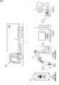
- FIG. 1 is an explanatory diagram showing an outline of a method for manufacturing the sintered body S.
- the customer provides the manufacturer with the current product C, which is a current component to be incorporated into, for example, the company's product (finished product).
- the manufacturer manufactures the sintered body S according to the current product C, and provides the manufactured sintered body S to the customer as a sample.
- the method for producing the sintered body S according to the present embodiment includes the procedures from step 1 to step 5.
- the manufacturer manufactures the sintered body S having substantially the same shape as the current product C through steps 1 to 5.
- the outline of each step 1 to 5 will be described below.
- the combination of all or part of the devices used in the manufacturing method shown in FIG. 1 is referred to as a "manufacturing system" of the sintered body S.
- Step 1 Acquisition of 3D data
- Step 1 is a step of acquiring 3D CAD (Computer Aided Design) data of the target product (customer's current product C in this embodiment) which is a reference for the shape of the sintered body S. ..
- 3D CAD Computer Aided Design
- the three-dimensional CAD data is also referred to as "3D data”.
- 3D data is acquired by reading the actual product C of the current product C with the 3D scanner 1.
- the 3D scanner becomes the 3D data acquisition unit.
- the 3D data specified by the customer, etc. is transmitted by e-mail or data is transferred using a USB memory.
- the data may be directly input to the computer device 2 in step 2.
- the 3D scanner 1 becomes unnecessary or non-use, and the computer device 2 becomes a 3D data acquisition unit.
- Step 2 is a step of creating a molded body processing program (setting manufacturing conditions)
- Step 2 is a step of creating a molded body machining program (hereinafter, also referred to as “machining program”) from the 3D data acquired in step 1.
- the machining program is a computer program for controlling the operation of the molded body machining apparatus 32 used in step 3.
- the creation of the machining program is executed by, for example, the computer device 2 that stores the CAD / CAM (Computer Aided Manufacturing) software.
- CAD / CAM Computer Aided Manufacturing
- Step 3 Manufacture of the sintered body by processing the molded body
- Step 3 is a step of manufacturing the sintered body S by the manufacturing equipment 3.
- the manufacturing equipment 3 used in step 3 includes a step P2 in which the molded body processing device (hereinafter, also referred to as “processing device”) 32 processes the powder compact M before sintering.
- the processing apparatus 32 performs a predetermined processing on the powder compact M according to the processing program created in step 2.
- Step 4 Modify the part processing program (optimize manufacturing conditions)
- Step 4 is a step of modifying the machining program based on the 3D data of the accepted product S sintered body S manufactured in step 3.
- the modification of the machining program is executed by, for example, a computer device 4 that stores CAD / CAT (Computer Aided Testing) software.
- the modification result of the machining program is fed back to the machining apparatus 32 in step 3.
- the modification result of the machining program may be fed back to the computer device 2 that creates the machining program (step 2).
- Step 5 Provision of Sintered Body (Sample Product)
- one or a plurality of sintered bodies S manufactured by the modification program of Step 4 are determined as the sample product, and the sintered body determined as the test product is used.
- This is a step of providing the body S to the customer.
- Customers who are provided with the sintered body S, which is a sample product can compare the performance of the current product C and the sintered body S, for example, by using their own test equipment. If the performance of the sintered body S provided as the sample product is equal to or higher than the performance of the current product C, the customer may replace the current product C with the sintered body S.
- the manufacturing equipment 3 (see FIG. 3) for processing the unsintered powder compact M is used in step 3, processing such as cutting is easy and the productivity is excellent. Therefore, the sintered body S can be manufactured at a lower cost and in a shorter delivery time than, for example, a cast product or a forged product. Therefore, when the current product C is a cast or forged product, the customer can expect to suppress the manufacturing cost and shorten the procurement period by replacing the current product C with the sintered body S.
- a sintered body S such as a sprocket, a rotor, a gear, a ring, a flange, a pulley, a vane, or a bearing, which is incorporated in a machine such as an automobile, can be manufactured.
- the sintered body S is not limited to products in the automobile field.
- a sintered body S such as an aircraft turbine blade, an artificial bone and an artificial joint used in the medical field, or a radiation shielding component used in the nuclear field can be manufactured. Wide range of applications.
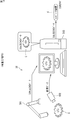
- FIG. 2 is an explanatory diagram showing an example of the apparatus used in step 1 and step 2.
- the apparatus used in step 1 comprises a non-contact three-dimensional shape measuring machine (hereinafter, referred to as “3D scanner”) 1.
- the non-contact type 3D scanner 1 is a device that detects surface irregularities (distance to an arbitrary point on the surface) without touching an object, converts the detection result into three-dimensional CAD data, and captures it in the computer device 2. is there.
- the 3D scanner 1 acquires three-dimensional coordinate data (X, Y, Z) of each point on the surface of the object while irradiating the object with light.
- the 3D scanner 1 converts the acquired point cloud data into polygon data to generate a mesh-like three-dimensional figure.
- the 3D scanner 1 converts the point cloud data constituting the three-dimensional figure into three-dimensional CAD data in a predetermined file format, and transmits the converted three-dimensional CAD data to the computer device 2 connected to the own machine.
- the non-contact type 3D scanner 1 is roughly classified into a "laser light type” and a "pattern light type".
- the laser light type scans an object while irradiating it with a laser beam, identifies the reflected light from the object with a light receiving sensor, and measures the distance to the object by trigonometry.
- the pattern light type measures the distance from the own machine to the object by scanning while irradiating the object with the pattern light and identifying the line of the striped pattern.
- the pattern light type can perform measurement faster than the laser light type. Therefore, in the example of FIG. 2, the pattern light type 3D scanner 1 is adopted.
- the 3D scanner 1 illustrated in FIG. 2 is a stationary type, but the 3D scanner 1 may be a handy type scanner that can be held and measured by the user.
- the file of the data may be read directly into the computer device 2.
- the work of scanning the actual current product C becomes unnecessary.
- the acquisition destination of the 3D CAD data of the current product C may be a third party other than the customer.
- a third party for example, a manufacturer of the current product C outsourced by a customer, or a manufacturer who disassembles the finished product and specializes in reading the 3D data of the current product C can be considered.
- the device used in step 2 comprises a computer device 2.
- the computer device 2 includes, for example, a desktop personal computer (PC).
- the type of the computer device 2 is not particularly limited.
- the type of the computer device 2 may be, for example, a notebook type or a tablet type.
- the computer device 2 is composed of an information processing device including a CPU (Central Processing Unit) and a volatile memory, and a storage device including a non-volatile memory for storing a computer program executed by the CPU and data necessary for its execution. Will be done.
- the computer device 2 also includes an input device and a display.
- the computer device 2 functions as a predetermined control device when the CPU reads the computer program into the volatile memory and executes it.
- the CAD / CAM software is installed in the computer device 2.
- the CAD / CAM software is software that realizes the creation of a machining program for operating the molded body machining device 32 in response to a user's operation input to the GUI (Graphical User Interface) of the computer device 2.
- GUI Graphic User Interface
- the CAD / CAM software for example, software such as "MasterCam” or "Robotmater” (both are registered trademarks) can be adopted. These softwares can generate a machining program according to the type of the molded body machining device 32 (for example, an articulated robot or a 5-axis machining center). Further, these softwares may be capable of generating the processing program described in JP-A-2009-226562.
- the settings required for creating the machining program include setting the shape of the workpiece (compacted compact M in this embodiment), setting the tool used for machining, setting the tool path, and the like.
- the computer device 2 creates a molded body processing program including, for example, an NC (Numerical Control) program based on the three-dimensional CAD data of the current product C and the setting information operated and input by the user.
- the computer device 2 transmits the machining program created by the CAD / CAM software to the molded body machining device 32 used in step 3.
- the molding apparatus 31 manufactures a powder compact M having a simple shape such as a cylinder or a cylinder, and the processing apparatus 32 (see FIGS. 3 and 5).
- the powder compact M is cut to produce a processed compact P having the same shape as the current product C. Therefore, the machining program created by the computer device 2 includes a program for causing the machining device 32 to perform cutting on the dust compact M having a predetermined shape.
- the three-dimensional CAD data of the powder compact M, which is the work piece, is registered in advance in the computer device 2.
- the machining program uses different tools for each type of work.
- Articulated robots 201, 202 It is preferable to include a code instructing.
- the tool used may be an end mill.
- the tool used may be a side cutter.
- the tool used When cutting so as to widen the middle of the groove formed in the powder compact M, the tool used may be a T-slot cutter.
- the tool used When cutting a through hole in the powder compact M, the tool used may be a drill.
- the drill used for drilling is a rounded tip drill having an arc-shaped cutting edge at the tip (see, for example, JP-A-2016-113657) or a candle-shaped drill (see, for example, JP-A-2016-113658). Is preferable. By adopting these drills, it is possible to suppress the occurrence of edge chipping at the hole outlet of the powder compact M.
- the preferable rotation speed of the tool used when cutting the dust compact M is, for example, 500 to 50,000 rpm. More preferably, it is 1000 to 15000 rpm.
- the preferred feed rate of the tool used when cutting the dust compact M is, for example, 20 to 6000 mm / min. More preferably, it is 200 to 2000 mm / min.
- the cutting depth and cutting position of the dust compact M are determined by the three-dimensional CAD data of the dust compact M manually input by the user in step 2 and the three-dimensional CAD data of the current product C acquired in step 1. Calculated based on.
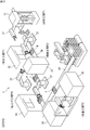
- FIG. 3 is an overall configuration diagram showing an example of the manufacturing equipment 3 used in step 3.
- the manufacturing facility 3 of the present embodiment is a facility in which devices 31 to 35 for individually executing the steps P1 to P5 are installed in order.
- the manufacturing facility 3 is installed in the factory of the manufacturer of the sintered body S.
- the manufacturing equipment 3 illustrated in FIG. 3 includes devices 31 to 35 corresponding to steps P1 to P5, a conveyor 36 passing in the vicinity of each device 31 to 35, and a work for each device 31 to 35. It comprises a production line including a robot arm 37 for carrying in and out (such as a dust compact M). The robot arm 37 executes the loading of the work from the conveyor 36 to the devices 32 to 35 and the loading and unloading of the work from the devices 31 to 35 to the conveyor 36 in units of one.
- each process P1 to P5 executed in the manufacturing facility 3 is as follows.
- P1) Molding step By uniaxially pressing the raw material powder using a mold, a powder compact M having a relative density of 93% or more in whole or part is produced.
- P2) Processing step The powder compact M is machined to produce a processed compact P.
- P4) Finishing process Finishing is performed so that the actual size of the sintered body S approaches the design size.
- P5) Inspection step Inspect the sintered body S for dimensional accuracy and / or the presence or absence of defects.
- the metal powder that is the raw material of the molding step P1 is the main material that constitutes the sintered body S.
- the metal powder include iron or iron alloy powder containing iron as a main component.
- the metal powder typically, pure iron powder or iron alloy powder is used.
- the "iron alloy containing iron as a main component” means that an iron element is contained in an amount of more than 50% by mass, preferably 80% by mass or more, and further 90% by mass or more as a constituent component.
- the iron alloy include those containing at least one alloying element selected from Cu, Ni, Sn, Cr, Mo, Mn and C.
- the above alloying elements contribute to the improvement of the mechanical properties of the iron-based sintered body.
- the total contents of Cu, Ni, Sn, Cr, Mn and Mo are 0.5% by mass or more and 5.0% by mass or less, and further 1.0% by mass or more and 3.0% by mass or less. Is mentioned.
- the content of C may be 0.2% by mass or more and 2.0% by mass or less, and further 0.4% by mass or more and 1.0% by mass or less.
- iron powder may be used as the metal powder, and the above-mentioned alloying element powder (alloyed powder) may be added thereto.
- iron is a constituent component of the metal powder at the stage of the raw material powder, but iron is alloyed by reacting with the alloying element by sintering in the sintering step P3.
- the content of the metal powder (including the alloyed powder) in the raw material powder may be, for example, 90% by mass or more, and further 95% by mass or more.
- the metal powder for example, those prepared by a water atomization method, a gas atomization method, a carbonyl method, a reduction method or the like can be used.
- the average particle size of the metal powder is, for example, 20 ⁇ m or more and 200 ⁇ m or less, and further 50 ⁇ m or more and 150 ⁇ m or less.
- the average particle size of the metal powder is easy to handle and pressure molding.
- the average particle size of the metal powder is easy to secure the fluidity of the raw material powder.
- the average particle size of the metal powder is easy to obtain a sintered body S having a dense structure.
- the average particle size of the metal powder is the average particle size of the particles that make up the metal powder.
- the average particle size of the particles is, for example, a particle size (D50) at which the cumulative volume in the volume particle size distribution measured by a laser diffraction type particle size distribution measuring device is 50%.
- Example of raw material powder 2 Induction heating
- Fe powder and Fe alloy powder may be collectively referred to as Fe-based powder.
- Fe powder, Fe alloy powder The Fe powder is pure iron powder.
- the Fe alloy powder has a plurality of Fe alloy particles containing iron as a main component and containing one or more additive elements selected from, for example, Ni and Mo. Fe alloys allow unavoidable impurities to be included. Specific examples of the Fe alloy include Fe—Ni—Mo based alloys.
- As the Fe-based powder for example, water atomizing powder, gas atomizing powder, carbonyl powder, and reducing powder can be used.
- the content of the Fe-based powder in the raw material powder is, for example, 90% by mass or more, and further 95% by mass or more, when the raw material powder is 100% by mass.
- the content of Fe in the Fe alloy is 90% by mass or more, and further 95% by mass or more, when the Fe alloy is 100% by mass.
- the total content of the additive elements in the Fe alloy is more than 0% by mass and 10.0% by mass or less, and further, 0.1% by mass or more and 5.0% by mass or less.
- the average particle size of the Fe-based powder is, for example, 50 ⁇ m or more and 150 ⁇ m or less. By setting the average particle size of the Fe-based powder within the above range, it is easy to handle and pressure molding. By setting the average particle size of the Fe-based powder to 50 ⁇ m or more, it is easy to secure the fluidity. By setting the average particle size of the Fe-based powder to 150 ⁇ m or less, it is easy to obtain a sintered body S having a dense structure. Further, the average particle size of the Fe-based powder is 55 ⁇ m or more and 100 ⁇ m or less.
- the "average particle size" is a particle size (D50) at which the cumulative volume in the volume particle size distribution measured by a laser diffraction type particle size distribution measuring device is 50%. This point is the same for the average particle diameters of C powder and Cu powder described later.
- the C powder becomes a liquid phase of Fe—C when the temperature is raised, and the corners of the pores in the sintered body S are rounded to improve the strength (annular strength) of the sintered body S.
- the content of C powder in the raw material powder is 0.2% by mass or more and 1.2% by mass or less when the raw material powder is 100% by mass.
- the content of the C powder is 0.2% by mass or more, the liquid phase of Fe—C appears sufficiently, and the corners of the pores can be effectively rounded and the strength can be easily improved.
- the content of the C powder By setting the content of the C powder to 1.2% by mass or less, it is easy to suppress the excessive formation of the liquid phase of Fe—C, and it is easy to manufacture the sintered body S having high dimensional accuracy.
- the content of the C powder is further preferably 0.4% by mass or more and 1.0% by mass or less, and particularly preferably 0.6% by mass or more and 0.8% by mass or less.
- the average particle size of the C powder is preferably smaller than the average particle size of the Fe powder. Then, since the C particles can be easily dispersed uniformly among the Fe particles, the alloying can easily proceed.
- the average particle size of the C powder is, for example, 1 ⁇ m or more and 30 ⁇ m or less, and further includes 10 ⁇ m or more and 25 ⁇ m or less.
- the average particle size of the C powder is large, but if it is too large, the time for the liquid phase to appear becomes long, and the pores become too large, resulting in defects.
- the raw material powder contains pure iron powder but does not contain C, the strength of the sintered body S is lower than that of the sintered body S manufactured by using the belt type continuous sintering furnace.
- the raw material powder preferably further contains Cu powder.
- the Cu powder contributes to the liquid phase of Fe—C when the temperature is raised in the sintering step described later.
- Cu has a function of solid-solving in Fe to increase the strength, and by containing Cu powder, a high-strength sintered body S can be produced.
- the content of Cu powder in the raw material powder is 0.1% by mass or more and 3.0% by mass or less when the raw material powder is 100% by mass. By setting the content of the Cu powder to 0.1% by mass or more, Cu diffuses into Fe at the time of temperature rise (sintering), and it is easy to suppress the diffusion of C into Fe, and the liquid phase of Fe—C. Is easy to generate.
- the Fe particles expand by diffusing Cu into Fe when the temperature rises (sinters), and the shrinkage during sintering is offset. Since it works, it is easy to manufacture the sintered body S having high dimensional accuracy.
- the content of Cu powder is 1.5% by mass or more and 2.5% by mass or less.
- the average particle size of the Cu powder is preferably smaller than the average particle size of the Fe powder. By doing so, the Cu particles can be easily dispersed uniformly among the Fe particles, so that alloying can easily proceed.
- the average particle size of the Cu powder is, for example, 1 ⁇ m or more and 30 ⁇ m or less, and further 10 ⁇ m or more and 25 ⁇ m or less.
- Internal lubricant In press molding using a die, in order to prevent seizure of the metal powder on the die, it is common to use a raw material powder in which the metal powder and the internal lubricant are mixed. However, in the present embodiment, it is preferable that the raw material powder does not contain an internal lubricant, or even if it is contained, the content is 0.2% by mass or less of the total raw material powder. This is to suppress a decrease in the ratio of the metal powder in the raw material powder and to obtain a powder compact M having a relative density of 93% or more. However, it is permissible to include a small amount of internal lubricant in the raw material powder as long as a powder compact having a relative density of 93% or more can be produced. As the internal lubricant, metal soap such as lithium stearate and zinc stearate can be used.
- an organic binder may be added to the raw material powder in order to prevent cracks and chips from occurring in the powder compact M.
- the organic binder include polyethylene, polypropylene, polyolefin, polymethylmethacrylate, polystyrene, polyvinyl chloride, polyvinylidene chloride, polyamide, polyester, polyether, polyvinyl alcohol, vinyl acetate, paraffin, and various waxes.
- the organic binder may or may not be added as needed. When the organic binder is added, the amount must be such that the powder compact M having a relative density of 93% or more can be produced in the molding step P1.
- the powder compact M is produced by uniaxially pressing the raw material powder using a mold.
- the uniaxial pressurizing die is a die including a die and a pair of punches fitted into the upper and lower openings thereof.
- the powder compact M is produced by compressing the raw material powder filled in the cavity of the die with the upper punch and the lower punch.
- the powder compact M that can be molded with the above mold has a simple shape.
- the simple shape include a columnar shape, a cylindrical shape, a prismatic shape, and a square tubular shape.
- a punch having a convex portion or a concave portion on the punch surface may be used.
- the simple-shaped dust compact M is formed with dents and protrusions corresponding to the protrusions and recesses.
- a dust compact having such a dent or a protrusion is also included in the simple shape dust compact M.
- the pressure (surface pressure) for uniaxial pressurization may be 600 MPa or more. By increasing the surface pressure, the relative density of the powder compact M can be increased. A preferable surface pressure is 1000 MPa or more, and a more preferable surface pressure is 1500 MPa or more. There is no particular upper limit on the surface pressure.
- an external lubricant In uniaxial pressurization, it is preferable to apply an external lubricant to the inner peripheral surface of the die (the inner peripheral surface of the die or the pressing surface of the punch) in order to prevent seizure of the metal powder on the die.
- an external lubricant for example, a metal soap such as lithium stearate or zinc stearate can be used.
- fatty acid amides such as lauric acid amide, stearic acid amide and palmitate amide, and higher fatty acid amides such as ethylene bisstearic acid amide can also be used as external lubricants.
- the overall average relative density of the powder compact M obtained by uniaxial pressurization is preferably 93% or more.
- the average relative density is preferably 94% or more or 95% or more, more preferably 96% or more, still more preferably 97% or more, still more preferably 99.8% or more.
- the portion where the average relative density becomes high density of 93% or more may be the whole or a part of the dust compact M.
- the average relative density of the whole is preferably 93% or more. This is because if the whole is dense, chipping is unlikely to occur no matter where you grab it.
- the sintered body S having an overall average relative density of 93% or more.
- the overall average relative density of the sintered body S is substantially equal to the overall average relative density of the dust compact M before sintering.
- the average relative density of the sintered body S is preferably 95% or more, more preferably 96% or more, still more preferably 97% or more, and the higher the average relative density, the higher the strength of the sintered body S.
- the overall average relative density of the powder compact M is a cross section (preferably) intersecting the pressure axial direction at positions in the powder compact M near the center, near one end side, and near the other end side in the pressure axis direction.
- the acquired images of each observation field of view are binarized to obtain the area ratio of the metal particles in the observation field of view, and the area ratio is regarded as the relative density of the observation field of view.
- the relative densities obtained from each observation field of view are averaged to calculate the overall average relative density of the powder compact.
- the vicinity of one end side may be, for example, a position within 3 mm from the surface of the powder compact M.
- the powder compact M produced by uniaxial pressurization is machined without sintering. Machining is typically cutting.
- a powder compact M having a predetermined shape is processed using a cutting tool.
- the cutting process include milling and turning, and the milling includes drilling.
- the cutting tool include drills and reamers in the case of drilling, milling cutters and end mills in the case of turning, and cutting tools and cutting tips with replaceable cutting edges in the case of turning.
- cutting may be performed using a hob, a brooch, a pinion cutter, or the like.
- machining is performed so that the metal particles are peeled off from the surface of the powder compact M by a cutting tool. Therefore, as compared with the case of cutting a cast body or a temporarily fired body, for example, the friction of the cutting tool is greatly reduced, and the life of the tool can be significantly shortened. Further, the machining waste generated by machining is composed of metal powder separated from the individual metal particles constituting the powder compact M. The powdered processing waste can be reused without being dissolved.
- the processed molded body P obtained by machining the powder compact M is sintered.
- the sintered body S in which the particles of the metal powder are in contact with each other and bonded to each other can be obtained.
- predetermined conditions can be applied according to the composition of the metal powder.
- the sintering temperature may be, for example, 1100 ° C. or higher and 1400 ° C. or lower, and further 1200 ° C. or higher and 1300 ° C. or lower.
- the sintering time may be, for example, 15 minutes or more and 150 minutes or less, and further 20 minutes or more and 60 minutes or less.
- the degree of processing in the processing step P2 may be adjusted based on the difference between the actual size and the design size of the sintered body S.
- machining is performed by articulated robots 201 and 202 or a machining center, the degree of machining can be easily adjusted.
- the surface roughness of the sintered body S is reduced by polishing the surface of the sintered body S, and the dimensions of the sintered body S are adjusted to the design dimensions (dimensions of the current product C).
- the polishing finish is performed by a polishing device (not shown).
- the three-dimensional CAD data of the current product C acquired in step 1 is input to the polishing apparatus.
- the polishing apparatus calculates the design dimensions of the sintered body S from the input data, and polishes each part of the sintered body S so as to have the calculated design dimensions. For example, when the sintered body S is made of a gear, the tooth surface of the gear is polished.
- inspection step P5 In the inspection step P5, at least one of whether the sintered body S conforms to the design dimensions (dimensions of the current product C) and whether there are any defects such as cracks is inspected.
- These inspections are preferably performed by a non-contact type 3D scanner (for example, a laser light type or pattern light type 3D scanner) or a non-contact type non-destructive inspection device.
- a non-contact type 3D scanner for example, a laser light type or pattern light type 3D scanner
- a non-contact type non-destructive inspection device By using these inspection devices, the sintered bodies S can be inspected automatically and one by one.
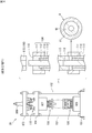
- FIG. 4 is a schematic configuration diagram showing an example of the molding apparatus 31 used in the molding step P1.
- the molding apparatus 31 used in the molding step P1 includes, for example, a uniaxially pressurized press molding apparatus driven by a hydraulic servo system.
- the press forming apparatus 31 was vertically and vertically supported by a rectangular base plate 101, columns 102 provided at the four corners of the base plate 101, a ceiling frame 103 fixed to the upper end of the columns 102, and an upper portion of the columns 102. It is provided with an upper plate 104.
- a punch set 106 whose vertical position is controlled by the hydraulic cylinder mechanism 105 is provided above the base plate 101, and a punch set 108 whose vertical position is controlled by the hydraulic cylinder mechanism 107 is provided below the upper plate 104. It is provided.
- a hydraulically driven upper cylinder 109 is provided at the center of the ceiling frame 103.
- the lower end of the rod of the upper cylinder 109 and the upper surface of the upper plate 104 are connected via a link mechanism 110. Therefore, when the upper cylinder 109 is extended, the upper plate 104 is lowered to the preparation position of the raw material powder 116. After that, the punch set 106 and the punch set 108 are joined by driving the upper and lower hydraulic cylinder mechanisms 105 and 107, and the raw material powder 116 is pressurized.
- the upper and lower hydraulic cylinder mechanisms 105 and 107 have a structure in which a plurality of hydraulic cylinders are multilayered in a coaxial center shape, and the axial center of each hydraulic cylinder is located at the center position of the base plate 101. Therefore, the press forming apparatus 31 has a slim structure in which there is no member protruding to the outside of the base plate 101, and can be installed without pits. Therefore, the press forming apparatus 31 has an advantage that the installation area and the installation cost are small.
- the lower punch set 106 includes a cylindrical die 111, a core rod 112, an outer punch 113, and an inner punch 114.
- a cavity is formed by the inner peripheral surface of the die 111 and the outer peripheral surface of the core rod 112.
- the upper punch set 108 includes an upper punch 115.
- the upper punch 115 has a cylindrical shape having a through hole for the core rod 112.
- the upper end surface of the core rod 112 is projected from the upper end surface of the die 111, and the outer punch 113 is set at a position deeper than the inner punch 114.
- the cavity is filled with the raw material powder 116.
- the upper punch 115 is lowered while the outer punch 113 and the lower punch 114 are raised together.
- the ascending speed is controlled so that the outer punch 113 and the inner punch 114 reach the top dead center at the same position at the same time.
- the outer peripheral portion having a large filling amount of the raw material powder 116 is compressed at a higher pressure than the inner peripheral portion having a small filling amount.
- a powder compact M having a uniform thickness is molded. Therefore, the powder compact M is a substantially donut-shaped tablet having a high-density region M1 on the outer peripheral portion and a low-density region M2 on the inner peripheral portion.
- the above molding method is suitable for manufacturing a sintered body S having continuous sliding portions on the outer peripheral edge, such as an external tooth gear and a sprocket. For example, in the case of an external tooth gear, by setting the outer peripheral side of the dust compact M to the high density region M1, an external tooth having high rigidity and excellent wear resistance can be obtained.
- the inner punch 114 is set at a position deeper than the outer punch 113 and the raw material powder 116 is press-molded, the inner peripheral portion is the high density region M1 and the outer peripheral portion is the low density region M2.
- the powder compact M is obtained.
- the above molding method is suitable for manufacturing a sintered body S having continuous sliding portions on the inner peripheral edge, such as an internal tooth gear.
- an internal tooth gear by setting the inner peripheral side of the powder compact M to the high-density region M1, an internal tooth having high rigidity and excellent wear resistance can be obtained.
- the relative density of the high density region M1 may be 93% or more, and the relative density of the low density region M2 is 93%. It may be less than. If the outer punch 113 and the inner punch 114 are set at the same depth position and the raw material powder 116 is press-molded, the powder compacted product having an overall average relative density of 93% or more using the press molding apparatus 31. M can also be molded.
- FIG. 5 is a schematic configuration diagram showing an example of the processing apparatus 32 used in the processing step P2.
- the processing device 32 used in the processing step P2 includes, for example, a robot processing device that processes the powder compact M using the articulated robots 201 and 202. Since the installation space of such a robot processing device 32 is smaller than that of, for example, a 5-axis machining center, it contributes to the compactification of the manufacturing equipment 3 for the sintered body S.
- the robot processing device 32 of the present embodiment includes two articulated robots 201 and 202 and a control device 203 that controls the operation of both articulated robots 201 and 202.
- the first robot 201 is a robot that holds a tool 204 such as a drill.
- the other second robot 202 is a robot that holds the powder compact M.
- the first robot 201 has a grip portion 205 of the tool 204 at the tip end portion of the arm.
- the first robot 201 can grip different types of tools 204 by the grip portion 205 in response to a command from the control device 203.
- the second robot 202 has a grip portion 206 of the dust compact M at the tip of the arm.
- the second robot 202 can grip the powder compact M being conveyed to the conveyor 36 by the grip portion 206.
- the second robot 202 can also return the processed molded product P to the conveyor 36.
- the control device 203 includes a first communication unit 207, a second communication unit 208, a control unit 209, and a storage unit 210.
- the first communication unit 207 includes a communication interface that communicates with an external device in accordance with a predetermined communication standard such as Ethernet (registered trademark).
- the second communication unit 208 includes a communication interface communicably connected to the first and second arms 201 and 202.
- the control unit 209 includes an information processing device including a CPU and a volatile memory.
- the storage unit 210 includes a storage device including a recording medium such as an HDD (Hard Disk Drive) or an SSD (Solid State Drive).
- HDD Hard Disk Drive
- SSD Solid State Drive
- the control unit 209 outputs each extracted operation code to the second communication unit 208 in order, and causes the articulated robots 201 and 202 to transmit the code.
- the articulated robots 201 and 202 perform a predetermined operation according to the received operation code.
- the articulated robots 201 and 202 perform predetermined processing on the powder compact M in response to a command from the control device 203.
- the first and second robots 201 and 202 have an arm structure having at least 6 degrees of freedom so that both the position and the posture of the work object (tool 204 and powder compact M) can be adjusted in three dimensions. Is preferable. However, when it is not necessary to adjust the position and posture with a high degree of freedom, such as holding the powder compact M at the same position during processing, a second robot 202 with a degree of freedom of less than 6 is adopted. May be good.
- the relative density of the dust compact M is 93% or more, the dust compact M held by the second robot 202 is cut by the tool 204 of the first robot 201. However, the powder compact M is not broken. Therefore, the powder compact M can be processed quickly. Further, since the first robot 201 has at least 6 degrees of freedom, the tool 204 can be brought into contact with the powder compact M at an arbitrary angle, and complicated machining can be performed quickly.
- FIG. 6 is a schematic configuration diagram showing an example of the sintering apparatus 33 used in the sintering step P3.
- the sintering apparatus 33 used in the sintering step P3 is, for example, from an induction heating sintering furnace that heats a processed dust compact M (processed molded product P) by a high frequency induction method. Become. Since the heating by the high frequency guidance method can raise the temperature of the object at high speed, the processed molded product P can be raised to a predetermined temperature in a short time. Therefore, the sintered body S can be easily manufactured in a short time.
- the induction heating sintering furnace 33 includes a vertically long chamber 301, a cylindrical heating container 302 housed in the chamber 301, and a cooling container 303 arranged below the heating container 302. It is provided with an elevating table 304 arranged below the heating container 302. An induction coil 305 is wound around the outer peripheral surface of the heating container 302, and the inside of the heating container 302 and the inside of the cooling container 303 communicate with each other in the vertical direction.
- the elevating table 304 can raise and lower the processed molded product P to either the inside of the heating container 302 or the inside of the cooling container 303.
- the induction heating sintering furnace 33 also includes a power source (not shown) whose output value (for example, electric power value) and frequency with respect to the induction coil 305 can be adjusted.
- the processed molded body P is placed on the elevating table 304 by the robot arm 37.
- the elevating table 304 positions the processed molded product P inside the heating container 302.
- the elevating table 304 positions the processed molded product P after sintering inside the cooling container 303.
- the induction heating sintering furnace 33 preferably includes a gas supply path for supplying an inert gas inside the heating container 302 and a gas discharge path for discharging the gas to the outside of the heating container 302.
- the processed molded product P can be sintered under a non-oxidizing gas atmosphere.
- the inert gas include nitrogen gas and argon gas.
- the induction heating sintering furnace 33 can raise the temperature of the object at high speed and raise the processed molded product P to a predetermined temperature in a short time. Therefore, there is an advantage that the sintered body S can be manufactured in a short time as compared with, for example, a belt type continuous sintering furnace. Since the induction heating sintering furnace 33 has a high heating rate, there is an advantage that a narrow installation space is sufficient as compared with, for example, a belt type continuous sintering furnace. In the case of the induction heating sintering furnace 33, for example, a relatively small chamber 301 (for example, 1.5 m ⁇ 1.5 m) can be adopted.
- the induction heating sintering furnace 33 requires only a short time to sinter the processed molded product P, and it is not necessary to keep the temperature of the sintered furnace 33 while the processed molded product P is not sintered. Therefore, there is an advantage that energy saving can be achieved as compared with, for example, a belt type continuous sintering furnace.
- a heating process, a sintering process, and a cooling process are performed in this order.
- a preferable temperature passage will be described when the induction heating sintering furnace 33 is used.
- Heating process In the temperature raising process, the temperature of the processed molded product P is controlled so as to satisfy all of the following conditions (I) to (III).
- the A1 point is about 738 ° C, and the A3 point is about 910 ° C.
- the temperature is raised in a temperature range of A1 point or more in the Fe—C phase diagram and lower than the sintering temperature of the processed molded product P without maintaining the temperature.
- the temperature rise rate in the temperature range from point A1 to point A3 in the Fe—C system phase diagram is set to 12 ° C./sec or more.
- the rate of temperature rise from point A3 in the Fe—C phase diagram to the sintering temperature of the processed molded product P is set to 4 ° C./sec or more.
- condition (ii) is satisfied from the following condition (i). This is because the condition (I) to the condition (III) and the condition (i) to the condition (iii) are substantially correlated. That is, if the condition (i) to the condition (iii) are satisfied, the temperature is controlled so as to satisfy the condition (I) to the condition (III).
- the temperature is raised in the atmospheric temperature range corresponding to the point A1 or more of the Fe—C system phase diagram and lower than the sintering temperature of the processed molded product P without maintaining the atmospheric temperature.
- the rate of temperature rise in the atmospheric temperature range corresponding to points A1 to A3 of the Fe—C phase diagram is set to 12 ° C./sec or more.
- the rate of temperature rise in the atmospheric temperature range corresponding to the point A3 of the Fe—C phase diagram to the sintering temperature of the processed molded product P is set to 4 ° C./sec or more.
- the ambient temperature is the ambient temperature inside the heating container 302, and is the temperature measured by a thermocouple (diameter ⁇ 3.5 mm) arranged within 8.5 mm from the processed molded product P. Since the atmosphere inside the heating container 302 is heated by the heat of the induction-heated processed molded product P, the ambient temperature is often slightly lower than the temperature of the induced-heated processed molded product P itself. ..
- the atmospheric temperature corresponding to the A1 point is the temperature of the atmosphere when the temperature of the processed molded product P reaches the A1 point, and is often the temperature of the A1 point or less. The same applies to the atmospheric temperature corresponding to the A3 point and the atmospheric temperature corresponding to the sintering temperature of the processed molded product P.
- the high-strength sintered body S can be produced.
- the reason is considered to be as follows. In the temperature range of condition (I), C is likely to diffuse into Fe, but by not maintaining the temperature in this temperature range and setting the temperature rise rate to a high speed as in conditions (II) and (III), C Diffusion into Fe is suppressed.
- the C particles adjacent to the Fe particles remain in a solid phase, and the adjacent interface between the Fe particles and the C particles becomes a C-rich phase (may be only C).
- the C-rich phase remains on the surface of Fe, it becomes a liquid phase of Fe—C at the sintering temperature.
- the Fe—C system phase diagram when C is about 0.2% by mass or more, the Fe—C system material becomes a liquid phase at 1153 ° C. or higher. Therefore, if the processed molded product P has a sintering temperature of 1153 ° C. or higher, the C-rich phase becomes a liquid phase.
- the rate of temperature rise can be adjusted by adjusting the output and frequency of the power supply of the induction heating sintering furnace 33.
- the output and frequency may be set, for example, to set the output and frequency that satisfy the temperature rising rate of the condition (II).
- the output and frequency settings may be constant from the temperature range of the condition (II) to the temperature range of the condition (III), or when shifting from the temperature range of the condition (II) to the temperature range of the condition (III). You may change it to.
- the temperature rising rate of the condition (III) can be satisfied. However, if the output and frequency are constant, the rate of temperature rise in condition (III) is slower than the rate of temperature rise in condition (II). If the output and frequency settings are changed when shifting from the temperature range of condition (II) to the temperature range of condition (III), the heating rate of condition (III) can be further increased, and by extension, the temperature range of condition (II) can be increased. It can be about the same as the rate of temperature rise.
- the upper limit of the temperature rising rate of the condition (II) is, for example, 50 ° C./sec or less, and more preferably 15 ° C./sec or less.
- the rate of temperature rise in the condition (III) is preferably as high as possible, for example, 5 ° C./sec or more, and further preferably 10 ° C./sec or more.
- the upper limit of the temperature rising rate of the condition (III) is, for example, 50 ° C./sec or less, and more preferably 15 ° C./sec or less.
- the temperature raising process it is preferable to further control the temperature of the processed molded product P so as to satisfy either the condition (IV) or the condition (V).
- the temperature In a temperature range in which the processed molded product P is 410 ° C. or higher and lower than the A1 point in the Fe—C phase diagram, the temperature is not maintained, and the temperature rising rate in this temperature range is 12 ° C./sec or higher.
- the temperature in the temperature range where the processed molded product P is 410 ° C. or higher and lower than the A1 point in the Fe—C system phase diagram is maintained for 30 seconds or more and 90 seconds or less.
- the temperature is controlled so as to satisfy either the condition (IV) or the condition (V), either the following condition (iv) or the condition (v) is satisfied. This is because the condition (IV) and the condition (V) and the condition (iv) and the condition (v) are substantially correlated. That is, if either the condition (iv) or the condition (v) is satisfied, the temperature is controlled so that either the condition (IV) or the condition (V) is satisfied.
- the temperature rise rate in this atmospheric temperature range is set to 12 ° C./sec or more without maintaining the atmospheric temperature of 400 ° C. or higher and lower than 700 ° C.
- the atmospheric temperature of 400 ° C. or higher and lower than 700 ° C. is maintained for 30 seconds or more and 90 seconds or less.
- the sintered body S having high strength can be produced in a short time as compared with the case where the condition (V) and the condition (v) are satisfied.
- the temperature rise rate of the condition (IV) and the condition (iv) can be achieved, for example, by setting the output and the frequency to be the same as the output and the frequency satisfying the temperature rise rate of the condition (II) and the condition (ii). ..
- the power output and frequency setting of the induction heating sintering furnace 33 are always constant from the start of temperature rise to the time of sintering, and the atmosphere temperature from the start of temperature rise to the atmosphere temperature at the time of sintering is set. It is mentioned not to hold.
- the rate of temperature rise at the ambient temperature of the condition (IV) and the condition (iv) is more preferably 15 ° C./sec or more, and particularly preferably 20 ° C./sec or more.
- the heat of the processed molded product P can be easily equalized as compared with the case where the condition (IV) and the condition (iv) are satisfied. That is, the condition (V) and the condition (v) are particularly suitable for sintering the processed molded product P having a complicated shape. Further, even if the condition (V) and the condition (v) are satisfied, a high-strength sintered body S can be obtained.
- the temperature range of the condition (V) is more preferably 735 ° C. or lower, and particularly preferably 700 ° C. or lower.
- the atmospheric temperature under the condition (v) is more preferably 600 ° C. or lower, and particularly preferably 500 ° C. or lower.
- the holding time for maintaining the atmospheric temperature under the condition (V) and the condition (v) is preferably 45 seconds or more and 75 seconds or less.
- the temperature rise rate after maintaining the temperature of the condition (V) and the atmospheric temperature of the condition (v) shall be the temperature rise rate of the condition (II), the condition (ii), the condition (III), and the condition (iii).
- the holding time of the processed molded product P at the atmospheric temperature (sintering temperature) at the time of sintering depends on the atmospheric temperature (sintering temperature) and the size of the molded product, but is preferably 30 seconds or more and 90 seconds or less, for example.
- the holding time is 30 seconds or more, the processed molded product P can be sufficiently heated, and a high-strength sintered body S can be easily produced.
- the holding time is 90 seconds or less, the holding time is short, so that the sintered body S can be manufactured in a short time.
- the holding time is further preferably less than 90 seconds, particularly preferably 60 seconds or less. In the case of a processed molded product P having a large size, it may be effective to set the holding time to 90 seconds or more.
- the sintering temperature of the heat-molded article P may be set to a temperature equal to or higher than the temperature at which the liquid phase of Fe—C is formed, and may be 1153 ° C. or higher.
- the sintering temperature is preferably 1250 ° C. or lower, for example. In this case, the temperature is not too high, excessive formation of the liquid phase can be suppressed, and it is easy to manufacture the sintered body S having high dimensional accuracy.
- the sintering temperature is further preferably 1153 ° C. or higher and 1200 ° C. or lower, and particularly preferably 1155 ° C. or higher and 1185 ° C. or lower.
- the ambient temperature of the processed molded product P during sintering is preferably 1135 ° C. or higher and lower than 1250 ° C. If the sintering temperature of the processed molded product P satisfies 1153 ° C. or higher, the atmospheric temperature of the processed molded product P at the time of sintering satisfies 1135 ° C. or higher. Similarly, if the sintering temperature of the processed molded product P is 1250 ° C. or lower, the atmospheric temperature of the processed molded product P at the time of sintering is less than 1250 ° C.
- the ambient temperature at the time of sintering is further preferably 1135 ° C. or higher and 1185 ° C. or lower, and particularly preferably 1135 ° C. or higher and lower than 1185 ° C.
- the temperature lowering rate in the cooling process of the sintering step P3 is preferably increased.
- the temperature lowering rate is preferably 1 ° C./sec or higher. As a result, it can be cooled quickly.
- the temperature lowering rate is further preferably 2 ° C./sec or higher, and particularly preferably 5 ° C./sec or higher.
- the temperature lowering rate is, for example, 200 ° C./sec or less, further 100 ° C./sec or less, and particularly 50 ° C./sec or less.
- the temperature range for cooling at this cooling rate may be a temperature range from the start of cooling (sintering temperature of the processed molded product P) to the completion of cooling (for example, about 200 ° C.).
- the temperature (atmospheric temperature) of the processed molded product P is in a temperature range (atmospheric temperature range) from 750 ° C. (700 ° C.) to 230 ° C. (200 ° C.).
- the cooling method include blowing a cooling gas onto the sintered body S.
- the cooling gas include an inert gas such as nitrogen gas and argon gas. Due to the rapid temperature drop, the heat treatment process in the subsequent process can be omitted.
- FIG. 7 is a schematic configuration diagram showing an example of the inspection device 35 used in the inspection step P5.
- the inspection device 35 used in the inspection step P5 includes first and second sensor devices 501 and 502, and a computer device 503 communicatively connected to each of the sensor devices 501 and 502. .
- the computer device 503 includes, for example, a desktop personal computer (PC).
- the type of computer device 503 is not particularly limited.
- the type of the computer device 503 may be, for example, a notebook type or a tablet type.
- the computer device 503 is composed of an information processing device including a CPU and a volatile memory, and a storage device including a non-volatile memory for storing a computer program executed by the CPU and data necessary for the execution thereof.
- the computer device 2 also includes an input device and a display.
- the computer device 503 functions as a predetermined control device when the CPU reads the computer program into the volatile memory and executes it.
- the first sensor device 501 comprises, for example, a non-contact 3D scanner.
- the 3D scanner may be the pattern light type 3D scanner 1 (see FIG. 2) described above, or may be a laser light type 3D scanner.
- the first sensor device 501 scans the sintered bodies S that have undergone the finishing step P4 one by one to generate three-dimensional CAD data, and transmits the generated data to the computer device 503.
- the second sensor device 502 includes, for example, a digital camera capable of acquiring a digital image.
- the second sensor device 502 photographs the sintered bodies S that have undergone the finishing step P4 one by one to generate image data, and transmits the generated image data to the computer device 503.
- the computer device 503 stores the three-dimensional CAD data of the current product C. This data is, for example, the data received from the computer device 2 in step 2 or the data stored in the computer device 503 via a recording medium such as a USB memory.
- the computer device 503 calculates the dimensional error of both based on the three-dimensional CAD data of the sintered body S and the three-dimensional CAD data of the current product C, and determines the pass / fail of the sintered body S based on the calculated dimensional error. .. Specifically, the sintered body S having a dimensional error of less than or equal to a predetermined value is regarded as acceptable, and the sintered body S having a dimensional error exceeding a predetermined value is regarded as rejected (defective). Further, the computer device 503 transmits the three-dimensional CAD data of the sintered body S determined to be acceptable to the computer device 4 used in step 4.
- the computer device 503 determines the presence or absence of cracks or scratches on the surface based on the image data acquired from the second sensor device 502, and determines that the sintered body S having cracks or scratches is rejected (defective).
- the cracked or scratched sintered body S is excluded as a defective product.
- the determination process can be performed, for example, depending on whether or not the partial image obtained by dividing the image data into a grid pattern is included in a target event such as a scratch included in the classification model obtained by machine learning (Japanese Patent Laid-Open No. 2018-). 81629 (see).
- the powder compact M having a simple shape and high density is produced by uniaxial pressurization, and the powder compact M is processed by the robot processing apparatus 32 having a high degree of processing freedom.
- the processed molded product P is produced by the above method, and the processed molded product P is sintered to produce a sintered body S. Therefore, the high-precision sintered body S can be manufactured without using a mold having a complicated shape, which requires several months to manufacture. Therefore, the delivery time of the sintered body S can be shortened.
- the induction heating sintering furnace 33 capable of producing the sintered body S in a shorter time than the belt type continuous sintering furnace is adopted. Therefore, in this respect as well, the sintered body S of the sintered body S is used. The delivery time can be shortened.
- the robot processing device 32 which has a smaller installation space than the 5-axis machining center, and the induction heating sintering furnace 33, which has a smaller installation space than the belt-type continuous sintering furnace, are used. There is also an advantage that the manufacturing facility 3 can be made compact.
- FIG. 8 is an explanatory diagram showing an example of the apparatus used in step 4.
- the device used in step 4 comprises a computer device 4.
- the computer device 2 includes, for example, a desktop personal computer (PC).
- the type of the computer device 2 is not particularly limited.
- the type of the computer device 2 may be, for example, a notebook type or a tablet type.
- the computer device 4 is composed of an information processing device including a CPU and a volatile memory, a storage device including a non-volatile memory for storing a computer program executed by the CPU and data necessary for the execution thereof, and the like.
- the computer device 2 also includes an input device and a display.
- the computer device 4 functions as a predetermined control device when the CPU reads the computer program into the volatile memory and executes it.
- the CAD / CAT software is installed in the computer device 4.
- the CAD / CAT software uses the three-dimensional CAD data of the determination target (here, the sintered body S that has passed the inspection of the inspection step P5) and the sintered body S according to the user's operation input to the GUI of the computer device 4. It is software that realizes comparison processing with the design data (three-dimensional CAD data of the current product C) that is the reference of the shape of.
- the computer device 4 receives the three-dimensional CAD data of the plurality of sintered bodies S from the computer device 503 of the inspection step P5.
- the computer device 4 stores the three-dimensional CAD data of the current product C.
- This data is, for example, the data received from the computer device 2 in step 2, the data received from the computer device 503 in the inspection step P5, or the data stored in the computer device 4 via a recording medium such as a USB memory.
- the computer device 4 Based on the comparison result of the 3D data of the plurality of sintered bodies C and the 3D data of the current product C, the computer device 4 has detected as many over-cut or under-cut locations as statistically superior. Is determined.
- the computer device 4 detects a portion that is over-cut or under-cut, it generates a modification program (for example, NC program) of a machining program.
- the modification program includes, for example, an operation code for deepening the cut depth of the over-cut portion, or an operation code for deepening the cut depth of the under-cut portion.
- the computer device 4 transmits the generated modification program to the processing device 32 used in the processing step P2 of step 3.
- the molded product processing apparatus 32 that has received the modification program processes the powder compact M at the modified depth of cut.
- the computer device 4 may transmit the modification program to the computer device 2 (see FIG. 2) in step 2.
- the computer device 2 in step 2 may transfer the received modification program to the processing device 32.
- the molding apparatus 31 used in the molding step P1 of step 3 may be a press molding apparatus for molding the powder compact M having an overall average relative density of less than 93%.
- the processing apparatus 32 used in the processing step P2 of step 3 may be a robot processing apparatus including only the first robot 201. In this case, the first robot 201 performs a predetermined process on the powder compact M set on the fixed base.
- the processing apparatus 32 used in the processing step P2 of step 3 may be a robot processing apparatus provided with at least one of the first and second robots 201 and 202. That is, the number of the first and second robots 201 and 202 may be plural.
- the processing apparatus 32 used in the processing step P2 of step 3 may be a processing apparatus that employs a 5-axis machining center instead of the articulated robots 201 and 202.
- the sintering apparatus 33 used in the sintering step P3 of step 3 may be a belt-type continuous sintering furnace instead of the induction heating sintering furnace.
- the inspection step P5 in step 3 is not limited to the case where the inspection device 35 is used to perform the inspection step P5 fully automatically, and a human may perform all or part of the inspection work.
- the inspection step P5 of step 3 may include modification of the machining program of step 4. That is, the computer device 503 in the inspection step P5 may execute the arithmetic processing and the communication processing performed by the computer device 4 in step 4. In this case, the computer device 4 in step 4 becomes unnecessary.
- FIG. 9 is a schematic configuration diagram showing an example of a movable manufacturing system.
- the manufacturing system according to the second modification includes a mobile device 601 that can pass through a road and a predetermined storage element that is stored in the storage 602 of the mobile device 601.
- the predetermined storage element is a component required for manufacturing the sintered body S.
- the moving device 601 is composed of, for example, a large truck
- the storage 602 is composed of a container fixed to the loading platform of the large truck.
- the predetermined storage elements include a 3D scanner 1 used in step 1, a computer device 2 used in step 2, and a robot processing device 32 used in the processing step P2 of step 3. Including the induction heating sintering furnace 33 used in the sintering step P3 of step 3.
- the sintered body S can be manufactured by the following procedure. Therefore, it becomes possible to provide the sintered body S (test product) following the current product C to the customer in a short time (for example, several hours).
- Step 1 The mobile device 601 is mounted to a nearby point of the customer's residence, and a predetermined storage element mounted on the storage 602 is transported to the nearby point.
- Step 2 Get the current product C from the customer.
- Step 3 Perform steps 1 to 3 to locally manufacture a sintered body S that follows the current product C.
- Step 4 Provide the manufactured sintered body S (sample) to the customer.
- the powder compact M to be processed by the robot processing device 32 may be manufactured in advance by the manufacturer at its own factory and loaded into the moving device 601.
- the 3D scanner 1 may be excluded from the predetermined storage elements.
- the 3D data generated by the 3D scanner 1 outside the vehicle may be transmitted to the computer device 2 inside the vehicle.
- the 3D data of the current product C acquired from the customer or the like may be transmitted to the computer device 2 in the vehicle.
- the computer device 2 may be excluded from the predetermined storage elements.
- the computer device 2 outside the vehicle may generate a molded body processing program from the 3D data of the current product C, and transmit the generated program to the robot processing device 32 inside the vehicle.
- the molding apparatus 31 used in the molding step P1 of step 3 may be included in the predetermined storage element.
- the compaction compact M can also be molded on-site.
- the apparatus (polishing apparatus or the like) used in the finishing step P4 of step 3 may be included in the predetermined storage element. In this case, the finishing of the sintered body S can also be performed on-site.
- the inspection device 35 used in the inspection step P5 of step 3 may be included in the predetermined storage element. In this case, inspections such as pass / fail judgment of the sintered body S can also be performed on-site.
- the device (computer device 4) used in step 4 may be included in a predetermined storage element. In this case, the machining program in step 4 can be modified locally.
- the target product that serves as a reference for the shape of the sintered product S is not limited to the existing current product C, and is under planning that has not yet been commercialized. It may be an item of.
Landscapes
- Engineering & Computer Science (AREA)
- Manufacturing & Machinery (AREA)
- Mechanical Engineering (AREA)
- Powder Metallurgy (AREA)
Abstract
L'invention concerne, selon un mode de réalisation, un système de fabrication comprenant : un dispositif de moulage permettant de fabriquer un moulage par compression de poudre, la densité relative de l'ensemble ou d'une partie étant d'au moins 93 %, par compression uniaxiale d'une poudre de matière première qui comprend de la poudre métallique ; un dispositif de traitement robotisé qui a un robot articulé et qui fabrique un moulage traité par traitement mécanique du moulage par compression de poudre ; et un four de frittage par induction permettant de fabriquer un compact fritté par frittage du moulage traité à l'aide d'un chauffage par induction à haute fréquence.
Priority Applications (5)
| Application Number | Priority Date | Filing Date | Title |
|---|---|---|---|
| US17/603,346 US20220176448A1 (en) | 2019-04-24 | 2019-04-24 | Manufacturing system and manufacturing method of sintered product |
| DE112019007258.7T DE112019007258T5 (de) | 2019-04-24 | 2019-04-24 | Fertigungssystem und Herstellungsverfahren für ein Sinterprodukt |
| PCT/JP2019/017351 WO2020217331A1 (fr) | 2019-04-24 | 2019-04-24 | Système de fabrication et procédé de fabrication d'un compact fritté |
| JP2021515367A JPWO2020217331A1 (ja) | 2019-04-24 | 2019-04-24 | 焼結体の製造システム及び製造方法 |
| CN201980094991.5A CN113646112A (zh) | 2019-04-24 | 2019-04-24 | 烧结体的制造系统及制造方法 |
Applications Claiming Priority (1)
| Application Number | Priority Date | Filing Date | Title |
|---|---|---|---|
| PCT/JP2019/017351 WO2020217331A1 (fr) | 2019-04-24 | 2019-04-24 | Système de fabrication et procédé de fabrication d'un compact fritté |
Publications (1)
| Publication Number | Publication Date |
|---|---|
| WO2020217331A1 true WO2020217331A1 (fr) | 2020-10-29 |
Family
ID=72941133
Family Applications (1)
| Application Number | Title | Priority Date | Filing Date |
|---|---|---|---|
| PCT/JP2019/017351 Ceased WO2020217331A1 (fr) | 2019-04-24 | 2019-04-24 | Système de fabrication et procédé de fabrication d'un compact fritté |
Country Status (5)
| Country | Link |
|---|---|
| US (1) | US20220176448A1 (fr) |
| JP (1) | JPWO2020217331A1 (fr) |
| CN (1) | CN113646112A (fr) |
| DE (1) | DE112019007258T5 (fr) |
| WO (1) | WO2020217331A1 (fr) |
Cited By (1)
| Publication number | Priority date | Publication date | Assignee | Title |
|---|---|---|---|---|
| KR102560783B1 (ko) * | 2022-12-16 | 2023-07-27 | (주)이에프씨 | 인조흑연 생산 자동화 장치 |
Families Citing this family (1)
| Publication number | Priority date | Publication date | Assignee | Title |
|---|---|---|---|---|
| US20250209607A1 (en) * | 2023-12-21 | 2025-06-26 | Pratt & Whitney Canada Corp. | Method to qualify additional dies after master die |
Citations (9)
| Publication number | Priority date | Publication date | Assignee | Title |
|---|---|---|---|---|
| JPS5964702A (ja) * | 1982-09-30 | 1984-04-12 | Toyota Motor Corp | 金属粉末の圧粉体における高周波焼結方法 |
| JPH02200703A (ja) * | 1989-01-27 | 1990-08-09 | Tokin Corp | 金属粉末焼結体の製造方法 |
| JPH07197104A (ja) * | 1994-01-10 | 1995-08-01 | Janome Sewing Mach Co Ltd | 精密粉末焼結品の製造方法 |
| WO2008103209A1 (fr) * | 2007-02-21 | 2008-08-28 | Lockheed Martin Corporation | Robot articulé pour inspection au laser-ultrasonore |
| JP2012218192A (ja) * | 2011-04-05 | 2012-11-12 | Nippon Shoryoku Kikai Kk | ワーク取り出し仕上げ装置 |
| JP2015001017A (ja) * | 2013-06-17 | 2015-01-05 | 一般財団法人ファインセラミックスセンター | 炭窒化物分散焼結体及びその製造方法 |
| JP2016113659A (ja) * | 2014-12-12 | 2016-06-23 | 住友電工焼結合金株式会社 | 焼結部品の製造方法、及び焼結部品 |
| WO2017146202A1 (fr) * | 2016-02-25 | 2017-08-31 | 大日本印刷株式会社 | Système de génération d'informations de données et de texture de forme tridimensionnelle, programme de commande photographique et procédé de génération d'informations de données et de texture de forme tridimensionnelle |
| WO2018163436A1 (fr) * | 2017-03-10 | 2018-09-13 | 飯田グループホールディングス株式会社 | Système embarqué de traitement de matériau de construction et procédé de traitement de matériau de construction |
Family Cites Families (10)
| Publication number | Priority date | Publication date | Assignee | Title |
|---|---|---|---|---|
| US6656416B2 (en) * | 2000-09-12 | 2003-12-02 | Sumitomo Special Metals Co., Ltd. | Powder feeding apparatus, pressing apparatus using the same, powder feeding method and sintered magnet manufacturing method |
| US20120176212A1 (en) * | 2009-08-28 | 2012-07-12 | Intermetallics Co., Ltd. | METHOD AND SYSTEM FOR PRODUCING SINTERED NdFeB MAGNET, AND SINTERED NdFeB MAGNET PRODUCED BY THE PRODUCTION METHOD |
| JP6306929B2 (ja) * | 2013-04-22 | 2018-04-04 | 住友化学株式会社 | 焼結体の製造方法 |
| JP6149718B2 (ja) * | 2013-12-16 | 2017-06-21 | 株式会社豊田中央研究所 | 鉄基焼結合金とその製造方法および高炭素鉄系粉末 |
| JP6346521B2 (ja) * | 2014-08-07 | 2018-06-20 | 住友電気工業株式会社 | 圧粉磁心、及びコイル部品 |
| JP6395217B2 (ja) | 2014-12-12 | 2018-09-26 | 住友電工焼結合金株式会社 | 焼結部品の製造方法 |
| JP6445858B2 (ja) * | 2014-12-12 | 2018-12-26 | 住友電工焼結合金株式会社 | 焼結部品の製造方法、及びドリル |
| JP6502765B2 (ja) * | 2015-06-29 | 2019-04-17 | 住友電工焼結合金株式会社 | 焼結体の製造装置、及び焼結体の製造方法 |
| JP6509771B2 (ja) | 2016-04-07 | 2019-05-08 | 住友電気工業株式会社 | 焼結体の製造方法 |
| JP6106323B1 (ja) * | 2016-07-07 | 2017-03-29 | Jfe精密株式会社 | 焼結タングステン基合金及びその製造方法 |
-
2019
- 2019-04-24 CN CN201980094991.5A patent/CN113646112A/zh active Pending
- 2019-04-24 DE DE112019007258.7T patent/DE112019007258T5/de not_active Withdrawn
- 2019-04-24 WO PCT/JP2019/017351 patent/WO2020217331A1/fr not_active Ceased
- 2019-04-24 JP JP2021515367A patent/JPWO2020217331A1/ja active Pending
- 2019-04-24 US US17/603,346 patent/US20220176448A1/en not_active Abandoned
Patent Citations (9)
| Publication number | Priority date | Publication date | Assignee | Title |
|---|---|---|---|---|
| JPS5964702A (ja) * | 1982-09-30 | 1984-04-12 | Toyota Motor Corp | 金属粉末の圧粉体における高周波焼結方法 |
| JPH02200703A (ja) * | 1989-01-27 | 1990-08-09 | Tokin Corp | 金属粉末焼結体の製造方法 |
| JPH07197104A (ja) * | 1994-01-10 | 1995-08-01 | Janome Sewing Mach Co Ltd | 精密粉末焼結品の製造方法 |
| WO2008103209A1 (fr) * | 2007-02-21 | 2008-08-28 | Lockheed Martin Corporation | Robot articulé pour inspection au laser-ultrasonore |
| JP2012218192A (ja) * | 2011-04-05 | 2012-11-12 | Nippon Shoryoku Kikai Kk | ワーク取り出し仕上げ装置 |
| JP2015001017A (ja) * | 2013-06-17 | 2015-01-05 | 一般財団法人ファインセラミックスセンター | 炭窒化物分散焼結体及びその製造方法 |
| JP2016113659A (ja) * | 2014-12-12 | 2016-06-23 | 住友電工焼結合金株式会社 | 焼結部品の製造方法、及び焼結部品 |
| WO2017146202A1 (fr) * | 2016-02-25 | 2017-08-31 | 大日本印刷株式会社 | Système de génération d'informations de données et de texture de forme tridimensionnelle, programme de commande photographique et procédé de génération d'informations de données et de texture de forme tridimensionnelle |
| WO2018163436A1 (fr) * | 2017-03-10 | 2018-09-13 | 飯田グループホールディングス株式会社 | Système embarqué de traitement de matériau de construction et procédé de traitement de matériau de construction |
Cited By (1)
| Publication number | Priority date | Publication date | Assignee | Title |
|---|---|---|---|---|
| KR102560783B1 (ko) * | 2022-12-16 | 2023-07-27 | (주)이에프씨 | 인조흑연 생산 자동화 장치 |
Also Published As
| Publication number | Publication date |
|---|---|
| US20220176448A1 (en) | 2022-06-09 |
| JPWO2020217331A1 (ja) | 2021-12-23 |
| DE112019007258T5 (de) | 2022-01-13 |
| CN113646112A (zh) | 2021-11-12 |
Similar Documents
| Publication | Publication Date | Title |
|---|---|---|
| US11813791B2 (en) | Method and system for producing a workpiece using additive manufacturing techniques | |
| Dutta et al. | Science, technology and applications of metals in additive manufacturing | |
| Everton et al. | Review of in-situ process monitoring and in-situ metrology for metal additive manufacturing | |
| Günther et al. | Fatigue life of additively manufactured Ti–6Al–4V in the very high cycle fatigue regime | |
| CN108746616B (zh) | 一种同轴送粉与激光锻打复合增减材制造方法及装置 | |
| Bremen et al. | Selective laser melting: a manufacturing technology for the future? | |
| Abdel Ghany et al. | Comparison between the products of four RPM systems for metals | |
| JP2006521842A (ja) | 歯科補綴を製造する方法 | |
| Stwora et al. | Influence of selected parameters of Selective Laser Sintering process on properties of sintered materials | |
| WO2013089279A4 (fr) | Procédé de génération de données d'usinage pour dispositif d'usinage combiné ultraprécis et dispositif d'usinage combiné ultraprécis | |
| Parenti et al. | Implementation of hybrid additive manufacturing based on extrusion of feedstock and milling | |
| Rodríguez et al. | Maximal reduction of steps for iron casting one-of-a-kind parts | |
| CN107876771A (zh) | 一种金属激光熔化增材制造方法 | |
| Borrelli et al. | Ti6Al4V parts produced by electron beam melting: analysis of dimensional accuracy and surface roughness | |
| JPWO2020217331A1 (ja) | 焼結体の製造システム及び製造方法 | |
| CN109514181B (zh) | 用于制造切削工具的方法和机器设备 | |
| JP2020504682A (ja) | 加工物成形装置および方法 | |
| CN103521767A (zh) | 一种复杂零件的高速精密加工方法和装置 | |
| Milewski et al. | Application of a manufacturing model for the optimization of additive processing of Inconel alloy 690 | |
| Kashapov et al. | Formation of cracks in the selective laser melting of objects from powdered stainless steel 17-4 PH | |
| Grobelny et al. | Investigations of Surface Topography of Hot Working Tool Steel Manufactured with the Use of 3D Print | |
| CN103949641A (zh) | 一种微孔拉丝模硬质合金模芯的制造工艺 | |
| Lackey | Comparative study of mechanical properties of 316L stainless steel between traditional production methods and selective laser melting | |
| Dabwan et al. | Effects of milling process parameters on cutting forces and surface roughness when finishing Ti6al4v produced by electron beam melting | |
| US20240058862A1 (en) | Build materials having a powder mixture comprising graphene, methods of producing articles therefrom, and articles produced therewith |
Legal Events
| Date | Code | Title | Description |
|---|---|---|---|
| 121 | Ep: the epo has been informed by wipo that ep was designated in this application |
Ref document number: 19926387 Country of ref document: EP Kind code of ref document: A1 |
|
| ENP | Entry into the national phase |
Ref document number: 2021515367 Country of ref document: JP Kind code of ref document: A |
|
| 122 | Ep: pct application non-entry in european phase |
Ref document number: 19926387 Country of ref document: EP Kind code of ref document: A1 |