WO2020218285A1 - 容量制御弁 - Google Patents
容量制御弁 Download PDFInfo
- Publication number
- WO2020218285A1 WO2020218285A1 PCT/JP2020/017169 JP2020017169W WO2020218285A1 WO 2020218285 A1 WO2020218285 A1 WO 2020218285A1 JP 2020017169 W JP2020017169 W JP 2020017169W WO 2020218285 A1 WO2020218285 A1 WO 2020218285A1
- Authority
- WO
- WIPO (PCT)
- Prior art keywords
- valve
- valve body
- pressure
- control
- axial direction
- Prior art date
- Legal status (The legal status is an assumption and is not a legal conclusion. Google has not performed a legal analysis and makes no representation as to the accuracy of the status listed.)
- Ceased
Links
Images






Classifications
-
- F—MECHANICAL ENGINEERING; LIGHTING; HEATING; WEAPONS; BLASTING
- F04—POSITIVE - DISPLACEMENT MACHINES FOR LIQUIDS; PUMPS FOR LIQUIDS OR ELASTIC FLUIDS
- F04B—POSITIVE-DISPLACEMENT MACHINES FOR LIQUIDS; PUMPS
- F04B27/00—Multi-cylinder pumps specially adapted for elastic fluids and characterised by number or arrangement of cylinders
- F04B27/08—Multi-cylinder pumps specially adapted for elastic fluids and characterised by number or arrangement of cylinders having cylinders coaxial with, or parallel or inclined to, main shaft axis
- F04B27/14—Control
- F04B27/16—Control of pumps with stationary cylinders
- F04B27/18—Control of pumps with stationary cylinders by varying the relative positions of a swash plate and a cylinder block
- F04B27/1804—Controlled by crankcase pressure
-
- F—MECHANICAL ENGINEERING; LIGHTING; HEATING; WEAPONS; BLASTING
- F04—POSITIVE - DISPLACEMENT MACHINES FOR LIQUIDS; PUMPS FOR LIQUIDS OR ELASTIC FLUIDS
- F04B—POSITIVE-DISPLACEMENT MACHINES FOR LIQUIDS; PUMPS
- F04B27/00—Multi-cylinder pumps specially adapted for elastic fluids and characterised by number or arrangement of cylinders
- F04B27/08—Multi-cylinder pumps specially adapted for elastic fluids and characterised by number or arrangement of cylinders having cylinders coaxial with, or parallel or inclined to, main shaft axis
- F04B27/14—Control
- F04B27/16—Control of pumps with stationary cylinders
- F04B27/18—Control of pumps with stationary cylinders by varying the relative positions of a swash plate and a cylinder block
-
- F—MECHANICAL ENGINEERING; LIGHTING; HEATING; WEAPONS; BLASTING
- F04—POSITIVE - DISPLACEMENT MACHINES FOR LIQUIDS; PUMPS FOR LIQUIDS OR ELASTIC FLUIDS
- F04B—POSITIVE-DISPLACEMENT MACHINES FOR LIQUIDS; PUMPS
- F04B49/00—Control, e.g. of pump delivery, or pump pressure of, or safety measures for, machines, pumps, or pumping installations, not otherwise provided for, or of interest apart from, groups F04B1/00 - F04B47/00
- F04B49/12—Control, e.g. of pump delivery, or pump pressure of, or safety measures for, machines, pumps, or pumping installations, not otherwise provided for, or of interest apart from, groups F04B1/00 - F04B47/00 by varying the length of stroke of the working members
-
- F—MECHANICAL ENGINEERING; LIGHTING; HEATING; WEAPONS; BLASTING
- F16—ENGINEERING ELEMENTS AND UNITS; GENERAL MEASURES FOR PRODUCING AND MAINTAINING EFFECTIVE FUNCTIONING OF MACHINES OR INSTALLATIONS; THERMAL INSULATION IN GENERAL
- F16K—VALVES; TAPS; COCKS; ACTUATING-FLOATS; DEVICES FOR VENTING OR AERATING
- F16K17/00—Safety valves; Equalising valves, e.g. pressure relief valves
- F16K17/02—Safety valves; Equalising valves, e.g. pressure relief valves opening on surplus pressure on one side; closing on insufficient pressure on one side
- F16K17/04—Safety valves; Equalising valves, e.g. pressure relief valves opening on surplus pressure on one side; closing on insufficient pressure on one side spring-loaded
-
- F—MECHANICAL ENGINEERING; LIGHTING; HEATING; WEAPONS; BLASTING
- F16—ENGINEERING ELEMENTS AND UNITS; GENERAL MEASURES FOR PRODUCING AND MAINTAINING EFFECTIVE FUNCTIONING OF MACHINES OR INSTALLATIONS; THERMAL INSULATION IN GENERAL
- F16K—VALVES; TAPS; COCKS; ACTUATING-FLOATS; DEVICES FOR VENTING OR AERATING
- F16K27/00—Construction of housing; Use of materials therefor
- F16K27/02—Construction of housing; Use of materials therefor of lift valves
- F16K27/029—Electromagnetically actuated valves
-
- F—MECHANICAL ENGINEERING; LIGHTING; HEATING; WEAPONS; BLASTING
- F16—ENGINEERING ELEMENTS AND UNITS; GENERAL MEASURES FOR PRODUCING AND MAINTAINING EFFECTIVE FUNCTIONING OF MACHINES OR INSTALLATIONS; THERMAL INSULATION IN GENERAL
- F16K—VALVES; TAPS; COCKS; ACTUATING-FLOATS; DEVICES FOR VENTING OR AERATING
- F16K31/00—Actuating devices; Operating means; Releasing devices
- F16K31/02—Actuating devices; Operating means; Releasing devices electric; magnetic
- F16K31/06—Actuating devices; Operating means; Releasing devices electric; magnetic using a magnet, e.g. diaphragm valves, cutting off by means of a liquid
- F16K31/0644—One-way valve
- F16K31/0655—Lift valves
-
- F—MECHANICAL ENGINEERING; LIGHTING; HEATING; WEAPONS; BLASTING
- F04—POSITIVE - DISPLACEMENT MACHINES FOR LIQUIDS; PUMPS FOR LIQUIDS OR ELASTIC FLUIDS
- F04B—POSITIVE-DISPLACEMENT MACHINES FOR LIQUIDS; PUMPS
- F04B27/00—Multi-cylinder pumps specially adapted for elastic fluids and characterised by number or arrangement of cylinders
- F04B27/08—Multi-cylinder pumps specially adapted for elastic fluids and characterised by number or arrangement of cylinders having cylinders coaxial with, or parallel or inclined to, main shaft axis
- F04B27/14—Control
- F04B27/16—Control of pumps with stationary cylinders
- F04B27/18—Control of pumps with stationary cylinders by varying the relative positions of a swash plate and a cylinder block
- F04B27/1804—Controlled by crankcase pressure
- F04B2027/1809—Controlled pressure
- F04B2027/1813—Crankcase pressure
-
- F—MECHANICAL ENGINEERING; LIGHTING; HEATING; WEAPONS; BLASTING
- F04—POSITIVE - DISPLACEMENT MACHINES FOR LIQUIDS; PUMPS FOR LIQUIDS OR ELASTIC FLUIDS
- F04B—POSITIVE-DISPLACEMENT MACHINES FOR LIQUIDS; PUMPS
- F04B27/00—Multi-cylinder pumps specially adapted for elastic fluids and characterised by number or arrangement of cylinders
- F04B27/08—Multi-cylinder pumps specially adapted for elastic fluids and characterised by number or arrangement of cylinders having cylinders coaxial with, or parallel or inclined to, main shaft axis
- F04B27/14—Control
- F04B27/16—Control of pumps with stationary cylinders
- F04B27/18—Control of pumps with stationary cylinders by varying the relative positions of a swash plate and a cylinder block
- F04B27/1804—Controlled by crankcase pressure
- F04B2027/1822—Valve-controlled fluid connection
- F04B2027/1831—Valve-controlled fluid connection between crankcase and suction chamber
-
- F—MECHANICAL ENGINEERING; LIGHTING; HEATING; WEAPONS; BLASTING
- F04—POSITIVE - DISPLACEMENT MACHINES FOR LIQUIDS; PUMPS FOR LIQUIDS OR ELASTIC FLUIDS
- F04B—POSITIVE-DISPLACEMENT MACHINES FOR LIQUIDS; PUMPS
- F04B27/00—Multi-cylinder pumps specially adapted for elastic fluids and characterised by number or arrangement of cylinders
- F04B27/08—Multi-cylinder pumps specially adapted for elastic fluids and characterised by number or arrangement of cylinders having cylinders coaxial with, or parallel or inclined to, main shaft axis
- F04B27/14—Control
- F04B27/16—Control of pumps with stationary cylinders
- F04B27/18—Control of pumps with stationary cylinders by varying the relative positions of a swash plate and a cylinder block
- F04B27/1804—Controlled by crankcase pressure
- F04B2027/184—Valve controlling parameter
- F04B2027/185—Discharge pressure
-
- F—MECHANICAL ENGINEERING; LIGHTING; HEATING; WEAPONS; BLASTING
- F04—POSITIVE - DISPLACEMENT MACHINES FOR LIQUIDS; PUMPS FOR LIQUIDS OR ELASTIC FLUIDS
- F04B—POSITIVE-DISPLACEMENT MACHINES FOR LIQUIDS; PUMPS
- F04B27/00—Multi-cylinder pumps specially adapted for elastic fluids and characterised by number or arrangement of cylinders
- F04B27/08—Multi-cylinder pumps specially adapted for elastic fluids and characterised by number or arrangement of cylinders having cylinders coaxial with, or parallel or inclined to, main shaft axis
- F04B27/14—Control
- F04B27/16—Control of pumps with stationary cylinders
- F04B27/18—Control of pumps with stationary cylinders by varying the relative positions of a swash plate and a cylinder block
- F04B27/1804—Controlled by crankcase pressure
- F04B2027/184—Valve controlling parameter
- F04B2027/1854—External parameters
Definitions
- the present invention relates to a capacity control valve that variably controls the capacity of a working fluid, for example, a capacity control valve that controls the discharge amount of a variable capacity compressor used in an automobile air conditioning system according to pressure.
- Variable-capacity compressors used in air conditioning systems such as automobiles include a rotating shaft that is rotationally driven by an engine, a swash plate that is variably connected to a rotation axis at an inclination angle, and a compression piston that is connected to the sloping plate.
- the inclination angle of the swash plate is determined by the suction pressure Ps of the suction chamber that sucks the fluid, the discharge pressure Pd of the discharge chamber that discharges the fluid pressurized by the piston, using the capacitance control valve that is driven to open and close by electromagnetic force. It is possible to continuously change the pressure in the control chamber by appropriately controlling the pressure in the control chamber while utilizing the control pressure Pc in the control chamber containing the swash plate.
- the capacitance control valve When the capacitance variable compressor is continuously driven, the capacitance control valve is energized and controlled by a control computer, and the valve body is moved in the axial direction by the electromagnetic force generated by the solenoid, and the discharge port through which the discharge fluid of the discharge pressure Pd passes. Normal control is performed to adjust the control pressure Pc in the control chamber of the variable capacitance compressor by opening and closing the DC valve provided between the control pressure Pc and the control port through which the control fluid of the control pressure Pc passes.
- the pressure in the control chamber of the variable capacitance compressor is appropriately controlled, and the stroke amount of the piston is changed by continuously changing the inclination angle of the swash plate with respect to the rotation axis.
- the amount of fluid discharged to the discharge chamber is controlled so that the air conditioning system has the target cooling capacity.
- the capacitance control valve of Patent Document 1 controls the fluid of the discharge pressure Pd supplied to the control chamber of the variable capacitance compressor by opening and closing the DC valve, and has the discharge pressure Pd of the discharge chamber acting in the stroke direction of the piston.
- the discharge amount of the fluid discharged from the discharge chamber is changed.
- the valve opening of the DC valve changes according to the electromagnetic force generated by the current applied to the solenoid, and the target value of the pressure difference is changed accordingly to change the discharge amount of the fluid discharged from the discharge chamber. It has become like.
- the pressure can be adjusted quickly by the Pd-Pc control which supplies the fluid of the discharge pressure Pd to the control chamber and adjusts so as to increase the control pressure Pc, but it is more precise.
- a pressure-sensitive body having a bellows is provided in the pressure-sensitive chamber of the capacity control valve, and the pressure-sensitive body is expanded and contracted in the moving direction of the valve body according to the suction pressure Ps to open the valve body. An urging force is applied in the valve direction to adjust the valve opening of the DC valve.
- the control pressure Pc takes the suction pressure Ps into consideration. It is finely adjusted to improve the control accuracy of the discharge amount of the fluid discharged from the discharge chamber.
- the capacitance control valve of Patent Document 1 adjusts the valve opening degree of the DC valve by correcting the operation of the valve body by using a pressure sensitive body that senses the suction pressure Ps in addition to the Pd-Pc control. Although the control accuracy of the discharge amount of the fluid discharged from the discharge chamber is improved, the suction pressure Ps is low and has a small effect on the operation of the valve body. Therefore, the control pressure of the air conditioning system is adjusted by adjusting the valve opening. There was a problem that it took time to reach the target value.
- the present invention has been made by paying attention to such a problem, and an object of the present invention is to provide a capacitance control valve capable of suitably adjusting the valve opening degree.
- a valve housing in which a suction port through which the suction fluid of the suction pressure passes and a control port through which the control fluid of the control pressure passes are formed.
- the valve body driven by the solenoid and A spring that urges the valve body in a direction opposite to the driving direction by the solenoid, It is composed of a CS valve seat and the valve body, and includes a CS valve that opens and closes communication between the control port and the suction port by moving the valve body.
- the control pressure is controlled by opening and closing the CS valve. It has a pressure receiving portion that applies a force corresponding to the discharge pressure in the axial direction of the valve body. According to this, the operation of the valve body can be corrected by the discharge pressure having a high pressure. Therefore, it becomes easy to adjust the valve opening degree of the CS valve, and the control pressure of the air conditioning system can be reached to the target value in a shorter time.
- the pressure receiving portion may be provided on the valve body. According to this, since a force corresponding to the discharge pressure can be applied to the valve body operated by the electromagnetic force of the solenoid, the responsiveness to the correction of the operation of the valve body is high.
- the pressure receiving portion may be provided on a separate sliding rod that faces the valve body and is separated from the valve body. According to this, the region for correcting the operation of the valve body by combining the operation of the valve body driven by the solenoid and the operation of the sliding rod due to the action of a force corresponding to the discharge pressure in the axial direction. Since it is possible to set an area that is not corrected, it is easy to change the control characteristics by correction as appropriate.
- the sliding rod may be detachably separated from the valve body. According to this, the region until the sliding rod comes into contact with the valve body can be set as a buffer region in which a force corresponding to the discharge pressure does not act on the operation of the valve body.
- An urging means may be interposed between the sliding rod and the valve body. According to this, a force corresponding to the discharge pressure acting on the sliding rod acts on the valve body via the urging means, so that the region until the sliding rod comes into contact with the valve body is discharged to the operation of the valve body. It can be set as a buffer region where a force corresponding to the pressure is hard to act.
- An urging means may be interposed between the sliding rod and the valve housing. According to this, the region until the sliding rod comes into contact with the valve body can be set as a buffer region in which a force corresponding to the discharge pressure does not act on the operation of the valve body, and the sliding rod comes into contact with the valve body. As a result, the force corresponding to the discharge pressure acting on the sliding rod can be applied to the valve body in a state of being suppressed by the urging force of the urging means.
- a seal portion for sealing between the guide hole provided in the valve housing and the valve body on the side opposite to the solenoid in the axial direction may be provided. According to this, since the discharge fluid of the discharge pressure acting on the pressure receiving portion of the valve body is sealed so as not to enter the valve housing, the discharge pressure is unlikely to directly affect the control pressure and the suction pressure.
- a seal portion for sealing between the guide hole provided in the valve housing and the sliding rod on the side opposite to the solenoid in the axial direction may be provided. According to this, since the discharge fluid of the discharge pressure acting on the pressure receiving portion of the sliding rod is sealed so as not to enter the valve housing, the discharge pressure is unlikely to directly affect the control pressure and the suction pressure.
- the valve body may be urged by the spring in the valve opening direction of the CS valve. According to this, the control pressure and the suction pressure can be easily matched by moving the valve body in the valve opening direction when the valve body is not energized, and the maximum energized state can be instantly returned to the normal control.
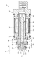
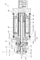
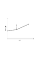
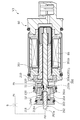
- FIG. 5 is a cross-sectional view showing a state in which the CS valve is closed in the energized state (during normal control) of the capacitance control valve of the first embodiment. It is a graph which shows the change characteristic of the opening area of a CS valve according to the discharge pressure Pd in the energized state (normal control) of the capacity control valve of Example 1, especially when the current is constant. It is sectional drawing which shows the modification of the capacity control valve of Example 1. FIG. It is sectional drawing which shows the state that the CS valve was opened in the non-energized state of the capacity control valve of Example 2 which concerns on this invention.
- FIG. 5 is a cross-sectional view showing a state in which the CS valve is closed in the energized state (during normal control) of the capacitance control valve of the second embodiment. It is a graph which shows the change characteristic of the opening area of a CS valve according to the discharge pressure Pd in the energized state (normal control) of the capacity control valve of Example 2, especially when the current is constant. It is sectional drawing which shows the modification of the capacity control valve of Example 2. FIG. It is sectional drawing which shows the state that the CS valve was opened in the non-energized state of the capacity control valve of Example 3 which concerns on this invention.
- FIG. 5 is a cross-sectional view showing a state in which the CS valve is closed in the energized state (during normal control) of the capacitance control valve of the second embodiment. It is a graph which shows the change characteristic of the opening area of a CS valve according to the discharge pressure Pd in the energized state (normal control) of the capacity control valve of Example 2, especially when the current is
- FIG. 5 is a cross-sectional view showing a state in which the CS valve is closed in the energized state (during normal control) of the capacitance control valve of the third embodiment. It is a graph which shows the change characteristic of the opening area of a CS valve according to the discharge pressure Pd in the energized state (normal control) of the capacity control valve of Example 3, especially when the current is constant. It is sectional drawing which shows the modification of the capacity control valve of Example 3. FIG. It is sectional drawing which shows the state that the CS valve was opened in the non-energized state of the capacity control valve of Example 4 which concerns on this invention.
- FIG. 5 is a cross-sectional view showing a state in which the CS valve is closed in the energized state (during normal control) of the capacitance control valve of the fourth embodiment. It is a graph which shows the change characteristic of the opening area of a CS valve according to the discharge pressure Pd in the energized state (in the case of normal control) of the capacity control valve of Example 4, especially when the current is constant.
- the capacity control valve according to the first embodiment will be described with reference to FIGS. 1 to 3.
- the left and right sides when viewed from the front side of FIG. 1 will be described as the left and right sides of the capacitance control valve.
- the capacity control valve V1 of the present invention is incorporated in a variable capacity compressor (not shown) used in an air conditioning system of an automobile or the like, and variably controls the pressure of a working fluid (hereinafter, simply referred to as “fluid”) as a refrigerant. By doing so, the discharge amount of the variable displacement compressor is controlled and the air conditioning system is adjusted to reach the target cooling capacity.
- a working fluid hereinafter, simply referred to as “fluid”
- variable capacity compressor has a casing including a discharge chamber, a suction chamber, a control chamber, and a plurality of cylinders.
- the variable capacity compressor is provided with a communication passage that directly connects the discharge chamber and the control chamber, and the fixed orifice 9 for balancing the pressure between the discharge chamber and the control chamber is provided in this communication passage. Is provided (see FIGS. 1 and 2).
- variable-capacity compressor includes a rotating shaft that is rotationally driven by an engine (not shown) installed outside the casing, and a swash plate that is eccentrically connected to the rotating shaft by a hinge mechanism in the control chamber.
- Suction pressure Ps in a suction chamber that sucks fluid using a capacitance control valve V1 that is connected to a plate and fitted to reciprocately in each cylinder, and is driven to open and close by electromagnetic force.
- the tilt angle of the swash plate is adjusted by appropriately controlling the pressure in the control chamber while using the discharge pressure Pd of the discharge chamber that discharges the fluid pressurized by the piston and the control pressure Pc of the control chamber that houses the swash plate. By continuously changing the stroke amount of the piston, the discharge amount of the fluid is controlled.
- the capacitance control valve V1 incorporated in the variable capacitance compressor adjusts the current applied to the coil 86 constituting the solenoid 80, and opens and closes the CS valve 50 in the capacitance control valve V1.
- the control pressure Pc in the control chamber is variably controlled by controlling the fluid flowing out from the control chamber to the suction chamber.
- the discharge fluid of the discharge pressure Pd in the discharge chamber is constantly supplied to the control chamber via the fixed orifice 9, and the control pressure Pc in the control chamber can be increased by closing the CS valve 50 in the capacitance control valve V1. It has become like.
- the CS valve 50 is composed of a CS valve body 51 as a valve body and a CS valve seat 10a formed on the inner peripheral surface of the valve housing 10, and has a large diameter portion of the CS valve body 51.
- the CS valve 50 opens and closes when the step portion 51a formed at the left end portion in the axial direction of the 51b is brought into contact with and separated from the CS valve seat 10a.
- the capacity control valve V1 includes a valve housing 10 formed of a metal material or a resin material, a CS valve body 51 in which an axial left end portion is arranged in the valve housing 10, and a CS valve body 51. It is mainly composed of a solenoid 80 which is connected to the valve housing 10 and exerts a driving force on the CS valve body 51.
- the solenoid 80 is inserted into the casing 81 having an opening 81a that opens to the left in the axial direction and the opening 81a of the casing 81 from the left in the axial direction.
- It is mainly composed of a coil spring 85 as a spring urging to the right in a certain axial direction, and an exciting coil 86 wound around the outside of the center post 82 via a bobbin.
- the CS valve body 51 has a large-diameter portion 51b in which a step portion 51a is formed at the left end in the axial direction and a large-diameter portion 51b connected to the left side in the axial direction of the large-diameter portion 51b. It is a stepped columnar body integrally formed with a small diameter portion 51c formed to have a smaller diameter, and also serves as a rod that is arranged through the coil 86 of the solenoid 80. Since the small diameter portion 51c has a constricted portion 51e having a diameter smaller than the axial left end of the small diameter portion 51c at a portion connected to the step portion 51a of the large diameter portion 51b, the CS valve 50 is opened. A flow path with a constant cross section is secured at the time of valve.
- the valve housing 10 has a Ps port 11 as a suction port communicating with the suction chamber of the variable capacity compressor and a control port communicating with the control chamber of the variable capacity compressor.
- Pc port 12 is formed.
- the first axially reciprocatingly arranged first portion of the large diameter portion 51b of the CS valve body 51 which is communicated with the Ps port 11 on the right side in the axial direction, that is, on the solenoid 80 side, is reciprocally arranged in the axial direction.
- a valve chamber 20 is formed, and a second valve chamber 30 is formed on the left side in the axial direction, which is communicated with the Pc port 12 and has a small diameter portion 51c of the CS valve body 51 reciprocally arranged in the axial direction.
- valve hole 10b is formed in which the first valve chamber 20 and the second valve chamber 30 are communicated with each other and the small diameter portion 51c of the CS valve body 51 is inserted. Further, on the inner peripheral surface of the valve housing 10, a CS valve seat 10a is formed at the opening end edge of the valve hole 10b on the first valve chamber 20 side.
- the outer peripheral surface of the small diameter portion 51c of the CS valve body 51 can slide on the left side in the axial direction of the second valve chamber 30, that is, on the opposite side in the axial direction from the solenoid 80 in a substantially sealed state.
- Guide hole 10c is formed.
- a minute gap is formed between the inner peripheral surface of the guide hole 10c and the outer peripheral surface of the small diameter portion 51c of the CS valve body 51 by slightly separating them in the radial direction. It can move smoothly relative to the valve housing 10 in the axial direction.
- the small diameter portion 51c of the CS valve body 51 protrudes to the left in the axial direction from the guide hole 10c of the valve housing 10, and a capacitance is provided at the left end of the CS valve body 51 in the axial direction, that is, the left end of the small diameter portion 51c in the axial direction.
- a pressure receiving surface 51d is formed as a pressure receiving portion for receiving the discharge pressure Pd in the discharge chamber of the variable compressor.
- the non-energized state of the capacitance control valve V1 will be described.
- the movable iron core 84 is pressed to the right in the axial direction by the urging force of the coil spring 85, so that the CS valve body 51 is axially right.
- the step portion 51a of the CS valve body 51 is separated from the CS valve seat 10a, and the CS valve 50 is opened.
- the CS valve body 51 has a pressure receiving surface B having an urging force (F sp ) of the coil spring 85 and a pressure receiving area B equal to the cross-sectional area of the small diameter portion 51c of the CS valve body 51 toward the right in the axial direction.
- the force due to the discharge pressure Pd of the discharge fluid with respect to 51d ( FPd ) and the force due to the control pressure Pc of the control fluid with respect to the CS valve body 51 ( FPc ) act to suck the CS valve body 51 toward the left in the axial direction.
- the force ( FPs ) due to the suction pressure Ps of the fluid is acting.
- the force F rod F sp + F Pd + F Pc ⁇ F Ps acts on the CS valve body 51 with the rightward direction as positive.
- the CS valve body 51 acts on the CS valve body 51 by making the valve port area A where the step portion 51a of the CS valve body 51 and the CS valve seat 10a come into contact with each other and the pressure receiving area B of the CS valve body 51 substantially the same. The influence of the control pressure Pc can be canceled.
- the energized state of the capacitance control valve V1 will be described.
- the electromagnetic force (F sol ) generated by applying a current to the solenoid 80 in the energized state that is, in the normal control, so-called duty control
- the force Frod is the force Frod.
- the movable iron core 84 is pulled toward the left side in the axial direction, that is, toward the center post 82, and the CS valve body 51 fixed to the movable iron core 84 moves together to the left in the axial direction.
- the step portion 51a of the CS valve body 51 is seated on the CS valve seat 10a, and the CS valve 50 is closed.
- an electromagnetic force acts on the CS valve body 51 to the left in the axial direction, and a force F rod acts on the right in the axial direction. That is, with the rightward direction as positive, a force F rod ⁇ F sol , specifically, a force F sp + F Pd + F Pc ⁇ F Ps ⁇ F sol acts on the CS valve body 51.
- the discharge pressure Pd acting on the pressure receiving surface 51d of the CS valve body 51 changes at any time according to the discharge amount of the capacity-variable compressor required from the air conditioning system. Therefore, the force F Pd acting on the CS valve body 51 to the right in the axial direction changes according to the discharge pressure Pd, and when the current applied to the solenoid 80 is constant, the solid line graph in FIG. As shown, the opening area of the CS valve 50 increases proportionally according to the discharge pressure Pd. As shown by the dotted line graph in FIG. 3, if the discharge pressure Pd is not applied to the pressure receiving surface 51d of the CS valve body 51, the opening of the CS valve 50 when the current I energized to the solenoid 80 is constant. The area does not change (the same applies to the dotted graphs in FIGS. 7, 11 and 15 described later).
- the capacitance control valve V1 opens and closes the CS valve 50 and supplies the control fluid of the control pressure Pc supplied from the Pc port 12 to the suction chamber via the Ps port 11 to supply the control pressure Pc in the control chamber.
- Pc-Ps control is performed, and the discharge pressure Pd, which has a higher pressure than the control pressure Pc and the suction pressure Ps, is applied to the right side of the pressure receiving surface 51d of the CS valve body 51, that is, the CS valve 50. It can be used to correct the operation of the CS valve body 51 by acting in the valve opening direction. Therefore, it becomes easy to adjust the valve opening degree of the CS valve 50, and the control pressure Pc of the air conditioning system can be reached to the target value in a short time.
- the pressure receiving surface 51d on which the discharge pressure Pd acts on the CS valve body 51 a force corresponding to the discharge pressure Pd is applied to the CS valve body 51 having the step portion 51a for opening and closing the CS valve 50. Since FPd ) can be applied, the response to the correction of the operation of the CS valve body 51 is high.
- the control pressure Pc of the air conditioning system can be reached to the target value in a shorter time.
- the capacitance control valve V1 is configured as a normally open type in which the CS valve body 51 is urged by the coil spring 85 in the valve opening direction of the CS valve 50, the current value of the current applied to the solenoid 80 decreases.
- the CS valve body 51 can be reliably moved to the valve opening position, and the maximum duty can be instantly returned from the maximum energized state to a less energized state, that is, so-called duty control. Further, by moving the CS valve body 51 in the valve opening direction in the non-energized state of the capacitance control valve V1, the control pressure Pc and the suction pressure Ps can be easily matched.
- a guide hole 10c and a CS valve are provided on the side opposite to the solenoid 80 in the axial direction, that is, at the left end in the axial direction of the valve housing 10.
- An O-ring 113 may be provided as a sealing portion for sealing between the small diameter portion 51c of the body 51. According to this, the discharge fluid of the discharge pressure Pd acting on the pressure receiving surface 51d of the CS valve body 51 is prevented from entering the valve housing 10 through the guide hole 10c, so that the controllability of the control pressure Pc is improved. Can be done.
- the O-ring 113 is substantially fixed by a fixing member 114 provided at the left end in the axial direction of the valve housing 10, so that the sealing property can be maintained regardless of the operation of the CS valve body 51.
- the capacity control valve according to the second embodiment will be described with reference to FIGS. 5 to 7. The description of the same configuration as that of the first embodiment and the overlapping configuration will be omitted.
- the CS valve body 251 as a valve body has a large diameter portion 251b in which a step portion 251a is formed at the left end in the axial direction. It is a stepped columnar body that is integrally formed with a small diameter portion 251c that is connected to the left side of the diameter portion 251b in the axial direction and is formed to have a diameter smaller than that of the large diameter portion 251b, and penetrates the coil 86 of the solenoid 80. It also serves as the rod to be placed.
- the CS valve 250 Since the small diameter portion 251c has a constricted portion 251e having a diameter smaller than the axial left end of the small diameter portion 251c at a portion connected to the step portion 251a of the large diameter portion 251b, the CS valve 250 is opened. A flow path with a constant cross section is secured at the time of valve.
- the first valve housing 210 and the second valve housing 211 inserted into the first valve housing 210 are mainly configured as the valve housing.
- the first valve housing 210 is formed with a Ps port 11 as a suction port that communicates with the suction chamber of the variable capacity compressor.
- the second valve housing 211 is formed with a Pc port 12 as a control port that communicates with the control chamber of the variable capacity compressor.
- the first valve housing 210 is formed with a recess 210e in which the inner diameter side of the left end in the axial direction is recessed to the right in the axial direction, and the right end portion in the axial direction of the second valve housing 211 is inserted from the left side in the axial direction. It is connected and fixed in a substantially sealed state.
- a first valve chamber 220 is formed which is communicated with the Ps port 11 and in which the left end portion in the axial direction of the large diameter portion 251b of the CS valve body 251 is reciprocally arranged in the axial direction.
- a second valve chamber 230 is formed which is communicated with the Pc port 12 and in which the small diameter portion 251c of the CS valve body 251 is reciprocally arranged in the axial direction.
- a valve hole 210b is formed in which the first valve chamber 220 and the second valve chamber 230 are communicated with each other and the small diameter portion 251c of the CS valve body 251 is inserted. Further, on the inner peripheral surface of the first valve housing 210, a CS valve seat 210a is formed at the opening end edge of the valve hole 210b on the first valve chamber 220 side. Further, on the inner peripheral surface of the first valve housing 210, the outer peripheral surface of the large diameter portion 251b of the CS valve body 251 can slide on the solenoid 80 side of the CS valve seat 210a and the first valve chamber 220 in a substantially sealed state. Guide hole 210f is formed.
- a minute gap is formed between the inner peripheral surface of the guide hole 210f and the outer peripheral surface of the large diameter portion 251b of the CS valve body 251 by slightly separating them in the radial direction, and the CS valve body 251 has a small gap. , It is possible to move smoothly relative to the first valve housing 210 in the axial direction.
- a separate sliding rod that is axially separated from the CS valve body 251 on the left side in the axial direction of the second valve chamber 230, that is, on the opposite side in the axial direction of the solenoid 80.
- a guide hole 211a is formed so that the outer peripheral surface of the 252 can slide in a substantially sealed state.
- a minute gap is formed between the inner peripheral surface of the guide hole 211a and the outer peripheral surface of the sliding rod 252 by slightly separating them in the radial direction, and the sliding rod 252 is the second valve housing. It is possible to move smoothly in the axial direction with respect to 211. Further, the sliding rod 252 is arranged at a coaxial position with the CS valve body 251.
- the left end of the sliding rod 252 protrudes to the left in the axial direction from the guide hole 211a of the second valve housing 211, and the discharge pressure Pd of the discharge chamber of the variable displacement compressor is applied to the left end in the axial direction.
- a pressure receiving surface 252a is formed as a pressure receiving portion for receiving pressure.
- a support cap 254 is inserted from the right side in the axial direction into the right end portion in the axial direction arranged in the second valve chamber 230 of the sliding rod 252.
- a coil spring 253 as an urging means is interposed between the sliding rod 252 and the CS valve body 251.
- the coil spring 253 is arranged in the second valve chamber 230, and the axial left end of the coil spring 253 is on the axial right end surface of the flange portion 254a extending from the axial left end of the support cap 254 to the outer diameter side.
- the coil spring 253 is held in contact with the right end in the axial direction in contact with the left end surface in the axial direction of the support plate 255 fitted to the small diameter portion 251c of the CS valve body 251. That is, the sliding rod 252 and the CS valve body 251 are in a state in which the axial ends facing each other are connected to each other so as to be in contact with each other via the coil spring 253.
- the discharge pressure Pd of the discharge fluid acting on the pressure receiving surface 252a having the pressure receiving area B equal to the cross-sectional area of the sliding rod 252 changes at any time according to the discharge amount of the capacitance variable compressor required from the air conditioning system. doing. Therefore, the force F Pd acting on the CS valve body 251 in the axial direction changes according to the discharge pressure Pd, and when the current I energized in the solenoid 80 is constant, the solid line graph in FIG. As shown by, the force F Pd acting from the sliding rod 252 to the right side in the axial direction with respect to the CS valve body 251 via the coil spring 253 changes according to the discharge pressure Pd.
- the sliding rod 252 is pressed to the left in the axial direction by the urging force of the coil spring 253 to be inserted into the sliding rod 252.
- the left end of the flange portion 254a of the support cap 254 in the axial direction is in contact with the inner surface of the second valve chamber 230 of the second valve housing 211.
- the coil Since the urging force of the spring 253 becomes the resistance of the force that moves the sliding rod 252 to the right in the axial direction due to the increase in the discharge pressure Pd, it becomes difficult for the force corresponding to the discharge pressure Pd to act on the CS valve body 251. ing. Further, after the inflection point C in FIG. 7, the compression width of the coil spring 253 does not change by maintaining the state in which the right end in the axial direction of the support cap 254 is in contact with the left end in the axial direction of the CS valve body 251. Since the urging force of the coil spring 253 becomes constant with respect to the increase in the force corresponding to the discharge pressure Pd, the force corresponding to the discharge pressure Pd is likely to act on the CS valve body 251.
- the operation of the CS valve body 251 can be corrected. It is easy to change the control characteristics by correction using the discharge pressure Pd as appropriate.
- the control characteristics by correction may be appropriately changed by changing the separation distance between the sliding rod 252 and the CS valve body 251 and the spring constant of the coil spring 253.
- valve opening area A where the step portion 251a of the CS valve body 251 and the CS valve seat 210a come into contact with each other and the pressure receiving area B of the sliding rod 252 substantially the same it acts on the CS valve body 251.
- the influence of the control pressure Pc to be applied can be canceled.
- the valve port area A and the pressure receiving area B can be freely set.
- a guide hole 211a is provided on the side opposite to the solenoid 80 in the axial direction, that is, at the left end portion in the axial direction of the second valve housing 211.
- An O-ring 213 may be provided as a sealing portion for sealing between the sliding rod 252 and the sliding rod 252. According to this, the discharge fluid of the discharge pressure Pd acting on the pressure receiving surface 252a of the sliding rod 252 is prevented from entering the first valve housing 210 and the second valve housing 211 through the guide hole 211a. The controllability of the pressure Pc can be improved.
- the O-ring 213 is substantially fixed by a fixing member 214 provided at the left end in the axial direction of the second valve housing 211, so that the sealing property can be maintained regardless of the operation of the sliding rod 252.
- the capacity control valve according to the third embodiment will be described with reference to FIGS. 9 to 11. It should be noted that the description of the same configuration as that of the second embodiment and the overlapping configuration will be omitted.
- the CS valve body 351 as a valve body has a large diameter portion 351b in which a step portion 351a is formed at the left end in the axial direction. It is a stepped columnar body that is integrally formed with a small diameter portion 351c that is connected to the left side of the diameter portion 351b in the axial direction and is formed to have a diameter smaller than that of the large diameter portion 351b, and penetrates the coil 86 of the solenoid 80. It also serves as the rod to be placed.
- a flow path having a constant cross section is secured when the CS valve 350 is opened.
- a coil spring 353 as an urging means is interposed between the CS valve body 351 and the separate sliding rod 252 which is separated from the CS valve body 351 in the axial direction and the left end in the axial direction of the first valve housing 210.
- the coil spring 353 is arranged in the second valve chamber 230, and the axial left end of the coil spring 353 abuts on the axial right end surface of the flange portion 254a formed on the support cap 254, and the coil spring 353 The right end in the axial direction is held in contact with the left end surface in the axial direction of the first valve housing 210. That is, the sliding rod 252 and the CS valve body 351 are arranged so that their axial ends facing each other can be brought into contact with each other.
- the area where the operation of the CS valve body 351 is corrected and the area where the operation is not corrected are not corrected. Since it is possible to set and, it is easy to appropriately change the control characteristics by the correction using the discharge pressure Pd.
- the control characteristics by correction may be appropriately changed by changing the separation distance between the sliding rod 252 and the CS valve body 351 and the spring constant of the coil spring 353.
- the guide hole 211a and the sliding rod 252 provided on the side opposite to the solenoid 80 in the axial direction, that is, the second valve housing 211.
- An O-ring 313 may be provided as a sealing portion for sealing between the two. According to this, the discharge fluid of the discharge pressure Pd acting on the pressure receiving surface 252a of the sliding rod 252 is prevented from entering the first valve housing 210 and the second valve housing 211 through the guide hole 211a. The controllability of the pressure Pc can be improved.
- the O-ring 313 is substantially fixed by a fixing member 314 provided at the left end in the axial direction of the second valve housing 211, so that the sealing property can be maintained regardless of the operation of the sliding rod 252.
- the capacity control valve according to the fourth embodiment will be described with reference to FIGS. 13 to 15. The description of the same configuration as that of the first embodiment and the overlapping configuration will be omitted.
- the CS valve body 451 as a valve body is an integral columnar body having a substantially constant cross section, with respect to the coil 86 of the solenoid 80. It also serves as a rod that is arranged through. Further, at the right end of the CS valve body 451 in the axial direction, a pressure receiving surface 451b is formed as a pressure receiving portion for receiving the discharge pressure Pd in the discharge chamber of the variable capacitance compressor.
- the valve housing 410 includes a Ps port 11 as a suction port communicating with the suction chamber of the variable capacity compressor, a Pc port 12 as a control port communicating with the control chamber of the variable capacity compressor, and a variable capacity compressor.
- a Pd port 13 that communicates with the discharge chamber of the machine is formed.
- a first valve chamber 420 is formed on the left side in the axial direction in which the left end portion in the axial direction of the CS valve body 451 is reciprocally arranged in the axial direction, and the Ps port 11 is the valve housing.
- the Pc port 12 extends from the outer peripheral surface of the 410 in the inner diameter direction and communicates with the first valve chamber 420, and the Pc port 12 extends axially to the right from the inner diameter side of the left end of the valve housing 410 in the axial direction and communicates with the first valve chamber 420.
- a second valve chamber 430 that communicates with the Pd port 13 is formed on the right side in the axial direction, that is, on the solenoid 80 side.
- 410b is formed.
- a CS valve seat 410a is formed at the opening end edge of the Pc port 12 on the first valve chamber 420 side.
- a minute gap is formed between the inner peripheral surface of the guide hole 410b and the outer peripheral surface of the CS valve body 451 by slightly separating them in the radial direction, and the CS valve body 451 is formed in the valve housing 410. On the other hand, it can move smoothly in the axial direction.
- first valve chamber 420 and the second valve chamber 430 are sealed in a substantially sealed state by a clearance seal as a sealing portion formed by the inner peripheral surface of the guide hole 410b and the outer peripheral surface of the CS valve body 451. Therefore, the discharge fluid of the discharge pressure Pd supplied from the Pd port 13 to the second valve chamber 430 is prevented from entering the first valve chamber 420. Further, the discharge fluid of the discharge pressure Pd supplied from the Pd port 13 to the second valve chamber 430 reaches the inner peripheral surface of the insertion hole 82a extending in the axial direction in the center post 82 constituting the solenoid 80 and the insertion hole 82a.
- the non-energized state of the capacitance control valve V4 will be described.
- the capacity control valve V4 when the movable iron core 84 is pressed to the right in the axial direction by the urging force of the coil spring 85 in the non-energized state, the CS valve body 451 is pushed to the right in the axial direction.
- the left end 451a of the CS valve body 451 in the axial direction is separated from the CS valve seat 410a, and the CS valve 450 is opened.
- the urging force (F sp ) of the coil spring 85 and the force ( FP c ) due to the control pressure Pc of the control fluid with respect to the CS valve body 451 act on the CS valve body 451 toward the right in the axial direction.
- the control valve V4 is energized, i.e. the normal control, during the so-called duty control, the electromagnetic force generated by the current is applied to the solenoid 80 (F sol) force F.
- Rod F sol > F rod
- the movable iron core 84 is pulled toward the left side in the axial direction, that is, toward the center post 82, and the CS valve body 451 fixed to the movable iron core 84 moves together to the left in the axial direction.
- the axial left end 451a of the CS valve body 451 is seated on the CS valve seat 410a, and the CS valve 450 is closed.
- an electromagnetic force acts on the CS valve body 451 to the left in the axial direction, and a force Frod acts on the right in the axial direction. That is, the force F rod- F sol , specifically, the force F sp + F Pc- F Pd- F sol , acts on the CS valve body 451 with the rightward direction as positive.
- the discharge pressure Pd acting on the pressure receiving surface 451b of the CS valve body 451 changes at any time according to the discharge amount of the capacity variable compressor required from the air conditioning system. Therefore, the force F Pd acting on the CS valve body 451 in the axial direction changes according to the discharge pressure Pd, and when the current I energized in the solenoid 80 is constant, the solid line graph in FIG. As shown by, the opening area of the CS valve 450 is proportionally reduced according to the discharge pressure Pd.
- the capacitance control valve V4 opens and closes the CS valve 450 and supplies the control fluid of the control pressure Pc supplied from the Pc port 12 to the suction chamber via the Ps port 11 to supply the control pressure Pc in the control chamber.
- Pc-Ps control is performed to reduce the pressure, and the discharge pressure Pd supplied from the Pd port 13 and having a higher pressure than the control pressure Pc and the suction pressure Ps is axially left with respect to the pressure receiving surface 451b of the CS valve body 451. It can be used to correct the operation of the CS valve body 451 by acting in the closing direction of the CS valve 450. Therefore, it becomes easy to adjust the valve opening degree of the CS valve 450, and the control pressure Pc of the air conditioning system can be reached to the target value in a short time.
- the sealing property of the clearance seal may be improved by the labyrinth effect of the groove.
- the CS valve body has been described as also serving as a rod that is arranged through the coil 86 of the solenoid 80, but the present invention is not limited to this, and the CS valve body reciprocates in both axial directions with a separate rod. It may be configured to be flexible.
- the capacitance control valves V1 to V4 have been described as being configured as a normally open type in which the CS valve body is urged in the valve opening direction of the CS valve by the coil spring 85, but the present invention is not limited to this.
- the CS valve body may be configured as a normally closed type in which the coil spring 85 is urged in the valve closing direction of the CS valve.
- the configuration in which the Pc port 12 is formed on the left side in the axial direction with respect to the Ps port 11 has been described, but the Pc port 12 is arranged so as to be formed on the right side in the axial direction with respect to the Ps port 11. May be replaced.
- the shapes and arrangements of the CS valve body and the CS valve seat shall be changed as appropriate.
- the left end portion in the axial direction of the CS valve body or the sliding rod on which the pressure receiving surface is formed protrudes to the left in the axial direction from the guide hole, but the present invention is limited to this. Instead, the left end of the CS valve body or the sliding rod in the axial direction, that is, the pressure receiving surface may be always arranged inside the guide hole.
- the present invention is not limited to this.
- the seal portion may be freely configured as long as it can prevent the discharge fluid of the discharge pressure Pd acting on the surface from entering the valve housing.
- the sliding rod 252 and the CS valve body 251 may not be in contact with each other and may be always separated in the axial direction.
- the coil spring 353 is not limited to the one interposed between the sliding rod 252 and the left end in the axial direction of the first valve housing 210, and the right end in the axial direction of the coil spring 353 is, for example, the first. 2 It may be in contact with the inward flange portion formed on the inner peripheral surface of the valve housing 211.
- the pressure receiving portion is not limited to the one formed on the axial end face of the CS valve body or the sliding rod.
- the pressure receiving portion is not limited to the one formed on the axial end face of the CS valve body or the sliding rod.
- the pressure receiving portion is not limited to the one formed on the axial end face of the CS valve body or the sliding rod.
Landscapes
- Engineering & Computer Science (AREA)
- General Engineering & Computer Science (AREA)
- Mechanical Engineering (AREA)
- Physics & Mathematics (AREA)
- Electromagnetism (AREA)
- Compressors, Vaccum Pumps And Other Relevant Systems (AREA)
- Magnetically Actuated Valves (AREA)
Abstract
Description
吸入圧力の吸入流体が通過する吸入ポートおよび制御圧力の制御流体が通過する制御ポートが形成されたバルブハウジングと、
ソレノイドにより駆動される弁体と、
前記弁体を前記ソレノイドによる駆動方向と反対方向に付勢するスプリングと、
CS弁座と前記弁体とにより構成され前記弁体の移動により前記制御ポートと前記吸入ポートとの連通を開閉するCS弁と、を備え、
前記CS弁の開閉により制御圧力の制御を行い、
吐出圧力に応じた力を前記弁体の軸方向に作用させる受圧部を有している。
これによれば、圧力の高い吐出圧力により弁体の動作を補正することができる。そのため、CS弁の弁開度の調整を行いやすくなり空調システムの制御圧力を目標の値までより短時間で到達させることができる。
これによれば、ソレノイドの電磁力により動作する弁体に吐出圧力に応じた力を作用させることができるため、弁体の動作の補正に対する応答性が高い。
これによれば、ソレノイドにより駆動される弁体の動作と、吐出圧力に応じた力が軸方向に作用することによる摺動ロッドの動作とを組み合わせることにより、弁体の動作を補正する領域と補正しない領域とを設定することができるため、補正による制御特性を適宜変更しやすい。
これによれば、摺動ロッドが弁体と接するまでの領域を、弁体の動作に吐出圧力に応じた力が作用しない緩衝領域として設定することができる。
これによれば、摺動ロッドに作用する吐出圧力に応じた力が付勢手段を介して弁体に作用するため、摺動ロッドが弁体と接するまでの領域を、弁体の動作に吐出圧力に応じた力が作用し難い緩衝領域として設定することができる。
これによれば、摺動ロッドが弁体と接するまでの領域を、弁体の動作に吐出圧力に応じた力が作用しない緩衝領域として設定することができ、かつ摺動ロッドが弁体と接することにより、摺動ロッドに作用する吐出圧力に応じた力を付勢手段の付勢力により抑制した状態で弁体に作用させることができる。
これによれば、弁体の受圧部に作用する吐出圧力の吐出流体がバルブハウジング内に侵入しないようにシールされるため、吐出圧力が制御圧力や吸入圧力に直接影響を与え難い。
これによれば、摺動ロッドの受圧部に作用する吐出圧力の吐出流体がバルブハウジング内に侵入しないようにシールされるため、吐出圧力が制御圧力や吸入圧力に直接影響を与え難い。
これによれば、非通電時において弁体を開弁方向に移動させることにより制御圧力と吸入圧力を一致させやすく、かつ最大通電状態から通常制御に瞬時に復帰させることができる。
10 バルブハウジング
10a CS弁座
10c ガイド孔
11 Psポート(吸入ポート)
12 Pcポート(制御ポート)
13 Pdポート
20 第1弁室
30 第2弁室
50 CS弁
51 CS弁体(弁体)
51a 段部
51d 受圧面(受圧部)
80 ソレノイド
85 コイルスプリング(スプリング)
113 Oリング(シール部)
210 第1バルブハウジング(バルブハウジング)
210a CS弁座
211 第2バルブハウジング(バルブハウジング)
211a ガイド孔
213 Oリング(シール部)
250 CS弁
251 CS弁体(弁体)
251a 段部
252 摺動ロッド
252a 受圧面(受圧部)
253 コイルスプリング(付勢手段)
254 支持キャップ
255 支持プレート
313 Oリング(シール部)
350 CS弁
351 CS弁体(弁体)
351a 段部
353 コイルスプリング(付勢手段)
410 バルブハウジング
410a CS弁座
410b ガイド孔
450 CS弁
451 CS弁体(弁体)
451b 受圧面(受圧部)
Pc 制御圧力
Pd 吐出圧力
Ps 吸入圧力
V1~V4 容量制御弁
Claims (9)
- 吸入圧力の吸入流体が通過する吸入ポートおよび制御圧力の制御流体が通過する制御ポートが形成されたバルブハウジングと、
ソレノイドにより駆動される弁体と、
前記弁体を前記ソレノイドによる駆動方向と反対方向に付勢するスプリングと、
CS弁座と前記弁体とにより構成され前記弁体の移動により前記制御ポートと前記吸入ポートとの連通を開閉するCS弁と、を備え、
前記CS弁の開閉により制御圧力の制御を行い、
吐出圧力に応じた力を前記弁体の軸方向に作用させる受圧部を有している容量制御弁。 - 前記受圧部は、前記弁体に設けられている請求項1に記載の容量制御弁。
- 前記受圧部は、前記弁体と対向して離間する別体の摺動ロッドに設けられている請求項1に記載の容量制御弁。
- 前記摺動ロッドは、前記弁体と接離可能に離間している請求項3に記載の容量制御弁。
- 前記摺動ロッドと前記弁体との間には、付勢手段が介在している請求項3または4に記載の容量制御弁。
- 前記摺動ロッドと前記バルブハウジングとの間には、付勢手段が介在している請求項4に記載の容量制御弁。
- 前記ソレノイドと軸方向反対側において前記バルブハウジングに設けられるガイド孔と前記弁体との間をシールするシール部が設けられている請求項2に記載の容量制御弁。
- 前記ソレノイドと軸方向反対側において前記バルブハウジングに設けられるガイド孔と前記摺動ロッドとの間をシールするシール部が設けられている請求項3ないし6のいずれかに記載の容量制御弁。
- 前記弁体は、前記スプリングにより前記CS弁の開弁方向に付勢されている請求項1ないし8のいずれかに記載の容量制御弁。
Priority Applications (8)
| Application Number | Priority Date | Filing Date | Title |
|---|---|---|---|
| EP20795023.9A EP3961075A4 (en) | 2019-04-24 | 2020-04-21 | CAPACITY CONTROL VALVE |
| KR1020217036305A KR102568391B1 (ko) | 2019-04-24 | 2020-04-21 | 용량 제어 밸브 |
| EP23180732.2A EP4242504B1 (en) | 2019-04-24 | 2020-04-21 | Capacity control valve |
| KR1020237023765A KR102634942B1 (ko) | 2019-04-24 | 2020-04-21 | 용량 제어 밸브 |
| CN202080028782.3A CN113692510B (zh) | 2019-04-24 | 2020-04-21 | 容量控制阀 |
| JP2021516129A JP7451064B2 (ja) | 2019-04-24 | 2020-04-21 | 容量制御弁 |
| US17/603,284 US11988296B2 (en) | 2019-04-24 | 2020-04-21 | Capacity control valve |
| US18/225,085 US12140243B2 (en) | 2019-04-24 | 2023-07-21 | Capacity control valve |
Applications Claiming Priority (2)
| Application Number | Priority Date | Filing Date | Title |
|---|---|---|---|
| JP2019-083385 | 2019-04-24 | ||
| JP2019083385 | 2019-04-24 |
Related Child Applications (2)
| Application Number | Title | Priority Date | Filing Date |
|---|---|---|---|
| US17/603,284 A-371-Of-International US11988296B2 (en) | 2019-04-24 | 2020-04-21 | Capacity control valve |
| US18/225,085 Division US12140243B2 (en) | 2019-04-24 | 2023-07-21 | Capacity control valve |
Publications (1)
| Publication Number | Publication Date |
|---|---|
| WO2020218285A1 true WO2020218285A1 (ja) | 2020-10-29 |
Family
ID=72941935
Family Applications (1)
| Application Number | Title | Priority Date | Filing Date |
|---|---|---|---|
| PCT/JP2020/017169 Ceased WO2020218285A1 (ja) | 2019-04-24 | 2020-04-21 | 容量制御弁 |
Country Status (6)
| Country | Link |
|---|---|
| US (2) | US11988296B2 (ja) |
| EP (2) | EP4242504B1 (ja) |
| JP (1) | JP7451064B2 (ja) |
| KR (2) | KR102568391B1 (ja) |
| CN (1) | CN113692510B (ja) |
| WO (1) | WO2020218285A1 (ja) |
Families Citing this family (2)
| Publication number | Priority date | Publication date | Assignee | Title |
|---|---|---|---|---|
| JP7350458B2 (ja) * | 2019-07-11 | 2023-09-26 | イーグル工業株式会社 | 容量制御弁 |
| CN115405710B (zh) * | 2022-09-01 | 2023-06-09 | 唐山传奇科技有限公司 | 自闭式高速泄压阀 |
Citations (4)
| Publication number | Priority date | Publication date | Assignee | Title |
|---|---|---|---|---|
| JP2003322086A (ja) * | 2002-02-04 | 2003-11-14 | Eagle Ind Co Ltd | 容量制御弁 |
| JP2014080927A (ja) * | 2012-10-17 | 2014-05-08 | Tgk Co Ltd | 可変容量圧縮機用制御弁 |
| JP2014126025A (ja) * | 2012-12-27 | 2014-07-07 | Tgk Co Ltd | 可変容量圧縮機用制御弁 |
| JP2017031834A (ja) | 2015-07-29 | 2017-02-09 | 株式会社豊田自動織機 | 容量制御弁 |
Family Cites Families (95)
| Publication number | Priority date | Publication date | Assignee | Title |
|---|---|---|---|---|
| GB787961A (en) | 1954-07-14 | 1957-12-18 | William Hector Mashinter | Metering pump |
| US3765644A (en) | 1972-01-19 | 1973-10-16 | Control Concepts | Controlled air gap in a solenoid operated valve |
| JPS581598B2 (ja) | 1978-05-15 | 1983-01-12 | 富士通株式会社 | 表示像補正方式 |
| ES480613A1 (es) | 1978-06-28 | 1979-11-16 | Sibe | Perfeccionamientos en las electrovalvulas. |
| JPS5983539U (ja) | 1982-11-30 | 1984-06-06 | カシオ計算機株式会社 | インクカ−トリツジ |
| JPS62170466A (ja) | 1986-01-23 | 1987-07-27 | Yoshikawa Kogyo Co Ltd | 銅基合金母材への耐熱溶射皮膜形成方法 |
| JPS6316177A (ja) | 1986-07-08 | 1988-01-23 | Sanden Corp | 容量可変型圧縮機 |
| US5022629A (en) | 1988-01-04 | 1991-06-11 | Interface, Inc. | Valve construction |
| DE3934771C1 (ja) | 1989-10-18 | 1991-03-28 | Lucas Industries P.L.C., Birmingham, West Midlands, Gb | |
| US5199855A (en) | 1990-09-27 | 1993-04-06 | Zexel Corporation | Variable capacity compressor having a capacity control system using an electromagnetic valve |
| DE4103365A1 (de) | 1991-02-05 | 1992-08-13 | Teves Metallwaren Alfred | Drucksteuerventil |
| JPH04342883A (ja) * | 1991-05-17 | 1992-11-30 | Sanden Corp | 容量可変型斜板式圧縮機 |
| DE4137123A1 (de) | 1991-11-12 | 1993-05-13 | Teves Gmbh Alfred | Drucksteuerventil |
| JP3242496B2 (ja) | 1993-07-06 | 2001-12-25 | 株式会社豊田自動織機 | 可変容量圧縮機の外部切換式容量制御弁 |
| JPH10318414A (ja) * | 1997-05-20 | 1998-12-04 | Toyota Autom Loom Works Ltd | 電磁式制御弁 |
| JPH11280658A (ja) | 1998-03-25 | 1999-10-15 | Sanden Corp | 可変容量圧縮機の容量制御弁 |
| JP4149558B2 (ja) | 1998-03-27 | 2008-09-10 | サンデン株式会社 | 可変容量圧縮機の容量制御弁 |
| JP3783434B2 (ja) | 1998-04-13 | 2006-06-07 | 株式会社豊田自動織機 | 容量可変型斜板式圧縮機、及び空調用冷房回路 |
| JPH11336660A (ja) | 1998-05-27 | 1999-12-07 | Toyota Autom Loom Works Ltd | 可変容量圧縮機およびその組み付け方法 |
| JP2000064957A (ja) | 1998-08-17 | 2000-03-03 | Toyota Autom Loom Works Ltd | 容量可変型斜板式圧縮機および抜き側制御弁 |
| JP3984724B2 (ja) | 1998-09-10 | 2007-10-03 | 株式会社豊田自動織機 | 容量可変型斜板式圧縮機の制御弁及び斜板式圧縮機 |
| JP3435077B2 (ja) | 1998-09-16 | 2003-08-11 | 株式会社鷺宮製作所 | ベローズ式圧力応動弁 |
| US6038871A (en) * | 1998-11-23 | 2000-03-21 | General Motors Corporation | Dual mode control of a variable displacement refrigerant compressor |
| JP2000161234A (ja) | 1998-11-27 | 2000-06-13 | Toyota Autom Loom Works Ltd | 容量可変型圧縮機及び容量可変型圧縮機の容量制御弁 |
| JP3581598B2 (ja) | 1999-04-21 | 2004-10-27 | 株式会社テージーケー | 容量可変圧縮機の容量制御装置 |
| JP3576866B2 (ja) | 1999-05-10 | 2004-10-13 | 株式会社テージーケー | 車輌用バイパス管路付冷凍サイクル |
| JP4392631B2 (ja) | 1999-06-24 | 2010-01-06 | 株式会社ヴァレオサーマルシステムズ | 冷凍サイクルの可変容量制御装置 |
| JP3991556B2 (ja) | 1999-10-04 | 2007-10-17 | 株式会社豊田自動織機 | 容量可変型圧縮機の制御弁 |
| JP3963619B2 (ja) | 1999-11-05 | 2007-08-22 | 株式会社テージーケー | 冷凍サイクルの圧縮容量制御装置 |
| JP2001153043A (ja) | 1999-12-01 | 2001-06-05 | Sanden Corp | 容量可変型斜板式圧縮機 |
| JP2001165055A (ja) | 1999-12-09 | 2001-06-19 | Toyota Autom Loom Works Ltd | 制御弁及び容量可変型圧縮機 |
| JP2002070732A (ja) | 2000-09-01 | 2002-03-08 | Zexel Valeo Climate Control Corp | 冷凍サイクルの可変容量制御装置 |
| JP2002089442A (ja) | 2000-09-08 | 2002-03-27 | Toyota Industries Corp | 容量可変型圧縮機の制御弁 |
| JP2002201913A (ja) | 2001-01-09 | 2002-07-19 | Mitsubishi Heavy Ind Ltd | ガスタービンの分割壁およびシュラウド |
| JP2002221153A (ja) | 2001-01-23 | 2002-08-09 | Toyota Industries Corp | 容量可変型圧縮機の制御弁 |
| JP3943871B2 (ja) | 2001-07-25 | 2007-07-11 | 株式会社テージーケー | 可変容量圧縮機および可変容量圧縮機用容量制御弁 |
| US8418723B2 (en) | 2001-12-11 | 2013-04-16 | Kayaba Industry Co., Ltd. | Electromagnetic proportional flow rate control valve |
| KR100466951B1 (ko) | 2002-04-01 | 2005-01-24 | 현대모비스 주식회사 | 에이비에스용 솔레노이드 밸브 |
| GB0214467D0 (en) | 2002-06-24 | 2002-08-07 | Delphi Tech Inc | Control valve for air conditioning compressor |
| JP4242624B2 (ja) | 2002-09-26 | 2009-03-25 | イーグル工業株式会社 | 容量制御弁及びその制御方法 |
| JP2004162567A (ja) | 2002-11-12 | 2004-06-10 | Fuji Koki Corp | 可変容量型圧縮機用の制御弁 |
| JP2004162640A (ja) | 2002-11-14 | 2004-06-10 | Toyota Industries Corp | 容量可変型圧縮機の制御弁 |
| JP2004162856A (ja) | 2002-11-15 | 2004-06-10 | Hitachi Unisia Automotive Ltd | 電磁弁構造 |
| DE10321413B4 (de) | 2003-05-13 | 2014-06-26 | Robert Bosch Gmbh | Elektromagnetisch betätigbares Ventil |
| JP2005098197A (ja) | 2003-09-04 | 2005-04-14 | Tgk Co Ltd | 可変容量圧縮機用容量制御弁 |
| JP2005291142A (ja) | 2004-04-02 | 2005-10-20 | Zexel Valeo Climate Control Corp | 可変容量型圧縮機の制御装置及び圧力制御弁 |
| JP2006097665A (ja) * | 2004-06-28 | 2006-04-13 | Toyota Industries Corp | 可変容量型圧縮機における容量制御弁 |
| JP2006017087A (ja) | 2004-07-05 | 2006-01-19 | Calsonic Kansei Corp | 電磁式制御弁および該電磁式制御弁を備えた可変容量圧縮機 |
| JP4431462B2 (ja) | 2004-08-10 | 2010-03-17 | 株式会社鷺宮製作所 | 斜板式容量可変型圧縮機および電磁制御弁 |
| JP4626808B2 (ja) * | 2005-04-26 | 2011-02-09 | 株式会社豊田自動織機 | 可変容量型クラッチレス圧縮機用の容量制御弁 |
| JP2007092829A (ja) | 2005-09-28 | 2007-04-12 | Toyota Motor Corp | 弁 |
| JP2007177627A (ja) | 2005-12-27 | 2007-07-12 | Sanden Corp | 可変容量圧縮機の吐出容量制御弁 |
| DE102006002638A1 (de) | 2006-01-19 | 2007-07-26 | Robert Bosch Gmbh | Magnetventil |
| CN2869383Y (zh) | 2006-02-17 | 2007-02-14 | 苏州新智机电工业有限公司 | 汽车空调变排量压缩机控制阀 |
| FR2901340A1 (fr) | 2006-05-17 | 2007-11-23 | Messier Bugatti Sa | Agencement de distributeur hydraulique sous forme de cartouche |
| JP2008157031A (ja) | 2006-12-20 | 2008-07-10 | Toyota Industries Corp | クラッチレス可変容量型圧縮機における電磁式容量制御弁 |
| US9797519B2 (en) | 2007-01-10 | 2017-10-24 | Fritz Gyger Ag | Micro-valve |
| DE102007053134A1 (de) | 2007-11-08 | 2009-05-14 | Robert Bosch Gmbh | Ventilpatrone für ein Magnetventil und zugehöriges Magnetventil |
| JP5222447B2 (ja) | 2008-06-11 | 2013-06-26 | サンデン株式会社 | 可変容量圧縮機 |
| JP5251762B2 (ja) | 2009-07-08 | 2013-07-31 | アイシン・エィ・ダブリュ株式会社 | ソレノイドバルブ |
| JP5271216B2 (ja) | 2009-09-17 | 2013-08-21 | 日立オートモティブシステムズ株式会社 | ノーマルオープン型電磁弁 |
| JP2011094554A (ja) | 2009-10-30 | 2011-05-12 | Tgk Co Ltd | 可変容量圧縮機 |
| US8757988B2 (en) * | 2010-04-29 | 2014-06-24 | Eagle Industry Co., Ltd. | Capacity control valve |
| JP5878703B2 (ja) | 2010-09-06 | 2016-03-08 | 株式会社不二工機 | 可変容量型圧縮機用制御弁 |
| KR101375294B1 (ko) | 2010-12-09 | 2014-03-17 | 이구루코교 가부시기가이샤 | 용량 제어 밸브 |
| JP5907432B2 (ja) * | 2011-06-15 | 2016-04-26 | イーグル工業株式会社 | 容量制御弁 |
| JP5443444B2 (ja) * | 2011-07-06 | 2014-03-19 | 株式会社鷺宮製作所 | 感圧制御弁 |
| DE102011055281B3 (de) | 2011-11-11 | 2013-02-21 | Pierburg Gmbh | Ventilvorrichtung für einen Hydraulikkreislauf sowie Ölpumpenregelanordnung |
| JP6281046B2 (ja) * | 2012-04-23 | 2018-02-21 | 株式会社テージーケー | 可変容量圧縮機用制御弁 |
| JP6091503B2 (ja) | 2012-05-24 | 2017-03-08 | イーグル工業株式会社 | 容量制御弁 |
| JP2014055626A (ja) | 2012-09-12 | 2014-03-27 | Saginomiya Seisakusho Inc | 感圧制御弁 |
| CN104685211B (zh) | 2013-01-31 | 2016-12-28 | 伊格尔工业股份有限公司 | 容量控制阀 |
| WO2014148367A1 (ja) * | 2013-03-22 | 2014-09-25 | サンデン株式会社 | 制御弁及びこの制御弁を備えた可変容量圧縮機 |
| JP5983539B2 (ja) | 2013-06-13 | 2016-08-31 | 株式会社豊田自動織機 | 両頭ピストン型斜板式圧縮機 |
| JP2015034510A (ja) | 2013-08-08 | 2015-02-19 | 株式会社豊田自動織機 | 可変容量型斜板式圧縮機 |
| JP2015121097A (ja) | 2013-12-20 | 2015-07-02 | 株式会社ヴァレオジャパン | 圧力制御弁およびこれを用いた可変容量圧縮機 |
| JP6127994B2 (ja) | 2014-01-30 | 2017-05-17 | 株式会社豊田自動織機 | 可変容量型斜板式圧縮機 |
| JP2016020682A (ja) | 2014-06-19 | 2016-02-04 | 株式会社テージーケー | 可変容量圧縮機用制御弁 |
| DE102014116214B3 (de) * | 2014-11-06 | 2016-02-04 | Eto Magnetic Gmbh | Proportionalventil, Klimakompressoranordnung sowie Betriebsverfahren |
| EP3220027B1 (en) | 2014-11-13 | 2019-07-17 | Eagle Industry Co., Ltd. | Solenoid valve device |
| DE102014225251A1 (de) | 2014-12-09 | 2016-06-09 | Continental Teves Ag & Co. Ohg | Elektromagnetventil, insbesondere für schlupfgeregelte Kraftfahrzeugbremsanlagen |
| JP2016125376A (ja) | 2014-12-26 | 2016-07-11 | 株式会社テージーケー | 可変容量圧縮機用制御弁 |
| WO2017057160A1 (ja) | 2015-09-29 | 2017-04-06 | 株式会社ヴァレオジャパン | 可変容量型圧縮機の制御弁 |
| JP6395696B2 (ja) | 2015-12-16 | 2018-09-26 | 株式会社不二工機 | 可変容量型圧縮機用制御弁 |
| JP6626789B2 (ja) | 2016-06-28 | 2019-12-25 | 株式会社不二工機 | 可変容量型圧縮機用制御弁 |
| US10781804B2 (en) | 2016-08-29 | 2020-09-22 | Eagle Industry Co., Ltd. | Displacement control valve |
| JP6632503B2 (ja) | 2016-09-30 | 2020-01-22 | 株式会社不二工機 | 可変容量型圧縮機用制御弁 |
| JP6924476B2 (ja) | 2017-04-07 | 2021-08-25 | 株式会社テージーケー | 可変容量圧縮機用制御弁 |
| JP6667114B2 (ja) | 2017-09-21 | 2020-03-18 | 株式会社アドヴィックス | 電磁弁 |
| US11320061B2 (en) | 2017-11-22 | 2022-05-03 | Eagle Industry Co., Ltd. | Solenoid valve |
| JP6991890B2 (ja) | 2018-02-23 | 2022-01-13 | イーグル工業株式会社 | スプールバルブ |
| US20190331249A1 (en) | 2018-04-25 | 2019-10-31 | Sun Hydraulics, Llc | Proportional Normally-Open Valve with a Biasing Spring |
| US11480166B2 (en) | 2018-07-13 | 2022-10-25 | Eagle Industry Co., Ltd. | Capacity control valve |
| US11231111B2 (en) | 2019-05-14 | 2022-01-25 | Halliburton Energy Services, Inc. | Pump valve seat with supplemental retention |
| CN220046247U (zh) | 2023-03-31 | 2023-11-21 | 日丸物产株式会社 | 驱蚊相变降温脖圈 |
-
2020
- 2020-04-21 CN CN202080028782.3A patent/CN113692510B/zh active Active
- 2020-04-21 JP JP2021516129A patent/JP7451064B2/ja active Active
- 2020-04-21 EP EP23180732.2A patent/EP4242504B1/en active Active
- 2020-04-21 KR KR1020217036305A patent/KR102568391B1/ko active Active
- 2020-04-21 WO PCT/JP2020/017169 patent/WO2020218285A1/ja not_active Ceased
- 2020-04-21 EP EP20795023.9A patent/EP3961075A4/en active Pending
- 2020-04-21 US US17/603,284 patent/US11988296B2/en active Active
- 2020-04-21 KR KR1020237023765A patent/KR102634942B1/ko active Active
-
2023
- 2023-07-21 US US18/225,085 patent/US12140243B2/en active Active
Patent Citations (4)
| Publication number | Priority date | Publication date | Assignee | Title |
|---|---|---|---|---|
| JP2003322086A (ja) * | 2002-02-04 | 2003-11-14 | Eagle Ind Co Ltd | 容量制御弁 |
| JP2014080927A (ja) * | 2012-10-17 | 2014-05-08 | Tgk Co Ltd | 可変容量圧縮機用制御弁 |
| JP2014126025A (ja) * | 2012-12-27 | 2014-07-07 | Tgk Co Ltd | 可変容量圧縮機用制御弁 |
| JP2017031834A (ja) | 2015-07-29 | 2017-02-09 | 株式会社豊田自動織機 | 容量制御弁 |
Also Published As
| Publication number | Publication date |
|---|---|
| KR20210150494A (ko) | 2021-12-10 |
| KR102634942B1 (ko) | 2024-02-08 |
| CN113692510B (zh) | 2023-07-04 |
| CN113692510A (zh) | 2021-11-23 |
| EP3961075A4 (en) | 2023-01-04 |
| JP7451064B2 (ja) | 2024-03-18 |
| EP3961075A1 (en) | 2022-03-02 |
| KR20230112738A (ko) | 2023-07-27 |
| US12140243B2 (en) | 2024-11-12 |
| US11988296B2 (en) | 2024-05-21 |
| KR102568391B1 (ko) | 2023-08-21 |
| EP4242504B1 (en) | 2025-04-02 |
| JPWO2020218285A1 (ja) | 2020-10-29 |
| EP4242504A3 (en) | 2023-11-15 |
| US20230358331A1 (en) | 2023-11-09 |
| US20220186853A1 (en) | 2022-06-16 |
| EP4242504A2 (en) | 2023-09-13 |
Similar Documents
| Publication | Publication Date | Title |
|---|---|---|
| US11873804B2 (en) | Capacity control valve | |
| JP7341621B2 (ja) | 容量制御弁 | |
| US20210123422A1 (en) | Capacity control valve | |
| JP7504989B2 (ja) | 容量制御弁 | |
| US11555489B2 (en) | Capacity control valve | |
| US11319940B2 (en) | Capacity control valve | |
| KR102744360B1 (ko) | 용량 제어 밸브 | |
| US12140243B2 (en) | Capacity control valve | |
| WO2021010259A1 (ja) | 容量制御弁 | |
| US11994120B2 (en) | Capacity control valve | |
| US11391388B2 (en) | Capacity control valve | |
| US11401923B2 (en) | Capacity control valve | |
| JP7374574B2 (ja) | 容量制御弁 | |
| CN114051559A (zh) | 容量控制阀 |
Legal Events
| Date | Code | Title | Description |
|---|---|---|---|
| 121 | Ep: the epo has been informed by wipo that ep was designated in this application |
Ref document number: 20795023 Country of ref document: EP Kind code of ref document: A1 |
|
| ENP | Entry into the national phase |
Ref document number: 2021516129 Country of ref document: JP Kind code of ref document: A |
|
| NENP | Non-entry into the national phase |
Ref country code: DE |
|
| ENP | Entry into the national phase |
Ref document number: 20217036305 Country of ref document: KR Kind code of ref document: A |
|
| ENP | Entry into the national phase |
Ref document number: 2020795023 Country of ref document: EP Effective date: 20211124 |