WO2020218333A1 - フライス工具およびワークの加工方法 - Google Patents
フライス工具およびワークの加工方法 Download PDFInfo
- Publication number
- WO2020218333A1 WO2020218333A1 PCT/JP2020/017330 JP2020017330W WO2020218333A1 WO 2020218333 A1 WO2020218333 A1 WO 2020218333A1 JP 2020017330 W JP2020017330 W JP 2020017330W WO 2020218333 A1 WO2020218333 A1 WO 2020218333A1
- Authority
- WO
- WIPO (PCT)
- Prior art keywords
- insert
- cutting edge
- milling tool
- tip
- diameter portion
- Prior art date
- Legal status (The legal status is an assumption and is not a legal conclusion. Google has not performed a legal analysis and makes no representation as to the accuracy of the status listed.)
- Ceased
Links
Images









Classifications
-
- B—PERFORMING OPERATIONS; TRANSPORTING
- B23—MACHINE TOOLS; METAL-WORKING NOT OTHERWISE PROVIDED FOR
- B23C—MILLING
- B23C5/00—Milling-cutters
- B23C5/02—Milling-cutters characterised by the shape of the cutter
- B23C5/10—Shank-type cutters, i.e. with an integral shaft
- B23C5/1081—Shank-type cutters, i.e. with an integral shaft with permanently fixed cutting inserts
-
- B—PERFORMING OPERATIONS; TRANSPORTING
- B23—MACHINE TOOLS; METAL-WORKING NOT OTHERWISE PROVIDED FOR
- B23C—MILLING
- B23C5/00—Milling-cutters
- B23C5/02—Milling-cutters characterised by the shape of the cutter
- B23C5/10—Shank-type cutters, i.e. with an integral shaft
- B23C5/109—Shank-type cutters, i.e. with an integral shaft with removable cutting inserts
-
- B—PERFORMING OPERATIONS; TRANSPORTING
- B23—MACHINE TOOLS; METAL-WORKING NOT OTHERWISE PROVIDED FOR
- B23C—MILLING
- B23C3/00—Milling particular work; Special milling operations; Machines therefor
- B23C3/10—Relieving by milling
-
- B—PERFORMING OPERATIONS; TRANSPORTING
- B23—MACHINE TOOLS; METAL-WORKING NOT OTHERWISE PROVIDED FOR
- B23C—MILLING
- B23C2220/00—Details of milling processes
- B23C2220/04—Milling with the axis of the cutter inclined to the surface being machined
-
- B—PERFORMING OPERATIONS; TRANSPORTING
- B23—MACHINE TOOLS; METAL-WORKING NOT OTHERWISE PROVIDED FOR
- B23C—MILLING
- B23C2240/00—Details of connections of tools or workpieces
- B23C2240/08—Brazed connections
-
- B—PERFORMING OPERATIONS; TRANSPORTING
- B23—MACHINE TOOLS; METAL-WORKING NOT OTHERWISE PROVIDED FOR
- B23C—MILLING
- B23C2265/00—Details of general geometric configurations
- B23C2265/08—Conical
Definitions
- the present invention relates to a milling tool and a working method capable of machining an undercut portion such as a rib having a return flange with high efficiency and high accuracy.
- Patent Document 1 describes a T-shaped cutter that forms an undercut on the side surface of the work.
- the T-shaped cutter has a head coupled to one end of a shank, and has a plurality of bottom blades having a cutting edge on the tip end side of the head and a plurality of upper blades having a cutting edge on the proximal end side.
- the blade portions are alternately arranged in the circumferential direction, and the cutting edge of the bottom blade portion and the upper blade portion forms an integral structure with the shank and the head.
- the T-shaped cutter of Patent Document 1 has a bottom blade portion, an upper blade portion, a shank, and a head having an integrated structure, so that it can be undercut with high rigidity and high efficiency.
- the shank must be lengthened accordingly, and a large lateral force (bending stress) acts on the shank to deform the shank, resulting in a decrease in machining speed and machining accuracy. There is.
- the present invention has a technical problem of solving such problems of the prior art, and provides a milling tool and a machining method of a workpiece capable of machining an undercut portion such as a rib having a return flange with high efficiency and high accuracy.
- the purpose is to do.
- the head is the shank portion.
- Each of the enlarged diameter portion and the reduced diameter portion includes a diameter-expanded portion in which the diameter gradually expands from the base end portion in contact with the tip toward the tip, and a diameter-reduced portion in which the diameter gradually decreases from the maximum diameter portion toward the tip.
- a milling tool including at least one cutting edge provided and at least one tip cutting edge extending from the reduced diameter portion to the axial center of the milling tool at the tip end portion of the head is provided.
- a method for processing a work that undercuts an inner portion of a rib of a work fixed to a table of a machine tool and a return flange formed following the rib.
- the milling tool is attached to the spindle of the machine tool and rotated, the inside of the return flange is machined with the cutting edge of the enlarged diameter portion of the milling tool, and the cutting edge and the tip cutting edge of the reduced diameter portion of the milling tool are used.
- a method of machining a workpiece is provided for machining the corners between the sides of the ribs and the inside of the return flange and the sides of the ribs.
- the head of a milling tool includes a diameter-expanded portion in which the diameter gradually expands from the base end portion toward the tip end portion and a diameter-reduced portion in which the diameter gradually decreases in the tip end direction from the maximum diameter portion. Since the cutting edge is provided in the diameter portion and the reduced diameter portion, the milling tool can be obliquely approached to the undercut portion of the work, and the work can be machined without interfering with the return flange. It is possible to shorten the diameter. Therefore, the undercut portion can be efficiently processed under high processing conditions with high accuracy and high quality. Further, the tip cutting edge extending to the axis of the milling tool allows the corner between the inside of the return flange and the side surface of the rib to be machined with one tool, and the machining time of the workpiece is shortened.
- the bottom wall and the rib, and the bottom wall and the rib are formed at the same time as the flat surface processing such as the return flange. It is possible to process the corners between the corners and the corners between the ribs and the return flange, and the undercut portion can be processed more efficiently.
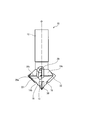
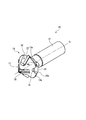
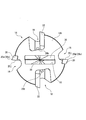
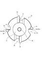
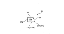
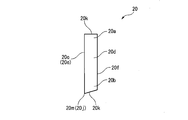
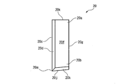
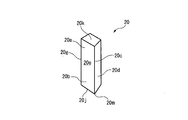
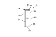
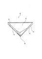
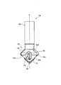
- FIG. 1st Embodiment of this invention It is a front view of the milling tool according to 1st Embodiment of this invention. It is a side view of the milling tool seen from the direction different from FIG. 1 by 90 °. It is a perspective view of the milling tool of FIG. It is a bottom view of the milling tool of FIG. 1 seen from the head side. It is a top view of the milling tool of FIG. 1 seen from the shank side. It is a front view of the upper insert used in the milling tool of FIG. It is a bottom view of the upper insert of FIG. It is a side view of the upper insert of FIG. It is a rear view of the upper insert of FIG. It is a perspective view of the upper insert of FIG.
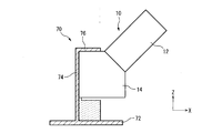
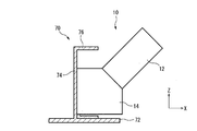
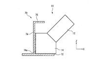
- FIG. 5 is a plan view showing an example of a work having a return flange machined by the milling tool of FIG. It is sectional drawing of the work of FIG. It is a schematic diagram for demonstrating the method of processing a rib having a return flange. It is a schematic diagram for demonstrating the method of processing a rib having a return flange.
- FIG. 28 is a side view of the milling tool viewed from a direction 90 ° different from that of FIG. 28. It is a perspective view of the milling tool of FIG. 28. It is a bottom view of the milling tool of FIG. 28 seen from the head side. It is a front view of the upper insert used in the milling tool of FIG. 28. It is a bottom view of the upper insert of FIG. 28. It is a side view of the upper insert of FIG. 28. It is a rear view of the upper insert of FIG. 28.
- FIG. 28 It is a perspective view of the upper insert of FIG. 28. It is a front view of the tip insert used in the milling tool of FIG. It is a perspective view seen from the tip side of the tip insert of FIG. 37. It is a side view of the tip insert of FIG. 37.
- FIG. 3 is a perspective view of the tip insert of FIG. 37 as viewed from another angle.
- FIG. 5 is an end view showing an example of a work having a corner R between the bottom wall and the rib and between the rib and the return flange and having a return flange machined by the milling tool of FIG. 28. It is a schematic diagram for demonstrating the machining of the corner R of the work of FIG. 41 by the milling tool according to 2nd Embodiment.
- FIG. 41 It is a schematic diagram for demonstrating the machining of the corner R of the work of FIG. 41 by the milling tool according to 2nd Embodiment. It is a front view of the milling tool according to the 3rd Embodiment of this invention. It is a side view of the milling tool seen from the direction different from FIG. 44 by 90 °. It is a perspective view of the milling tool of FIG. 44. It is a perspective view of the tip insert used in the milling tool of FIG. 44.
- the milling tool 10 according to the first embodiment of the milling tool of the present invention includes a columnar shank 12 and a head 14 integrally formed at the tip of the shank 12. doing.
- the head 14 has a substantially truncated cone-shaped diameter-expanded portion 14a whose diameter increases from the proximal end side in contact with the shank 12 toward the tip end, and a substantially truncated cone-shaped diameter reduction portion whose diameter further decreases in the distal end direction from the diameter-expanded portion 14a. It has a portion 14b and is formed in the shape of a truncated cone.
- a transition portion 14c as a maximum diameter portion having a maximum diameter is formed between the diameter expansion portion 14a and the diameter reduction portion 14b.
- the head 14 also has an upper groove 16 formed in the enlarged diameter portion 14a, a lower groove 18 formed in the reduced diameter portion 14b, and a tip groove 13 for attaching the tip insert 30.
- the upper groove 16 and the lower groove 18 are alternately arranged around the central axis O of the head 14 at equal angular intervals.
- the head 14 has two upper grooves 16 and two lower grooves 18.
- the upper groove 16 and the lower groove 18 are arranged at equal angle intervals, but they may be arranged at unequal angle intervals to prevent chatter vibration.
- Each of the upper grooves 16 is formed with an upper seat (not shown) to which the upper insert 20 is attached, and each of the lower grooves 18 is formed with a lower seat (not shown) to which the lower insert 22 is attached.
- the two upper inserts 20 are arranged in the enlarged diameter portion 14a and the two lower inserts 22 are arranged in the reduced diameter portion 14b.
- the upper insert 20 and the lower insert 22 are arranged.
- the number is not limited to 2, and at least one upper insert 20 and at least one lower insert 22 may be arranged. Therefore, each of the enlarged diameter portion 14a and the reduced diameter portion 14b may also have at least one upper groove 16 and a lower groove 18.
- the linear first cutting edge 20c (FIGS. 6 to 10) of the upper insert 20 attached to the upper seat gradually approaches the transition portion 14c in the rotation direction of the milling tool 10. It is formed so as to extend diagonally.
- the linear first cutting edge 22c (FIG. 11) of the lower insert 22 attached to the lower seat gradually approaches the transition portion 14c in the rotation direction of the milling tool 10. It is formed so as to extend diagonally.
- the milling tool 10 can be formed with a coolant passage for supplying coolant to the machining area.
- the coolant passage includes an inlet passage 24 that penetrates the shank 12 along the central axis O of the milling tool 10, and an upper radial passage 26a that penetrates the head 14 in the radial direction from the inlet passage 24 and opens into each upper groove 16.
- a lower radial passage 26b that opens into each lower groove 18.
- the upper insert 20 has an upper end portion 20a and a lower end portion 20b.
- the upper insert 20 is attached to the upper seat so that the lower end 20b is arranged in the vicinity of the transition 14c.
- the upper insert 20 also has a rake face 20e arranged on the opposite side of the upper seat when attached to the upper seat, and a first flank surface 20d facing outward in the radial direction.
- the upper surface 20k is oriented so as to face the shank 12, the back surface 20f on the opposite side of the rake face 20e, and the side surface on the opposite side of the first flank surface 20d.
- 20 g is in contact with the head 14, and the upper insert 20 is positioned with respect to the head 14 on these two surfaces.
- the rake surface 20e and the first flank surface 20d form a first cutting edge 20c that extends substantially linearly from the upper surface 20k to the lower surface 20h. Further, the lower surface 20h is inclined upward from the rake face 20e side to the back surface 20f side to form a second flank surface of the upper insert 20, and the upper side is formed by the rake face 20e and the second flank surface 20h. A second cutting edge 20j extending substantially linearly along the lower edge of the insert 20 is formed.
- the lower insert 22 is formed in substantially the same manner as the upper insert 20, and has an upper end portion 22a and a lower end portion 22b.
- the lower insert 22 is attached to the lower seat so that the upper end 22a is located in the vicinity of the transition 14c.
- the lower insert 22 also has a rake face (not shown) arranged on the opposite side of the lower seat when attached to the lower seat, and a first flank 22d directed outward in the radial direction. have.
- the lower surface 22k is directed toward the tip of the milling tool 10
- the back surface 22f on the opposite side of the rake face, and the opposite side of the first flank surface 22d The side surface 22g of the milling cutter is in contact with the head 14, and the lower insert 22 is positioned with respect to the head 14 on these two surfaces.
- the rake face and the first flank surface 22d form a first cutting edge 22c that extends substantially linearly from the upper surface 22h to the lower surface 22k.
- the upper surface 22h is inclined downward from the rake face side to the back surface 22f side to form a second flank surface of the lower insert 22, and the rake face and the second flank surface 22h form a lower side.
- a second cutting edge 22j extending substantially linearly along the upper edge of the insert 22 is formed.
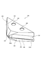
- the tip insert 30 is formed in a substantially triangular plate shape having vertices 38 in a plan view (side view of the milling tool 10 in FIG. 1).
- the tip insert 30 rotates about the apex 38 in the direction of the arrow 40.
- the tip insert 30 has two cutting edges 32 extending linearly from the apex 38 along the two sides of the triangle.
- the two cutting edges 32 are arranged on substantially the same straight line when the tip insert 30 is viewed from the tip side (vertex 38 side) (front view).
- the cutting edge 32 is formed by the line of intersection between the rake face 36 and the flank surface 34.
- the two rake faces 36 are formed so as to face the same direction with respect to the rotation direction of the milling tool 10.
- one of the two flanks 34 (the flank on the right side in FIG. 12) is below the cutting edge 32 formed by the flank, and the other flank 34 (the other flank 34).
- the flank on the left side in FIG. 12) is arranged above the cutting edge 32 formed by the flank.
- the upper insert 20 and the lower insert 22 have an upper seat and a lower seat so that the first cutting edges 20c and 22c, respectively, coincide with the central axis O of the milling tool 10 in the side view. It is attached to. Further, the upper insert 20 is attached to the upper seat so that when the milling tool 10 is rotated around the central axis O, the first cutting edge 20c of all the upper inserts 20 rotates along one conical surface. Be done. Similarly, the lower insert 22 is placed so that when the milling tool 10 is rotated around the central axis O, the first cutting edge of all lower inserts 22 rotates along one conical surface. Attached to the seat.
- the upper insert 20 and the lower insert 22 have the same intersection points 20m and 22m of the first and second cutting edges 20c, 20j; 22c and 22j, respectively, centered on the central axis O of the milling tool 10. It is attached to the upper and lower seats so that they are arranged on the circumference.
- first cutting edges 20c and 22c of the upper insert 20 and the lower insert 22 do not have to coincide with the central axis O of the milling tool 10 in the side view.
- the first cutting edge 20c of the upper insert 20 is inclined so as to extend diagonally backward from the intersection 20 m with respect to the rotation direction of the milling tool 10, and the first cutting edge of the lower insert 22
- the upper insert 20 and the lower insert 22 are attached so as to be inclined alternately.
- the first cutting edge 20c of the upper insert 20 is inclined so as to extend diagonally forward from the intersection 20 m with respect to the rotation direction of the milling tool 10, and the lower insert 22
- the first cutting edge 22c is inclined so as to extend diagonally forward from the intersection 22m with respect to the rotation direction of the milling tool 10, and the upper insert 20 and the lower insert 22 are attached to the upper and lower seats, respectively. You may. Also in this case, the upper insert 20 and the lower insert 22 are attached so as to be inclined alternately.
- the tip insert 30 is attached in the tip groove 13 formed at the tip of the head 14 so that the apex 38 is arranged on the central axis O of the milling tool 10. Further, the cutting edge 32 of the tip insert 30 is arranged so as to be in line with the straight line between the intersections 20m of the first and second cutting edges 20c and 20j of the two upper inserts 20.
- the two cutting edges 32 of the tip insert 30 rotate along the conical surface drawn by the first cutting edge of the lower insert 22 when the milling tool 10 is rotated around the central axis O, and the apex 38 Is attached to the tip groove 13 of the head 14 so as to be the apex of the conical surface. That is, the angle between the two cutting edges 32 sandwiching the apex 38 of the tip insert 30 is the central axis of the conical surface drawn by the first cutting edge 22c of the two lower inserts 22 (the central axis O of the milling tool 10). ) Is equal to the angle between the two generatrixes intersecting the conical surface.
- the two conical surfaces drawn by the first cutting edges 20c and 22c of the upper insert 20 and the lower insert 22 when the milling tool 10 rotates have a line of intersection between the two conical surfaces.
- it is symmetrical with respect to the specified plane, it may be asymmetrical depending on the target machining process and work shape.
- the line of intersection (the generatrix of each conical surface) between the plane including the central axis O and the two conical surfaces intersects at a predetermined angle. This angle can have various values depending on the target processing process.
- the angle formed by the two lines of intersection is, for example, an angle equal to the angle between the rib and the return flange protruding from the upper end of the rib, preferably 90 ° or an angle smaller than 90 °, as described later. Can be. Further, the first cutting edge 20c of the upper insert 20 is formed to be longer than the overhanging dimension (width) of the return flange.
- shank 12 and the head 14 are integrally formed by using tool steel, and the upper insert 20, the lower insert 22, and the tip insert 30 are formed of the head 14 by using an appropriate joining technique such as brazing. It can be attached to the upper and lower seats. A fixing screw (not shown) may be used to secure the upper insert 20, the lower insert 22, and the tip insert 30 to the head 14.
- the upper insert 20 and the lower insert 22 and the tip insert 30 After attaching the upper insert 20, the lower insert 22 and the tip insert 30, the upper insert 20, the lower insert 22 and the tip insert 30 are ground, and the two first cutting edges 20c of the upper insert 20 have the same cone. Draw a surface, the two first cutting edges 22c of the lower insert 22 and the two cutting edges 32 of the tip insert 30 draw the same conical surface, and the first and second cutting edges 20c of the upper insert 20 , The intersection 20m of 20j and the intersection 22m of the first and second cutting edges 22c and 22j of the lower insert 22 can draw the same circle.
- FIGS. 16 to 27 show an example of a work to be ribbed.
- the work 70 as a finished product has a bottom wall 72, a rib 74 forming a thin wall extending vertically from the bottom wall 72, and a return flange 76 protruding substantially parallel to the bottom wall 72 from the upper end of the rib 74.
- the work 70 is, for example, a 4-axis machining center having a linear feed axis of 3 orthogonal axes and at least one rotary feed axis, preferably a 5-axis having two rotary feed axes on the linear feed axis of 3 orthogonal axes.
- a machine tool such as a machining center (not shown)
- the milling tool 10 is attached to the tip of the spindle (not shown) of the machine tool, and the work 70 is scraped from a plank made of a metal material such as an aluminum alloy. Is issued.
- the milling tool 10 is attached to the tip of the spindle of the machine tool via a tool holder (not shown). Further, the work 70 is fixed to a table (not shown) of the machine tool.
- the width dimension of the return flange 76 for example, using a rotary tool such as a square end mill that can be cut on the side surface of the tool, a thin wall having a bottom wall 72 and ribs 74 as shown in FIG.
- the material is removed from the planks, leaving the return flange 76 and the portion to be removed (hereinafter referred to as the removal area) 78 between the return flange 76 and the bottom wall 72 (FIG. 18).
- positioning is performed in the Z-axis direction so that the finishing allowance ⁇ 1 remains with respect to the finished surface of the return flange 76, and positioning is performed in the X-axis direction so that the depth of cut from the surface of the removal region 78 is ⁇ X1.
- a part of the removal area 78 on the lower side of the return flange 76 is removed by the first roughing (FIG. 19). This first roughing is performed by all the cutting edges of the upper insert 20, the lower insert 22, and the tip insert 30.
- the return flange 76 is along the Z-axis without changing the inclination of the spindle.
- First finishing that removes the finishing allowance ⁇ 1 left on the lower surface of the return flange 76 of the work 70 while feeding the milling tool 10 in the Y-axis direction by giving a pick feed corresponding to the finishing allowance ⁇ 1 to the spindle in the direction approaching. Machining is performed (FIG. 20).
- the finishing process can be performed by using the same milling tool 10 at a higher spindle rotation speed than the rough process without replacing the milling tool 10.
- the first finishing process is mainly performed by the upper insert 20.
- the milling tool 10 is repositioned in the Z-axis direction so that the finishing allowance ⁇ 1 remains with respect to the finished surface of the return flange 76, and a further depth of cut ⁇ X2 is given in the X-axis direction.
- a further portion of the removal region 78 is removed by the second roughing (FIG. 21).
- the further depth of cut ⁇ X2 is determined so that the finishing allowance ⁇ 2 remains with respect to the finished surface of the rib 74.
- This second roughing is performed by the upper insert 20, the lower insert 22, and the tip insert 30.
- the pick feed corresponding to the finishing allowance ⁇ 1 is given to the spindle in the direction approaching the return flange 76 along the Z axis without changing the inclination of the spindle, and the milling tool 10 is Y.
- a second finishing process is performed while feeding in the axial direction to remove the finishing allowance ⁇ 1 left on the lower surface of the return flange 76 of the work 70 (FIG. 22). The second finishing process is performed by the upper insert 20.
- a pick feed corresponding to the finishing allowance ⁇ 2 is given to the spindle in the direction approaching the rib 74 along the X axis (in the illustrated embodiment, the milling tool 10 is fed to the left), and the milling tool 10 is moved in the Y axis direction.
- a third finishing process is performed to remove the finishing allowance ⁇ 2 left on the surface of the rib 74 of the work 70 (FIG. 23). The third finishing process is performed by the lower insert 22 and the tip insert 30.
- the milling tool 10 is repositioned in the Z-axis direction so that the finishing allowance ⁇ 3 remains with respect to the finished surface of the bottom wall 72, and a cut is made in the X-axis direction from the surface of the removal region 78.
- a third roughing process for further removing the removal region 78 is performed. At this time, this third roughing is performed by the lower insert 22 and the tip insert 30.
- a fourth rough machining for further removing the removal region 78 is executed by giving a further depth of cut ⁇ X4 (FIG. 24) along the X axis and feeding the milling tool 10 in the Y axis direction. At this time, this fourth roughing is performed by the lower insert 22 and the tip insert 30 (FIG. 25). The depth of cut ⁇ X4 is determined so that the finishing allowance ⁇ 4 remains with respect to the finished surface of the rib 74.
- a pick feed corresponding to the finishing allowance ⁇ 4 is given to the spindle in a direction approaching the rib 74 along the X axis, and the rib of the work 70 is fed while the milling tool 10 is fed in the Y axis direction.
- a fourth finishing process is performed to remove the finishing allowance ⁇ 4 left on the surface of 74 (FIG. 26). The fourth finishing process is performed by the lower insert 22 and the tip insert 30.
- a pick feed corresponding to the finishing allowance ⁇ 4 is given to the spindle in the direction away from the rib 74 along the X axis, and then a pick feed corresponding to the finishing allowance ⁇ 3 is given in the direction approaching the bottom wall 72 along the Z axis.
- a fifth finishing process is performed to remove the finishing allowance ⁇ 3 left on the surface of the rib 74 of the work 70 (FIG. 27).
- the fifth finishing process is performed by the lower insert 22 and the tip insert 30.
- the portion 74a remaining in the corner between the bottom wall 72 and the rib 74 is removed by the tip insert 30 of the milling tool 10.
- the work 70 having the bottom wall 72, the rib 74 extending vertically from the bottom wall 72, and the return flange 76 protruding substantially parallel to the bottom wall 72 from the upper end of the rib 74 is made of a metal plate material such as an aluminum alloy. It is possible to carve from.
- the work 70 can be, for example, a component of an aircraft wing.
- the removal region 78 is gradually processed from the tip side of the rib 74, so that the rigidity of the rib 74 is increased during the rib processing.
- the rib 74 is prevented from vibrating by keeping it as high as possible.
- the rib 74 and the return flange 76 are separated from each other. It is particularly advantageous for processing corners having no corners R, such as between the corners of the bottom wall 72 and the ribs 74.
- the milling tool 10 can be mounted on the spindle with a short protrusion length to process the rib 74 having the return flange 76.
- the tool By shortening the protrusion length, the tool usually has high static rigidity against bending and falling and dynamic rigidity against vibration, so that the rotation speed and feed rate of the tool can be increased. Therefore, by using the milling tool 10 according to the present embodiment, it is possible to process the work 70 with higher efficiency than when a tool such as a conventional T-shaped cutter is used. In addition, chatter vibration is less likely to occur, and the quality of the machined surface is improved.
- the angle between the generatrix of the conical surface drawn by the first cutting edge 20c of the upper insert 20 and the generatrix of the conical surface drawn by the first cutting edge 22c of the lower insert 22 is the rib 74.
- the apex angle of 30) is equal to the intersection angle of each finished surface of the bottom wall 72 and the rib 74, but the present invention is not limited to this.
- intersection angle of the first cutting edge of the upper insert 20 and the lower insert 22 may be equal to or less than the intersection angle of the finished surfaces of the rib 74 and the return flange 76. Further, the apex angle of the tip insert 30 may be an angle equal to or less than the intersection angle of the finished surfaces of the bottom wall 72 and the rib 74.
- the milling tool 100 includes a columnar shank 102 and a head 104 integrally formed at the tip of the shank 102.
- the head 104 has a substantially truncated cone-shaped diameter-expanded portion 104a whose diameter increases from the proximal end side in contact with the shank 102 toward the tip end, and a substantially truncated cone-shaped diameter reduction portion whose diameter further decreases in the distal end direction from the enlarged diameter portion 104a. It has a portion 104b and is formed in the shape of a truncated cone.
- a transition portion 104c as a maximum diameter portion having a maximum diameter is formed between the diameter expansion portion 104a and the diameter reduction portion 104b.
- the head 104 also has an upper groove 106 formed in the enlarged diameter portion 104a, a lower groove 108 formed in the reduced diameter portion 104b, and a tip groove 103 to which the tip insert 50 is attached.
- the upper groove 106 and the lower groove 108 are alternately arranged at equal angular intervals around the central axis O of the head 104.
- the head 104 has two upper grooves 106 and two lower grooves 108.
- the upper groove 106 and the lower groove 108 are arranged at equal angle intervals, but they may be arranged at unequal angle intervals to prevent chatter vibration.
- An upper seat (not shown) is formed in each of the upper grooves 106, and a lower seat (not shown) is formed in each of the lower grooves 108.
- An upper insert 120 is attached to each of the upper seats, and a lower insert 122 is attached to each of the lower seats.
- two upper inserts 120 are arranged in the enlarged diameter portion 104a and two lower inserts 122 are arranged in the reduced diameter portion 104b.
- the upper insert 120 and the lower insert 122 are arranged.
- the number is not limited to 2, and at least one upper insert 120 and at least one lower insert 122 may be arranged. Therefore, each of the enlarged diameter portion 104a and the reduced diameter portion 104b may also have at least one upper groove 106 and a lower groove 108.
- the milling tool 100 can be formed with a coolant passage for supplying coolant to the machining area.
- the coolant passage is an inlet passage (not shown) penetrating the shank 102 along the central axis O of the milling tool 100, and an upper side that passes through the head 104 in the radial direction from the inlet passage 24 and opens into each upper groove 106.
- a radial passage 126a and a lower radial passage 126b that opens into each lower groove 108 can be included.
- the upper insert 120 has an upper end portion 120a and a lower end portion 120b.
- the upper insert 120 is attached to the upper seat so that the lower end 120b is arranged in the vicinity of the transition 104c.
- the upper insert 120 also has a flank 120d that is disposed on the opposite side of the upper seat when attached to the upper seat.
- the upper insert 120 when the upper insert 120 is attached to the head 104, the upper surface 120k is oriented so as to face the shank 102, and the back surface 120f on the opposite side of the rake face 120e and the side surface 120g on the opposite side of the flank surface 120d are the heads. In contact with 104, the upper insert 120 is positioned with respect to the head 104 on these two surfaces.
- An arc-shaped first cutting edge 120c extending substantially linearly from the upper end portion 120a and an arc-shaped cutting edge 120c provided adjacent to the lower end portion 120b and connected to the first cutting edge 120c by the rake face 120e and the flank surface 120d.
- a second cutting edge 120j is formed.
- the lower insert 122 is formed in substantially the same manner.
- the upper insert 120 has the first cutting edge 120c of all the upper inserts 120 rotated along one conical surface when the milling tool 100 is rotated about the central axis O. It is attached to the upper seat so that it does.
- the lower insert 122 is such that when the milling tool 100 is rotated around the central axis O, the first cutting edge 122c of all the lower inserts 122 rotates along one conical surface. Attached to the lower seat.
- the tip insert 50 is formed in a substantially triangular plate shape having an apex 62 in a plan view (side view of the milling tool 100 in FIG. 28).
- the tip insert 50 has two cutting edges extending linearly from the apex 62 along the two sides of the triangle.
- the two cutting edges have an arcuate shape provided between the main cutting edge 52a extending substantially linearly and the apex 62 and the main cutting edge 52a in a plan view (side view of the milling tool 100 in FIG. 28). It has an auxiliary cutting edge 52b.
- Each of the two sets of cutting edges 52a and 52b is formed by the line of intersection of the rake face 56 and the flank face 54.
- one of the two rake faces 56 (the rake face on the right side in FIG. 37) is on the upper side of the cutting edges 52a and 52b formed by the rake face.
- the other rake face 56 (the rake face on the left side in FIG. 37) is arranged below the cutting edges 52a and 52b formed by the rake face.
- the two rake faces 36 are formed so as to face the same direction with respect to the rotation direction of the milling tool 10.
- one of the two flanks 54 (the flank on the right side in FIG. 37) is below the cutting edges 52a and 52b formed by the flanks, and the other flanks. 54 (the flank on the left side in FIG. 12) is arranged above the cutting edges 52a and 52b formed by the flank.
- the two linear main cutting edges 52a are extended in parallel with each other and do not intersect at the apex 62.
- Each of the two arcuate secondary cutting edges 52b is formed so as to be in contact with the linear main cutting edge 52a.
- the two arcuate secondary cutting edges 52b are formed so as to draw a common spherical surface when the milling tool 100 rotates around the central axis O in the vicinity of the apex 62. That is, in the plan view of the tip insert 50, the two auxiliary cutting edges 52b are arranged on a common arc.
- the tip insert 50 also has one chip discharge groove 58 provided adjacent to each of the main cutting edges 52a.
- the tip insert 50 also has two relief grooves 60 provided in the vicinity of the apex 62. Two secondary cutting edges 52b are arranged between the two relief grooves 60.
- the tip insert 50 is attached in the tip groove 103 formed at the tip of the head 104 so that the apex 62 is arranged on the central axis O of the milling tool 100. Further, the two main cutting edges 52a of the tip insert 50 rotate along the conical surface drawn by the first cutting edge 22c of the lower insert 122 when the milling tool 100 is rotated around the central axis O. It is attached to the tip groove 103 of the head 104. That is, the angle between the two main cutting edges 52a sandwiching the apex 62 of the tip insert 50 is the central axis of the conical surface drawn by the first cutting edge 22c of the two lower inserts 22 (the central axis of the milling tool 100). The plane containing O) is equal to the angle between the two generatrixes intersecting the conical surface.
- the two conical surfaces drawn by the first cutting edges 120c, 122c of the upper insert 120 and the lower insert 122 when the milling tool 100 rotates have a line of intersection between the two conical surfaces. Although it is symmetrical with respect to the specified plane, it may be asymmetrical depending on the target machining process and work shape. Further, the line of intersection (the generatrix of each conical surface) between the plane including the central axis O and the two conical surfaces intersects at a predetermined angle. This angle can have various values depending on the target processing process.
- the angle formed by the two lines of intersection is, for example, an angle equal to the angle between the rib and the return flange protruding from the upper end of the rib, preferably 90 ° or an angle smaller than 90 °, as described later. Can be. Further, the first cutting edge 120c of the upper insert 120 is formed to be longer than the overhanging dimension (width) of the return flange.
- the upper insert 120 and the lower insert 122 form one arc in which the second cutting edges 120j and 122j bulge in the radial direction of the head 104 when the milling tool 100 is rotated around the central axis O. It is attached to the upper seat and the lower seat so as to move along the shape of the rotating body, which is a locus when the milling tool 100 is rotated around the central axis O.
- the shape of the rotating body may be inscribed in both of the two conical surfaces drawn by the first cutting edges 120c and 122c of the upper insert 120 and the lower insert 122 when the milling tool 100 rotates. it can.
- tool steel is used to integrally form the shank 102 and the head 104, and the upper insert 120, lower insert 122 and tip insert 50 are made of the head 104 using an appropriate coupling technique such as brazing. It can be attached to the upper and lower seats. Fixing screws (not shown) may be used to secure the upper insert 120, lower insert 122 and tip insert 50 to the head 104.
- the upper insert 120, the lower insert 122 and the tip insert 50 After attaching the upper insert 120, the lower insert 122 and the tip insert 50, the upper insert 120, the lower insert 122 and the tip insert 50 are ground, and the two first cutting edges 120c of the upper insert 20 have the same cone.
- a surface can be drawn so that the two first cutting edges 122c of the lower insert 22 and the two cutting edges 32 of the tip insert 30 draw the same conical surface.
- the generatrix of each of the two conical surfaces drawn by the first cutting edge 120c of the upper insert 20 and the first cutting edge 122c of the lower insert 22 projects from the rib of the work and the upper end of the rib.
- the angle is equal to the angle with the return flange, and the shape of the rotating body drawn by the second cutting edges 120j and 122j can be inscribed in both of the two conical surfaces.
- the milling tool 100 can process ribs having a return flange in the same procedure as the milling tool 10 described with reference to FIGS. 16 to 27. As described above, the milling tool 10 is suitable for machining a corner having no corner R, while the milling tool 100 is suitable for machining a corner having a corner R as shown in FIG. 41.
- the work 80 includes a bottom wall 82, a rib 84 forming a thin wall extending vertically from the bottom wall 82, and a return flange 86 projecting from the upper end of the rib 84 to both sides substantially parallel to the bottom wall 82.
- a corner between the bottom wall 82 and the rib 84 and the corner between the rib 84 and the return flange 86 are corners R.
- the corner R between the bottom wall 82 and the rib 84 is machined by the secondary cutting edge 52b of the tip insert 50, and the corner R between the rib 84 and the return flange 86 is the upper insert 120 and the lower insert. It is processed by the second cutting edges 120j and 122j of 122.
- the milling tool 200 according to the third embodiment has substantially the same configuration as the milling tool 100 according to the second embodiment, and is formed on a cylindrical shank 202 and a tip of the shank 202. It includes an integrally formed head 204.
- the head 204 has a substantially truncated cone-shaped diameter-expanded portion 204a whose diameter increases from the proximal end side in contact with the shank 202 toward the tip end, and a substantially truncated cone-shaped diameter reduction portion whose diameter further decreases in the distal end direction from the enlarged diameter portion 204a. It has a portion 204b and is formed in the shape of a truncated cone.
- a transition portion 204c as a maximum diameter portion having a maximum diameter is formed between the diameter expansion portion 204a and the diameter reduction portion 204b.
- the head 204 also has an upper groove 206 formed in the enlarged diameter portion 204a, a lower groove 208 formed in the reduced diameter portion 204b, and a tip groove 203 for attaching the tip insert 230.
- the upper groove 206 and the lower groove 208 are alternately arranged around the central axis O of the head 204 at equal angular intervals.
- the head 204 has two upper grooves 206 and two lower grooves 208.
- the upper groove 206 and the lower groove 208 are alternately arranged at equal angular intervals around the central axis O of the head 204.
- the head 204 has two upper grooves 206 and two lower grooves 208.
- the upper groove 206 and the lower groove 208 are arranged at equal angle intervals, but they may be arranged at unequal angle intervals to prevent chatter vibration.
- An upper insert 220 is attached to each of the upper grooves 206, and a lower insert 222 is attached to each of the lower grooves 208.
- the upper insert 220 and the lower insert 222 are similar to the upper insert 120 and the lower insert 122 of the second embodiment.
- the tip insert 230 is formed in a substantially triangular plate shape having an apex 242.
- the tip insert 230 has two cutting edges extending linearly from the apex 242 along the two sides of the triangle.
- the two cutting edges are provided between the first cutting edge 232a extending substantially linearly and the apex 242 and the first cutting edge 232a in a plan view (side view of the milling tool 200 in FIG. 44). It has a second cutting edge 232b having an arc shape.
- Each of the two sets of cutting edges 232a and 232b is formed by the line of intersection of the rake face 236 and the flank face 234.
- the tip insert 230 is fixed to the head 204 by the fixing screw 212. Therefore, the head 204 has a notch 210 at its tip.
- the notch 210 is formed with a screw hole (not shown) for screwing the fixing screw 212, and the tip insert 230 is formed with a recess 240 similar to the tip shape of the fixing screw 212.
- the upper inserts 20, 120, 220 and the lower inserts 22, 122, 222 are each two, and the tip inserts 30, 50, 230 are one each.
- the present invention is not limited to this, and at least one upper insert and at least one lower insert may be provided.
- the main cutting edge of the upper insert, the secondary cutting edge around the maximum diameter, the main cutting edge of the lower insert, the main cutting edge of the tip insert and the tip cutting edge are divided or integrated into a plurality of cutting edges. It may be an insert type or a solid type tool provided with.
Landscapes
- Engineering & Computer Science (AREA)
- Mechanical Engineering (AREA)
- Milling Processes (AREA)
Abstract
フライス工具(10)がシャンク部(12)と、該シャンク部の先端側に設けられ、切れ刃を有するヘッド(14)とで構成され、ヘッド(14)は、シャンク部(12)に接する基端部から先端方向に直径が次第に拡大する拡径部(14a)と、最大直径部(14c)から先端方向に直径が次第に縮小する縮径部(14b)とを含み、拡径部(14a)および縮径部(14b)の各々に少なくとも1つの切れ刃2(0、22)が設けられ、ヘッドの先端部において、少なくとも1つの先端切れ刃(32)が縮径部からフライス工具の軸心まで延設されている。
Description
本発明は、リターンフランジを有したリブのようなアンダーカット部を高効率かつ高精度に加工可能なフライス工具およびワークの加工方法に関する。
特許文献1には、ワーク側面にアンダーカットを形成するT形カッタが記載されている。該T形カッタは、シャンクの一端に結合されたヘッドを有しており、該ヘッドの先端側に切れ刃を有した複数の底刃部と、基端側に切れ刃を有した複数の上刃部とが周方向に交互に配置されており、前記底刃部および前記上刃部の切れ刃が、前記シャンクおよび前記ヘッドと一体構造をなしている。
特許文献1のT形カッタは、底刃部、上刃部、シャンクおよびヘッドが一体構造をなしているので、剛性が高く高効率でアンダーカット加工することが可能である。然しながら、リブの高さが高くなると、それだけシャンクを長くしなければならず、シャンクには大きな横方向の力(曲げ応力)が作用してシャンクが変形し、加工速度や加工精度が低下する問題がある。
本発明は、こうした従来技術の問題を解決することを技術課題としており、リターンフランジを有したリブのようなアンダーカット部を高効率かつ高精度に加工可能なフライス工具およびワークの加工方法を提供することを目的とする。
上述の目的を達成するために、本発明によれば、シャンク部と、該シャンク部の先端側に設けられ、切れ刃を有するヘッドとで構成されたフライス工具において、前記ヘッドは、前記シャンク部に接する基端部から先端方向に直径が次第に拡大する拡径部と、最大直径部から先端方向に直径が次第に縮小する縮径部とを含み、前記拡径部および前記縮径部の各々に設けられた少なくとも1つの切れ刃と、前記ヘッドの先端部において、前記縮径部から前記フライス工具の軸心まで延設された少なくとも1つの先端切れ刃とを具備したフライス工具が提供される。
また、本発明によれば、工作機械のテーブルに固定されたワークのリブと該リブに続けて形成されるリターンフランジとの内側部分をアンダーカットするワークの加工方法において、請求項1に記載のフライス工具を前記工作機械の主軸に取り付けて回転させ、前記フライス工具の前記拡径部の切れ刃でリターンフランジの内側を加工し、前記フライス工具の前記縮径部の切れ刃および先端切れ刃でリブの側面およびリターンフランジの内側とリブの側面との間の隅部を加工するワークの加工方法が提供される。
本発明によれば、フライス工具のヘッドが、基端部から先端方向に直径が次第に拡大する拡径部と、最大直径部から先端方向に直径が次第に縮小する縮径部とを含み、前記拡径部および前記縮径部に切れ刃を設けたので、フライス工具をワークのアンダーカット部に斜めに接近させて、リターンフランジと干渉することなくワークの加工が可能となるので、シャンクの突き出し長さを短くすることが可能となる。従って、アンダーカット部を高い加工条件で効率よく、高精度、高品位に加工することができる。また、フライス工具の軸心まで延設された先端切れ刃によって、リターンフランジの内側とリブの側面との間の隅部も本工具1本で加工でき、ワークの加工時間が短縮する。
また、少なくとも1つの先端切れ刃をヘッドの先端部において縮径部からフライス工具の軸心まで延設したので、底壁とリブ、リターンフランジのような平面加工と同時に、底壁とリブとの間の隅部のや、リブとリターンフランジとの間の隅部の加工が可能となり、アンダーカット部を一層効率よく加工可能となる。
以下、添付図面を参照して、本発明の好ましい実施の形態を説明する。
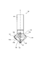
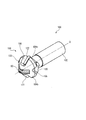
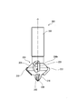
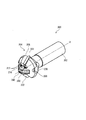
図1~図15を参照すると、本発明のフライス工具の第1の実施の形態によるフライス工具10は、円柱状のシャンク12と、シャンク12の先端に一体的に形成されたヘッド14とを具備している。ヘッド14は、シャンク12に接する基端側から先端方向に直径が拡大する略円錐台形状の拡径部14aと、拡径部14aから更に先端方向に直径が縮小する略円錐台形状の縮径部14bとを有し、概ね算盤玉の形状に形成されている。拡径部14aと縮径部14bとの間に直径が最大となる最大直径部としての遷移部14cが形成されている。ヘッド14は、また、拡径部14aに形成された上側溝16と、縮径部14bに形成された下側溝18と、先端インサート30を取り付ける先端溝13とを有している。
図1~図15を参照すると、本発明のフライス工具の第1の実施の形態によるフライス工具10は、円柱状のシャンク12と、シャンク12の先端に一体的に形成されたヘッド14とを具備している。ヘッド14は、シャンク12に接する基端側から先端方向に直径が拡大する略円錐台形状の拡径部14aと、拡径部14aから更に先端方向に直径が縮小する略円錐台形状の縮径部14bとを有し、概ね算盤玉の形状に形成されている。拡径部14aと縮径部14bとの間に直径が最大となる最大直径部としての遷移部14cが形成されている。ヘッド14は、また、拡径部14aに形成された上側溝16と、縮径部14bに形成された下側溝18と、先端インサート30を取り付ける先端溝13とを有している。
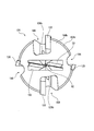
上側溝16と下側溝18とはヘッド14の中心軸線O周りに交互に等角度間隔で配置されている。図示する実施形態では、ヘッド14は、2つの上側溝16と、2つの下側溝18とを有している。なお、本実施形態では上側溝16と下側溝18は等角度間隔で配置されているが、びびり振動防止のため不等角度間隔で配置されていてもよい。
上側溝16の各々には、上側インサート20を取り付ける上側座(図示せず)が形成され、下側溝18の各々には、下側インサート22が取り付けられる下側座(図示せず)が形成されている。図示する実施形態では、拡径部14aに2つの上側インサート20が配置され、縮径部14bに2つの下側インサート22が配置されているが、本発明において上側インサート20および下側インサート22の個数は2に限定されず、少なくとも1つの上側インサート20と、少なくとも1つの下側インサート22が配置されていればよい。従って、拡径部14aおよび縮径部14bの各々も少なくとも1つの上側溝16および下側溝18を備えていればよい。
上側座は、該上側座に取り付けられた上側インサート20の直線状の第1の切れ刃20c(図6~図10)が、該フライス工具10の回転方向に次第に遷移部14cに接近する方向に斜めに延びるように形成されている。下側座は、該下側座に取り付けられた下側インサート22の直線状の第1の切れ刃22c(図11)が、該フライス工具10の回転方向に次第に遷移部14cに接近する方向に斜めに延びるように形成されている。
更に、フライス工具10には加工領域にクーラントを供給するためのクーラント通路を形成することができる。該クーラント通路は、フライス工具10の中心軸線Oに沿ってシャンク12を貫通する入口通路24、該入口通路24から半径方向にヘッド14を貫通して各上側溝16に開口する上側半径方向通路26a、および、各下側溝18に開口する下側半径方向通路26bを含むことができる。
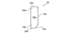
図6~図10を参照すると、上側インサート20は上端部20aと下端部20bとを有している。上側インサート20は、下端部20bが遷移部14cの近傍に配置されるように上側座に取り付けられる。上側インサート20は、また、上側座に取り付けたとき、該上側座とは反対側に配置されるすくい面20eと、半径方向外側に向けられる第1の逃げ面20dとを有している。このように、上側インサート20がヘッド14に取り付けられると、上面20kがシャンク12を臨むように配向され、すくい面20eの反対側の背面20f、および、第1の逃げ面20dの反対側の側面20gがヘッド14に接し、この2つの表面で上側インサート20はヘッド14に対して位置決めされる。
すくい面20eと第1の逃げ面20dとによって、上面20kから下面20hへ概ね直線状に延びる第1の切れ刃20cが形成される。また、下面20hは、すくい面20e側から背面20f側に上方へ傾斜して、上側インサート20の第2の逃げ面を形成しており、すくい面20eと第2の逃げ面20hとによって、上側インサート20の下縁部に沿って概ね直線状に延びる第2の切れ刃20jが形成される。
図11を参照すると、下側インサート22は上側インサート20と概ね同様に形成されており、上端部22aと下端部22bとを有している。下側インサート22は、上端部22aが遷移部14cの近傍に配置されるように下側座に取り付けられる。下側インサート22は、また、下側座に取り付けたとき、該下側座とは反対側に配置されるすくい面(図示せず)と、半径方向外側に向けられる第1の逃げ面22dとを有している。このように、下側インサート22がヘッド14に取り付けられたとき、下面22kがフライス工具10の先端方向に向けられ、すくい面の反対側の背面22f、および、第1の逃げ面22dの反対側の側面22gがヘッド14に接し、この2つの表面で下側インサート22はヘッド14に対して位置決めされる。
すくい面と第1の逃げ面22dとによって、上面22hから下面22kへ概ね直線状に延びる第1の切れ刃22cが形成される。また、上面22hは、すくい面側から背面22f側に下方へ傾斜して、下側インサート22の第2の逃げ面を形成しており、すくい面と第2の逃げ面22hとによって、下側インサート22の上縁部に沿って概ね直線状に延びる第2の切れ刃22jが形成される。
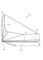
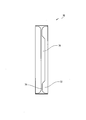
先端インサート30は、図13に示すように、平面視(図1ではフライス工具10の側面視)において、頂点38を有した略三角形状の板状に形成される。先端インサート30は、頂点38を中心として矢印40の方向に回転する。先端インサート30は、頂点38から上記三角形の2辺に沿って直線状に延びる2つの切れ刃32を有している。2つの切れ刃32は、先端インサート30を先端側(頂点38側)から見たとき(正面視)、概ね同一の直線上に配置される。切れ刃32は、すくい面36と逃げ面34との交線によって形成される。先端インサートを先端側から見たとき、2つのすくい面36の一方(図12では右側のすくい面)は、該すくい面が形成する切れ刃32の上側に、他方のすくい面36(図12では左側のすくい面)は、該すくい面が形成する切れ刃32の下側に配置される。こうして、2つのすくい面36は、フライス工具10の回転方向に関して同じ方向に向くように形成される。また、先端インサートを先端側から見たとき、2つの逃げ面34の一方(図12では右側の逃げ面)は、該逃げ面が形成する切れ刃32の下側に、他方の逃げ面34(図12では左側の逃げ面)は、該逃げ面が形成する切れ刃32の上側に配置される。
本実施形態では、上側インサート20と下側インサート22は、各々の第1の切れ刃20c、22cが、側面視において、フライス工具10の中心軸線Oに一致するように、上側座と下側座に取り付けられている。更に、上側インサート20は、フライス工具10を中心軸線O周りに回転させたときに、全ての上側インサート20の第1の切れ刃20cが1つの円錐面に沿って回転するように上側座に取り付けられる。同様に、下側インサート22は、フライス工具10を中心軸線O周りに回転させたときに、全ての下側インサート22の第1の切れ刃が1つの円錐面に沿って回転するように下側座に取り付けられる。また、上側インサート20と、下側インサート22は、各々の第1と第2の切れ刃20c、20j;22c、22jの交点20m、22mが、フライス工具10の中心軸線Oを中心とした同一の円周上に配置されるように、上側座および下側座に取り付けられる。
なお、上側インサート20および下側インサート22は、各々の第1の切れ刃20c、22cが、側面視において、フライス工具10の中心軸線Oに一致していなくてもよい。例えば、側面視において、上側インサート20の第1の切れ刃20cが、フライス工具10の回転方向に対して、交点20mから斜め後方に延びるように傾斜し、下側インサート22の第1の切れ刃22cが、フライス工具10の回転方向に対して、交点22mから斜め後方に延びるように傾斜するように、上側インサート20と、下側インサート22とを上側座および下側座に取り付けるようにしてもよい。この場合、上側インサート20と下側インサート22とは、互い違いに傾斜して取り付けられる。
更には、フライス工具10の側面視において、上側インサート20の第1の切れ刃20cが、フライス工具10の回転方向に対して、交点20mから斜め前方に延びるように傾斜し、下側インサート22の第1の切れ刃22cが、フライス工具10の回転方向に対して、交点22mから斜め前方に延びるように傾斜し、上側インサート20および下側インサート22をそれぞれ上側座および下側座に取り付けるようにしてもよい。この場合も、上側インサート20と下側インサート22とは、互い違いに傾斜して取り付けられる。
先端インサート30は、図4に示すように、頂点38がフライス工具10の中心軸線O上に配置されるように、ヘッド14の先端部に形成された先端溝13内に取り付けられる。また、先端インサート30の切れ刃32は、2つの上側インサート20の第1と第2の切れ刃20c、20jの交点20m間の直線に対して一直線となるように配置される。
更に、先端インサート30の2つの切れ刃32は、フライス工具10を中心軸線O周りに回転させたときに、下側インサート22の第1の切れ刃が描く円錐面に沿って回転し、頂点38が該円錐面の頂点となるように、ヘッド14の先端溝13に取り付けられる。つまり、先端インサート30の頂点38を挟んだ2つの切れ刃32の間の角度は、2つの下側インサート22の第1の切れ刃22cが描く円錐面の中心軸線(フライス工具10の中心軸線O)を含む平面が、該円錐面と交差する2本の母線間の角度に等しくなっている。
図示する実施形態では、フライス工具10が回転するときに上側インサート20と下側インサート22の第1の切れ刃20c、22cが描く2つの円錐面は、該2つの円錐面の間の交線が規定する平面に対して対称となっているが、目的とする加工プロセスやワーク形状によっては非対称でもよい。また、中心軸線Oを含む平面と、上記2つの円錐面との間の交線(各円錐面の母線)は所定の角度で交差する。この角度は、目的とする加工プロセスに応じて種々な値とすることができる。上記2つの交線が形成する角度は、例えば、後述するようにリブと、該リブの上端から張り出したリターンフランジとの間の角度に一致する角度、好ましくは90°または90°よりも小さな角度とすることができる。また、上側インサート20の第1の切れ刃20cは、上記リターンフランジの張り出し寸法(幅)よりも長く形成される。
また、工具鋼を用いてシャンク12とヘッド14とを一体的に形成し、上側インサート20、下側インサート22および先端インサート30は、ろう付けのような適当な結合技術を用いてこのヘッド14の上側座および下側座に取り付けることができる。固定ねじ(図示せず)を用いて、上側インサート20、下側インサート22および先端インサート30をヘッド14に固定するようにしてもよい。
上側インサート20、下側インサート22および先端インサート30を取り付けた後に、上側インサート20、下側インサート22および先端インサート30に研削加工を施し、上側インサート20の2つの第1の切れ刃20cが同一円錐面を描き、下側インサート22の2つの第1の切れ刃22cと先端インサート30の2つの切れ刃32とが同一円錐面を描き、かつ、上側インサート20の第1と第2の切れ刃20c、20jの交点20mと、下側インサート22の第1と第2の切れ刃22c、22jの交点22mとが同一の円を描くようにすることができる。
以下、図16~図27を参照して、フライス工具10を用いたリブ加工(アンダーカット)方法の一例を説明する。
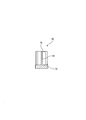
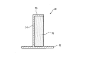
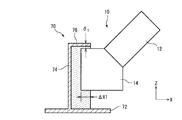
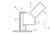
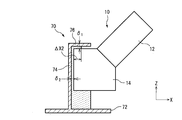
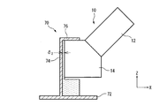
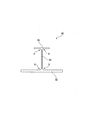
図16~図18は、リブ加工を行うワークの一例を示している。加工が完了した製品としてのワーク70は、底壁72、底壁72から垂直に延びる薄壁を形成するリブ74、および、リブ74の上端から底壁72に概ね平行に突出したリターンフランジ76を有している。ワーク70は、例えば、直交3軸の直線送り軸と少なくとも1つの回転送り軸とを有した4軸のマシニングセンタ、好ましくは直交3軸の直線送り軸に2つの回転送り軸を有した5軸のマシニングセンタのような工作機械(図示せず)で、フライス工具10を前記工作機械の主軸(図示せず)の先端に装着して、アルミニウム合金のような金属材料で成る厚板からワーク70が削り出される。なお、フライス工具10は、工具ホルダ(図示せず)を介して工作機械の主軸の先端に取り付けられている。また、ワーク70は工作機械のテーブル(図示せず)に固定される。
図16~図18は、リブ加工を行うワークの一例を示している。加工が完了した製品としてのワーク70は、底壁72、底壁72から垂直に延びる薄壁を形成するリブ74、および、リブ74の上端から底壁72に概ね平行に突出したリターンフランジ76を有している。ワーク70は、例えば、直交3軸の直線送り軸と少なくとも1つの回転送り軸とを有した4軸のマシニングセンタ、好ましくは直交3軸の直線送り軸に2つの回転送り軸を有した5軸のマシニングセンタのような工作機械(図示せず)で、フライス工具10を前記工作機械の主軸(図示せず)の先端に装着して、アルミニウム合金のような金属材料で成る厚板からワーク70が削り出される。なお、フライス工具10は、工具ホルダ(図示せず)を介して工作機械の主軸の先端に取り付けられている。また、ワーク70は工作機械のテーブル(図示せず)に固定される。
まず、リターンフランジ76の幅寸法に合わせて、例えば、工具の側面で切削可能なスクエアエンドミルのような回転工具を用いて、図18に示すような、底壁72、リブ74となる薄壁、リターンフランジ76、および、リターンフランジ76と底壁72との間の除去すべき部分(以下、除去領域と称する)78を残して、前記厚板から材料が除去される(図18)。
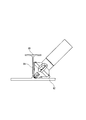
次に、リターンフランジ76の仕上げ面に対して仕上げ代δ1が残るようにZ軸方向に位置決めすると共に、除去領域78の表面からの切込み量がΔX1となるようにX軸方向に位置決めして、フライス工具10をY軸方向(紙面に垂直な方向)に送ることによって、リターンフランジ76の下側の除去領域78の一部が第1の荒加工により除去される(図19)。この第1の荒加工は、上側インサート20、下側インサート22および先端インサート30の全ての切れ刃によって行われる。
ワーク70の全長に亘ってフライス工具10をY軸方向(紙面に垂直な方向)に送り、第1の荒加工が終了すると、主軸の傾きを変更することなく、Z軸に沿ってリターンフランジ76に接近する方向に仕上げ代δ1に相当するピックフィードを主軸に与え、フライス工具10をY軸方向に送りつつ、ワーク70のリターンフランジ76の下面に残した仕上げ代δ1を除去する第1の仕上げ加工が実行される(図20)。仕上げ加工は、フライス工具10を交換することなく、同じフライス工具10を用いて荒加工よりも高い主軸回転速度で行うことができる。また、第1の仕上げ加工は、主に上側インサート20によって行われる。
次いで、図21に示すように、リターンフランジ76の仕上げ面に対して仕上げ代δ1が残るようにZ軸方向に再び位置決めすると共に、X軸方向に更なる切込み量ΔX2を与え、フライス工具10をY軸方向に送ることによって、除去領域78の更なる一部が、第2の荒加工により除去される(図21)。このとき、更なる切込み量ΔX2は、リブ74の仕上げ面に対して仕上げ代δ2が残るように決定される。この第2の荒加工は、上側インサート20、下側インサート22および先端インサート30によって行われる。
第2の荒加工が完了した後、主軸の傾きを変更することなく、Z軸に沿ってリターンフランジ76に接近する方向に仕上げ代δ1に相当するピックフィードを主軸に与え、フライス工具10をY軸方向に送りつつ、ワーク70のリターンフランジ76の下面に残した仕上げ代δ1を除去する第2の仕上げ加工が実行される(図22)。第2の仕上げ加工は、上側インサート20によって行われる。
次いで、X軸に沿ってリブ74に接近する方向に仕上げ代δ2に相当するピックフィードを主軸に与え(図示する実施形態では、フライス工具10を左方へ送り込む)フライス工具10をY軸方向に送りつつ、ワーク70のリブ74の表面に残した仕上げ代δ2を除去する第3の仕上げ加工が実行される(図23)。第3の仕上げ加工は、下側インサート22と、先端インサート30とによって行われる。
次いで、図24に示すように、底壁72の仕上げ面に対して仕上げ代δ3が残るように、フライス工具10をZ軸方向に再び位置決めすると共に、除去領域78の表面からX軸方向に切込み量ΔX3を与え、フライス工具10をY軸方向に送ることによって、除去領域78を更に除去する第3の荒加工が実行される。このとき、この第3の荒加工は、下側インサート22および先端インサート30によって行われる。
次いで、X軸に沿って更なる切込み量ΔX4(図24)を与え、フライス工具10をY軸方向に送ることによって、除去領域78を更に除去する第4の荒加工が実行される。このとき、この第4の荒加工は、下側インサート22および先端インサート30によって行われる(図25)。切込み量ΔX4は、リブ74の仕上げ面に対して仕上げ代δ4が残るように決定される。
第4の荒加工が完了した後、X軸に沿ってリブ74に接近する方向に仕上げ代δ4に相当するピックフィードを主軸に与え、フライス工具10をY軸方向に送りつつ、ワーク70のリブ74の表面に残した仕上げ代δ4を除去する第4の仕上げ加工が実行される(図26)。第4の仕上げ加工は、下側インサート22と、先端インサート30とによって行われる。
次いで、X軸に沿ってリブ74から離反する方向に仕上げ代δ4に相当するピックフィードを主軸に与えた後に、Z軸に沿って底壁72に接近する方向に仕上げ代δ3に相当するピックフィードを主軸に与え、フライス工具10をY軸方向に送りつつ、ワーク70のリブ74の表面に残した仕上げ代δ3を除去する第5の仕上げ加工が実行される(図27)。第5の仕上げ加工は、下側インサート22と、先端インサート30とによって行われる。最後に、底壁72とリブ74との間の隅部に残った部分74aが、フライス工具10の先端インサート30によって除去される。
こうして、底壁72、底壁72から垂直に延びるリブ74、および、リブ74の上端から底壁72に概ね平行に突出したリターンフランジ76を有したワーク70がアルミニウム合金等の金属製厚板材料から削り出すことが可能となる。ワーク70は、例えば航空機の翼の部品とすることができる。
既述の加工方法では、リターンフランジ76を有したリブ74の加工(アンダーカット)において、リブ74の先端側から徐々に、除去領域78を加工することによって、リブ加工の間にリブ74の剛性が、なるべく高く維持されるようにして、リブ74が振動することを防止している。
このように、本実施形態は、三角柱状の先端インサート30の2つの切れ刃32が直線状に形成され、かつ、1つの頂点38で交差しているので、リブ74とリターンフランジ76との間の隅部や、底壁72とリブ74との間のように、コーナーRを有しない隅部の加工に特に有利である。
また、本実施形態によれば、フライス工具10は、短い突き出し長さで主軸に装着して、リターンフランジ76を有したリブ74の加工を行うことができる。突き出し長さを短くすることによって、通常、工具は湾曲や倒れに対する静剛性も、振動に対する動剛性も高くなるので、工具の回転速度や送り速度を高くすることが可能となる。従って、本実施形態によるフライス工具10を用いることによって、従来のT形カッタ等の工具を用いた場合よりも、高効率にワーク70を加工することが可能となる。また、びびり振動が発生しにくく、加工面品位も向上する。
本実施形態では、上側インサート20の第1の切れ刃20cが描く円錐面の母線と、下側インサート22の第1の切れ刃22cが描く円錐面の母線との間の角度が、リブ74とリターンフランジ76の各々の仕上げ面の交差角度(上側インサート20と下側インサート22の第1の切れ刃の交差角度)と等しく、かつ、先端インサート30の2つの切れ刃32がなす角度(先端インサート30の頂角)が底壁72とリブ74の各々の仕上げ面の交差角度と等しくなっているが、本発明は、これに限定されない。上側インサート20と下側インサート22の第1の切れ刃の交差角度は、リブ74とリターンフランジ76の各々の仕上げ面の交差角度以下であればよい。また、先端インサート30の頂角は、底壁72とリブ74の各々の仕上げ面の交差角度以下の角度であればよい。
図28~図40を参照して、本発明の第2の実施形態を説明する。
フライス工具100は、円柱状のシャンク102と、シャンク102の先端に一体的に形成されたヘッド104とを具備している。ヘッド104は、シャンク102に接する基端側から先端方向に直径が拡大する略円錐台形状の拡径部104aと、拡径部104aから更に先端方向に直径が縮小する略円錐台形状の縮径部104bとを有し、概ね算盤玉の形状に形成されている。拡径部104aと縮径部104bとの間に直径が最大となる最大直径部としての遷移部104cが形成されている。ヘッド104は、また、拡径部104aに形成された上側溝106と、縮径部104bに形成された下側溝108と、先端インサート50を取り付ける先端溝103とを有している。
フライス工具100は、円柱状のシャンク102と、シャンク102の先端に一体的に形成されたヘッド104とを具備している。ヘッド104は、シャンク102に接する基端側から先端方向に直径が拡大する略円錐台形状の拡径部104aと、拡径部104aから更に先端方向に直径が縮小する略円錐台形状の縮径部104bとを有し、概ね算盤玉の形状に形成されている。拡径部104aと縮径部104bとの間に直径が最大となる最大直径部としての遷移部104cが形成されている。ヘッド104は、また、拡径部104aに形成された上側溝106と、縮径部104bに形成された下側溝108と、先端インサート50を取り付ける先端溝103とを有している。
上側溝106と下側溝108とは、ヘッド104の中心軸線O周りに交互に等角度間隔で配置されている。図示する実施形態では、ヘッド104は、2つの上側溝106と、2つの下側溝108とを有している。なお、本実施形態では上側溝106と下側溝108は等角度間隔で配置されているが、びびり振動防止のため不等角度間隔で配置されていてもよい。
上側溝106の各々には上側座(図示せず)が形成され、下側溝108の各々には下側座(図示せず)が形成されている。上側座の各々には上側インサート120が取り付けられ、下側座の各々には下側インサート122が取り付けられる。図示する実施形態では、拡径部104aに2つの上側インサート120が配置され、縮径部104bに2つの下側インサート122が配置されているが、本発明において上側インサート120および下側インサート122の個数は2に限定されず、少なくとも1つの上側インサート120と、少なくとも1つの下側インサート122が配置されていればよい。従って、拡径部104aおよび縮径部104bの各々も少なくとも1つの上側溝106および下側溝108を備えていればよい。
更に、フライス工具100には加工領域にクーラントを供給するためのクーラント通路を形成することができる。該クーラント通路は、フライス工具100の中心軸線Oに沿ってシャンク102を貫通する入口通路(図示せず)、該入口通路24から半径方向にヘッド104を貫通して各上側溝106に開口する上側半径方向通路126a、および、各下側溝108に開口する下側半径方向通路126bとを含むことができる。
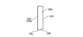
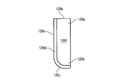
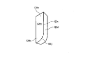
図32~図36を参照すると、上側インサート120は上端部120aと下端部120bとを有している。上側インサート120は、下端部120bが遷移部104cの近傍に配置されるように上側座に取り付けられる。上側インサート120は、また、上側座に取り付けたとき、該上側座とは反対側に配置される逃げ面120dとを有している。
このように、上側インサート120がヘッド104に取り付けられると、上面120kがシャンク102を臨むように配向され、すくい面120eの反対側の背面120f、および、逃げ面120dの反対側の側面120gがヘッド104に接し、この2つの表面で上側インサート120はヘッド104に対して位置決めされる。
すくい面120eと逃げ面120dとによって、上端部120aから概ね直線状に延びる第1の切れ刃120cと、下端部120bに隣接して設けられ、第1の切れ刃120cに連結される円弧状の第2の切れ刃120jが形成される。
下側インサート122も概ね同様に形成される。
下側インサート122も概ね同様に形成される。
図29~図30を参照すると、上側インサート120は、フライス工具100を中心軸線O周りに回転させたときに、全ての上側インサート120の第1の切れ刃120cが1つの円錐面に沿って回転するように、上側座に取り付けられる。同様に、下側インサート122は、フライス工具100を中心軸線O周りに回転させたときに、全ての下側インサート122の第1の切れ刃122cが1つの円錐面に沿って回転するように、下側座に取り付けられる。
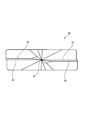
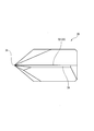
先端インサート50は、図38に示すように、平面視(図28ではフライス工具100の側面視)において、頂点62を有した略三角形状の板状に形成される。先端インサート50は、頂点62から上記三角形の2辺に沿って直線状に延びる2つの切れ刃を有している。該2つの切れ刃は、平面視(図28ではフライス工具100の側面視)において、概ね直線状に延びる主切れ刃52aと、頂点62と主切れ刃52aとの間に設けられた円弧状の副切れ刃52bとを有している。2組の切れ刃52a、52bの各々は、すくい面56と、逃げ面54との交線によって形成される。
矢印40の方向に回転する先端インサート50を先端側から見たとき、2つのすくい面56の一方(図37では右側のすくい面)は、該すくい面が形成する切れ刃52a、52bの上側に、他方のすくい面56(図37では左側のすくい面)は、該すくい面が形成する切れ刃52a、52bの下側に配置される。こうして、2つのすくい面36は、フライス工具10の回転方向に関して同じ方向に向くように形成される。また、先端インサートを先端側から見たとき、2つの逃げ面54の一方(図37では右側の逃げ面)は、該逃げ面が形成する切れ刃52a、52bの下側に、他方の逃げ面54(図12では左側の逃げ面)は、該逃げ面が形成する切れ刃52a、52bの上側に配置される。
また、2本の直線状の主切れ刃52aは、互いに平行に延設されており、頂点62では交差していない。2本の円弧状の副切れ刃52bの各々は、直線状の主切れ刃52aに接するように形成されている。2本の円弧状の副切れ刃52bは、頂点62の近傍において、フライス工具100が中心軸線O周りに回転したときに、共通の球面を描くように形成されている。つまり、先端インサート50の平面視において、2本の副切れ刃52bは、共通の円弧上に配置される。
先端インサート50は、また、主切れ刃52aの各々に隣接して設けられた1本の切り屑排出溝58を有している。先端インサート50は、また、頂点62の近傍に設けられた2本の逃げ溝60を有している。2本の逃げ溝60の間に、2本の副切れ刃52bが配置されている。
先端インサート50は、図28、29に示すように、頂点62がフライス工具100の中心軸線O上に配置されるように、ヘッド104の先端部に形成された先端溝103内に取り付けられる。更に、先端インサート50の2つの主切れ刃52aは、フライス工具100を中心軸線O周りに回転させたときに、下側インサート122の第1の切れ刃22cが描く円錐面に沿って回転するように、ヘッド104の先端溝103に取り付けられる。つまり、先端インサート50の頂点62を挟んだ2つの主切れ刃52aの間の角度は、2つの下側インサート22の第1の切れ刃22cが描く円錐面の中心軸線(フライス工具100の中心軸線O)を含む平面が、該円錐面と交差する2本の母線間の角度に等しくなっている。
図示する実施形態では、フライス工具100が回転するときに上側インサート120および下側インサート122の第1の切れ刃120c、122cが描く2つの円錐面は、該2つの円錐面の間の交線が規定する平面に対して対称となっているが、目的とする加工プロセスやワーク形状によっては非対称でもよい。また、中心軸線Oを含む平面と、上記2つの円錐面との間の交線(各円錐面の母線)は所定の角度で交差する。この角度は、目的とする加工プロセスに応じて種々な値とすることができる。上記2つの交線が形成する角度は、例えば、後述するようにリブと、該リブの上端から張り出したリターンフランジとの間の角度に一致する角度、好ましくは90°または90°よりも小さな角度とすることができる。また、上側インサート120の第1の切れ刃120cは、上記リターンフランジの張り出し寸法(幅)よりも長く形成される。
更に、上側インサート120および下側インサート122は、フライス工具100を中心軸線O周りに回転させたときに、第2の切れ刃120j、122jが、ヘッド104の半径方向に膨出する1つの円弧をフライス工具100の中心軸線O周りに回転させときの軌跡である回転体形状に沿って移動するように、上側座および下側座に取り付けられる。この回転体形状は、上記のフライス工具100が回転するときに、上側インサート120および下側インサート122の第1の切れ刃120c、122cが描く2つの円錐面の双方に内接する形状とすることができる。
また、工具鋼を用いてシャンク102とヘッド104とを一体的に形成し、上側インサート120、下側インサート122および先端インサート50は、ろう付けのような適当な結合技術を用いてこのヘッド104の上側座および下側座に取り付けることができる。固定ねじ(図示せず)を用いて、上側インサート120、下側インサート122および先端インサート50をヘッド104に固定するようにしてもよい。
上側インサート120、下側インサート122および先端インサート50を取り付けた後に、上側インサート120、下側インサート122および先端インサート50に研削加工を施し、上側インサート20の2つの第1の切れ刃120cが同一円錐面を描き、下側インサート22の2つの第1の切れ刃122cと先端インサート30の2つの切れ刃32とが同一円錐面を描くようにすることができる。また、上側インサート20のの第1の切れ刃120cと、下側インサート22の第1の切れ刃122cが描く上記2つの円錐面の各々の母線が、ワークのリブと、該リブの上端から張り出したリターンフランジとの間の角度に一致する角度となり、かつ、第2の切れ刃120j、122jの描く回転体形状が前記2つの円錐面の双方に内接するようにできる。
フライス工具100は、図16~図27を参照して説明したフライス工具10と同様の手順でリターンフランジを有したリブの加工を行うことができる。フライス工具10は、上述のように、コーナーRを有しない隅部の加工に適しているが、フライス工具100は、図41に示すようにコーナーRを有した隅部の加工に適している。
図41において、ワーク80は、底壁82と、底壁82から垂直に延びる薄壁を形成するリブ84、および、リブ84の上端から底壁82に概ね平行に両側に突出したリターンフランジ86を有している。底壁82とリブ84の間の隅部およびリブ84とリターンフランジ86との間の隅部はコーナーRとなっている。
本実施形態では、底壁82とリブ84の間のコーナーRは、先端インサート50の副切れ刃52bによって加工され、リブ84とリターンフランジ86の間のコーナーRは、上側インサート120および下側インサート122の第2の切れ刃120j、122jによって加工される。
次に、図44~図47を参照して、本発明の第3の実施形態を説明する。
図44~図46を参照すると、第3の実施形態によるフライス工具200は、第2の実施形態によるフライス工具100と概ね同様に構成されており、円柱状のシャンク202と、シャンク202の先端に一体的に形成されたヘッド204とを具備している。ヘッド204は、シャンク202に接する基端側から先端方向に直径が拡大する略円錐台形状の拡径部204aと、拡径部204aから更に先端方向に直径が縮小する略円錐台形状の縮径部204bとを有し、概ね算盤玉の形状に形成されている。
図44~図46を参照すると、第3の実施形態によるフライス工具200は、第2の実施形態によるフライス工具100と概ね同様に構成されており、円柱状のシャンク202と、シャンク202の先端に一体的に形成されたヘッド204とを具備している。ヘッド204は、シャンク202に接する基端側から先端方向に直径が拡大する略円錐台形状の拡径部204aと、拡径部204aから更に先端方向に直径が縮小する略円錐台形状の縮径部204bとを有し、概ね算盤玉の形状に形成されている。
拡径部204aと縮径部204bとの間に直径が最大となる最大直径部としての遷移部204cが形成されている。ヘッド204は、また、拡径部204aに形成された上側溝206と、縮径部204bに形成された下側溝208と、先端インサート230を取り付ける先端溝203とを有している。上側溝206と下側溝208とは、ヘッド204の中心軸線O周りに交互に等角度間隔で配置されている。図示する実施形態では、ヘッド204は、2つの上側溝206と、2つの下側溝208とを有している。
上側溝206と下側溝208とは、ヘッド204の中心軸線O周りに交互に等角度間隔で配置されている。図示する実施形態では、ヘッド204は、2つの上側溝206と、2つの下側溝208とを有している。なお、本実施形態では上側溝206と下側溝208は等角度間隔で配置されているが、びびり振動防止のため不等角度間隔で配置されていてもよい。上側溝206の各々には上側インサート220が取り付けられ、下側溝208の各々には下側インサート222が取り付けられる。上側インサート220および下側インサート222は、第2の実施形態の上側インサート120および下側インサート122と同様である。
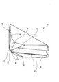
先端インサート230は、図47に示すように、頂点242を有した略三角形状の板状に形成される。先端インサート230は、頂点242から上記三角形の2辺に沿って直線状に延びる2つの切れ刃を有している。該2つの切れ刃は、平面視(図44ではフライス工具200の側面視)において、概ね直線状に延びる第1の切れ刃232aと、頂点242と第1の切れ刃232aとの間に設けられた円弧状の第2の切れ刃232bとを有している。2組の切れ刃232a、232bの各々は、すくい面236と、逃げ面234との交線によって形成される。
本実施形態では、先端インサート230は、固定ねじ212によってヘッド204に固定される。そのため、ヘッド204は、その先端部に切欠き部210を有している。切欠き部210には、固定ねじ212をねじ込むねじ穴(図示せず)が形成されており、先端インサート230は、固定ねじ212の先端形状と類似したくぼみ240が形成されている。
なお、既述の実施形態では、フライス工具10、100、200について、上側インサート20、120、220および下側インサート22、122、222は各々2つ、先端インサート30、50、230は各々1つ備えていたが、本発明は、これに限定されず、上側インサート、下側インサートは、それぞれ少なくとも1つ備えられていればよい。また、上側インサートの主切れ刃、最大径部周辺の副切れ刃、下側インサートの主切れ刃、先端インサートの主切れ刃および先端切れ刃のそれぞれの役割を、複数に分割または統合した切れ刃を備えているインサート式またはソリッド式の工具であってもよい。
10 フライス工具
12 シャンク
14 ヘッド
14a 拡径部
14b 縮径部
14c 遷移部
20 上側インサート
20c 第1の切れ刃
20j 第2の切れ刃
22 下側インサート
22c 第1の切れ刃
22j 第2の切れ刃
30 先端インサート
32a 第1の切れ刃
38 頂点
70 ワーク
72 底壁
74 リブ
76 リターンフランジ
12 シャンク
14 ヘッド
14a 拡径部
14b 縮径部
14c 遷移部
20 上側インサート
20c 第1の切れ刃
20j 第2の切れ刃
22 下側インサート
22c 第1の切れ刃
22j 第2の切れ刃
30 先端インサート
32a 第1の切れ刃
38 頂点
70 ワーク
72 底壁
74 リブ
76 リターンフランジ
Claims (5)
- シャンク部と、該シャンク部の先端側に設けられ、切れ刃を有するヘッドとで構成されたフライス工具において、
前記ヘッドは、前記シャンク部に接する基端部から先端方向に直径が次第に拡大する拡径部と、最大直径部から先端方向に直径が次第に縮小する縮径部とを含み、
前記拡径部および前記縮径部の各々に設けられた少なくとも1つの切れ刃と、
前記ヘッドの先端部において、前記縮径部から前記フライス工具の軸心まで延設された少なくとも1つの先端切れ刃と、
を具備することを特徴としたフライス工具。 - 前記拡径部の切れ刃は、前記拡径部に取り付けられた上側インサートに形成され、前記縮径部の切れ刃は、前記縮径部に取り付けられた下側インサートに形成されており、
前記上側インサートと下側インサートは、各々の一端から直線状に延びる第1の切れ刃を有しており、前記先端インサートは、フライス工具が回転したときに前記下側インサートの第1の切れ刃が描く円錐面に沿う直線状の主切れ刃を有している請求項1に記載のフライス工具。 - 前記上側インサートと下側インサートは、各々の前記第1の切れ刃に接続され前記上側インサートと下側インサートの他端に配置された凸状に湾曲した第2の切れ刃を更に有しており、前記上側インサートと下側インサートは、各々の第2の切れ刃が、前記拡径部と縮径部との接合部に隣接するように配置され、前記先端インサートは、フライス工具が回転したときに前記下側インサートの第1の切れ刃が描く円錐面に沿う直線状の主切れ刃を有している請求項2に記載のフライス工具。
- 前記先端インサートは、先端中央部に前記主切れ刃に接するように接続された円弧状の副切れ刃を更に有している請求項3に記載のフライス工具。
- 工作機械のテーブルに固定されたワークのリブと該リブに続けて形成されるリターンフランジとの内側部分をアンダーカットするワークの加工方法において、請求項1に記載のフライス工具を前記工作機械の主軸に取り付けて回転させ、
前記フライス工具の前記拡径部の切れ刃でリターンフランジの内側を加工し、前記フライス工具の前記縮径部の切れ刃および先端切れ刃でリブの側面およびリターンフランジの内側とリブの側面との間の隅部を加工するワークの加工方法。
Priority Applications (4)
| Application Number | Priority Date | Filing Date | Title |
|---|---|---|---|
| CA3138082A CA3138082C (en) | 2019-04-26 | 2020-04-22 | MILLING TOOL AND METHOD FOR MACHINING A WORKPIECE |
| US17/606,526 US12214430B2 (en) | 2019-04-26 | 2020-04-22 | Milling tool and workpiece machining method |
| CN202080030975.2A CN113747991B (zh) | 2019-04-26 | 2020-04-22 | 铣刀以及工件加工方法 |
| EP20795554.3A EP3960346A4 (en) | 2019-04-26 | 2020-04-22 | MILLING TOOL AND WORKPIECE MACHINING PROCESS |
Applications Claiming Priority (2)
| Application Number | Priority Date | Filing Date | Title |
|---|---|---|---|
| JP2019086565A JP6861755B2 (ja) | 2019-04-26 | 2019-04-26 | フライス工具およびワークの加工方法 |
| JP2019-086565 | 2019-04-26 |
Publications (1)
| Publication Number | Publication Date |
|---|---|
| WO2020218333A1 true WO2020218333A1 (ja) | 2020-10-29 |
Family
ID=72942193
Family Applications (1)
| Application Number | Title | Priority Date | Filing Date |
|---|---|---|---|
| PCT/JP2020/017330 Ceased WO2020218333A1 (ja) | 2019-04-26 | 2020-04-22 | フライス工具およびワークの加工方法 |
Country Status (6)
| Country | Link |
|---|---|
| US (1) | US12214430B2 (ja) |
| EP (1) | EP3960346A4 (ja) |
| JP (1) | JP6861755B2 (ja) |
| CN (1) | CN113747991B (ja) |
| CA (1) | CA3138082C (ja) |
| WO (1) | WO2020218333A1 (ja) |
Families Citing this family (2)
| Publication number | Priority date | Publication date | Assignee | Title |
|---|---|---|---|---|
| CN117399687A (zh) * | 2023-11-10 | 2024-01-16 | 中铁宝桥集团有限公司 | 一种镶嵌翼轨加工组合刀具及其加工方法 |
| HUP2400283A1 (en) * | 2024-05-27 | 2025-11-28 | Budapesti Mueszaki Es Gazdasagtudomanyi Egyetem | Milling tool and related technology for minimizing cutting-induced edge delamination and interlayer burr in multilayer metal/fibre reinforced polymer composite structures |
Citations (4)
| Publication number | Priority date | Publication date | Assignee | Title |
|---|---|---|---|---|
| JPS6285812U (ja) * | 1985-11-19 | 1987-06-01 | ||
| JPH02150111U (ja) * | 1989-05-22 | 1990-12-25 | ||
| JPH04300107A (ja) * | 1991-03-28 | 1992-10-23 | Mitsubishi Materials Corp | チップ取付面の加工方法及び加工工具 |
| WO2014068710A1 (ja) * | 2012-10-31 | 2014-05-08 | 株式会社牧野フライス製作所 | T形カッタ、リブの加工方法及び航空機部品 |
Family Cites Families (64)
| Publication number | Priority date | Publication date | Assignee | Title |
|---|---|---|---|---|
| US1499818A (en) * | 1922-09-27 | 1924-07-01 | Franconetti August | Gem-seat-grooving tool |
| US3283663A (en) * | 1964-10-29 | 1966-11-08 | Charles E Davis | High speed milling apparatus |
| US4032251A (en) * | 1975-05-05 | 1977-06-28 | The Weldon Tool Company | Countersinking and deburring tool |
| US4197042A (en) * | 1977-12-15 | 1980-04-08 | Everede Tool Company | Countersinking tool |
| US4293254A (en) * | 1979-09-17 | 1981-10-06 | Everede Tool Company | Countersinking tool with removable cutting inserts |
| JPS5943049Y2 (ja) * | 1979-11-22 | 1984-12-19 | ダイジヱツト工業株式会社 | T溝フライス |
| US4527643A (en) * | 1983-02-07 | 1985-07-09 | Megadiamond Industries Inc. | Rotary cutting member for drilling holes |
| US4591302A (en) * | 1984-08-22 | 1986-05-27 | Lovendahl Norman H | Countersink with disposable insert |
| US4799834A (en) * | 1985-11-04 | 1989-01-24 | Mcdonnell Douglas | Cutter insert for KEVLAR |
| JPS6295812U (ja) * | 1985-12-03 | 1987-06-18 | ||
| CH672084A5 (ja) * | 1986-10-08 | 1989-10-31 | Starrfraesmaschinen Ag | |
| US4988241A (en) * | 1989-09-15 | 1991-01-29 | The Boeing Company | Cutter with angled diamond inserts |
| GB8925360D0 (en) * | 1989-11-09 | 1989-12-28 | Sandvik Ltd | Milling cutters |
| US5259707A (en) * | 1992-08-17 | 1993-11-09 | Keller Dale L | Spot drill with indexable replaceable insert |
| ES2110019T3 (es) * | 1993-04-14 | 1998-02-01 | Stellram Gmbh | Fresa. |
| IL108659A (en) * | 1994-02-16 | 1997-11-20 | Noga Eng Ltd | Reversible countersink |
| US5478178A (en) * | 1994-06-29 | 1995-12-26 | Valenite Inc. | High speed rotary boring tool |
| US5647699A (en) * | 1995-07-17 | 1997-07-15 | Great Lakes Carbide Tool Manufacturing, Inc. | Rotary cutter head |
| US5893683A (en) * | 1997-04-29 | 1999-04-13 | Ingersoll Cutting Tool Company | Indexable insert router |
| JPH11320232A (ja) * | 1998-05-20 | 1999-11-24 | Toshiba Tungaloy Co Ltd | 面取りカッタ |
| US6149354A (en) * | 1998-12-16 | 2000-11-21 | Walters; Jayce P. | Tool and method for cutting a seat in the setting of stones in jewelry |
| US6095723A (en) * | 1999-01-19 | 2000-08-01 | Nemco Medical | Engraving tool and method for forming |
| JP2000288823A (ja) * | 1999-04-02 | 2000-10-17 | Mitsubishi Materials Corp | スローアウェイ式エンドミル |
| US6220795B1 (en) * | 1999-04-05 | 2001-04-24 | Vermont Indexable Tooling, Inc. | Spotting drill and milling cutter |
| JP3474489B2 (ja) * | 1999-08-30 | 2003-12-08 | 株式会社信栄製作所 | カッター |
| DE19956592A1 (de) * | 1999-11-25 | 2001-06-13 | Sandvik Ab | Kugelbahnfräser und Schneidplatte hierfür |
| IL150783A0 (en) * | 2001-10-16 | 2003-02-12 | Iscar Ltd | Cutting tool and cutting insert therefor |
| US7052214B2 (en) * | 2002-07-02 | 2006-05-30 | Janness Daniel L | Cutting insert and tool holder |
| DE10349334B4 (de) * | 2003-10-23 | 2006-11-02 | Depo Gmbh & Co.Kg. | Einschraubfräser |
| US7287937B2 (en) * | 2004-08-09 | 2007-10-30 | Hsin-Tien Chang | Multi-function milling cutter |
| JP2007276010A (ja) * | 2006-04-03 | 2007-10-25 | Tatsuno Metate Kakosho:Kk | 回転切削工具及びその製造方法 |
| US20080298917A1 (en) * | 2007-06-04 | 2008-12-04 | Hsin-Tien Chang | Disposable Cutter |
| JP5239471B2 (ja) * | 2008-04-11 | 2013-07-17 | 三菱マテリアル株式会社 | プランジ加工用カッタおよびプランジ加工方法 |
| DE102008056682B4 (de) * | 2008-09-03 | 2010-10-28 | Gbz Mannheim Gmbh & Co. Kg | Fräs- und Entgratwerkzeug |
| ITGE20080098A1 (it) * | 2008-11-24 | 2010-05-25 | Delta Tools Srl | Utensile per la lavorazione mediante asportazione di truciolo, con inserti amovibili |
| DE102009011195B4 (de) * | 2009-03-04 | 2016-09-15 | Schneider Gmbh & Co. Kg | Fräskopf für eine Fräsmaschine zum Herstellen von Brillengläsern aus Kunststoff |
| DE102009012670A1 (de) * | 2009-03-13 | 2010-09-16 | Busch & Co. Kg | Doppelkegelfräser |
| US8961077B2 (en) * | 2009-10-26 | 2015-02-24 | Illlinois Tool Works Inc. | Severing and beveling tool |
| KR20120083499A (ko) * | 2009-12-08 | 2012-07-25 | 가부시키가이샤 탕가로이 | 날끝 교환식 절삭공구 |
| DE102010005580A1 (de) * | 2010-01-22 | 2011-07-28 | Gühring OHG, 72458 | Schneidwerkzeug mit kegelstumpfförmigen Schneidelementen |
| JP2011148072A (ja) * | 2010-01-23 | 2011-08-04 | Segawa Tool Service Co Ltd | 切削工具 |
| DE102010000640A1 (de) * | 2010-03-04 | 2011-09-08 | Gühring Ohg | Stirnfräser |
| FR2967086B1 (fr) * | 2010-11-05 | 2013-07-12 | Dassault Aviat | Outil rotatif de percage d'un trou dans une piece mecanique, dispositif et procede de percage associes |
| JP6313287B2 (ja) * | 2013-04-30 | 2018-04-18 | シチズン時計株式会社 | 面取加工方法 |
| JP6247807B2 (ja) * | 2014-12-12 | 2017-12-13 | 株式会社 東陽 | 切削工具及びこの切削工具を備えた切削装置 |
| JP2016190299A (ja) * | 2015-03-31 | 2016-11-10 | 三菱マテリアル株式会社 | 総形エンドミル |
| CN205270981U (zh) * | 2015-12-30 | 2016-06-01 | 东莞市翔通光电技术有限公司 | 一种双面锥形倒角刀 |
| US11351620B2 (en) * | 2016-04-15 | 2022-06-07 | Mapal Fabrik für Praäzisionswerkzeuge Dr. Kress KG | Milling head for a ball track milling cutter, ball track milling cutter having a milling head of this type, method for producing a cutting edge for a ball track milling cutter, computer program product for carrying out a method of this type, data carrier having a computer program product of this type, and grinding machine for carrying out the method |
| JP2016129932A (ja) * | 2016-04-25 | 2016-07-21 | 国立大学法人名古屋大学 | 複合材料成形物のトリミングに用いられるミリング加工工具 |
| CN109641293B (zh) | 2016-08-26 | 2020-10-20 | 三菱日立工具株式会社 | 切削刀片及可转位刀片式旋转切削工具 |
| DE102017214622A1 (de) * | 2017-02-24 | 2018-08-30 | Gühring KG | Kegelsenker |
| CN206882872U (zh) * | 2017-04-17 | 2018-01-16 | 铁科(北京)轨道装备技术有限公司 | 一种轨腰成型用鱼尾槽铣刀 |
| TWI825040B (zh) * | 2017-11-30 | 2023-12-11 | 以色列商艾斯卡公司 | 單側三向可轉位銑削嵌件、刀具固持器及包括嵌件及刀具固持器的嵌件式銑刀 |
| JP6896101B2 (ja) * | 2017-12-13 | 2021-06-30 | 株式会社牧野フライス製作所 | フライス工具及びワークの加工方法 |
| CN110248754B (zh) * | 2018-01-08 | 2021-02-05 | Osg株式会社 | 嵌件以及机体 |
| CN208067391U (zh) * | 2018-03-20 | 2018-11-09 | 德阳杰创科技有限公司 | 一种钻铣复合刀具 |
| CN208230938U (zh) * | 2018-04-18 | 2018-12-14 | 河源龙记金属制品有限公司 | 一种铣刀及具有撬模位的模架 |
| KR102601952B1 (ko) * | 2018-04-18 | 2023-11-14 | 가네후사 가부시키가이샤 | 딤플이 형성된 피가공물 및 딤플 가공 방법 |
| DE102018119927A1 (de) * | 2018-08-16 | 2020-02-20 | Hartmetall-Werkzeugfabrik Paul Horn Gmbh | Faswerkzeug |
| DE102019202458B4 (de) * | 2019-02-22 | 2021-10-14 | Glen Dimplex Deutschland Gmbh | Verfahren zur Instandhaltung eines Ventils, Ventilfräser und Verwendung eines Ventilfräsers |
| PL3708282T3 (pl) * | 2019-03-14 | 2022-09-12 | Haertel Meiko | Narzędzie pierścieniowe do obróbki przedmiotu obrabianego |
| KR102840280B1 (ko) * | 2019-05-20 | 2025-07-30 | 이스카 엘티디. | 고속-이송 선삭 공구 어셈블리 |
| DE102019214041A1 (de) * | 2019-09-16 | 2021-03-18 | Gühring KG | Fräswerkzeug |
| US11731204B2 (en) * | 2020-10-19 | 2023-08-22 | Iscar, Ltd. | High-feed milling tool |
-
2019
- 2019-04-26 JP JP2019086565A patent/JP6861755B2/ja active Active
-
2020
- 2020-04-22 US US17/606,526 patent/US12214430B2/en active Active
- 2020-04-22 WO PCT/JP2020/017330 patent/WO2020218333A1/ja not_active Ceased
- 2020-04-22 CA CA3138082A patent/CA3138082C/en active Active
- 2020-04-22 EP EP20795554.3A patent/EP3960346A4/en active Pending
- 2020-04-22 CN CN202080030975.2A patent/CN113747991B/zh active Active
Patent Citations (4)
| Publication number | Priority date | Publication date | Assignee | Title |
|---|---|---|---|---|
| JPS6285812U (ja) * | 1985-11-19 | 1987-06-01 | ||
| JPH02150111U (ja) * | 1989-05-22 | 1990-12-25 | ||
| JPH04300107A (ja) * | 1991-03-28 | 1992-10-23 | Mitsubishi Materials Corp | チップ取付面の加工方法及び加工工具 |
| WO2014068710A1 (ja) * | 2012-10-31 | 2014-05-08 | 株式会社牧野フライス製作所 | T形カッタ、リブの加工方法及び航空機部品 |
Non-Patent Citations (1)
| Title |
|---|
| See also references of EP3960346A4 * |
Also Published As
| Publication number | Publication date |
|---|---|
| EP3960346A4 (en) | 2023-01-25 |
| CN113747991A (zh) | 2021-12-03 |
| US20220203462A1 (en) | 2022-06-30 |
| EP3960346A1 (en) | 2022-03-02 |
| JP2020182981A (ja) | 2020-11-12 |
| US12214430B2 (en) | 2025-02-04 |
| CN113747991B (zh) | 2024-10-01 |
| CA3138082A1 (en) | 2020-10-29 |
| JP6861755B2 (ja) | 2021-04-21 |
| CA3138082C (en) | 2024-10-15 |
Similar Documents
| Publication | Publication Date | Title |
|---|---|---|
| JP5620929B2 (ja) | 切削インサートおよび切削工具、並びにそれを用いた切削加工物の製造方法 | |
| US11014174B2 (en) | Multi-flute end mill | |
| JP6817717B2 (ja) | フライスカッタ、切削インサート及びフライス加工方法 | |
| CN1980762A (zh) | 用于高速铣刀的切削刀片 | |
| JP2004517739A (ja) | フライス用スローアウェイチップインサート | |
| JPH11254218A (ja) | 穴加工を主体とする複合切刃工具及び加工方法 | |
| JP6896101B2 (ja) | フライス工具及びワークの加工方法 | |
| JP2008279547A (ja) | 溝加工方法および総形回転切削工具 | |
| US20200406362A1 (en) | Turning method for a cnc-lathe | |
| CN109641293B (zh) | 切削刀片及可转位刀片式旋转切削工具 | |
| JP6861755B2 (ja) | フライス工具およびワークの加工方法 | |
| JP6226114B2 (ja) | ねじ切りフライス及びそれを用いた管用めねじ加工方法 | |
| JPWO2020245878A1 (ja) | ボールエンドミル及び切削インサート | |
| JP7527796B2 (ja) | 多刃ボールエンドミル及び多刃ボールエンドミルの加工方法 | |
| JPH10128610A (ja) | 穴加工を主体とする複合切刃工具及び加工方法 | |
| JPH11156620A (ja) | 円弧刃エンドミル | |
| JPH064205B2 (ja) | 穴明け加工方法 | |
| JP2008207332A (ja) | 切削方法 | |
| CN113399727A (zh) | 一种面铣精加工刀具 | |
| JP2007245338A (ja) | ミリングカッタ | |
| JP2023552898A (ja) | 金属切削旋削工具 | |
| JP3823226B2 (ja) | 切削工具 | |
| JP2001198718A (ja) | 曲面切削法 | |
| JPH1190722A (ja) | ラジアス刃エンドミル | |
| JPS6337137Y2 (ja) |
Legal Events
| Date | Code | Title | Description |
|---|---|---|---|
| 121 | Ep: the epo has been informed by wipo that ep was designated in this application |
Ref document number: 20795554 Country of ref document: EP Kind code of ref document: A1 |
|
| ENP | Entry into the national phase |
Ref document number: 3138082 Country of ref document: CA |
|
| NENP | Non-entry into the national phase |
Ref country code: DE |
|
| ENP | Entry into the national phase |
Ref document number: 2020795554 Country of ref document: EP Effective date: 20211126 |