WO2020235421A1 - Dispositif de sécurité de gaz - Google Patents
Dispositif de sécurité de gaz Download PDFInfo
- Publication number
- WO2020235421A1 WO2020235421A1 PCT/JP2020/019150 JP2020019150W WO2020235421A1 WO 2020235421 A1 WO2020235421 A1 WO 2020235421A1 JP 2020019150 W JP2020019150 W JP 2020019150W WO 2020235421 A1 WO2020235421 A1 WO 2020235421A1
- Authority
- WO
- WIPO (PCT)
- Prior art keywords
- pressure
- gas
- flow rate
- unit
- pressure sensor
- Prior art date
- Legal status (The legal status is an assumption and is not a legal conclusion. Google has not performed a legal analysis and makes no representation as to the accuracy of the status listed.)
- Ceased
Links
Images




Classifications
-
- G—PHYSICS
- G01—MEASURING; TESTING
- G01F—MEASURING VOLUME, VOLUME FLOW, MASS FLOW OR LIQUID LEVEL; METERING BY VOLUME
- G01F1/00—Measuring the volume flow or mass flow of fluid or fluent solid material wherein the fluid passes through a meter in a continuous flow
- G01F1/66—Measuring the volume flow or mass flow of fluid or fluent solid material wherein the fluid passes through a meter in a continuous flow by measuring frequency, phase shift or propagation time of electromagnetic or other waves, e.g. using ultrasonic flowmeters
-
- G—PHYSICS
- G01—MEASURING; TESTING
- G01F—MEASURING VOLUME, VOLUME FLOW, MASS FLOW OR LIQUID LEVEL; METERING BY VOLUME
- G01F3/00—Measuring the volume flow of fluids or fluent solid material wherein the fluid passes through the meter in successive and more or less isolated quantities, the meter being driven by the flow
- G01F3/02—Measuring the volume flow of fluids or fluent solid material wherein the fluid passes through the meter in successive and more or less isolated quantities, the meter being driven by the flow with measuring chambers which expand or contract during measurement
- G01F3/20—Measuring the volume flow of fluids or fluent solid material wherein the fluid passes through the meter in successive and more or less isolated quantities, the meter being driven by the flow with measuring chambers which expand or contract during measurement having flexible movable walls, e.g. diaphragms, bellows
- G01F3/22—Measuring the volume flow of fluids or fluent solid material wherein the fluid passes through the meter in successive and more or less isolated quantities, the meter being driven by the flow with measuring chambers which expand or contract during measurement having flexible movable walls, e.g. diaphragms, bellows for gases
-
- G—PHYSICS
- G01—MEASURING; TESTING
- G01L—MEASURING FORCE, STRESS, TORQUE, WORK, MECHANICAL POWER, MECHANICAL EFFICIENCY, OR FLUID PRESSURE
- G01L15/00—Devices or apparatus for measuring two or more fluid pressure values simultaneously
Definitions
- the present disclosure relates to a gas security device that measures a gas flow rate and shuts off a gas passage when an abnormal flow rate is measured to ensure safety in using gas.
- This gas security device includes an ultrasonic sensor, an ultrasonic flow rate measuring unit in which a circuit board including an ultrasonic sensor drive circuit is integrated, and a pressure sensor that measures a differential pressure between supply pressure and atmospheric pressure. Further, when it is determined that the differential pressure between the supply pressure and the atmospheric pressure measured by the pressure sensor is abnormal, it has a control function of shutting off the flow path to stop the gas supply and a function of notifying.
- the pressure sensor built into the gas security device is a differential pressure measurement type that measures the pressure of gas with the atmospheric pressure as a reference, it has a through hole for introducing gas into the pressure sensor, and the area around the gas security device is very large. If the temperature becomes too high, gas may leak from the through hole. Therefore, as a configuration that does not require a through hole, there is a configuration in which the change in gas supply pressure is measured from the difference between the measured values of the absolute pressure pressure sensor that measures the atmospheric pressure and the absolute pressure pressure sensor that measures the gas pressure.
- the gas security device in the present disclosure is arranged inside a flow path for flowing gas, a flow rate measuring unit for measuring the flow rate of gas flowing through the flow path, and a second, and measures the absolute pressure of gas. It includes a pressure sensor of 1 and a second pressure sensor arranged outside the flow path and measuring the absolute pressure of atmospheric pressure. In addition, a pressure value collecting unit that collects n pressure values measured by the first pressure sensor and m pressure values measured by the second pressure sensor, and a pressure value collecting unit that collects m pressure values, respectively. It is provided with a gas pressure determination unit that calculates the gas supply pressure from the difference between the average values of the pressure values.
- shutoff valve that shuts off the flow path and the flow rate measuring unit are controlled, and when an abnormality is determined from the flow rate measured by the flow rate measuring section and the gas supply pressure calculated by the gas pressure determination section, the flow path is cut off by the shutoff valve.
- a control circuit for shutting off is provided.
- the gas supply pressure can be accurately measured in a gas security device in which gas does not eject even when the temperature around the gas security device becomes high.
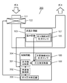
- FIG. 1 is a configuration diagram of a gas security device according to the first embodiment.
- FIG. 2 is an operation explanatory view of the gas security device according to the first embodiment.
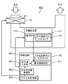
- FIG. 3 is a block diagram of the gas security device according to the second embodiment.
- FIG. 4 is an operation explanatory view of the gas security device according to the second embodiment.
- FIG. 5 is a block diagram of the gas security device according to the third embodiment.
- FIG. 6 is an operation explanatory view of the gas security device according to the third embodiment.
- FIG. 7 is a block diagram of the gas security device according to the fourth embodiment.
- FIG. 8 is an operation explanatory view of the gas security device according to the fourth embodiment.
- the gas safety device 100 includes a flow path 101 through which gas flows, a shutoff valve 102 that shuts off the flow path 101, a flow rate measuring unit 103 that measures the flow rate of gas flowing through the flow path 101, and a flow rate measuring unit 103.
- a control circuit 104 that integrates the amount of gas used using the flow rate measurement data measured in 1 is provided.
- the gas safety device 100 includes a gas side absolute pressure pressure sensor 105 which is a first pressure sensor for measuring the absolute pressure of gas, and an atmospheric side absolute pressure pressure which is a second pressure sensor for measuring the absolute pressure of the atmosphere.
- a value collecting unit 108 is provided.
- the gas security device 100 includes a gas pressure determination unit 109 that calculates the average value of each pressure value collected by the pressure value collection unit 108 and calculates the gas supply pressure from the difference.
- the gas-side absolute pressure pressure sensor 105 is mounted as an electronic component on the electronic circuit 107 installed in the gas atmosphere inside the flow path 101, and the gas inside the flow path 101 is received by a signal from the control circuit 104. Measure the absolute pressure of. Further, the atmospheric side absolute pressure pressure sensor 106 is mounted as an electronic component on a control circuit 104 installed in the atmosphere outside the flow path 101, and measures the absolute pressure of the atmosphere with a signal from the control circuit 104. To do.
- the pressure measurement by the gas pressure determination unit 109 is periodically executed at a predetermined time interval T (for example, 2 to 10 seconds).
- T a predetermined time interval
- the pressure measurement times T1 and T2 indicate the timing of the pressure measurement.
- n pressure values of the absolute pressure of the gas are collected by the pressure value sampling unit 108, and the absolute pressure of the atmosphere is measured. M pressure values are collected.
- the pressure values Pg (1), Pg (2), ... Pg (n) are set at predetermined intervals (for example, 5 ms) by the gas side absolute pressure pressure sensor 105, which is the first pressure sensor. -1), a total of n (for example, 32) pressure values of Pg (n) are measured and collected by the pressure value collecting unit 108.
- the pressure values Pa (1), Pa (2), ... Pa () are used at predetermined intervals (for example, 5 ms) by the atmospheric side absolute pressure pressure sensor 106 which is the second pressure sensor.
- a total of m (for example, 32) pressure values of m-1) and Pa (m) are measured and collected by the pressure value collecting unit 108.
- the gas pressure determination unit 109 determines the difference (Pg-Pa) between the gas pressure value Pg obtained by averaging the n gas pressure values and the atmospheric pressure value Pa obtained by averaging the atmospheric pressure values m. Calculated as gas supply pressure.
- the control circuit 104 determines the flow rate measurement data measured by the flow rate measurement unit 103, the gas supply pressure calculated by the gas pressure determination unit 109, and its change, determines whether or not there is an abnormality such as a gas leak, and determines that the abnormality is present. If this happens, the shutoff valve 102 shuts off the flow path 101 to stop the gas supply.
- the n pressure values measured by the gas side absolute pressure pressure sensor 105 which is the first pressure sensor capable of measuring the absolute pressure
- the second pressure capable of measuring the absolute pressure
- Fluctuations in the gas supply pressure are detected using the average value of m pressure values measured by the atmospheric side absolute pressure pressure sensor 106, which is a sensor. Therefore, the measurement accuracy can be improved due to the individual variation of the first pressure sensor and the second pressure sensor and the error of the measurement timing, and the through hole required when using the differential pressure measurement type pressure sensor becomes unnecessary. Therefore, it is possible to prevent gas from being ejected even when the temperature around the gas security device becomes high, and a gas security device with higher safety can be realized.
- the flow rate measuring unit even if the flow rate measuring unit is used for ultrasonic flow rate measurement, it can operate in the same manner.
- the number of measured gas pressure values (n) and the number of measured atmospheric pressure values (m) are the same 32, but depending on the measurement environment such as the influence of pressure fluctuation and noise. The number may be different. Alternatively, the number of measured absolute pressures (m) of the atmosphere, which is expected to have little fluctuation, may be less than the number of measured absolute pressures of gas (n). In this case, the second pressure sensor The power consumption by a certain atmospheric side absolute pressure pressure sensor 106 can be reduced.
- the gas side absolute pressure sensor 105 which is the first pressure sensor, has been described as a configuration in which the gas side absolute pressure sensor 105 is mounted on the electronic circuit 107 installed in the gas atmosphere inside the flow path 101. Needless to say, it may be mounted anywhere in the flow path. Further, although the configuration has been described in which the atmospheric side absolute pressure pressure sensor 106 is mounted on the control circuit 104 installed in the atmosphere outside the flow path 101, there is no limitation on the mounting location as long as the atmospheric pressure can be measured.
- the gas safety device 200 includes a flow path 101 through which gas flows, a shutoff valve 102 that shuts off the flow path 101, a flow rate measuring unit 103 that measures the flow rate of gas flowing through the flow path 101, and a flow rate measuring unit 103. It is provided with a control circuit 204 for integrating the amount of gas used using the flow rate measurement data measured in. Further, the gas safety device 200 includes a gas-side absolute pressure pressure sensor 105, which is a first pressure sensor for measuring the absolute pressure of gas, and an atmospheric-side absolute pressure pressure, which is a second pressure sensor for measuring the absolute pressure of the atmosphere. It includes a sensor 106 and an electronic circuit 107 installed in a gas atmosphere.
- the gas safety device 200 collects n differential pressure values measured at the same timing by the gas side absolute pressure pressure sensor 105 and the atmospheric side absolute pressure pressure sensor 106 at a predetermined measurement time.
- a unit 201 and a gas pressure determination unit 209 that calculates a gas supply pressure from the average value of n differential pressure values collected by the differential pressure value collecting unit 201 are provided.
- the pressure measurement by the gas pressure determination unit 209 is periodically executed at a predetermined time interval T (for example, 2 to 10 seconds).
- T for example, 2 to 10 seconds.
- the pressure measurement times T1 and T2 indicate the timing of the pressure measurement, and at the pressure measurement time T1, the pressure value of the absolute pressure of the gas and the pressure value of the absolute pressure of the atmosphere are set by the differential pressure value sampling unit 201. N differential pressure values are collected.
- the difference from the first embodiment is that the difference between the gas pressure value and the atmospheric pressure value measured at the same timing by the gas side absolute pressure pressure sensor 105 and the atmospheric side absolute pressure pressure sensor 106 is measured by the pressure value sampling unit 108. It is a point to collect n pieces at.
- the pressure values Pg (1), Pg (2), ... Pg (1), ... Pg (2), ... Pg (1), Pg (2), ... Pg (1), Pg (2), ... A total of n pressure values of n-1) and Pg (n) are measured.
- the atmospheric side absolute pressure pressure sensor 106 which is the second pressure sensor, the pressure values Pa (1), Pa (2) ... Pa (n ⁇ ) at the same timing as each measurement by the gas side absolute pressure pressure sensor 105. 1), Pa (n), a total of n pressure values (for example, 32 pressure values) are measured.
- the gas pressure determination unit 209 calculates the gas supply pressure by averaging n difference values.
- the control circuit 204 determines the flow rate measurement data measured by the flow rate measurement unit 103, the gas supply pressure calculated by the gas pressure determination unit 209, and its change, determines whether or not there is an abnormality such as a gas leak, and determines that the abnormality is present. If this happens, the shutoff valve 102 shuts off the flow path 101 to stop the gas supply.
- the gas side absolute pressure pressure sensor 105 which is the first pressure sensor
- the atmospheric side absolute pressure pressure sensor 106 which is the second pressure sensor
- the gas side absolute pressure sensor 105 can measure the absolute pressure at the same timing. Fluctuations in gas supply pressure are detected using the average value of the difference between the measured pressure values. Therefore, the measurement accuracy can be improved due to the individual variation of the first pressure sensor and the second pressure sensor and the error of the measurement timing, and the through hole required when using the differential pressure measurement type pressure sensor becomes unnecessary. Therefore, it is possible to prevent gas from being ejected even when the temperature around the gas security device becomes high, and a gas security device with higher safety can be realized.
- FIG. 5 the same components described with reference to FIG. 1 are indicated by the same reference numerals.
- the gas safety device 300 includes a flow path 101 through which gas flows, a shutoff valve 102 that shuts off the flow path 101, a flow rate measuring unit 103 that measures the flow rate of gas flowing through the flow path 101, and a flow rate measuring unit 103.
- the control circuit 304 which integrates the amount of gas used by using the flow rate measurement data measured in 1.
- the gas safety device 300 includes a gas-side absolute pressure pressure sensor 105, which is a first pressure sensor for measuring the absolute pressure of gas, and an atmospheric-side absolute pressure pressure, which is a second pressure sensor for measuring the absolute pressure of the atmosphere. It includes a sensor 106 and an electronic circuit 107 installed in a gas atmosphere.
- the gas safety device 300 has a pressure value sampling unit 108 that collects predetermined pressure values measured by the gas side absolute pressure pressure sensor 105 and the atmosphere side absolute pressure pressure sensor 106 at an arbitrary measurement time, and a pressure value.
- a comparison unit 301, an abnormal value ignoring unit 302, and a gas pressure determination unit 309 are provided.
- the pressure value comparison unit 301 compares each pressure value obtained by the pressure value collection unit 108.
- the outlier ignoring unit 302 determines that the value determined by the pressure value comparing unit 301 to be clearly different from the other pressure values is an outlier. In that judgment, for example, three consecutive pressure measurements are compared and one measurement is more than 1000 pascals different from the other, or that measurement is relative to the overall average. If there is a difference of more than a predetermined ratio, the measured value is determined to be an abnormal value. Based on this determination, the pressure value excluding the abnormal value is output to the gas pressure determination unit 309.
- the gas pressure determination unit 309 calculates the average value of each of the gas pressure value and the atmospheric pressure value output from the abnormal value ignoring unit 302, and calculates the difference between the average values as the gas supply pressure.
- the pressure measurement by the gas pressure determination unit 309 is periodically executed at a predetermined time interval T (for example, 2 seconds to 10 seconds).
- T the pressure measurement times T1 and T2 indicate the timing of pressure measurement.
- n absolute pressures of gas are measured by the gas side absolute pressure pressure sensor 105, and the atmospheric side absolute pressure pressure sensor
- the absolute pressure of m is measured by 106, and n gas pressure values and m atmospheric pressure values are collected by the pressure value collecting unit 108.
- the pressure values Pg (1), Pg (2), ... Pg (n-1), Pg () are measured at predetermined intervals (for example, 5 ms) by the gas side absolute pressure pressure sensor 105.
- a total of n (for example, 32) pressure values of n) are measured.
- the atmospheric side absolute pressure pressure sensor 106 a total of m pressure values Pa (1), Pa (2), ... Pa (m-1), Pa (m) are provided at predetermined intervals (for example, 5 ms). Pressure values (for example, 32) are measured.
- the second pressure value Pg (2) of the gas is clearly different from the other measured values and is determined by the pressure value comparing unit 301 to be an abnormal value by comparison with the other measured values.
- Perform the following processing That is, at the gas pressure measurement time T1, n-1 pressure values excluding the second pressure value Pg (2) are output to the gas pressure determination unit 309 in the abnormal value ignoring unit 302, and the gas is averaged.
- the pressure value Pg of is calculated.
- m pressure values are output to the gas pressure determination unit 309, and the gas pressure determination unit 309 averages the m pressure values to the atmospheric pressure value. Pa is calculated.
- the gas pressure determination unit 309 has the gas side pressure value Pg obtained by averaging the n-1 pressure values excluding the abnormal pressure value Pg (2) and m of the atmospheric side absolute pressure.
- the difference (Pg-Pa) of the atmospheric pressure value Pa obtained by averaging the pressure values is calculated as the gas supply pressure.
- the control circuit 304 determines the flow rate measurement data measured by the flow rate measurement unit 103, the gas supply pressure calculated by the gas pressure determination unit 309, and its change, determines whether there is an abnormality such as a gas leak, and determines that the abnormality is present. If this happens, the shutoff valve 102 shuts off the flow path 101 to stop the gas supply.
- the gas is used by using the gas side absolute pressure pressure sensor 105 which is the first pressure sensor capable of measuring the absolute pressure and the atmospheric side absolute pressure pressure sensor 106 which is the second pressure sensor.
- the gas side absolute pressure pressure sensor 105 which is the first pressure sensor capable of measuring the absolute pressure
- the atmospheric side absolute pressure pressure sensor 106 which is the second pressure sensor.
- FIG. 7 the same components described with reference to FIGS. 1 and 3 are indicated by the same numbers.
- the gas safety device 400 includes a flow path 101 through which gas flows, a shutoff valve 102 that shuts off the flow path 101, a flow rate measuring unit 103 that measures the flow rate of gas flowing through the flow path 101, and a flow rate measuring unit 103.
- a control circuit 404 that integrates the amount of gas used using the flow rate measurement data measured in 1 is provided.
- the gas safety device 400 includes a gas-side absolute pressure pressure sensor 105, which is a first pressure sensor for measuring the absolute pressure of gas, and an atmospheric-side absolute pressure pressure, which is a second pressure sensor for measuring the absolute pressure of the atmosphere. It includes a sensor 106 and an electronic circuit 107 installed in a gas atmosphere.
- the gas safety device 400 is a differential pressure value collecting unit that collects n differences of pressure values measured at the same timing by the gas side absolute pressure pressure sensor 105 and the atmospheric side absolute pressure pressure sensor 106 at a predetermined measurement time. It includes 201, a differential pressure value comparison unit 401, a differential pressure abnormal value ignoring unit 402, and a gas pressure determination unit 409.
- the differential pressure value comparison unit 401 compares the n differential pressure values obtained by the differential pressure value collection unit 201.
- the differential pressure abnormal value ignoring unit 402 determines in the differential pressure value comparison unit 401 that the value is clearly different from the other differential pressure values as an abnormal value. In that judgment, for example, the differential pressure values of three consecutive pressure values are compared, and one of them has a difference of 1000 pascals or more from the other differential pressure values, or a predetermined ratio or more with respect to the overall average. If there is a difference, the differential pressure value is determined to be an abnormal value.
- the n-1 differential pressure values excluding this abnormal value are output to the gas pressure determination unit 409.
- the gas pressure determination unit 409 calculates the average value of n-1 differential pressure values output from the differential pressure value comparison unit 401 and calculates it as the gas supply pressure.
- the pressure measurement by the gas pressure determination unit 209 is periodically executed at a predetermined time interval T (for example, 2 seconds to 10 seconds).
- T for example, 2 seconds to 10 seconds.
- the pressure measurement times T1 and T2 indicate the timing of the pressure measurement, and at the pressure measurement time T1, the pressure value of the absolute pressure of the gas and the pressure value of the absolute pressure of the atmosphere are set by the differential pressure value sampling unit 201. N differential pressure values are collected.
- the pressure values Pg (1), Pg (2), ... Pg (1), Pg (2), ... Pg (for example, 5 ms) by the gas side absolute pressure pressure sensor 105 which is the first pressure sensor.
- a total of n (for example, 32) pressure values of n-1) and Pg (n) are measured.
- the second pressure value Pg (2) on the gas side is clearly different from the other measured values, and the differential pressure value ⁇ P (2) calculated by Pg (2) and Pa (2) is
- the differential pressure value comparison unit 401 determines that the value is abnormal by comparing with another value, the following processing is performed. That is, in the gas pressure measurement time T1, the gas pressure determination is performed by n-1 differential pressure values excluding the second differential pressure value ⁇ P (2) determined to be an abnormal value in the differential pressure abnormal value ignoring unit 402. It is output to the unit 409, and the gas pressure determination unit 409 calculates the average value of n-1 differential pressure values as the gas supply pressure.
- the control circuit 404 determines the flow rate measurement data measured by the flow rate measurement unit 103, the gas supply pressure calculated by the gas pressure determination unit 409, and its change, determines whether there is an abnormality such as a gas leak, and determines that the abnormality is present. If this happens, the shutoff valve 102 shuts off the flow path 101 to stop the gas supply.
- the gas side absolute pressure pressure sensor 105 which is the first pressure sensor capable of measuring the absolute pressure and the atmospheric side absolute pressure pressure sensor 106 which is the second pressure sensor are used and the same.
- the gas supply pressure is calculated by excluding abnormally measured values from the differential pressure values of the pressure values measured at the timing.
- a flow path for flowing a gas a flow rate measuring unit for measuring the flow rate of the gas flowing through the flow path, and an absolute pressure of the gas arranged inside the flow path are measured. It includes a first pressure sensor for measuring and a second pressure sensor arranged outside the flow path for measuring the absolute pressure of atmospheric pressure.
- a pressure value collecting unit that collects n pressure values measured by the first pressure sensor and m pressure values measured by the second pressure sensor, and a pressure value collecting unit that collects m pressure values, respectively. It is provided with a gas pressure determination unit that calculates the gas supply pressure from the difference between the average values of the pressure values.
- shutoff valve that shuts off the flow path and the flow rate measuring unit are controlled, and when an abnormality is determined from the flow rate measured by the flow rate measuring section and the gas supply pressure calculated by the gas pressure determination section, the flow path is cut off by the shutoff valve.
- a control circuit for shutting off is provided.
- the gas supply pressure is detected using the average value of the first pressure sensor and the second pressure sensor that measure the absolute pressure, so that the individual variation and measurement of the first pressure sensor and the second pressure sensor are performed.
- the measurement accuracy can be improved due to the timing error, and the through hole required when using the differential pressure measurement type pressure sensor becomes unnecessary. Therefore, it is possible to prevent gas from being ejected even when the temperature around the gas security device becomes high, and a gas security device with higher safety can be realized.
- the second disclosure particularly in the first disclosure, includes an average value comparison unit that compares the pressure values and average values of the first pressure sensor and the second pressure sensor collected by the pressure value collection unit. Further, the gas pressure determination unit may be configured to calculate the average value by excluding the pressure value determined to be clearly different from the average value among the pressure values collected by the pressure value collection unit value in the average value comparison unit. Good.
- the gas supply pressure is detected using the average value of the pressure values measured by the first pressure sensor and the second pressure sensor, respectively, so that individual variations of the first pressure sensor and the second pressure sensor may occur.
- the measurement accuracy can be improved due to the error in the measurement timing, and the through hole required when using the differential pressure measurement type pressure sensor becomes unnecessary. Therefore, it is possible to prevent gas from being ejected even when the temperature around the gas security device becomes high, and a gas security device with higher safety can be realized.
- a third disclosure particularly in any one of the first or second disclosures, is that the flow rate measuring unit has a measuring circuit arranged inside the flow path, and the first pressure sensor is configured on the measuring circuit.
- the control circuit may be arranged outside the flow path and the second pressure sensor may be arranged on the control circuit.
- the flow rate measuring unit includes an ultrasonic flow rate measuring unit that integrates an ultrasonic sensor and a measuring circuit that drives the ultrasonic sensor to measure the flow rate, and the ultrasonic flow rate.
- the ultrasonic flow measuring unit is provided with a first pressure sensor, and by controlling the ultrasonic flow measuring unit with a control circuit, the first pressure sensor can also be controlled. Good.
- the fifth disclosure is a flow path for flowing a gas, a flow rate measuring unit for measuring the flow rate of the gas flowing through the flow path, and a first pressure arranged inside the flow path for measuring the absolute pressure of the gas. It includes a sensor and a second pressure sensor that is arranged outside the flow path and measures the absolute pressure of atmospheric pressure.
- a differential pressure value collecting unit that collects n differential pressure values of the pressure values measured by the second pressure sensor at the same timing as the pressure value measured by the first pressure sensor and the measurement of the first pressure sensor.
- a gas pressure determination unit that calculates the gas supply pressure based on the average value of n differential pressure values collected by the differential pressure value collection unit is provided.
- shutoff valve that shuts off the flow path and the flow rate measuring unit are controlled, and when an abnormality is determined from the flow rate measured by the flow rate measuring section and the gas supply pressure calculated by the gas pressure determination section, the flow path is cut off by the shutoff valve.
- a control circuit for shutting off is provided.
- the sixth disclosure particularly in the fifth disclosure, includes a differential pressure value comparison unit that compares the differential pressure values collected by the differential pressure value collection unit, and the gas pressure determination unit makes a difference in the differential pressure value comparison unit.
- the average value may be calculated by excluding the differential pressure value determined to be clearly different from the other differential pressure values among the differential pressure values collected by the pressure value collecting unit.
- the flow rate measuring unit has a measuring circuit arranged inside the flow path, and the first pressure sensor is configured on the measuring circuit.
- the control circuit may be arranged outside the flow path, and the second pressure sensor may be arranged on the control circuit.
- the flow rate measuring unit includes an ultrasonic flow rate measuring unit that integrates an ultrasonic sensor and a measuring circuit that drives the ultrasonic sensor to measure the flow rate, and the ultrasonic flow rate.
- the ultrasonic flow measuring unit is provided with a first pressure sensor, and by controlling the ultrasonic flow measuring unit with a control circuit, the first pressure sensor can also be controlled. Good.
- the gas security device can prevent gas from being ejected from the through hole for the pressure sensor even when the temperature around the gas security device becomes high, so that not only the safety can be improved but also the gas is cheaper.
- a security device can be realized, and it can be applied to applications such as general household and commercial gas meters.
Landscapes
- Physics & Mathematics (AREA)
- General Physics & Mathematics (AREA)
- Fluid Mechanics (AREA)
- Measuring Volume Flow (AREA)
- Electromagnetism (AREA)
Abstract
La présente invention est pourvue : d'un canal d'écoulement (101) ; d'une unité de mesure de débit (103) qui mesure le débit d'un gaz qui s'écoule à travers le canal d'écoulement (101) ; d'un capteur de pression de pression absolue côté gaz (105) qui mesure la pression absolue d'un gaz ; et d'un capteur de pression de pression absolue côté atmosphère (106) qui mesure la pression absolue d'une pression atmosphérique. De plus, la présente invention est pourvue : d'une unité de collecte de valeur de pression (108) qui collecte un nombre prédéterminé de valeurs de pression mesurées par chacun du capteur de pression de pression absolue côté gaz (105) et du capteur de pression de pression absolue côté atmosphère (106) durant une période de mesure prédéterminée ; et d'une unité de détermination de pression de gaz (109) qui calcule une pression à partir d'une différence entre des valeurs moyennes collectées par l'unité de collecte de valeur de pression (108). En outre, la présente invention est pourvue d'une soupape d'arrêt (102) qui ferme le canal d'écoulement (101) ; et d'un circuit de commande (104) qui commande l'unité de mesure de débit (103) et qui, lorsqu'il est déterminé que le débit mesuré par l'unité de mesure de débit (103) ou un changement de pression mesuré par l'unité de détermination de pression de gaz (109) est anormal, ferme le canal d'écoulement (101) avec la soupape d'arrêt (102).
Applications Claiming Priority (2)
| Application Number | Priority Date | Filing Date | Title |
|---|---|---|---|
| JP2019-093461 | 2019-05-17 | ||
| JP2019093461A JP2020187081A (ja) | 2019-05-17 | 2019-05-17 | ガス保安装置 |
Publications (1)
| Publication Number | Publication Date |
|---|---|
| WO2020235421A1 true WO2020235421A1 (fr) | 2020-11-26 |
Family
ID=73221716
Family Applications (1)
| Application Number | Title | Priority Date | Filing Date |
|---|---|---|---|
| PCT/JP2020/019150 Ceased WO2020235421A1 (fr) | 2019-05-17 | 2020-05-13 | Dispositif de sécurité de gaz |
Country Status (2)
| Country | Link |
|---|---|
| JP (2) | JP2020187081A (fr) |
| WO (1) | WO2020235421A1 (fr) |
Families Citing this family (1)
| Publication number | Priority date | Publication date | Assignee | Title |
|---|---|---|---|---|
| US11815388B2 (en) * | 2020-12-01 | 2023-11-14 | Honeywell International Inc. | Method and system for timely detecting gas pressure irregularities using a gas meter in a power efficient manner |
Citations (9)
| Publication number | Priority date | Publication date | Assignee | Title |
|---|---|---|---|---|
| JPH06180373A (ja) * | 1992-12-11 | 1994-06-28 | Jeco Co Ltd | 晴雨計 |
| JPH0777584A (ja) * | 1993-09-08 | 1995-03-20 | Seikosha Co Ltd | 気圧検出方法 |
| JP2006520901A (ja) * | 2003-03-21 | 2006-09-14 | ローズマウント インコーポレイテッド | バスによってゲージ圧力計算回路に接続された絶対圧力センサおよび大気圧センサを有する圧力測定装置 |
| JP2014098563A (ja) * | 2012-11-13 | 2014-05-29 | Panasonic Corp | 流量計測装置 |
| JP2015145826A (ja) * | 2014-02-03 | 2015-08-13 | 矢崎エナジーシステム株式会社 | ガスメータ |
| JP2015145827A (ja) * | 2014-02-03 | 2015-08-13 | 矢崎エナジーシステム株式会社 | 計測流路ユニット |
| JP2018169299A (ja) * | 2017-03-30 | 2018-11-01 | 富士通株式会社 | 液位測定システム、液位測定方法、及び液位測定プログラム |
| JP2019502435A (ja) * | 2015-12-02 | 2019-01-31 | フィッシャー アンド ペイケル ヘルスケア リミテッド | フロー療法装置用の流路検知 |
| JP2019066347A (ja) * | 2017-10-02 | 2019-04-25 | 横河電機株式会社 | 計測システム、制御システム及び計測方法 |
Family Cites Families (8)
| Publication number | Priority date | Publication date | Assignee | Title |
|---|---|---|---|---|
| JPS61140842A (ja) * | 1984-12-14 | 1986-06-27 | Kawasaki Steel Corp | 流動状態の金属、絶縁物の連続分析装置 |
| JPS61156399A (ja) * | 1984-12-27 | 1986-07-16 | 富士電機株式会社 | デジタルフイルタ方式 |
| JP3376470B2 (ja) * | 1997-07-18 | 2003-02-10 | 矢崎総業株式会社 | ガス遮断弁付ガスメータ |
| JP3620012B2 (ja) * | 1999-04-09 | 2005-02-16 | 矢崎総業株式会社 | ガス供給圧異常検出装置及び電子式ガスメータ |
| JP2005233437A (ja) * | 2004-02-17 | 2005-09-02 | Tokyo Gas Co Ltd | 圧力異常検知装置および圧力異常検知方法 |
| JP2008014813A (ja) * | 2006-07-06 | 2008-01-24 | Taiyo Nippon Sanso Corp | 真空度測定装置、気相成長装置および真空度測定方法 |
| WO2018031403A1 (fr) * | 2016-08-08 | 2018-02-15 | 3M Innovative Properties Company | Détection de l'état d'un filtre à air |
| US11857262B2 (en) * | 2017-09-29 | 2024-01-02 | Glaukos Corporation | Intraocular physiological sensor |
-
2019
- 2019-05-17 JP JP2019093461A patent/JP2020187081A/ja active Pending
-
2020
- 2020-05-13 WO PCT/JP2020/019150 patent/WO2020235421A1/fr not_active Ceased
-
2023
- 2023-06-05 JP JP2023092097A patent/JP2023101797A/ja active Pending
Patent Citations (9)
| Publication number | Priority date | Publication date | Assignee | Title |
|---|---|---|---|---|
| JPH06180373A (ja) * | 1992-12-11 | 1994-06-28 | Jeco Co Ltd | 晴雨計 |
| JPH0777584A (ja) * | 1993-09-08 | 1995-03-20 | Seikosha Co Ltd | 気圧検出方法 |
| JP2006520901A (ja) * | 2003-03-21 | 2006-09-14 | ローズマウント インコーポレイテッド | バスによってゲージ圧力計算回路に接続された絶対圧力センサおよび大気圧センサを有する圧力測定装置 |
| JP2014098563A (ja) * | 2012-11-13 | 2014-05-29 | Panasonic Corp | 流量計測装置 |
| JP2015145826A (ja) * | 2014-02-03 | 2015-08-13 | 矢崎エナジーシステム株式会社 | ガスメータ |
| JP2015145827A (ja) * | 2014-02-03 | 2015-08-13 | 矢崎エナジーシステム株式会社 | 計測流路ユニット |
| JP2019502435A (ja) * | 2015-12-02 | 2019-01-31 | フィッシャー アンド ペイケル ヘルスケア リミテッド | フロー療法装置用の流路検知 |
| JP2018169299A (ja) * | 2017-03-30 | 2018-11-01 | 富士通株式会社 | 液位測定システム、液位測定方法、及び液位測定プログラム |
| JP2019066347A (ja) * | 2017-10-02 | 2019-04-25 | 横河電機株式会社 | 計測システム、制御システム及び計測方法 |
Also Published As
| Publication number | Publication date |
|---|---|
| JP2020187081A (ja) | 2020-11-19 |
| JP2023101797A (ja) | 2023-07-21 |
Similar Documents
| Publication | Publication Date | Title |
|---|---|---|
| EP2805136B1 (fr) | Système pour surveiller en temps réel un débit au travers de régulateurs de débit massique | |
| US8800383B2 (en) | Flow monitored particle sensor | |
| DE60232506D1 (de) | Strömungsmessung | |
| EP3105647B1 (fr) | Système et procédé permettant de produire un régulateur de débit massique autocontrôlé insensible à la pression | |
| EP3779376B1 (fr) | Dispositif de sécurité pour le gaz | |
| US9046222B2 (en) | Flowmeter | |
| JP2000120918A (ja) | 弁装置 | |
| EP3805712B1 (fr) | Dispositif de sécurité de gaz | |
| WO2020235421A1 (fr) | Dispositif de sécurité de gaz | |
| JP7426600B2 (ja) | ガス保安装置 | |
| US20250198817A1 (en) | High sensitivity ultrasonic flow meter | |
| US20140278184A1 (en) | Zero Deadband Processing for Velocity Transmitters | |
| JP2005267572A (ja) | 流量制御の異常判定方法及び装置 | |
| JP4083367B2 (ja) | ガス保安装置 | |
| JP4832906B2 (ja) | 流量計 | |
| JP4019419B2 (ja) | 導圧管詰まり検出器およびそれを内蔵した差圧・圧力伝送器 | |
| JP7249594B2 (ja) | ガス保安装置、及び、ガス保安システム | |
| JP2000193506A (ja) | ガス保安装置 | |
| JP2997576B2 (ja) | フルイディックガスメータにおける漏洩検査用単位流量信号出力方法 |
Legal Events
| Date | Code | Title | Description |
|---|---|---|---|
| 121 | Ep: the epo has been informed by wipo that ep was designated in this application |
Ref document number: 20808696 Country of ref document: EP Kind code of ref document: A1 |
|
| NENP | Non-entry into the national phase |
Ref country code: DE |
|
| 122 | Ep: pct application non-entry in european phase |
Ref document number: 20808696 Country of ref document: EP Kind code of ref document: A1 |