WO2020235484A1 - プリプレグ、積層体および成形品 - Google Patents
プリプレグ、積層体および成形品 Download PDFInfo
- Publication number
- WO2020235484A1 WO2020235484A1 PCT/JP2020/019466 JP2020019466W WO2020235484A1 WO 2020235484 A1 WO2020235484 A1 WO 2020235484A1 JP 2020019466 W JP2020019466 W JP 2020019466W WO 2020235484 A1 WO2020235484 A1 WO 2020235484A1
- Authority
- WO
- WIPO (PCT)
- Prior art keywords
- resin
- component
- prepreg
- laminate
- mpa
- Prior art date
- Legal status (The legal status is an assumption and is not a legal conclusion. Google has not performed a legal analysis and makes no representation as to the accuracy of the status listed.)
- Ceased
Links
Images

Classifications
-
- C—CHEMISTRY; METALLURGY
- C08—ORGANIC MACROMOLECULAR COMPOUNDS; THEIR PREPARATION OR CHEMICAL WORKING-UP; COMPOSITIONS BASED THEREON
- C08J—WORKING-UP; GENERAL PROCESSES OF COMPOUNDING; AFTER-TREATMENT NOT COVERED BY SUBCLASSES C08B, C08C, C08F, C08G or C08H
- C08J5/00—Manufacture of articles or shaped materials containing macromolecular substances
- C08J5/24—Impregnating materials with prepolymers which can be polymerised in situ, e.g. manufacture of prepregs
- C08J5/241—Impregnating materials with prepolymers which can be polymerised in situ, e.g. manufacture of prepregs using inorganic fibres
- C08J5/243—Impregnating materials with prepolymers which can be polymerised in situ, e.g. manufacture of prepregs using inorganic fibres using carbon fibres
-
- B—PERFORMING OPERATIONS; TRANSPORTING
- B29—WORKING OF PLASTICS; WORKING OF SUBSTANCES IN A PLASTIC STATE IN GENERAL
- B29C—SHAPING OR JOINING OF PLASTICS; SHAPING OF MATERIAL IN A PLASTIC STATE, NOT OTHERWISE PROVIDED FOR; AFTER-TREATMENT OF THE SHAPED PRODUCTS, e.g. REPAIRING
- B29C70/00—Shaping composites, i.e. plastics material comprising reinforcements, fillers or preformed parts, e.g. inserts
- B29C70/003—Shaping composites, i.e. plastics material comprising reinforcements, fillers or preformed parts, e.g. inserts characterised by the matrix material, e.g. material composition or physical properties
- B29C70/0035—Shaping composites, i.e. plastics material comprising reinforcements, fillers or preformed parts, e.g. inserts characterised by the matrix material, e.g. material composition or physical properties comprising two or more matrix materials
-
- B—PERFORMING OPERATIONS; TRANSPORTING
- B29—WORKING OF PLASTICS; WORKING OF SUBSTANCES IN A PLASTIC STATE IN GENERAL
- B29C—SHAPING OR JOINING OF PLASTICS; SHAPING OF MATERIAL IN A PLASTIC STATE, NOT OTHERWISE PROVIDED FOR; AFTER-TREATMENT OF THE SHAPED PRODUCTS, e.g. REPAIRING
- B29C70/00—Shaping composites, i.e. plastics material comprising reinforcements, fillers or preformed parts, e.g. inserts
- B29C70/04—Shaping composites, i.e. plastics material comprising reinforcements, fillers or preformed parts, e.g. inserts comprising reinforcements only, e.g. self-reinforcing plastics
- B29C70/06—Fibrous reinforcements only
- B29C70/10—Fibrous reinforcements only characterised by the structure of fibrous reinforcements, e.g. hollow fibres
- B29C70/16—Fibrous reinforcements only characterised by the structure of fibrous reinforcements, e.g. hollow fibres using fibres of substantial or continuous length
- B29C70/18—Fibrous reinforcements only characterised by the structure of fibrous reinforcements, e.g. hollow fibres using fibres of substantial or continuous length in the form of a mat, e.g. sheet moulding compound [SMC]
-
- B—PERFORMING OPERATIONS; TRANSPORTING
- B29—WORKING OF PLASTICS; WORKING OF SUBSTANCES IN A PLASTIC STATE IN GENERAL
- B29C—SHAPING OR JOINING OF PLASTICS; SHAPING OF MATERIAL IN A PLASTIC STATE, NOT OTHERWISE PROVIDED FOR; AFTER-TREATMENT OF THE SHAPED PRODUCTS, e.g. REPAIRING
- B29C70/00—Shaping composites, i.e. plastics material comprising reinforcements, fillers or preformed parts, e.g. inserts
- B29C70/88—Shaping composites, i.e. plastics material comprising reinforcements, fillers or preformed parts, e.g. inserts characterised primarily by possessing specific properties, e.g. electrically conductive or locally reinforced
-
- B—PERFORMING OPERATIONS; TRANSPORTING
- B32—LAYERED PRODUCTS
- B32B—LAYERED PRODUCTS, i.e. PRODUCTS BUILT-UP OF STRATA OF FLAT OR NON-FLAT, e.g. CELLULAR OR HONEYCOMB, FORM
- B32B3/00—Layered products comprising a layer with external or internal discontinuities or unevennesses, or a layer of non-planar shape; Layered products comprising a layer having particular features of form
- B32B3/02—Layered products comprising a layer with external or internal discontinuities or unevennesses, or a layer of non-planar shape; Layered products comprising a layer having particular features of form characterised by features of form at particular places, e.g. in edge regions
- B32B3/08—Layered products comprising a layer with external or internal discontinuities or unevennesses, or a layer of non-planar shape; Layered products comprising a layer having particular features of form characterised by features of form at particular places, e.g. in edge regions characterised by added members at particular parts
-
- B—PERFORMING OPERATIONS; TRANSPORTING
- B32—LAYERED PRODUCTS
- B32B—LAYERED PRODUCTS, i.e. PRODUCTS BUILT-UP OF STRATA OF FLAT OR NON-FLAT, e.g. CELLULAR OR HONEYCOMB, FORM
- B32B5/00—Layered products characterised by the non- homogeneity or physical structure, i.e. comprising a fibrous, filamentary, particulate or foam layer; Layered products characterised by having a layer differing constitutionally or physically in different parts
- B32B5/02—Layered products characterised by the non- homogeneity or physical structure, i.e. comprising a fibrous, filamentary, particulate or foam layer; Layered products characterised by having a layer differing constitutionally or physically in different parts characterised by structural features of a fibrous or filamentary layer
-
- B—PERFORMING OPERATIONS; TRANSPORTING
- B32—LAYERED PRODUCTS
- B32B—LAYERED PRODUCTS, i.e. PRODUCTS BUILT-UP OF STRATA OF FLAT OR NON-FLAT, e.g. CELLULAR OR HONEYCOMB, FORM
- B32B5/00—Layered products characterised by the non- homogeneity or physical structure, i.e. comprising a fibrous, filamentary, particulate or foam layer; Layered products characterised by having a layer differing constitutionally or physically in different parts
- B32B5/22—Layered products characterised by the non- homogeneity or physical structure, i.e. comprising a fibrous, filamentary, particulate or foam layer; Layered products characterised by having a layer differing constitutionally or physically in different parts characterised by the presence of two or more layers which are next to each other and are fibrous, filamentary, formed of particles or foamed
- B32B5/24—Layered products characterised by the non- homogeneity or physical structure, i.e. comprising a fibrous, filamentary, particulate or foam layer; Layered products characterised by having a layer differing constitutionally or physically in different parts characterised by the presence of two or more layers which are next to each other and are fibrous, filamentary, formed of particles or foamed one layer being a fibrous or filamentary layer
- B32B5/26—Layered products characterised by the non- homogeneity or physical structure, i.e. comprising a fibrous, filamentary, particulate or foam layer; Layered products characterised by having a layer differing constitutionally or physically in different parts characterised by the presence of two or more layers which are next to each other and are fibrous, filamentary, formed of particles or foamed one layer being a fibrous or filamentary layer another layer next to it also being fibrous or filamentary
-
- B—PERFORMING OPERATIONS; TRANSPORTING
- B29—WORKING OF PLASTICS; WORKING OF SUBSTANCES IN A PLASTIC STATE IN GENERAL
- B29K—INDEXING SCHEME ASSOCIATED WITH SUBCLASSES B29B, B29C OR B29D, RELATING TO MOULDING MATERIALS OR TO MATERIALS FOR MOULDS, REINFORCEMENTS, FILLERS OR PREFORMED PARTS, e.g. INSERTS
- B29K2063/00—Use of EP, i.e. epoxy resins or derivatives thereof, as moulding material
-
- B—PERFORMING OPERATIONS; TRANSPORTING
- B29—WORKING OF PLASTICS; WORKING OF SUBSTANCES IN A PLASTIC STATE IN GENERAL
- B29K—INDEXING SCHEME ASSOCIATED WITH SUBCLASSES B29B, B29C OR B29D, RELATING TO MOULDING MATERIALS OR TO MATERIALS FOR MOULDS, REINFORCEMENTS, FILLERS OR PREFORMED PARTS, e.g. INSERTS
- B29K2101/00—Use of unspecified macromolecular compounds as moulding material
- B29K2101/12—Thermoplastic materials
-
- B—PERFORMING OPERATIONS; TRANSPORTING
- B29—WORKING OF PLASTICS; WORKING OF SUBSTANCES IN A PLASTIC STATE IN GENERAL
- B29K—INDEXING SCHEME ASSOCIATED WITH SUBCLASSES B29B, B29C OR B29D, RELATING TO MOULDING MATERIALS OR TO MATERIALS FOR MOULDS, REINFORCEMENTS, FILLERS OR PREFORMED PARTS, e.g. INSERTS
- B29K2105/00—Condition, form or state of moulded material or of the material to be shaped
- B29K2105/06—Condition, form or state of moulded material or of the material to be shaped containing reinforcements, fillers or inserts
- B29K2105/08—Condition, form or state of moulded material or of the material to be shaped containing reinforcements, fillers or inserts of continuous length, e.g. cords, rovings, mats, fabrics, strands or yarns
- B29K2105/0872—Prepregs
-
- B—PERFORMING OPERATIONS; TRANSPORTING
- B29—WORKING OF PLASTICS; WORKING OF SUBSTANCES IN A PLASTIC STATE IN GENERAL
- B29K—INDEXING SCHEME ASSOCIATED WITH SUBCLASSES B29B, B29C OR B29D, RELATING TO MOULDING MATERIALS OR TO MATERIALS FOR MOULDS, REINFORCEMENTS, FILLERS OR PREFORMED PARTS, e.g. INSERTS
- B29K2307/00—Use of elements other than metals as reinforcement
- B29K2307/04—Carbon
-
- B—PERFORMING OPERATIONS; TRANSPORTING
- B29—WORKING OF PLASTICS; WORKING OF SUBSTANCES IN A PLASTIC STATE IN GENERAL
- B29K—INDEXING SCHEME ASSOCIATED WITH SUBCLASSES B29B, B29C OR B29D, RELATING TO MOULDING MATERIALS OR TO MATERIALS FOR MOULDS, REINFORCEMENTS, FILLERS OR PREFORMED PARTS, e.g. INSERTS
- B29K2995/00—Properties of moulding materials, reinforcements, fillers, preformed parts or moulds
- B29K2995/0037—Other properties
- B29K2995/0046—Elastic
-
- B—PERFORMING OPERATIONS; TRANSPORTING
- B29—WORKING OF PLASTICS; WORKING OF SUBSTANCES IN A PLASTIC STATE IN GENERAL
- B29K—INDEXING SCHEME ASSOCIATED WITH SUBCLASSES B29B, B29C OR B29D, RELATING TO MOULDING MATERIALS OR TO MATERIALS FOR MOULDS, REINFORCEMENTS, FILLERS OR PREFORMED PARTS, e.g. INSERTS
- B29K2995/00—Properties of moulding materials, reinforcements, fillers, preformed parts or moulds
- B29K2995/0037—Other properties
- B29K2995/0072—Roughness, e.g. anti-slip
-
- B—PERFORMING OPERATIONS; TRANSPORTING
- B29—WORKING OF PLASTICS; WORKING OF SUBSTANCES IN A PLASTIC STATE IN GENERAL
- B29K—INDEXING SCHEME ASSOCIATED WITH SUBCLASSES B29B, B29C OR B29D, RELATING TO MOULDING MATERIALS OR TO MATERIALS FOR MOULDS, REINFORCEMENTS, FILLERS OR PREFORMED PARTS, e.g. INSERTS
- B29K2995/00—Properties of moulding materials, reinforcements, fillers, preformed parts or moulds
- B29K2995/0037—Other properties
- B29K2995/0077—Yield strength; Tensile strength
-
- B—PERFORMING OPERATIONS; TRANSPORTING
- B29—WORKING OF PLASTICS; WORKING OF SUBSTANCES IN A PLASTIC STATE IN GENERAL
- B29K—INDEXING SCHEME ASSOCIATED WITH SUBCLASSES B29B, B29C OR B29D, RELATING TO MOULDING MATERIALS OR TO MATERIALS FOR MOULDS, REINFORCEMENTS, FILLERS OR PREFORMED PARTS, e.g. INSERTS
- B29K2995/00—Properties of moulding materials, reinforcements, fillers, preformed parts or moulds
- B29K2995/0037—Other properties
- B29K2995/0082—Flexural strength; Flexion stiffness
-
- B—PERFORMING OPERATIONS; TRANSPORTING
- B32—LAYERED PRODUCTS
- B32B—LAYERED PRODUCTS, i.e. PRODUCTS BUILT-UP OF STRATA OF FLAT OR NON-FLAT, e.g. CELLULAR OR HONEYCOMB, FORM
- B32B2250/00—Layers arrangement
- B32B2250/20—All layers being fibrous or filamentary
-
- B—PERFORMING OPERATIONS; TRANSPORTING
- B32—LAYERED PRODUCTS
- B32B—LAYERED PRODUCTS, i.e. PRODUCTS BUILT-UP OF STRATA OF FLAT OR NON-FLAT, e.g. CELLULAR OR HONEYCOMB, FORM
- B32B2250/00—Layers arrangement
- B32B2250/40—Symmetrical or sandwich layers, e.g. ABA, ABCBA, ABCCBA
-
- B—PERFORMING OPERATIONS; TRANSPORTING
- B32—LAYERED PRODUCTS
- B32B—LAYERED PRODUCTS, i.e. PRODUCTS BUILT-UP OF STRATA OF FLAT OR NON-FLAT, e.g. CELLULAR OR HONEYCOMB, FORM
- B32B2260/00—Layered product comprising an impregnated, embedded, or bonded layer wherein the layer comprises an impregnation, embedding, or binder material
- B32B2260/02—Composition of the impregnated, bonded or embedded layer
- B32B2260/021—Fibrous or filamentary layer
- B32B2260/023—Two or more layers
-
- B—PERFORMING OPERATIONS; TRANSPORTING
- B32—LAYERED PRODUCTS
- B32B—LAYERED PRODUCTS, i.e. PRODUCTS BUILT-UP OF STRATA OF FLAT OR NON-FLAT, e.g. CELLULAR OR HONEYCOMB, FORM
- B32B2260/00—Layered product comprising an impregnated, embedded, or bonded layer wherein the layer comprises an impregnation, embedding, or binder material
- B32B2260/04—Impregnation, embedding, or binder material
- B32B2260/046—Synthetic resin
-
- B—PERFORMING OPERATIONS; TRANSPORTING
- B32—LAYERED PRODUCTS
- B32B—LAYERED PRODUCTS, i.e. PRODUCTS BUILT-UP OF STRATA OF FLAT OR NON-FLAT, e.g. CELLULAR OR HONEYCOMB, FORM
- B32B2262/00—Composition or structural features of fibres which form a fibrous or filamentary layer or are present as additives
- B32B2262/10—Inorganic fibres
- B32B2262/106—Carbon fibres, e.g. graphite fibres
-
- B—PERFORMING OPERATIONS; TRANSPORTING
- B32—LAYERED PRODUCTS
- B32B—LAYERED PRODUCTS, i.e. PRODUCTS BUILT-UP OF STRATA OF FLAT OR NON-FLAT, e.g. CELLULAR OR HONEYCOMB, FORM
- B32B2307/00—Properties of the layers or laminate
- B32B2307/30—Properties of the layers or laminate having particular thermal properties
- B32B2307/306—Resistant to heat
-
- B—PERFORMING OPERATIONS; TRANSPORTING
- B32—LAYERED PRODUCTS
- B32B—LAYERED PRODUCTS, i.e. PRODUCTS BUILT-UP OF STRATA OF FLAT OR NON-FLAT, e.g. CELLULAR OR HONEYCOMB, FORM
- B32B2307/00—Properties of the layers or laminate
- B32B2307/50—Properties of the layers or laminate having particular mechanical properties
- B32B2307/538—Roughness
-
- B—PERFORMING OPERATIONS; TRANSPORTING
- B32—LAYERED PRODUCTS
- B32B—LAYERED PRODUCTS, i.e. PRODUCTS BUILT-UP OF STRATA OF FLAT OR NON-FLAT, e.g. CELLULAR OR HONEYCOMB, FORM
- B32B2307/00—Properties of the layers or laminate
- B32B2307/50—Properties of the layers or laminate having particular mechanical properties
- B32B2307/54—Yield strength; Tensile strength
-
- B—PERFORMING OPERATIONS; TRANSPORTING
- B32—LAYERED PRODUCTS
- B32B—LAYERED PRODUCTS, i.e. PRODUCTS BUILT-UP OF STRATA OF FLAT OR NON-FLAT, e.g. CELLULAR OR HONEYCOMB, FORM
- B32B2307/00—Properties of the layers or laminate
- B32B2307/50—Properties of the layers or laminate having particular mechanical properties
- B32B2307/542—Shear strength
-
- B—PERFORMING OPERATIONS; TRANSPORTING
- B32—LAYERED PRODUCTS
- B32B—LAYERED PRODUCTS, i.e. PRODUCTS BUILT-UP OF STRATA OF FLAT OR NON-FLAT, e.g. CELLULAR OR HONEYCOMB, FORM
- B32B2307/00—Properties of the layers or laminate
- B32B2307/50—Properties of the layers or laminate having particular mechanical properties
- B32B2307/546—Flexural strength; Flexion stiffness
-
- B—PERFORMING OPERATIONS; TRANSPORTING
- B32—LAYERED PRODUCTS
- B32B—LAYERED PRODUCTS, i.e. PRODUCTS BUILT-UP OF STRATA OF FLAT OR NON-FLAT, e.g. CELLULAR OR HONEYCOMB, FORM
- B32B2307/00—Properties of the layers or laminate
- B32B2307/50—Properties of the layers or laminate having particular mechanical properties
- B32B2307/558—Impact strength, toughness
-
- B—PERFORMING OPERATIONS; TRANSPORTING
- B32—LAYERED PRODUCTS
- B32B—LAYERED PRODUCTS, i.e. PRODUCTS BUILT-UP OF STRATA OF FLAT OR NON-FLAT, e.g. CELLULAR OR HONEYCOMB, FORM
- B32B2307/00—Properties of the layers or laminate
- B32B2307/70—Other properties
- B32B2307/714—Inert, i.e. inert to chemical degradation, corrosion
-
- B—PERFORMING OPERATIONS; TRANSPORTING
- B32—LAYERED PRODUCTS
- B32B—LAYERED PRODUCTS, i.e. PRODUCTS BUILT-UP OF STRATA OF FLAT OR NON-FLAT, e.g. CELLULAR OR HONEYCOMB, FORM
- B32B2457/00—Electrical equipment
-
- B—PERFORMING OPERATIONS; TRANSPORTING
- B32—LAYERED PRODUCTS
- B32B—LAYERED PRODUCTS, i.e. PRODUCTS BUILT-UP OF STRATA OF FLAT OR NON-FLAT, e.g. CELLULAR OR HONEYCOMB, FORM
- B32B2603/00—Vanes, blades, propellers, rotors with blades
-
- B—PERFORMING OPERATIONS; TRANSPORTING
- B32—LAYERED PRODUCTS
- B32B—LAYERED PRODUCTS, i.e. PRODUCTS BUILT-UP OF STRATA OF FLAT OR NON-FLAT, e.g. CELLULAR OR HONEYCOMB, FORM
- B32B2605/00—Vehicles
- B32B2605/08—Cars
-
- B—PERFORMING OPERATIONS; TRANSPORTING
- B32—LAYERED PRODUCTS
- B32B—LAYERED PRODUCTS, i.e. PRODUCTS BUILT-UP OF STRATA OF FLAT OR NON-FLAT, e.g. CELLULAR OR HONEYCOMB, FORM
- B32B2605/00—Vehicles
- B32B2605/18—Aircraft
-
- C—CHEMISTRY; METALLURGY
- C08—ORGANIC MACROMOLECULAR COMPOUNDS; THEIR PREPARATION OR CHEMICAL WORKING-UP; COMPOSITIONS BASED THEREON
- C08J—WORKING-UP; GENERAL PROCESSES OF COMPOUNDING; AFTER-TREATMENT NOT COVERED BY SUBCLASSES C08B, C08C, C08F, C08G or C08H
- C08J2363/00—Characterised by the use of epoxy resins; Derivatives of epoxy resins
-
- C—CHEMISTRY; METALLURGY
- C08—ORGANIC MACROMOLECULAR COMPOUNDS; THEIR PREPARATION OR CHEMICAL WORKING-UP; COMPOSITIONS BASED THEREON
- C08J—WORKING-UP; GENERAL PROCESSES OF COMPOUNDING; AFTER-TREATMENT NOT COVERED BY SUBCLASSES C08B, C08C, C08F, C08G or C08H
- C08J2365/00—Characterised by the use of macromolecular compounds obtained by reactions forming a carbon-to-carbon link in the main chain; Derivatives of such polymers
-
- C—CHEMISTRY; METALLURGY
- C08—ORGANIC MACROMOLECULAR COMPOUNDS; THEIR PREPARATION OR CHEMICAL WORKING-UP; COMPOSITIONS BASED THEREON
- C08J—WORKING-UP; GENERAL PROCESSES OF COMPOUNDING; AFTER-TREATMENT NOT COVERED BY SUBCLASSES C08B, C08C, C08F, C08G or C08H
- C08J2371/00—Characterised by the use of polyethers obtained by reactions forming an ether link in the main chain; Derivatives of such polymers
-
- C—CHEMISTRY; METALLURGY
- C08—ORGANIC MACROMOLECULAR COMPOUNDS; THEIR PREPARATION OR CHEMICAL WORKING-UP; COMPOSITIONS BASED THEREON
- C08J—WORKING-UP; GENERAL PROCESSES OF COMPOUNDING; AFTER-TREATMENT NOT COVERED BY SUBCLASSES C08B, C08C, C08F, C08G or C08H
- C08J2377/00—Characterised by the use of polyamides obtained by reactions forming a carboxylic amide link in the main chain; Derivatives of such polymers
- C08J2377/02—Polyamides derived from omega-amino carboxylic acids or from lactams thereof
-
- C—CHEMISTRY; METALLURGY
- C08—ORGANIC MACROMOLECULAR COMPOUNDS; THEIR PREPARATION OR CHEMICAL WORKING-UP; COMPOSITIONS BASED THEREON
- C08J—WORKING-UP; GENERAL PROCESSES OF COMPOUNDING; AFTER-TREATMENT NOT COVERED BY SUBCLASSES C08B, C08C, C08F, C08G or C08H
- C08J2379/00—Characterised by the use of macromolecular compounds obtained by reactions forming in the main chain of the macromolecule a linkage containing nitrogen with or without oxygen, or carbon only, not provided for in groups C08J2361/00 - C08J2377/00
- C08J2379/04—Polycondensates having nitrogen-containing heterocyclic rings in the main chain; Polyhydrazides; Polyamide acids or similar polyimide precursors
- C08J2379/08—Polyimides; Polyester-imides; Polyamide-imides; Polyamide acids or similar polyimide precursors
-
- C—CHEMISTRY; METALLURGY
- C08—ORGANIC MACROMOLECULAR COMPOUNDS; THEIR PREPARATION OR CHEMICAL WORKING-UP; COMPOSITIONS BASED THEREON
- C08J—WORKING-UP; GENERAL PROCESSES OF COMPOUNDING; AFTER-TREATMENT NOT COVERED BY SUBCLASSES C08B, C08C, C08F, C08G or C08H
- C08J2381/00—Characterised by the use of macromolecular compounds obtained by reactions forming in the main chain of the macromolecule a linkage containing sulfur with or without nitrogen, oxygen, or carbon only; Polysulfones; Derivatives of such polymers
- C08J2381/04—Polysulfides
Definitions
- the present invention relates to a prepreg containing reinforcing fibers, a thermosetting resin and a thermoplastic resin, a laminate containing a reinforcing fiber, a thermoplastic resin and a cured product of a thermosetting resin, and a molded product.
- Fiber-reinforced composite materials that use thermosetting resin or thermoplastic resin as a matrix and combine them with reinforcing fibers such as carbon fiber and glass fiber are lightweight, yet have mechanical properties such as strength and rigidity, heat resistance, and corrosion resistance. Due to its superiority, it has been applied in many fields such as aerospace, automobiles, railroad vehicles, ships, civil engineering and construction and sporting goods. However, these fiber-reinforced composite materials are not suitable for manufacturing parts and structures having complicated shapes in a single molding process, and in the above application, a member made of the fiber-reinforced composite material is produced. Then it is necessary to integrate with the same or different members.
- a mechanical joining method such as bolts, rivets, and screws, or a joining method using an adhesive is used.
- the mechanical joining method requires a process of pre-processing the joint part such as drilling, it leads to a long manufacturing process and an increase in manufacturing cost, and there is a problem that the material strength is lowered due to drilling. there were.
- the joining method using an adhesive requires a bonding process and a curing process including preparation of the adhesive and application of the adhesive, which leads to a long manufacturing process and sufficient reliability in terms of adhesive strength. There was a problem that I could't get enough satisfaction.
- thermoplastic resin for the fiber-reinforced composite material using a thermoplastic resin as a matrix
- a method of joining members by welding can be applied, so that joining between members can be applied. It may be possible to reduce the time required for.
- heat resistance and resistance are higher than those of fiber-reinforced composite materials composed of thermosetting resins and reinforcing fibers. There was a problem that the chemical properties were not sufficient.
- Patent Document 1 discloses a method of joining a fiber-reinforced composite material composed of a thermosetting resin and a reinforcing fiber via an adhesive.
- Patent Document 2 discloses a method of integrating a member formed of a thermoplastic resin and a member formed of a fiber-reinforced composite material made of a thermosetting resin. That is, a thermoplastic resin film is laminated on the surface of a prepreg sheet made of a reinforcing fiber and a thermosetting resin, and a fiber-reinforced composite material is obtained by heating and pressurizing. Then, the obtained fiber-reinforced composite material is placed in a mold, the thermoplastic resin is injection-molded, and the thermoplastic resin member formed by the injection molding is joined to the fiber-reinforced composite material.
- Patent Document 3 discloses a method for producing a laminate in which a thermoplastic resin adhesive layer is formed on the surface of a composite material composed of a thermosetting resin and a reinforcing fiber, and another method is described via the thermoplastic resin. It is stated that it exhibits an adhesive effect with members.
- Patent Document 4 discloses a prepreg made of a thermoplastic resin, a fiber, or a film arranged on the surface layer of a prepreg made of a reinforcing fiber and a thermosetting resin, and a fiber-reinforced composite material thereof.
- Japanese Unexamined Patent Publication No. 2018-161801 Japanese Unexamined Patent Publication No. 10-138354 Japanese Patent No. 3906319 Japanese Unexamined Patent Publication No. 8-259713
- Patent Document 1 is a method of joining fiber-reinforced composite materials made of reinforcing fibers and a thermosetting resin to each other with an adhesive, and since the thermosetting resin is a matrix resin, the fiber is reinforced as it is. Welding cannot be applied as a method of joining composite materials. Since it takes time to cure the adhesive, there is a problem that the bonding process requires time, and further, the developed bonding strength is not sufficient.
- the fiber-reinforced composite material according to Patent Document 3 can be integrated by welding via a thermoplastic resin, and exhibits excellent bonding strength at room temperature, but the bonding strength at high temperature is not sufficient.
- Patent Document 4 shows that particles, fibers or films made of a thermoplastic resin improve the interlaminar fracture toughness value.
- the thermosetting resin and the thermoplastic resin in the fiber-reinforced composite material are used. The joint strength at the boundary with and was not sufficient.
- an object of the present invention is that it can be bonded to members of the same type or different types by welding, exhibits excellent bonding strength, particularly excellent bonding strength in a high temperature environment, and is also excellent in compressive strength and interlayer fracture toughness. It is an object of the present invention to provide a prepreg, a laminate, and an integrally molded product that provide a laminate suitable as a structural material.
- the prepreg of the present invention has the following configuration.
- the laminate of the present invention is a laminate having the following configuration.
- a layer containing the following components [A], [C] and [D] is included, and [D] has a rubber state elastic modulus of 10 MPa or more at a temperature obtained by adding 50 ° C. to the glass transition temperature.
- the prepreg of the present invention uses a thermosetting resin and a thermoplastic resin, and both are firmly bonded to each other and can be well welded to members of the same type or different types.
- a thermosetting resin and a thermoplastic resin For a fiber-reinforced composite material composed of a resin and a reinforcing fiber, the time required for the joining process can be shortened, and the molding of the structural member can be speeded up. Further, by having an excellent elastic modulus in a rubber state at a predetermined temperature, excellent compressive strength and bonding strength in a high temperature environment can be exhibited, and an excellent laminated body as a structural material can be obtained.
- the laminate of the present invention exhibits excellent performance as a structure by being applied to aircraft structural members, wind turbine blades, automobile structural members, and computer applications such as IC trays and laptop housings.
- the prepreg of the present invention it is possible to significantly reduce the molding time and molding cost of the product according to the above application.
- Examples of the reinforcing fiber of the component [A] used in the present invention include glass fiber, carbon fiber, metal fiber, aromatic polyamide fiber, polyaramid fiber, alumina fiber, silicon carbide fiber, boron fiber, and genbuiwa fiber. These may be used alone or in combination of two or more as appropriate. These reinforcing fibers may be surface-treated. Surface treatments include metal adhesion treatments, coupling agent treatments, sizing agent treatments, and additive adhesion treatments. Among these reinforcing fibers, reinforcing fibers having conductivity are also included. As the reinforcing fiber, carbon fiber is preferably used because it has a small specific gravity, high strength, and a high elastic modulus.
- the form and arrangement of the reinforcing fibers can be appropriately selected from the unidirectional arrangement of the reinforcing fibers, the laminate of the unidirectionally arranged fibers, the form of the woven fabric, etc., but it is lightweight and has a higher level of durability.
- the reinforcing fibers are arranged in one direction in the form of long fibers (fiber bundles) or continuous fibers such as woven fabrics in each prepreg.
- the reinforcing fiber bundle may be composed of a plurality of fibers having the same form, or may be composed of a plurality of fibers having different forms.
- the number of reinforcing fibers constituting one reinforcing fiber bundle is usually 300 to 60,000, but in consideration of the production of the base material, it is preferably 300 to 48,000, and more preferably 1,000. It is ⁇ 24,000.
- the range may be a combination of any of the above upper limits and any of the lower limits.
- the strand tensile strength of the reinforcing fiber of the component [A] measured according to the resin impregnated strand test method of JIS R7608 (2007) is 5.5 GPa or more, it has excellent bonding strength in addition to the tensile strength. It is preferable because a laminated body can be obtained. It is more preferable that the strand tensile strength is 5.8 GPa.
- the joint strength referred to here refers to a tensile shear joint strength obtained in accordance with ISO4587: 1995 (JIS K6850 (1994)).
- the component [B] used in the present invention is a thermosetting resin having a rubber state elastic modulus of 10 MPa or more at a temperature obtained by adding 50 ° C. to the glass transition temperature in a state where the degree of curing is 90% or more.
- the thermosetting resin of the component [B] and the thermosetting resin composition before curing specified as a curing agent are subjected to predetermined conditions. This can be achieved by heat curing.
- the heat curing under predetermined conditions means that first, heating is performed at 135 ° C. for 2 hours or 180 ° C. for 2 hours, and further heating is added as necessary until the degree of curing reaches 90% or more.
- the degree of curing of the thermosetting resin cured product obtained by heating at 135 ° C. for 2 hours or 180 ° C. for 2 hours is measured, and if the degree of curing is 90% or more, the thermosetting resin cured product is used. , Can be used for characteristic evaluation. If the degree of curing is less than 90% at a heating temperature and time of 135 ° C. for 2 hours or 180 ° C. for 2 hours, heat is added after 180 ° C. for 2 hours to check the degree of curing. If the degree of curing is less than 90% in the post-heated state, the degree of curing reaches 90% at 200 ° C. for 1 hour, 220 ° C. for 1 hour, and 240 ° C.
- the desired thermosetting resin cured product can be obtained by heating at a temperature of 300 ° C. or lower until the degree of curing reaches 90% or more. It can be obtained and used for characteristic evaluation.
- the degree of curing does not include the calorific value of each of the thermosetting resin of the component [B], the thermosetting resin composition before curing specified as a curing agent, and the cured product of the thermosetting resin. It is a value calculated by the following formula as the area of each peak that appears as an exothermic reaction when differential scanning calorific value analysis is performed at a heating rate of 10 ° C./min in an active gas atmosphere.
- a thermosetting resin and a resin having the same structure as those specified as the curing agent can be prepared and used for measurement.
- Curing degree (%) ((calorific value of composition containing thermosetting resin before curing)-(calorific value of cured product of thermosetting resin)) / (before curing of composition containing thermosetting resin) Calorific value) x 100.
- the storage elastic modulus at a temperature obtained by adding 50 ° C. to the glass transition temperature obtained by measuring the dynamic viscoelasticity (twist measurement) of the heat-curable resin cured product from the storage elastic modulus curve is determined according to JIS K7244-7 (2007). Obtained and used as the elastic modulus in the rubber state of the present invention. If the elastic modulus in the rubber state of the present invention is less than 10 MPa, the compressive strength of the laminated body and the joint strength at high temperature when the laminated body and the member are joined and integrated cannot be sufficiently increased.
- the elastic modulus in the rubber state is more preferably 12 MPa or more, and more preferably 15 MPa or more.
- the upper limit of the elastic modulus in the rubber state is not particularly limited, but the upper limit of a normal thermosetting resin cured product is 50 MPa.
- thermosetting resin cured product of the component [D] in the present invention can be obtained by heat-curing the thermosetting resin.
- the thermosetting resin composition before curing can be specified, the degree of curing is determined by the above formula, and if it is 90% or more, it may be a cured product.
- the thermosetting resin corresponds to the component [B].
- the laminate of the present invention does not necessarily go through a prepreg, but may be produced by a resin transfer molding method or the like described later.
- thermosetting resin used for the component [B] examples include unsaturated polyester resin, vinyl ester resin, epoxy resin, phenol resin, urea resin, melamine resin, polyimide resin, cyanate ester resin, and bismaleimide resin.
- unsaturated polyester resin vinyl ester resin
- epoxy resin epoxy resin
- phenol resin urea resin
- melamine resin polyimide resin
- cyanate ester resin polyimide resin
- bismaleimide resin There are benzoxazine resins, or copolymers and modified products thereof, and resins in which at least two of these are blended.
- An elastomer or a rubber component may be added to the thermosetting resin in order to improve the impact resistance.
- epoxy resin is preferable because it has excellent mechanical properties, heat resistance, and adhesiveness to reinforcing fibers.
- Examples of the main agent of the epoxy resin include bisphenol A type epoxy resin, bisphenol F type epoxy resin, bisphenol AD type epoxy resin, bisphenol S type epoxy resin and other bisphenol type epoxy resins, and tetrabromobisphenol A diglycidyl ether and other brominated epoxy.
- Novolak type epoxy resin such as resin, epoxy resin having biphenyl skeleton, epoxy resin having naphthalene skeleton, epoxy resin having dicyclopentadiene skeleton, phenol novolac type epoxy resin, cresol novolac type epoxy resin, N, N, O-tri Glycidyl-m-aminophenol, N, N, O-triglycidyl-p-aminophenol, N, N, O-triglycidyl-4-amino-3-methylphenol, N, N, N', N'-tetra Glycidyl-4,4'-methylenedianiline, N, N, N', N'-tetraglycidyl-2,2'-diethyl-4,4'-methylenedianiline, N, N, N', N'- Examples thereof include glycidylamine-type epoxy resins such as tetraglycidyl-m-xylylene diamine, N, N-diglycidylaniline, N, N
- the thermosetting resin preferably contains an epoxy resin, and is a glycidylamine type epoxy resin containing 3 or more glycidyl groups with respect to 100 parts by mass of the total epoxy resin contained in the thermosetting resin.
- a cured product having a high elastic modulus in a rubber state can be obtained, which is a more preferable embodiment.
- the glycidylamine type epoxy resin containing three or more glycidyl groups include N, N, O-triglycidyl-m-aminophenol, N, N, O-triglycidyl-p-aminophenol, N, N, O-tri.
- N, N, N', N'-tetraglycidyl-4,4'-methylenedianiline, N, N, N', N'-tetraglycidyl-2,2' -Diethyl-4,4'-methylenedianiline, N, N, N', N'-tetraglycidyl-m-xylylene diamine and the like can be mentioned.
- curing agent for the epoxy resin examples include dicyandiamide, aromatic amine compound, phenol novolac resin, cresol novolac resin, polyphenol compound, imidazole derivative, tetramethylguanidine, thiourea-added amine, carboxylic acid hydrazide, carboxylic acid amide, and polymercaptan. And so on.
- an epoxy resin having good heat resistance can be obtained by using an aromatic amine curing agent as a curing agent for the epoxy resin.
- aromatic amine curing agent examples include 3,3'-diisopropyl-4,4'-diaminodiphenylsulfone, 3,3′-di-t-butyl-4,4′-diaminodiphenylsulfone, 3,3′-.
- thermosetting resin of the component [B] preferably contains a thermoplastic resin component soluble in the thermosetting resin in a dissolved state as a viscosity modifier.
- a thermoplastic resin component is another thermoplastic resin component different from the component [C].
- soluble in a thermosetting resin means that a temperature region having a uniform phase exists by heating or stirring a mixture of a thermoplastic resin component and a thermosetting resin.
- forming a uniform phase means that a state without visual separation can be obtained.
- the "dissolved state” refers to a state in which a thermosetting resin containing a thermoplastic resin component is brought into a certain temperature range to form a uniform phase. Once a uniform phase is formed in a certain temperature range, separation may occur at a temperature other than that temperature range, for example, at room temperature.
- the thermoplastic resin component soluble in the thermosetting resin of the component [B] is generally a carbon-carbon bond, an amide bond, an imide bond, an ester bond, an ether bond, a carbonate bond, a urethane bond, or a thioether in the main chain. It is preferably a thermoplastic resin having a bond selected from the group consisting of a bond, a sulfone bond and a carbonyl bond. Further, the thermoplastic resin component may have a partially crosslinked structure, and may be crystalline or amorphous.
- Polyaramid, polyvinylformal, polyvinylbutyral, phenoxy resin, polyethernitrile and polybenzimidazole, at least one resin selected from the group is suitable.
- Preferable examples include imide and polyether sulfone.
- the composition containing the thermosetting resin of the component [B] contains a phosphorus compound.
- the amount of phosphorus is large, the bending strength of the thermosetting resin cured product may decrease. From this, it is preferable that the phosphorus atom concentration in the composition is 0.1% by mass or more and 1.0% by mass or less, so that a thermosetting resin cured product having excellent bending strength can be obtained.
- the component [B] contained in the prepreg of the present invention preferably has a bending strength of 150 MPa or more when the degree of curing is 90% or more. Further, the component [D] contained in the laminated body of the present invention has a bending strength of 150 MPa or more.
- the bonding strength when the laminate and the member are bonded is excellent.
- the bending strength can be obtained by a three-point bending test based on JIS K7171 (1994).
- the same type of resin that has not been cured is similarly measured for the degree of curing. It is used as a composition for measuring bending strength.
- a resin having the same structure and uncured may be prepared separately from the thermosetting resin contained in the prepreg or the laminate to be measured and used for the measurement.
- the upper limit of the bending strength is not particularly limited, but the upper limit of a normal thermosetting resin cured product is 500 MPa.
- the thermoplastic resin constituting the component [C] is not particularly limited, and is, for example, a polyester resin (polyethylene terephthalate, polybutylene terephthalate, polytrimethylene terephthalate, polyethylene naphthalate, liquid crystal polyester, etc.) or a polyolefin resin (polyether terephthalate, polybutylene terephthalate, polytrimethylene terephthalate, liquid crystal polyester, etc.).
- a polyester resin polyethylene terephthalate, polybutylene terephthalate, polytrimethylene terephthalate, polyethylene naphthalate, liquid crystal polyester, etc.
- a polyolefin resin polyether terephthalate, polybutylene terephthalate, polytrimethylene terephthalate, liquid crystal polyester, etc.
- thermoplastic resins may be copolymers and modified products of the above-mentioned resins, and / or resins blended with two or more kinds.
- thermoplastic resin of the component [C] contains 60% by weight or more. Further, it is particularly preferable that one or more selected from polyarylene ether ketone, polyphenylene sulfide and polyetherimide is contained in the thermoplastic resin of the component [C] in an amount of 60% by weight or more.
- thermosetting resin or the thermoplastic resin may contain other fillers and additives as appropriate as long as the object of the present invention is not impaired.
- the reinforcing fiber of [A] contained in both resin regions is present across the boundary surface between the resin region containing [B] and the resin region containing [C].
- both of the above can be seen from directions having 45 degrees different from the fiber direction of any [A] contained in both resin regions, regardless of whether it is clockwise or counterclockwise.
- the roughness average length RSm defined by JIS B0601 (2001) is 100 ⁇ m or less
- the roughness average height Rc is 3.5 ⁇ m or more.
- the resin region containing [B] and the resin region containing [C] form a layer and are adjacent to each other to form the boundary surface.
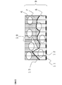
- Adjacent in a layered state is a state in which both continuous resin regions exist adjacent to each other as shown in FIG. 2 as an example, and is confirmed by observing a cross section obtained by cutting perpendicular to the prepreg plane direction. be able to.
- the presence of the reinforcing fibers of [A] contained in both resin regions across the boundary surface between the resin region containing the component [B] and the resin region containing the component [C] makes the component [C].
- the strength of the resin region containing is improved, and the bonding strength is improved.
- the component [A] existing on the boundary surface chemically or / or physically binds to the component [B] and the component [C] to form a resin region including the component [B] and the component [ Adhesion with the resin region containing C] is improved.
- the number of the component [A] existing on the boundary surface may be one or more, and the upper limit is not particularly limited, but is 200 in the observation range described later.
- the interface between the resin region containing the component [B] and the resin region containing the component [C] is included in both resin regions in the plan view of the prepreg, that is, from a viewpoint perpendicular to the prepreg plane direction [ Perpendicular to the prepreg plane containing the fiber of [A] existing across both resin regions from a direction that is 45 degrees different from any fiber direction of A] regardless of whether it is clockwise or counterclockwise. Observed in cross section. By observing the aspect of the resin region at the boundary surface in such a cross section, the adhesion force in the fiber direction and the direction orthogonal to the fiber direction can be evaluated at the same time.
- the roughness average length RSm defined by JIS B0601 (2001) of the cross-sectional curve formed by the boundary surface is 100 ⁇ m or less, not only the chemical and / or physical bonding force but also the physical and chemical binding force .
- the mechanical bonding force of entanglement is also added, and the resin region containing the component [B] and the resin region containing the component [C] are less likely to be separated, which is preferable.
- the lower limit is not particularly limited, but is preferably 15 ⁇ m or more from the viewpoint of avoiding a decrease in mechanical bonding force due to stress concentration.
- the roughness average height Rc of the cross-sectional curve is 3.5 ⁇ m or more, not only the mechanical binding force is expressed by confounding, but also the component [A] existing on the boundary surface is the component [B]. ] And the constituent element [C] chemically or / or physically bonded to improve the adhesion between the resin region containing the constituent element [B] and the resin region containing the constituent element [C], which is preferable.
- a more preferable range of the roughness average height Rc of the cross-sectional curve is 10 ⁇ m or more, in which the component [A] is likely to be included in both resin regions and the adhesion is further improved, and particularly preferably 20 ⁇ m or more.
- the upper limit value is not particularly limited, but is preferably 100 ⁇ m or less from the viewpoint of avoiding a decrease in mechanical bonding force due to stress concentration.
- a known method can be used as a method for measuring the roughness average height Rc and the roughness average length RSm of the cross-sectional curve.
- a method of curing the component [B] and then measuring from a cross-sectional image acquired by using an X-ray CT a method of measuring from an elemental analysis mapping image by an energy dispersive X-ray spectroscope (EDS), or an optical method.
- EDS energy dispersive X-ray spectroscope
- optical method examples thereof include a method of measuring from a cross-sectional observation image by a microscope, a scanning electron microscope (SEM), or a transmission electron microscope (TEM).
- SEM scanning electron microscope
- TEM transmission electron microscope
- component [B] and / or component [C] may be stained to adjust contrast.
- the roughness average height Rc and the roughness average length RSm of the cross-sectional curve are measured in the range of 500 ⁇ m square.
- FIG. 1 An example of a method for measuring the average roughness height Rc and the average roughness RSm of the cross-section curve (measurement method 1 for the cross-section curve element) is shown with reference to FIG.
- the vertical baseline 12 is drawn at intervals of 5 ⁇ m.
- the points where the vertical baseline drawn from the reference line intersects the component [C] for the first time are plotted, and the line connecting the plotted points is defined as the cross-sectional curve 13.
- the obtained cross-section curve 13 is subjected to a filtering process based on JIS B0601 (2001), and the roughness average height Rc and the roughness average length RSm of the cross-section curve 13 are calculated.
- the resin region containing [B] and the resin region containing [C] form a layer and are adjacent to each other to form the boundary surface from the viewpoint of exhibiting excellent mechanical properties.
- the basis weight of the thermoplastic resin of the component [C] is preferably 10 g / m 2 or more.
- a sufficient thickness for exhibiting excellent bonding strength can be obtained, which is preferable.
- the upper limit is not particularly limited, but it is preferably 500 g / m 2 or less because the amount of the thermoplastic resin does not become too large as compared with the reinforcing fiber and a laminated body having excellent specific strength and specific elastic modulus can be obtained.
- the basis weight refers to the mass (g) of the component [C] contained in 1 m 2 of the prepreg.
- the prepreg of the present invention preferably has a reinforcing fiber amount of 30 to 2,000 g / m 2 per unit area.
- the amount of the reinforcing fibers is 30 g / m 2 or more, the number of laminated fibers for obtaining a predetermined thickness at the time of molding the laminate can be reduced, and the work is easy to be simplified.
- the amount of reinforcing fibers is 2,000 g / m 2 or less, the drape property of the prepreg is likely to be improved.
- the reinforcing fiber mass content of the prepreg of the present invention is preferably 30 to 90% by mass, more preferably 35 to 85% by mass, and further preferably 40 to 80% by mass.
- the range may be a combination of any of the above upper limits and any of the lower limits.
- the laminate of the present invention satisfies the following forms.
- a layer containing the components [A], [C] and [D] is included, and [D] has a rubber state elastic modulus of 10 MPa or more at a temperature obtained by adding 50 ° C. to the glass transition temperature, and contains [C].
- the resin region 7 including the component [C] is in close contact with the resin region 8 including the component [D]
- the resin region 7 including the component [C] is in close contact with the resin region 8.
- the surface in which the resin region 8 including the component [D] and the resin region 8 are in close contact with each other is shown as a boundary surface 10.
- a plurality of components [A] 6 are present on the boundary surface 10.
- the component [A] 6 on the boundary surface 10 is in contact with both the resin region 7 including the component [C] and the resin region 8 including the component [D].
- the state in which the component [C] and the component [D] are in contact with each other around the reinforcing fiber can be said to be a state in which the reinforcing fiber is "included in both resin regions across the boundary surface".
- the laminate of the present invention when viewed in a plan view, it is perpendicular to the plane direction of the laminate regardless of whether it is clockwise or counterclockwise with respect to the fiber direction of any [A] contained in both resin regions. Observation obtained by cutting at a 45-degree angle from a different viewpoint, perpendicular to the plane of the laminate containing [A] existing across both resin regions, that is, perpendicular to the plane direction of the laminate.
- the roughness average length RSm defined by JIS B0601 (2001) of the cross-sectional curve formed by the interface between the two resin regions in close contact is 100 ⁇ m or less, and the roughness average height Rc is 3.5 ⁇ m or more. Is preferable.
- the roughness average height Rc is more preferably 10 ⁇ m or more.
- the lower limit of RSm and the upper limit of Rc are not particularly limited, but RSm is preferably 15 ⁇ m or more, and Rc is preferably 100 ⁇ m or less from the viewpoint of concern about a decrease in mechanical bonding force due to stress concentration.
- the average roughness height Rc and the average roughness RSm of the cross-sectional curve can be obtained by the above method in the same manner as the prepreg measurement method of the present invention.
- the resin region containing [C] and the resin region containing [D] form a layer and are adjacent to each other to form the boundary surface from the viewpoint of exhibiting excellent mechanical properties.
- Adjacent in a layered state is a state in which both continuous resin regions exist adjacent to each other as shown in FIG. 2 as an example, and is confirmed by observing a cross section obtained by cutting perpendicular to the plane direction of the laminate. can do.
- a method for molding the laminate of the present invention for example, a press molding method, an autoclave molding method, a bagging molding method, a wrapping tape method, an internal pressure molding method, a hand lay-up method, a filament winding method, a pull-fusion method, a resin -It can be manufactured by a molding method such as an injection molding method or a resin transfer molding method.
- the laminate of the present invention can be produced by laminating the above-mentioned prepreg of the present invention alone or together with other prepregs to form at least a part of the prepreg, and pressing and heating to cure the prepreg. ..
- a method of applying heat and pressure for example, a press molding method, an autoclave molding method, a bagging molding method, a wrapping tape method, an internal pressure molding method and the like are adopted.
- the thermoplastic resin of the component [C] is present on the surface or between the layers. It is preferred that the component [C] is present both on the surface and between the layers. Due to the presence of the thermoplastic resin of the component [C] on the surface of the laminate, the laminate of the present invention can be bonded to the same or different members through the component [C] by welding. When the thermoplastic resin component [C] between the layers of the laminate are present, excellent interlaminar fracture toughness (G IC and G IIC) is obtained.
- a member that is, a member (adhesion material) of the same type and / or a different type as the member constituting the laminate is present on the surface of the laminate by some heating means [C].
- members include members made of thermoplastic resin and members made of metal material.
- the member made of a thermoplastic resin may contain reinforcing fibers, fillers, and the like.
- the integration method is not particularly limited, and examples thereof include heat welding, vibration welding, ultrasonic welding, laser welding, resistance welding, induction welding, insert injection molding, and outsert injection molding.
- the strength of the joint of the integrated members can be evaluated based on ISO4587: 1995 (JIS K6850 (1994)).
- the tensile shear joint strength measured based on ISO4587: 1995 is preferably 25 MPa or more, more preferably 28 MPa or more when the test environment temperature is 23 ° C.
- the laminate can be used for bonding for structural materials, and compared with the tensile shear bonding strength (about 10 MPa) when the test environment temperature of a general adhesive is 23 ° C. Even high strength.
- the test environment temperature when the test environment temperature is 80 ° C., it is preferable to show a bonding strength of 13 MPa or more, more preferably 16 MPa or more in the evaluation based on ISO4587: 1995.
- the upper limit of the tensile shear joint strength at a test environment temperature of 23 ° C. or 80 ° C. is 200 MPa. ..
- the laminate of the present invention is preferably used for computer applications such as aircraft structural members, wind turbine blades, automobile outer panels, IC trays and laptop housings, and for sports applications such as golf shafts and tennis rackets.
- the unit "parts" of the composition ratio means parts by mass unless otherwise specified. Unless otherwise specified, various characteristics were measured in an environment with a temperature of 23 ° C. and a relative humidity of 50%.
- PA6 Polyetherketone 6 (“Amylan” (registered trademark) CM1007 (manufactured by Toray Co., Ltd., melting point 225 ° C., glass transition temperature 48 ° C.)) with a grain of 120 g / m 2 -PPS: Polyphenylene sulfide ("Trelina” (registered trademark) A670T05 (manufactured by Toray Co., Ltd., melting point 278 ° C, glass transition temperature 90 ° C)) with a grain of 120 g / m 2
- PEKK1 Polyetherketoneketone ( A film with a grain size of 120 g / m 2 consisting of "KEPSTAN” (registered trademark) 6002 (manufactured by Alchema, melting point 300 ° C., glass transition temperature 160 ° C.)
- PEKK2 polyetherketoneketone (“KEPSTAN” (registered trademark) 7002 (
- thermoplastic resin (1) Method for Measuring Melting Point and Glass Transition Temperature of Thermoplastic Resin The melting point and glass transition temperature of the thermoplastic resin were measured using a differential scanning calorimeter (DSC) based on JIS K7121 (2012). When multiple melting points or glass transition temperatures were observed in a mixture or the like, the highest melting point was adopted as the melting point of the thermoplastic resin.
- DSC differential scanning calorimeter
- thermosetting resin compositions of each specific example shown in Table 1 were prepared using the following compounds.
- Aldite (registered trademark) MY721, manufactured by Huntsman Advanced Materials Co., Ltd.
- Viscosity adjuster-polyether sulfone (Sumika Excel” (registered trademark) PES5003P, manufactured by Sumitomo Chemical Co., Ltd.).
- Phosphorus compound / red phosphorus flame retardant (“Novaled” (registered trademark) 120, manufactured by Phosphorus Chemical Industry Co., Ltd., phosphorus atom content 85% by mass).
- thermosetting resin composition The epoxy resin and viscosity modifier shown in Table 1 were put into a kneading device and kneaded by heating to dissolve the viscosity modifier (however, the viscosity modifier). May not be added). Then, the temperature is lowered to 100 ° C. or lower while continuing kneading, and an appropriately selected amine compound, curing catalyst and phosphorus compound shown in Table 1 (curing catalyst and phosphorus compound may not be added) are added. Stirred to obtain thermosetting resin compositions B-1 to B-10.
- thermosetting resin composition prepared by the above method is injected into a mold, and the temperature is raised from 30 ° C. to the curing temperature shown in Table 1 at a rate of 1.5 ° C./min in a hot air dryer, and the results are shown in Table 1.
- Curing time After heat curing the temperature was lowered to 30 ° C. at a rate of 2.5 ° C./min to prepare a plate-shaped thermosetting resin cured product having a thickness of 2 mm.
- the component [B] is a cured product of a curable resin
- the component [D] is a cured product of a thermosetting resin. From the obtained cured thermosetting resin, each specific example shown in Table 1 was evaluated by the following method.
- a test piece having a width of 12.7 mm and a length of 45 mm was cut out from the cured resin plate prepared by the above method, and the test piece was dried in a vacuum oven at 60 ° C. for 24 hours, and according to JIS K 7244-7 (2007).
- a storage elastic modulus curve was obtained by a dynamic viscoelasticity test, and in such a storage elastic modulus curve, the value of the temperature at the intersection of the tangent line in the glass state and the tangent line in the transition state was defined as the glass transition temperature.
- the measurement was performed at a heating rate of 5 ° C./min and a frequency of 1 Hz.
- the storage elastic modulus at a temperature higher than the obtained glass transition temperature by 50 ° C. was defined as the rubber state elastic modulus.
- thermosetting resin cured product A test piece having a length of 60 mm and a width of 10 mm is cut out from the resin cured product plate produced by the above method, and the test piece is dried in a vacuum oven at 60 ° C. for 24 hours, and the material universal testing machine (Instron Japan Co., Ltd.) A three-point bending test was performed at a test speed of 2.5 mm / min and a distance between fulcrums of 32 mm using "Instron” (registered trademark) 5565 type P8564) manufactured by JIS K7171 (1994) to determine the bending strength.
- Instron registered trademark
- the prepreg was prepared by the following two methods.
- the components used in each example are as shown in Tables 2 and 3.
- Prepreg [I] A continuous reinforcing fiber sheet in which the reinforcing fibers (grain 193 g / m 2 ) of the component [A] are aligned in one direction is pulled out, and while running in one direction, the grain 120 g / consisting of the component [C] the resin sheet m 2 arranged in the continuous reinforcing fiber sheet, to melt the components by heating with an IR heater [C], is adhered to the continuous reinforcing fiber sheet entire one surface, the surface temperature of a component of [C]
- the fiber-reinforced resin intermediate was obtained by pressurizing with a nip roll kept below the melting point and cooling the impregnated fiber sheet.
- thermosetting resin composition according to the component [B] selected as shown in Tables 2 and 3 is coated on a release paper with a resin grain of 100 g / m 2 using a knife coater to prepare a thermosetting resin film. After that, the thermosetting resin film is superposed on the opposite surface impregnated with the component [C] in the intermediate, and the intermediate is impregnated with the thermosetting resin composition while being heated and pressed by a heat roll to impregnate the intermediate. [I] was obtained.
- thermosetting resin composition according to the component [B] selected as shown in Tables 2 and 3 was coated on a release paper with a resin basis weight of 50 g / m 2 using a knife coater to prepare a resin film.
- This resin film is laminated on both sides of the reinforcing fibers (grain 193 g / m 2 ) of the component [A] aligned in one direction, and the thermosetting resin composition is made into carbon fibers while heating and pressurizing using a heat roll. Was impregnated to obtain prepreg [II].
- Two pieces of the obtained laminate were cut into a shape having a width of 250 mm and a length of 92.5 mm with the 0 ° direction as the length direction of the test piece, and dried in a vacuum oven for 24 hours. After that, the two panels cut into a shape having a width of 250 mm and a length of 92.5 mm were superposed with the 0 ° direction as the length direction and the width as 25 mm ⁇ the length as 12.5 mm, and the component [C] used.
- a pressure of 3 MPa was applied at a temperature 20 ° C. higher than the melting point of the thermoplastic resin and the mixture was held for 1 minute to weld the overlapped surfaces to obtain an integrally molded product.
- a tab was adhered to the obtained integrally molded product in accordance with ISO4587: 1995 (JIS K6850 (1994)), and the tab was cut to a width of 25 mm to obtain a desired test piece.
- a rectangular test piece having a length of 80 mm and a width of 15 mm was cut out with the reinforcing fiber axial direction as the length direction of the test piece.
- the obtained test piece is dried in a vacuum oven at 60 ° C. for 24 hours, and conforms to SACMA-SRM 1R-94, and is a universal material testing machine (manufactured by Instron Japan Co., Ltd., "Instron” (registered trademark). ) 5565 type P8564) was used to measure the compressive strength in an environment of 23 ° C., and the evaluation was made as follows based on the measurement results. The results are shown in the table.
- a rectangular test piece having a length of 150 mm and a width of 20 mm was cut out with the reinforcing fiber shaft as the length direction of the test piece, and dried in a vacuum oven at 60 ° C. for 24 hours.
- Example 1 to 16 laminates were prepared by the methods described in (1) the method for measuring tensile shear joint strength and (2) the method for measuring compressive strength.
- Examples 1 to 3 As shown in Table 1, in Examples 1 to 3, the elastic modulus in the rubber state of the thermosetting resin cured product improves as the blending amount of the trifunctional or higher functional glycidylamine type epoxy resin (tetraglycidyldiaminodiphenylmethane) increases. It showed a tendency. As shown in Table 2, as the blending amount of tetraglycidyldiaminodiphenylmethane increased, the tensile shear joint strength and the compressive strength improved, showing a preferable tendency.
- Example 1 and Comparative Examples 1 and 2 In Example 1, as shown in Table 2, by using a thermosetting resin having a high elastic modulus in a rubber state as the component [B], Comparative Examples 1 and 2 (thermosetting resin rubber) shown in Table 3 are used. It was shown that the tensile shear joint strength and the compressive strength of the laminated body are superior to those of the state elastic modulus (less than 10 MPa).
- Example 1 and Examples 4 and 5 As shown in Table 1, in Examples 4 and 5, different thermosetting resin compositions from Example 1 were used, and as shown in Table 2, compared with Example 1, at 80 ° C. The tensile-shear joint strength and the compressive strength tended to decrease slightly, but both showed excellent characteristics.
- Example 1 and Examples 6 and 7 As shown in Table 1, in Examples 6 and 7, as compared with Example 1, the bending strength of the thermosetting resin cured product tends to decrease as the phosphorus compound compounding amount increases. As described in No. 2, the tensile shear joint strength at 23 ° C. and the tensile shear joint strength at 80 ° C. tended to decrease slightly, but both showed excellent characteristics.
- Example 8 was prepared in the same manner as in Example 1 except that no viscosity modifier was used. As shown in Table 2, Example 8 exhibited excellent characteristics as in Example 1.
- Example 1 and Examples 9 and 10 As shown in Table 2, when reinforcing fibers having different strand tensile strengths were used in Examples 9 and 10, the higher the strand tensile strength, the higher the tensile shear joint strength at 23 ° C. and 80 as compared with Example 1. The tensile-shear joint strength at ° C was improved, showing favorable characteristics.
- Example 1 and Comparative Example 3 A film of polyamide 6 (“Amiran” (registered trademark) CM1007 (manufactured by Toray Industries, Inc.)) with a film grain of 50 g / m 2 was attached to both sides of the reinforcing fiber sheets arranged in a unidirectional plane, and at 250 ° C. By heating and pressurizing, a prepreg having a reinforced carbon fiber grain of 193 g / m 2 was obtained. The obtained prepreg is cut to a predetermined size, and after laminating 6 sheets in the same direction for [0 ° / 90 °] 2s or in the same direction for joint strength evaluation and compression strength evaluation, respectively, the pressure is 3 MPa with a press machine.
- a film of polyamide 6 (“Amiran” (registered trademark) CM1007 (manufactured by Toray Industries, Inc.)
- CM1007 manufactured by Toray Industries, Inc.
- Example 17 it was prepared a laminate by the method described in the measurement method (3) an interlayer fracture toughness (G IC and G IIC).
- the above prepreg [I] is cut to a predetermined size, and a total of 20 prepregs are laminated with the side where the component [C] is present facing upward so that the same reinforcing fiber direction is obtained, and the central 10 sheets are laminated.
- a release film for introducing a preliminary crack was sandwiched between the eyes and the eleventh sheet to prepare a preform.
- Comparative Example 4 the prepreg [II] (without the component [C]) was cut to a predetermined size, laminated in the same manner as in Example 17, and the release film was sandwiched to obtain a preform.
- Comparative Example 5 polyamide particles (SP-500, manufactured by Toray Industries, Inc.) were placed on one side surface of the prepreg [II] (not containing the component [C]) cut to a predetermined size per prepreg unit area. After uniformly spraying so that the particle amount was 7 g / m 2 , the particles were laminated in the same manner as in Example 17, and the release film was sandwiched to obtain a preform.
- SP-500 manufactured by Toray Industries, Inc.
- Example 17 and Comparative Examples 4 and 5 the obtained preforms were subjected to a pressure of 0.6 MPa with a press and heated at 180 ° C. for 120 minutes to obtain a laminate, and then the above-mentioned Examples. It was evaluated by the method described, interlaminar fracture toughness value (G IC and G IIC) to. As shown in Tables 2 and 3, Example 17 containing the component [C] between the layers of the laminate includes Comparative Example 4 containing no component [C] and Comparative Example 5 containing the thermoplastic resin as different forms. It showed an excellent interlayer fracture toughness value.
Landscapes
- Chemical & Material Sciences (AREA)
- Engineering & Computer Science (AREA)
- Composite Materials (AREA)
- Mechanical Engineering (AREA)
- Physics & Mathematics (AREA)
- Mathematical Physics (AREA)
- Materials Engineering (AREA)
- Inorganic Chemistry (AREA)
- Manufacturing & Machinery (AREA)
- Health & Medical Sciences (AREA)
- Chemical Kinetics & Catalysis (AREA)
- Medicinal Chemistry (AREA)
- Polymers & Plastics (AREA)
- Organic Chemistry (AREA)
- Textile Engineering (AREA)
- Reinforced Plastic Materials (AREA)
- Laminated Bodies (AREA)
Abstract
Description
特許文献4には、強化繊維と熱硬化性樹脂からなるプリプレグの表層に、熱可塑性樹脂からなる粒子、または繊維、またはフィルムが配置されてなるプリプレグおよびその繊維強化複合材料が示されている。
[A]強化繊維
[B]熱硬化性樹脂
[C]熱可塑性樹脂。
[A]強化繊維
[C]熱可塑性樹脂
[D]熱硬化性樹脂硬化物。
硬化度(%)=((熱硬化性樹脂を含む組成物の硬化前の発熱量)-(熱硬化性樹脂の硬化物の発熱量))/(熱硬化性樹脂を含む組成物の硬化前の発熱量)×100。
以下に示す構成要素[A]、[B]、[C]及び[D]を用いた。それぞれの実施例および比較例で用いた構成要素は、表1から3に示すとおりである。
・T800:炭素繊維(“トレカ(登録商標)”T800S-24K、東レ(株)製、ストランド引張強度:5.9GPa)
・T1100:炭素繊維(“トレカ(登録商標)”T1100G-24K、東レ(株)製、ストランド引張強度:7.0GPa)
・T700:炭素繊維(“トレカ(登録商標)”T700S-24K、東レ(株)製、ストランド引張強度:4.9GPa)。
・PA6:ポリアミド6(“アミラン”(登録商標)CM1007(東レ(株)製、融点225℃、ガラス転移温度48℃))からなる目付120g/m2のフィルム
・PPS:ポリフェニレンスルフィド(“トレリナ”(登録商標)A670T05(東レ(株)社製、融点278℃、ガラス転移温度90℃))からなる目付120g/m2のフィルム
・PEKK1:ポリエーテルケトンケトン(“KEPSTAN”(登録商標)6002(アルケマ社製、融点300℃、ガラス転移温度160℃))からなる目付120g/m2のフィルム
・PEKK2:ポリエーテルケトンケトン(“KEPSTAN”(登録商標)7002(アルケマ社製、融点331℃、ガラス転移温度162℃))からなる目付120g/m2のフィルム
・PEEK:ポリエーテルエーテルケトン(PEEK 450G(Victrex社製、融点343℃、ガラス転移温度143℃))からなる目付120g/m2のフィルム
・PEI:ポリエーテルイミド(“ULTEM”(登録商標)1010 SABIC社製、ガラス転移温度217℃)からなる目付120g/m2のフィルム
・半芳香族PA:ポリアミド6T(融点320℃、ガラス転移温度125℃))からなる目付120g/m2のフィルム。
(1)熱可塑性樹脂の融点およびガラス転移温度の測定方法
熱可塑性樹脂の融点およびガラス転移温度は、JIS K7121(2012)に基づいて、示差走査熱量計(DSC)を用いて測定した。混合物などで融点またはガラス転移温度が複数観測される場合は、最も高い融点をその熱可塑性樹脂の融点として採用した。
表1に記載の各具体例の熱硬化性樹脂組成物を、以下の化合物を用いて作製した。
・テトラグリシジルジアミノジフェニルメタン(“アラルダイト”(登録商標)MY721、ハンツマン・アドバンスト・マテリアルズ社製)エポキシ当量:113(g/eq.)、4官能のグリシジルアミン型エポキシ樹脂)
・ビスフェノールA型エポキシ樹脂(“jER”(登録商標)825、三菱ケミカル(株)製)エポキシ当量:175(g/eq.))
・フェノールノボラック型エポキシ樹脂(“jER”(登録商標)154、三菱ケミカル(株)製)エポキシ当量:178(g/eq.))
・ビスフェノールA型エポキシ樹脂(“jER”(登録商標)1001、三菱ケミカル(株)製)エポキシ当量:475(g/eq.))。
・4,4’-ジアミノジフェニルスルホン(セイカキュアS、和歌山精化工業(株)製)
・ジシアンジアミド(DICY7、三菱ケミカル(株)製)。
3-(3,4-ジクロロフェニル)1,1-ジメチルウレア(DCMU99、保土ヶ谷化学工業(株)製)。
・ポリエーテルスルホン(“スミカエクセル”(登録商標)PES5003P 住友化学(株)製)。
・赤リン系難燃剤(“ノーバレッド”(登録商標)120、燐化学工業(株)製、リン原子含有量85質量%)。
混練装置中に、表1に記載のエポキシ樹脂および粘度調整剤を投入し、加熱混練を行い、粘度調整剤を溶解させた(ただし、粘度調整剤を加えない場合もある)。次いで、混練を続けたまま100℃以下の温度まで降温させ、表1に記載のアミン化合物、硬化触媒およびリン化合物から適宜選択されたもの(硬化触媒およびリン化合物は加えない場合もある)を加えて撹拌し、B-1~B-10までの熱硬化性樹脂組成物を得た。
上記の方法で調製した熱硬化性樹脂組成物をモールドに注入し、熱風乾燥機中で30℃から速度1.5℃/分で表1に記載の硬化温度まで昇温し、表1に記載の硬化時間加熱硬化した後、30℃まで速度2.5℃/分で降温して、厚さ2mmの板状の熱硬化性樹脂硬化物を作製した。構成要素[B]硬化性樹脂の硬化物であり、構成要素[D]熱硬化性樹脂硬化物である。得られた熱硬化性樹脂硬化物より、以下の方法にて、表1に記載の各具体例の評価を実施した。
上記の方法で作製した樹脂硬化物板から、幅12.7mm、長さ45mmの試験片を切り出し、試験片を60℃真空オーブン中で24時間乾燥させ、JIS K 7244-7(2007)に従い、動的粘弾性試験により貯蔵弾性率曲線を得て、かかる貯蔵弾性率曲線において、ガラス状態での接線と転移状態での接線との交点における温度の値をガラス転移温度とした。ここでは、昇温速度5℃/分、周波数1Hzで測定した。得られたガラス転移温度を50℃上回る温度での貯蔵弾性率を、ゴム状態弾性率とした。
上記の方法で作製した樹脂硬化物板から、長さ60mm、幅10mmの試験片を切り出し、試験片を60℃真空オーブン中で24時間乾燥させ、材料万能試験機(インストロン・ジャパン(株)製、“インストロン”(登録商標)5565型P8564)を用い、試験速度2.5mm/分、支点間距離32mmで3点曲げ試験を行い、JIS K7171(1994)に従い曲げ強度を求めた。
プリプレグは、以下の2種の方法により作製した。各例で使用した構成要素は表2,3記載のそれぞれのとおりである。
構成要素[A]の強化繊維(目付193g/m2)を、一方向に整列させた連続した状態の強化繊維シートを引き出し、一方向に走行させつつ、構成要素[C]からなる目付120g/m2の樹脂シートを連続強化繊維シート上に配置して、IRヒータで加熱して構成要素[C]を溶融し、連続強化繊維シート片面全面に付着させ、表面温度が構成要素[C]の融点以下に保たれたニップロールで加圧して、強化繊維シートに含浸したものを冷却させて繊維強化樹脂中間体を得た。表2,3記載のとおり選定した構成要素[B]に係る熱硬化性樹脂組成物を、ナイフコーターを用いて樹脂目付100g/m2で離型紙上にコーティングし、熱硬化性樹脂フィルムを作製した後、上記中間体における構成要素[C]を含浸させた反対の表面に上記熱硬化性樹脂フィルムを重ね、ヒートロールにより加熱加圧しながら熱硬化性樹脂組成物を中間体に含浸させ、プリプレグ[I]を得た。
表2,3記載のとおり選定した構成要素[B]に係る熱硬化性樹脂組成物を、ナイフコーターを用いて樹脂目付50g/m2で離型紙上にコーティングし、樹脂フィルムを作製した。この樹脂フィルムを、一方向に引き揃えた構成要素[A]の強化繊維(目付193g/m2)の両側に重ね合せてヒートロールを用い、加熱加圧しながら熱硬化性樹脂組成物を炭素繊維に含浸させ、プリプレグ[II]を得た。
(1)引張せん断接合強度の測定方法
上記で作製したプリプレグ[I]および[II]を所定の大きさにカットし、プリプレグ[I]を2枚とプリプレグ[II]を6枚得た。強化繊維の軸方向を0°とし、軸直交方向を90°と定義して、[0°/90°]2s(記号sは、鏡面対称を示す)で積層し、プリフォームを作製した。このときプリフォームの両面それぞれの最外層の2枚はプリプレグ[I]となるように積層した。すなわち、プリプレグ[I]2枚がプリプレグ[II]6枚を挟み込むように積層した。プリフォームの両の表層が、構成要素[C]を含む熱可塑性樹脂層となるように配置した。すなわち、プリプレグ[I]の構成要素[C]を含浸させた面が外側になるように配置した。このプリフォームをプレス成形金型にセットし、必要に応じ、治具やスペーサーを使用して、この形状を維持させたまま、プレス機で0.6MPaの圧力をかけ、表2,3に記載の条件で加温することで、積層体を得た。構成要素[C]の存在位置は積層体の表面である。
(a)23℃での引張せん断接合強度
28MPa以上:A
25MPa以上28MPa未満:B
20MPa以上25MPa未満:C
20MPa未満:D(不合格)
(b)80℃での引張せん断接合強度
16MPa以上:A
13MPa以上16MPa未満:B
10MPa以上13MPa未満:C
10MPa未満:D(不合格)。
上記で作製したプリプレグ[I]および[II]を所定の大きさにカットし、プリプレグ[I]を2枚とプリプレグ[II]を4枚得た。両面それぞれの最外層の2枚はプリプレグ[I]として、間に4枚のプリプレグ[II]を挟んで、全て同一の強化繊維方向となるよう、計6枚積層し、プリフォームを作製した。このとき、プリフォームの両の表層が構成要素[C]を含む熱可塑性樹脂層となるように配置した。このプリフォームをプレス成形金型にセットし、必要に応じ、治具やスペーサーを使用して、この形状を維持させたまま、プレス機で0.6MPaの圧力をかけ、表2,3に記載の条件で加温することで、積層体を得た。構成要素[C]の存在位置は積層体の表面である。
1.6GPa以上:A
1.4GPa以上1.6GPa未満:B
1.2GPa以上1.4GPa未満:C
1.2GPa未満:D(不合格)。
上記で作製したプリプレグ[I]を所定の大きさにカットし、同一の強化繊維方向となるよう、全てのプリプレグを構成要素[C]が存在する面を上向きにして、計20枚積層した。このとき、中央の10枚目と11枚目の間の位置に予備亀裂導入のための離型フィルムを挟み込み、プリフォームを作製した。このプリフォームをプレス成形金型にセットし、必要に応じ、治具やスペーサーを使用して、この形状を維持させたまま、プレス機で0.6MPaの圧力をかけ、180℃で120分間加温することで、積層体を得た。構成要素[C]の存在位置は積層体の層間および片側の表面である。
上記で作製したプリプレグ[I]または積層体を用いる。図1で示す通り、プリプレグの場合においては、前記両樹脂領域に含まれる任意の[A]の繊維方向4に対し、プリプレグの平面視、すなわちプリプレグ平面方向に対し垂直な視点における45度の角度にて、プリプレグ平面方向に対し垂直にカットした観察断面5において、光学顕微鏡を用いて、1000倍の画像を撮影した。得られた画像中の任意の500μm四方の観察範囲において、前記断面曲線要素の測定方法1により得られる断面曲線要素のJIS B0601(2001)で定義される、粗さ平均長さRSmおよび粗さ平均高さRcを測定した。積層体の場合も同様である。
実施例1~16では、(1)引張せん断接合強度の測定方法に記載の方法、および(2)圧縮強度の測定方法に記載の方法で積層体を作成した。
表1に記載の通り、実施例1~3では、3官能以上のグリシジルアミン型エポキシ樹脂(テトラグリシジルジアミノジフェニルメタン)の配合量が増えるに従い、熱硬化性樹脂硬化物のゴム状態弾性率が向上する傾向を示した。表2に記載の通り、テトラグリシジルジアミノジフェニルメタンの配合量が増加するに従い、引張せん断接合強度および圧縮強度が向上し、好ましい傾向を示した。
実施例1では、表2に記載の通り、構成要素[B]としてゴム状態弾性率の高い熱硬化性樹脂を用いることで、表3に記載の比較例1および2(熱硬化性樹脂のゴム状態弾性率が10MPa未満)と比べ、積層体として、引張せん断接合強度および圧縮強度が優れていることを示した。
表1に記載の通り、実施例4および実施例5では、実施例1と異なる熱硬化性樹脂組成物を使用したところ、表2に記載の通り、実施例1と比較すると、80℃での引張せん断接合強度および圧縮強度が若干低下する傾向を示したが、いずれも優れた特性を示した。
表1に記載の通り、実施例6および実施例7では、実施例1と比較すると、リン化合物配合量の増加に伴い、熱硬化性樹脂硬化物の曲げ強度が低下する傾向が見られ、表2に記載の通り、23℃での引張せん断接合強度および80℃での引張せん断接合強度が若干低下する傾向が見られたが、いずれも優れた特性を示した。
表2に記載の通り、実施例8は粘度調整剤を用いないこと以外は、実施例1と同様に作製した。表2に記載の通り、実施例8は実施例1と同様に優れた特性を示した。
表2に記載の通り、実施例9および10では、ストランド引張強度の異なる強化繊維を用いたところ、実施例1と比較すると、ストランド引張強度が高いほど、23℃での引張せん断接合強度および80℃での引張せん断接合強度が向上し、好ましい特性を示した。
表2に記載の通り、実施例11~16では、実施例1に比べガラス転移温度の高い構成要素[C]を用いたところ、実施例1に比べ、80℃での引張せん断接合強度が向上し、好ましい特性を示した。
一方向平面状に配列させた強化繊維シートの両面に、フィルム目付50g/m2のポリアミド6(“アミラン”(登録商標)CM1007(東レ(株)製))のフィルムを貼り付け、250℃で加熱加圧して、強化炭素繊維目付193g/m2のプリプレグを得た。得られたプリプレグを、所定のサイズにカットし、それぞれ、接合強度評価用および圧縮強度評価用に、[0°/90°]2sまたは同一方向に6枚積層した後、プレス機で3MPaの圧力をかけ、250℃で10分間加温することで、それぞれ積層体を得た。得られた積層体より、実施例に記載の方法で接合強度と圧縮強度を測定した。表3に示す通り、熱硬化性樹脂非含有であるため、実施例1に比べて80℃での引張せん断接合強度および圧縮強度が低く、構造材料として十分な特性を示さなかった。
実施例17では、(3)層間破壊靱性値(GICおよびGIIC)の測定方法に記載の方法で積層体を作成した。上記プリプレグ[I]を所定の大きさにカットし、同一の強化繊維方向となるよう、全てのプリプレグを構成要素[C]が存在する面を上向きにして計20枚積層し、中央の10枚目と11枚目の間の位置に予備亀裂導入のための離型フィルムを挟み込み、プリフォームを作製した。比較例4では、プリプレグ[II](構成要素[C]非含有)を所定の大きさにカットし、実施例17と同じ方法で積層し、離型フィルムを挟み込み、プリフォームを得た。比較例5では、所定の大きさにカットしたプリプレグ[II](構成要素[C]非含有)の片側表面に、ポリアミド粒子(SP-500、東レ(株)製)を、プリプレグ単位面積あたりの粒子量が7g/m2となるよう均一に散布したのち、実施例17と同じ方法で積層し、離型フィルムを挟み込み、プリフォームを得た。実施例17、比較例4,5とも、得られたプリフォームを、プレス機で0.6MPaの圧力をかけ、180℃で120分間加温することで、積層体を得た後、上記実施例に記載の方法で、層間破壊靱性値(GICおよびGIIC)を評価した。表2および3に記載の通り、構成要素[C]を積層体の層間に含む実施例17は、構成要素[C]非含有の比較例4、および熱可塑性樹脂を異なる形態として含む比較例5に比べ、優れた層間破壊靱性値を示した。


2:構成要素[A]
3:構成要素[C]および構成要素[B]または構成要素[C]および構成要素[D]
4:繊維方向
5:観察断面
6:構成要素[A]
7:構成要素[C]を含む樹脂領域
8:構成要素[B]を含む樹脂領域または構成要素[D]を含む樹脂領域
9:観察画像
10:境界面
11:基準線
12:垂基線
13:断面曲線
Claims (26)
- 次の構成要素[A]、[B]及び[C]を含むプリプレグであって、
[B]は、硬化度が90%以上の状態でのガラス転移温度に50℃を加えた温度におけるゴム状態弾性率が10MPa以上であり、
プリプレグの表面に[C]が存在しており、
[B]を含む樹脂領域と[C]を含む樹脂領域との境界面をまたいで両樹脂領域に含まれる[A]の強化繊維が存在するプリプレグ。
[A]強化繊維
[B]熱硬化性樹脂
[C]熱可塑性樹脂 - 前記プリプレグの平面視において、前記両樹脂領域に含まれる任意の[A]の繊維方向に対し45度異なる角度の方向から、前記[A]を含むプリプレグ平面に垂直な断面を得た場合に、前記断面において、両樹脂領域の密着する境界面が形成する断面曲線の、JIS B0601(2001)で定義される粗さ平均長さRSmが100μm以下であり、粗さ平均高さRcが3.5μm以上である、請求項1に記載のプリプレグ。
- 前記[B]を含む樹脂領域と[C]を含む樹脂領域がそれぞれ層状をなして隣接することにより前記境界面を形成している、請求項1または2に記載のプリプレグ。
- 構成要素[B]は、硬化度が90%以上の状態でのガラス転移温度に50℃を加えた温度におけるゴム状態弾性率が12MPa以上である、請求項1から3のいずれかに記載のプリプレグ。
- 構成要素[B]は、硬化度が90%以上の状態でのガラス転移温度に50℃を加えた温度におけるゴム状態弾性率が15MPa以上である、請求項1から3のいずれかに記載のプリプレグ。
- 構成要素[B]は、エポキシ樹脂を含み、
構成要素[B]に含まれる全エポキシ樹脂100質量部に対して3官能以上のグリシジルアミン型エポキシが40~100質量部含まれる、請求項1から5のいずれかに記載のプリプレグ。 - 構成要素[B]を含む組成物は、芳香族アミンを含む、請求項1から6のいずれかに記載のプリプレグ。
- 構成要素[B]を含む組成物は、リンを1.0質量%以下の原子濃度で含む、請求項1から7のいずれかに記載のプリプレグ。
- 構成要素[B]は、硬化度が90%以上の状態での曲げ強度が150MPa以上である、請求項1から8のいずれかに記載のプリプレグ。
- 前記粗さ平均高さRcが10μm以上である、請求項1から9のいずれかに記載のプリプレグ。
- 構成要素[C]は、ガラス転移温度が80℃以上の結晶性の熱可塑性樹脂またはガラス転移温度が160℃以上の非晶性の熱可塑性樹脂から選ばれる1種または2種以上である、請求項1から10のいずれかに記載のプリプレグ。
- 構成要素[C]は、ポリアリーレンエーテルケトン、ポリフェニレンスルフィドまたはポリエーテルイミドから選ばれる1種または2種以上である、請求項1から11のいずれかに記載のプリプレグ。
- 構成要素[A]には、ストランド引張強度が5.5GPa以上の炭素繊維が含まれる、請求項1から12のいずれかに記載のプリプレグ。
- 次の構成要素[A]、[C]及び[D]を含む層が含まれる積層体であって、
[D]はガラス転移温度に50℃を加えた温度におけるゴム状態弾性率が10MPa以上であり、
[C]を含む樹脂領域と[D]を含む樹脂領域との境界面をまたいで両樹脂領域に含まれる[A]の強化繊維が存在する積層体。
[A]強化繊維
[C]熱可塑性樹脂
[D]熱硬化性樹脂硬化物 - 前記積層体の平面視において、前記両樹脂領域に含まれる任意の[A]の繊維方向に対し45度異なる角度の方向から、前記[A]を含む積層体の平面に垂直な断面を得た場合に、前記断面において、両樹脂領域の密着する境界面が形成する断面曲線の、JIS B0601(2001)で定義される粗さ平均長さRSmが100μm以下であり、粗さ平均高さRcが3.5μm以上である、請求項14に記載の積層体。
- 前記[C]を含む樹脂領域と[D]を含む樹脂領域がそれぞれ層状をなして隣接することにより前記境界面を形成している、請求項14または15に記載の積層体。
- 表面に構成要素[C]が存在する、請求項14から16のいずれかに記載の積層体。
- 層間に構成要素[C]が存在する、請求項14から17のいずれかに記載の積層体。
- 構成要素[D]は、ガラス転移温度に50℃を加えた温度におけるゴム状態弾性率が12MPa以上である、請求項14から18のいずれかに記載の積層体。
- 構成要素[D]は、曲げ強度が150MPa以上である、請求項14から19のいずれかに記載の積層体。
- 前記粗さ平均高さRcが10μm以上である、請求項14から20のいずれかに記載の積層体。
- 構成要素[C]は、ガラス転移温度が80℃以上の結晶性の熱可塑性樹脂またはガラス転移温度が160℃以上の非晶性の熱可塑性樹脂から選ばれる1種または2種以上である、請求項14から21のいずれかに記載の積層体。
- 構成要素[C]は、ポリアリーレンエーテルケトン、ポリフェニレンスルフィドまたはポリエーテルイミドから選ばれる1種または2種以上である、請求項14から22のいずれかに記載の積層体。
- 構成要素[A]には、ストランド引張強度が5.5GPa以上の炭素繊維が含まれる、請求項14から23のいずれかに記載の積層体。
- 請求項1から13のいずれかに記載のプリプレグの硬化物が少なくとも一部の層を構成する積層体である、請求項17または18に記載の積層体。
- 別の部材が、構成要素[C]の面に接合することにより、請求項17から25のいずれかに記載の積層体と一体化されてなる、成形品。
Priority Applications (5)
| Application Number | Priority Date | Filing Date | Title |
|---|---|---|---|
| CN202080036510.8A CN113840866B (zh) | 2019-05-23 | 2020-05-15 | 预浸料坯、层叠体及成型品 |
| CN202411848887.XA CN119684743A (zh) | 2019-05-23 | 2020-05-15 | 预浸料坯、层叠体及成型品 |
| US17/607,981 US11840612B2 (en) | 2019-05-23 | 2020-05-15 | Prepreg, laminate, and molding |
| JP2020542929A JP7647099B2 (ja) | 2019-05-23 | 2020-05-15 | プリプレグ |
| EP20810225.1A EP3974467A4 (en) | 2019-05-23 | 2020-05-15 | PREPREG, LAMINATE AND MOLDING |
Applications Claiming Priority (4)
| Application Number | Priority Date | Filing Date | Title |
|---|---|---|---|
| JP2019-097033 | 2019-05-23 | ||
| JP2019097030 | 2019-05-23 | ||
| JP2019-097030 | 2019-05-23 | ||
| JP2019097033 | 2019-05-23 |
Publications (1)
| Publication Number | Publication Date |
|---|---|
| WO2020235484A1 true WO2020235484A1 (ja) | 2020-11-26 |
Family
ID=73458121
Family Applications (1)
| Application Number | Title | Priority Date | Filing Date |
|---|---|---|---|
| PCT/JP2020/019466 Ceased WO2020235484A1 (ja) | 2019-05-23 | 2020-05-15 | プリプレグ、積層体および成形品 |
Country Status (6)
| Country | Link |
|---|---|
| US (1) | US11840612B2 (ja) |
| EP (1) | EP3974467A4 (ja) |
| JP (1) | JP7647099B2 (ja) |
| CN (2) | CN119684743A (ja) |
| TW (1) | TWI884955B (ja) |
| WO (1) | WO2020235484A1 (ja) |
Cited By (1)
| Publication number | Priority date | Publication date | Assignee | Title |
|---|---|---|---|---|
| WO2022107564A1 (ja) * | 2020-11-18 | 2022-05-27 | 東レ株式会社 | エポキシ樹脂組成物、プリプレグ、繊維強化樹脂成形体および一体化成形品 |
Families Citing this family (5)
| Publication number | Priority date | Publication date | Assignee | Title |
|---|---|---|---|---|
| EP3974140A4 (en) * | 2019-05-23 | 2023-06-14 | Toray Industries, Inc. | PREPREG, LAMINATE AND MOLDING |
| JP7676777B2 (ja) * | 2019-12-11 | 2025-05-15 | 東レ株式会社 | プリプレグ、積層体および一体化成形品 |
| JPWO2021246466A1 (ja) * | 2020-06-03 | 2021-12-09 | ||
| CN116194278B (zh) | 2020-07-27 | 2026-03-24 | 东丽株式会社 | 纤维增强塑料及纤维增强塑料的制造方法 |
| CN116438069A (zh) * | 2020-11-18 | 2023-07-14 | 东丽株式会社 | 纤维增强树脂及一体化成型品 |
Citations (7)
| Publication number | Priority date | Publication date | Assignee | Title |
|---|---|---|---|---|
| JPH08259713A (ja) | 1995-03-22 | 1996-10-08 | Toray Ind Inc | プリプレグおよび繊維強化複合材料 |
| JPH10138354A (ja) | 1996-11-08 | 1998-05-26 | Yamaha Corp | 炭素繊維強化樹脂成形物とその製造方法 |
| JP3906319B2 (ja) | 2002-12-27 | 2007-04-18 | 東レ株式会社 | 積層体、一体化成形品、および、それらの製造方法 |
| JP2015108078A (ja) * | 2013-12-05 | 2015-06-11 | 三菱レイヨン株式会社 | エポキシ樹脂組成物、プリプレグ及び繊維強化複合材料 |
| JP2017088652A (ja) * | 2015-11-04 | 2017-05-25 | 東レ株式会社 | エポキシ樹脂組成物、プリプレグおよび繊維強化複合材料 |
| JP2018161801A (ja) | 2017-03-27 | 2018-10-18 | 三菱ケミカル株式会社 | 接着構造部材 |
| JP2019038939A (ja) * | 2017-08-25 | 2019-03-14 | 東レ株式会社 | プリプレグおよび繊維強化複合材料 |
Family Cites Families (8)
| Publication number | Priority date | Publication date | Assignee | Title |
|---|---|---|---|---|
| CN101085865B (zh) * | 2002-12-27 | 2012-10-10 | 东丽株式会社 | 用于热结合的基材及用其制造层压品的方法 |
| KR101569595B1 (ko) * | 2010-09-28 | 2015-11-16 | 도레이 카부시키가이샤 | 에폭시 수지 조성물, 프리프레그 및 섬유 강화 복합 재료 |
| JP2014167103A (ja) * | 2013-01-29 | 2014-09-11 | Toray Ind Inc | エポキシ樹脂組成物、プリプレグおよび繊維強化複合材料 |
| JP6497027B2 (ja) * | 2014-10-29 | 2019-04-10 | 東レ株式会社 | エポキシ樹脂組成物、樹脂硬化物、プリプレグおよび繊維強化複合材料 |
| WO2016067736A1 (ja) * | 2014-10-29 | 2016-05-06 | 東レ株式会社 | エポキシ樹脂組成物、樹脂硬化物、プリプレグおよび繊維強化複合材料 |
| KR102628204B1 (ko) * | 2015-12-25 | 2024-01-24 | 도레이 카부시키가이샤 | 에폭시 수지 조성물, 섬유 강화 복합 재료, 성형품 및 압력 용기 |
| WO2018066600A1 (ja) * | 2016-10-04 | 2018-04-12 | 三菱ケミカル株式会社 | プリプレグ、プリプレグ積層体、および繊維強化複合材料 |
| KR20190104347A (ko) * | 2017-01-19 | 2019-09-09 | 도레이 카부시키가이샤 | 프리프레그 및 그 제조 방법, 슬릿 테이프 프리프레그 |
-
2020
- 2020-05-15 CN CN202411848887.XA patent/CN119684743A/zh active Pending
- 2020-05-15 EP EP20810225.1A patent/EP3974467A4/en active Pending
- 2020-05-15 US US17/607,981 patent/US11840612B2/en active Active
- 2020-05-15 CN CN202080036510.8A patent/CN113840866B/zh active Active
- 2020-05-15 WO PCT/JP2020/019466 patent/WO2020235484A1/ja not_active Ceased
- 2020-05-15 JP JP2020542929A patent/JP7647099B2/ja active Active
- 2020-05-22 TW TW109117060A patent/TWI884955B/zh active
Patent Citations (7)
| Publication number | Priority date | Publication date | Assignee | Title |
|---|---|---|---|---|
| JPH08259713A (ja) | 1995-03-22 | 1996-10-08 | Toray Ind Inc | プリプレグおよび繊維強化複合材料 |
| JPH10138354A (ja) | 1996-11-08 | 1998-05-26 | Yamaha Corp | 炭素繊維強化樹脂成形物とその製造方法 |
| JP3906319B2 (ja) | 2002-12-27 | 2007-04-18 | 東レ株式会社 | 積層体、一体化成形品、および、それらの製造方法 |
| JP2015108078A (ja) * | 2013-12-05 | 2015-06-11 | 三菱レイヨン株式会社 | エポキシ樹脂組成物、プリプレグ及び繊維強化複合材料 |
| JP2017088652A (ja) * | 2015-11-04 | 2017-05-25 | 東レ株式会社 | エポキシ樹脂組成物、プリプレグおよび繊維強化複合材料 |
| JP2018161801A (ja) | 2017-03-27 | 2018-10-18 | 三菱ケミカル株式会社 | 接着構造部材 |
| JP2019038939A (ja) * | 2017-08-25 | 2019-03-14 | 東レ株式会社 | プリプレグおよび繊維強化複合材料 |
Non-Patent Citations (1)
| Title |
|---|
| See also references of EP3974467A4 |
Cited By (3)
| Publication number | Priority date | Publication date | Assignee | Title |
|---|---|---|---|---|
| WO2022107564A1 (ja) * | 2020-11-18 | 2022-05-27 | 東レ株式会社 | エポキシ樹脂組成物、プリプレグ、繊維強化樹脂成形体および一体化成形品 |
| JPWO2022107564A1 (ja) * | 2020-11-18 | 2022-05-27 | ||
| JP7180790B2 (ja) | 2020-11-18 | 2022-11-30 | 東レ株式会社 | プリプレグ、繊維強化樹脂成形体および一体化成形品 |
Also Published As
| Publication number | Publication date |
|---|---|
| TW202104398A (zh) | 2021-02-01 |
| EP3974467A4 (en) | 2023-07-26 |
| CN119684743A (zh) | 2025-03-25 |
| TWI884955B (zh) | 2025-06-01 |
| JP7647099B2 (ja) | 2025-03-18 |
| EP3974467A1 (en) | 2022-03-30 |
| CN113840866A (zh) | 2021-12-24 |
| JPWO2020235484A1 (ja) | 2020-11-26 |
| CN113840866B (zh) | 2025-01-14 |
| US11840612B2 (en) | 2023-12-12 |
| US20220324184A1 (en) | 2022-10-13 |
Similar Documents
| Publication | Publication Date | Title |
|---|---|---|
| JP7647099B2 (ja) | プリプレグ | |
| JP7524763B2 (ja) | プリプレグ、積層体および成形品 | |
| JP7047923B2 (ja) | プリプレグ、積層体および成形品 | |
| JP7615683B2 (ja) | プリプレグ、積層体および成形品 | |
| JP7491217B2 (ja) | プリプレグ、積層体および成形品 | |
| JP7803040B2 (ja) | プリプレグ、積層体および一体化成形品 | |
| JP7180790B2 (ja) | プリプレグ、繊維強化樹脂成形体および一体化成形品 | |
| JP7676777B2 (ja) | プリプレグ、積層体および一体化成形品 | |
| JP7088320B2 (ja) | プリプレグ、積層体および一体化成形品 | |
| JP2020193336A (ja) | 成形材料および成形品 | |
| JP2021098318A (ja) | 繊維強化樹脂材料、一体化成形品、および一体化成形品の製造方法 |
Legal Events
| Date | Code | Title | Description |
|---|---|---|---|
| ENP | Entry into the national phase |
Ref document number: 2020542929 Country of ref document: JP Kind code of ref document: A |
|
| 121 | Ep: the epo has been informed by wipo that ep was designated in this application |
Ref document number: 20810225 Country of ref document: EP Kind code of ref document: A1 |
|
| NENP | Non-entry into the national phase |
Ref country code: DE |
|
| ENP | Entry into the national phase |
Ref document number: 2020810225 Country of ref document: EP Effective date: 20211223 |
|
| WWG | Wipo information: grant in national office |
Ref document number: 202080036510.8 Country of ref document: CN |