WO2020235485A1 - プリプレグ、積層体および成形品 - Google Patents
プリプレグ、積層体および成形品 Download PDFInfo
- Publication number
- WO2020235485A1 WO2020235485A1 PCT/JP2020/019467 JP2020019467W WO2020235485A1 WO 2020235485 A1 WO2020235485 A1 WO 2020235485A1 JP 2020019467 W JP2020019467 W JP 2020019467W WO 2020235485 A1 WO2020235485 A1 WO 2020235485A1
- Authority
- WO
- WIPO (PCT)
- Prior art keywords
- resin
- component
- prepreg
- epoxy
- laminate
- Prior art date
- Legal status (The legal status is an assumption and is not a legal conclusion. Google has not performed a legal analysis and makes no representation as to the accuracy of the status listed.)
- Ceased
Links
Images

Classifications
-
- C—CHEMISTRY; METALLURGY
- C08—ORGANIC MACROMOLECULAR COMPOUNDS; THEIR PREPARATION OR CHEMICAL WORKING-UP; COMPOSITIONS BASED THEREON
- C08J—WORKING-UP; GENERAL PROCESSES OF COMPOUNDING; AFTER-TREATMENT NOT COVERED BY SUBCLASSES C08B, C08C, C08F, C08G or C08H
- C08J5/00—Manufacture of articles or shaped materials containing macromolecular substances
- C08J5/24—Impregnating materials with prepolymers which can be polymerised in situ, e.g. manufacture of prepregs
- C08J5/241—Impregnating materials with prepolymers which can be polymerised in situ, e.g. manufacture of prepregs using inorganic fibres
- C08J5/243—Impregnating materials with prepolymers which can be polymerised in situ, e.g. manufacture of prepregs using inorganic fibres using carbon fibres
-
- B—PERFORMING OPERATIONS; TRANSPORTING
- B29—WORKING OF PLASTICS; WORKING OF SUBSTANCES IN A PLASTIC STATE IN GENERAL
- B29C—SHAPING OR JOINING OF PLASTICS; SHAPING OF MATERIAL IN A PLASTIC STATE, NOT OTHERWISE PROVIDED FOR; AFTER-TREATMENT OF THE SHAPED PRODUCTS, e.g. REPAIRING
- B29C70/00—Shaping composites, i.e. plastics material comprising reinforcements, fillers or preformed parts, e.g. inserts
- B29C70/003—Shaping composites, i.e. plastics material comprising reinforcements, fillers or preformed parts, e.g. inserts characterised by the matrix material, e.g. material composition or physical properties
- B29C70/0035—Shaping composites, i.e. plastics material comprising reinforcements, fillers or preformed parts, e.g. inserts characterised by the matrix material, e.g. material composition or physical properties comprising two or more matrix materials
-
- B—PERFORMING OPERATIONS; TRANSPORTING
- B32—LAYERED PRODUCTS
- B32B—LAYERED PRODUCTS, i.e. PRODUCTS BUILT-UP OF STRATA OF FLAT OR NON-FLAT, e.g. CELLULAR OR HONEYCOMB, FORM
- B32B3/00—Layered products comprising a layer with external or internal discontinuities or unevennesses, or a layer of non-planar shape; Layered products comprising a layer having particular features of form
- B32B3/02—Layered products comprising a layer with external or internal discontinuities or unevennesses, or a layer of non-planar shape; Layered products comprising a layer having particular features of form characterised by features of form at particular places, e.g. in edge regions
- B32B3/08—Layered products comprising a layer with external or internal discontinuities or unevennesses, or a layer of non-planar shape; Layered products comprising a layer having particular features of form characterised by features of form at particular places, e.g. in edge regions characterised by added members at particular parts
-
- B—PERFORMING OPERATIONS; TRANSPORTING
- B32—LAYERED PRODUCTS
- B32B—LAYERED PRODUCTS, i.e. PRODUCTS BUILT-UP OF STRATA OF FLAT OR NON-FLAT, e.g. CELLULAR OR HONEYCOMB, FORM
- B32B5/00—Layered products characterised by the non- homogeneity or physical structure, i.e. comprising a fibrous, filamentary, particulate or foam layer; Layered products characterised by having a layer differing constitutionally or physically in different parts
- B32B5/02—Layered products characterised by the non- homogeneity or physical structure, i.e. comprising a fibrous, filamentary, particulate or foam layer; Layered products characterised by having a layer differing constitutionally or physically in different parts characterised by structural features of a fibrous or filamentary layer
- B32B5/12—Layered products characterised by the non- homogeneity or physical structure, i.e. comprising a fibrous, filamentary, particulate or foam layer; Layered products characterised by having a layer differing constitutionally or physically in different parts characterised by structural features of a fibrous or filamentary layer characterised by the relative arrangement of fibres or filaments of different layers, e.g. the fibres or filaments being parallel or perpendicular to each other
-
- B—PERFORMING OPERATIONS; TRANSPORTING
- B32—LAYERED PRODUCTS
- B32B—LAYERED PRODUCTS, i.e. PRODUCTS BUILT-UP OF STRATA OF FLAT OR NON-FLAT, e.g. CELLULAR OR HONEYCOMB, FORM
- B32B5/00—Layered products characterised by the non- homogeneity or physical structure, i.e. comprising a fibrous, filamentary, particulate or foam layer; Layered products characterised by having a layer differing constitutionally or physically in different parts
- B32B5/22—Layered products characterised by the non- homogeneity or physical structure, i.e. comprising a fibrous, filamentary, particulate or foam layer; Layered products characterised by having a layer differing constitutionally or physically in different parts characterised by the presence of two or more layers which are next to each other and are fibrous, filamentary, formed of particles or foamed
- B32B5/24—Layered products characterised by the non- homogeneity or physical structure, i.e. comprising a fibrous, filamentary, particulate or foam layer; Layered products characterised by having a layer differing constitutionally or physically in different parts characterised by the presence of two or more layers which are next to each other and are fibrous, filamentary, formed of particles or foamed one layer being a fibrous or filamentary layer
- B32B5/26—Layered products characterised by the non- homogeneity or physical structure, i.e. comprising a fibrous, filamentary, particulate or foam layer; Layered products characterised by having a layer differing constitutionally or physically in different parts characterised by the presence of two or more layers which are next to each other and are fibrous, filamentary, formed of particles or foamed one layer being a fibrous or filamentary layer another layer next to it also being fibrous or filamentary
-
- B—PERFORMING OPERATIONS; TRANSPORTING
- B32—LAYERED PRODUCTS
- B32B—LAYERED PRODUCTS, i.e. PRODUCTS BUILT-UP OF STRATA OF FLAT OR NON-FLAT, e.g. CELLULAR OR HONEYCOMB, FORM
- B32B2250/00—Layers arrangement
-
- B—PERFORMING OPERATIONS; TRANSPORTING
- B32—LAYERED PRODUCTS
- B32B—LAYERED PRODUCTS, i.e. PRODUCTS BUILT-UP OF STRATA OF FLAT OR NON-FLAT, e.g. CELLULAR OR HONEYCOMB, FORM
- B32B2250/00—Layers arrangement
- B32B2250/20—All layers being fibrous or filamentary
-
- B—PERFORMING OPERATIONS; TRANSPORTING
- B32—LAYERED PRODUCTS
- B32B—LAYERED PRODUCTS, i.e. PRODUCTS BUILT-UP OF STRATA OF FLAT OR NON-FLAT, e.g. CELLULAR OR HONEYCOMB, FORM
- B32B2260/00—Layered product comprising an impregnated, embedded, or bonded layer wherein the layer comprises an impregnation, embedding, or binder material
- B32B2260/02—Composition of the impregnated, bonded or embedded layer
- B32B2260/021—Fibrous or filamentary layer
- B32B2260/023—Two or more layers
-
- B—PERFORMING OPERATIONS; TRANSPORTING
- B32—LAYERED PRODUCTS
- B32B—LAYERED PRODUCTS, i.e. PRODUCTS BUILT-UP OF STRATA OF FLAT OR NON-FLAT, e.g. CELLULAR OR HONEYCOMB, FORM
- B32B2260/00—Layered product comprising an impregnated, embedded, or bonded layer wherein the layer comprises an impregnation, embedding, or binder material
- B32B2260/04—Impregnation, embedding, or binder material
- B32B2260/046—Synthetic resin
-
- B—PERFORMING OPERATIONS; TRANSPORTING
- B32—LAYERED PRODUCTS
- B32B—LAYERED PRODUCTS, i.e. PRODUCTS BUILT-UP OF STRATA OF FLAT OR NON-FLAT, e.g. CELLULAR OR HONEYCOMB, FORM
- B32B2262/00—Composition or structural features of fibres which form a fibrous or filamentary layer or are present as additives
- B32B2262/10—Inorganic fibres
- B32B2262/106—Carbon fibres, e.g. graphite fibres
-
- B—PERFORMING OPERATIONS; TRANSPORTING
- B32—LAYERED PRODUCTS
- B32B—LAYERED PRODUCTS, i.e. PRODUCTS BUILT-UP OF STRATA OF FLAT OR NON-FLAT, e.g. CELLULAR OR HONEYCOMB, FORM
- B32B2307/00—Properties of the layers or laminate
- B32B2307/50—Properties of the layers or laminate having particular mechanical properties
- B32B2307/538—Roughness
-
- B—PERFORMING OPERATIONS; TRANSPORTING
- B32—LAYERED PRODUCTS
- B32B—LAYERED PRODUCTS, i.e. PRODUCTS BUILT-UP OF STRATA OF FLAT OR NON-FLAT, e.g. CELLULAR OR HONEYCOMB, FORM
- B32B2307/00—Properties of the layers or laminate
- B32B2307/50—Properties of the layers or laminate having particular mechanical properties
- B32B2307/54—Yield strength; Tensile strength
-
- B—PERFORMING OPERATIONS; TRANSPORTING
- B32—LAYERED PRODUCTS
- B32B—LAYERED PRODUCTS, i.e. PRODUCTS BUILT-UP OF STRATA OF FLAT OR NON-FLAT, e.g. CELLULAR OR HONEYCOMB, FORM
- B32B2307/00—Properties of the layers or laminate
- B32B2307/50—Properties of the layers or laminate having particular mechanical properties
- B32B2307/542—Shear strength
-
- B—PERFORMING OPERATIONS; TRANSPORTING
- B32—LAYERED PRODUCTS
- B32B—LAYERED PRODUCTS, i.e. PRODUCTS BUILT-UP OF STRATA OF FLAT OR NON-FLAT, e.g. CELLULAR OR HONEYCOMB, FORM
- B32B2307/00—Properties of the layers or laminate
- B32B2307/50—Properties of the layers or laminate having particular mechanical properties
- B32B2307/558—Impact strength, toughness
-
- B—PERFORMING OPERATIONS; TRANSPORTING
- B32—LAYERED PRODUCTS
- B32B—LAYERED PRODUCTS, i.e. PRODUCTS BUILT-UP OF STRATA OF FLAT OR NON-FLAT, e.g. CELLULAR OR HONEYCOMB, FORM
- B32B2307/00—Properties of the layers or laminate
- B32B2307/70—Other properties
- B32B2307/748—Releasability
-
- B—PERFORMING OPERATIONS; TRANSPORTING
- B32—LAYERED PRODUCTS
- B32B—LAYERED PRODUCTS, i.e. PRODUCTS BUILT-UP OF STRATA OF FLAT OR NON-FLAT, e.g. CELLULAR OR HONEYCOMB, FORM
- B32B2457/00—Electrical equipment
-
- B—PERFORMING OPERATIONS; TRANSPORTING
- B32—LAYERED PRODUCTS
- B32B—LAYERED PRODUCTS, i.e. PRODUCTS BUILT-UP OF STRATA OF FLAT OR NON-FLAT, e.g. CELLULAR OR HONEYCOMB, FORM
- B32B2603/00—Vanes, blades, propellers, rotors with blades
-
- B—PERFORMING OPERATIONS; TRANSPORTING
- B32—LAYERED PRODUCTS
- B32B—LAYERED PRODUCTS, i.e. PRODUCTS BUILT-UP OF STRATA OF FLAT OR NON-FLAT, e.g. CELLULAR OR HONEYCOMB, FORM
- B32B2605/00—Vehicles
- B32B2605/08—Cars
-
- B—PERFORMING OPERATIONS; TRANSPORTING
- B32—LAYERED PRODUCTS
- B32B—LAYERED PRODUCTS, i.e. PRODUCTS BUILT-UP OF STRATA OF FLAT OR NON-FLAT, e.g. CELLULAR OR HONEYCOMB, FORM
- B32B2605/00—Vehicles
- B32B2605/18—Aircraft
-
- C—CHEMISTRY; METALLURGY
- C08—ORGANIC MACROMOLECULAR COMPOUNDS; THEIR PREPARATION OR CHEMICAL WORKING-UP; COMPOSITIONS BASED THEREON
- C08J—WORKING-UP; GENERAL PROCESSES OF COMPOUNDING; AFTER-TREATMENT NOT COVERED BY SUBCLASSES C08B, C08C, C08F, C08G or C08H
- C08J2323/00—Characterised by the use of homopolymers or copolymers of unsaturated aliphatic hydrocarbons having only one carbon-to-carbon double bond; Derivatives of such polymers
- C08J2323/02—Characterised by the use of homopolymers or copolymers of unsaturated aliphatic hydrocarbons having only one carbon-to-carbon double bond; Derivatives of such polymers not modified by chemical after treatment
- C08J2323/10—Homopolymers or copolymers of propene
- C08J2323/12—Polypropene
-
- C—CHEMISTRY; METALLURGY
- C08—ORGANIC MACROMOLECULAR COMPOUNDS; THEIR PREPARATION OR CHEMICAL WORKING-UP; COMPOSITIONS BASED THEREON
- C08J—WORKING-UP; GENERAL PROCESSES OF COMPOUNDING; AFTER-TREATMENT NOT COVERED BY SUBCLASSES C08B, C08C, C08F, C08G or C08H
- C08J2363/00—Characterised by the use of epoxy resins; Derivatives of epoxy resins
-
- C—CHEMISTRY; METALLURGY
- C08—ORGANIC MACROMOLECULAR COMPOUNDS; THEIR PREPARATION OR CHEMICAL WORKING-UP; COMPOSITIONS BASED THEREON
- C08J—WORKING-UP; GENERAL PROCESSES OF COMPOUNDING; AFTER-TREATMENT NOT COVERED BY SUBCLASSES C08B, C08C, C08F, C08G or C08H
- C08J2367/00—Characterised by the use of polyesters obtained by reactions forming a carboxylic ester link in the main chain; Derivatives of such polymers
- C08J2367/02—Polyesters derived from dicarboxylic acids and dihydroxy compounds
-
- C—CHEMISTRY; METALLURGY
- C08—ORGANIC MACROMOLECULAR COMPOUNDS; THEIR PREPARATION OR CHEMICAL WORKING-UP; COMPOSITIONS BASED THEREON
- C08J—WORKING-UP; GENERAL PROCESSES OF COMPOUNDING; AFTER-TREATMENT NOT COVERED BY SUBCLASSES C08B, C08C, C08F, C08G or C08H
- C08J2371/00—Characterised by the use of polyethers obtained by reactions forming an ether link in the main chain; Derivatives of such polymers
- C08J2371/08—Polyethers derived from hydroxy compounds or from their metallic derivatives
- C08J2371/10—Polyethers derived from hydroxy compounds or from their metallic derivatives from phenols
-
- C—CHEMISTRY; METALLURGY
- C08—ORGANIC MACROMOLECULAR COMPOUNDS; THEIR PREPARATION OR CHEMICAL WORKING-UP; COMPOSITIONS BASED THEREON
- C08J—WORKING-UP; GENERAL PROCESSES OF COMPOUNDING; AFTER-TREATMENT NOT COVERED BY SUBCLASSES C08B, C08C, C08F, C08G or C08H
- C08J2377/00—Characterised by the use of polyamides obtained by reactions forming a carboxylic amide link in the main chain; Derivatives of such polymers
- C08J2377/02—Polyamides derived from omega-amino carboxylic acids or from lactams thereof
-
- C—CHEMISTRY; METALLURGY
- C08—ORGANIC MACROMOLECULAR COMPOUNDS; THEIR PREPARATION OR CHEMICAL WORKING-UP; COMPOSITIONS BASED THEREON
- C08J—WORKING-UP; GENERAL PROCESSES OF COMPOUNDING; AFTER-TREATMENT NOT COVERED BY SUBCLASSES C08B, C08C, C08F, C08G or C08H
- C08J2381/00—Characterised by the use of macromolecular compounds obtained by reactions forming in the main chain of the macromolecule a linkage containing sulfur with or without nitrogen, oxygen, or carbon only; Polysulfones; Derivatives of such polymers
- C08J2381/04—Polysulfides
Definitions
- the present invention relates to a prepreg containing a reinforcing fiber, an epoxy resin and a thermoplastic resin, a laminate containing a reinforcing fiber, a thermoplastic resin and a cured epoxy resin, and a molded product.
- Fiber-reinforced composite materials that use thermosetting resin or thermoplastic resin as a matrix and combine them with reinforcing fibers such as carbon fiber and glass fiber are lightweight, yet have mechanical properties such as strength and rigidity, heat resistance, and corrosion resistance. Due to its superiority, it has been applied in many fields such as aerospace, automobiles, railroad vehicles, ships, civil engineering and construction and sporting goods. However, these fiber-reinforced composite materials are not suitable for manufacturing parts and structures having complicated shapes in a single molding process, and in the above application, a member made of the fiber-reinforced composite material is produced. Then it is necessary to integrate with the same or different members.
- a mechanical joining method such as bolts, rivets, and screws, or a joining method using an adhesive is used.
- the mechanical joining method requires a process of pre-processing the joint part such as drilling, it leads to a long manufacturing process and an increase in manufacturing cost, and there is a problem that the material strength is lowered due to drilling. there were.
- the joining method using an adhesive requires a bonding process and a curing process including preparation of the adhesive and application of the adhesive, which leads to a long manufacturing process and sufficient reliability in terms of adhesive strength. There was a problem that I could't get enough satisfaction.
- the fiber-reinforced composite material using the thermoplastic resin as the matrix in addition to the above-mentioned mechanical joining method and the joining method using an adhesive, a method of joining members by welding can be applied, so that the members can be joined together. There is a possibility that the time required for joining can be shortened.
- the joint strength required as a structural material includes the joint strength in the mode of tensile shear (in-plane shear) or out-of-plane tension, and the joint strength against impact, and sufficient reliability for all of these joint strengths. There was a problem that sex could not be obtained.
- Patent Document 1 discloses a method of joining a fiber-reinforced composite material composed of a thermosetting resin and a reinforcing fiber via an adhesive.
- Patent Document 2 discloses a method of integrating a member formed of a thermoplastic resin and a member formed of a fiber-reinforced composite material made of a thermosetting resin. That is, a thermoplastic resin film is laminated on the surface of a prepreg sheet made of a reinforcing fiber and a thermosetting resin, and a fiber-reinforced composite material is obtained by heating and pressurizing. Then, the obtained fiber-reinforced composite material is placed in a mold, the thermoplastic resin is injection-molded, and the thermoplastic resin member formed by the injection molding is joined to the fiber-reinforced composite material.
- Patent Document 3 discloses a method for producing a laminate in which a thermoplastic resin adhesive layer is formed on the surface of a composite material composed of a thermosetting resin and a reinforcing fiber, and another method is described via the thermoplastic resin. It is stated that it exhibits an adhesive effect with members.
- Patent Document 4 discloses a prepreg and its fiber-reinforced composite material in which particles, fibers, or films made of a thermoplastic resin are arranged on the surface layer of a prepreg made of a reinforcing fiber and a thermosetting resin.
- Japanese Unexamined Patent Publication No. 2018-161801 Japanese Unexamined Patent Publication No. 10-138354 Japanese Patent No. 3906319 Japanese Unexamined Patent Publication No. 8-259713
- Patent Document 1 is a method of joining fiber-reinforced composite materials made of reinforcing fibers and a thermosetting resin to each other with an adhesive, and since the thermosetting resin is a matrix resin, the fiber is reinforced as it is. Welding cannot be applied as a method of joining composite materials. Since it takes time to cure the adhesive, there is a problem that the bonding process requires time, and further, the developed bonding strength is not sufficient.
- the fiber-reinforced composite material according to Patent Document 3 can be integrated by welding via a thermoplastic resin and exhibits excellent static bonding strength, but the bonding strength against impact is not sufficient.
- Patent Document 4 shows that particles, fibers or films made of a thermoplastic resin improve the interlaminar fracture toughness value.
- the thermosetting resin and the thermoplastic resin in the fiber-reinforced composite material are used. The joint strength at the boundary with and was not sufficient.
- an object of the present invention is to provide a laminate suitable as a structural material, which can be bonded to members of the same type or different types by welding and exhibits excellent tensile shear bonding strength, out-of-plane tensile bonding strength, and impact bonding strength.
- the present invention is to provide prepregs, laminates and integrally molded products.
- the prepreg of the present invention has the following configuration. That is, it is a prepreg containing the following components [A], [B] and [C], and the average epoxy value of all the epoxy resins contained in [B] is 2.0 meq. / G or more, 5.0 meq. It is less than / g, [C] is present on the surface of the prepreg, and is contained in both resin regions across the boundary surface between the resin region containing [B] and the resin region containing [C] [A].
- [A] Reinforcing Fiber [B] Epoxy Resin [C] Thermoplastic Resin
- the laminate of the present invention is a laminate having the following constitution.
- the prepreg of the present invention uses an epoxy resin and a thermoplastic resin, and since both are firmly bonded to each other and can be well welded to members of the same type or different types, it is compatible with conventional thermosetting resins.
- a fiber-reinforced composite material made of reinforcing fibers the time required for the joining process can be shortened, and the molding of structural members can be speeded up. Further, excellent tensile shear joint strength, out-of-plane tensile joint strength and impact joint strength are exhibited, and an excellent laminated body as a structural material can be obtained.
- the laminate of the present invention exhibits excellent performance as a structure by being applied to aircraft structural members, wind turbine blades, automobile structural members, and computer applications such as IC trays and laptop housings.
- the prepreg of the present invention it is possible to significantly reduce the molding time and molding cost of the product according to the above application.
- Examples of the reinforcing fiber of the component [A] used in the present invention include glass fiber, carbon fiber, metal fiber, aromatic polyamide fiber, polyaramid fiber, alumina fiber, silicon carbide fiber, boron fiber, and genbuiwa fiber. These may be used alone or in combination of two or more as appropriate. These reinforcing fibers may be surface-treated. Surface treatments include metal adhesion treatments, coupling agent treatments, sizing agent treatments, and additive adhesion treatments. Among these reinforcing fibers, reinforcing fibers having conductivity are also included. As the reinforcing fiber, carbon fiber having a small specific gravity, high strength and high elastic modulus is preferably used.
- the form and arrangement of the reinforcing fibers can be appropriately selected from the unidirectional arrangement of the reinforcing fibers, the laminate of the unidirectionally arranged fibers, the form of the woven fabric, etc., but it is lightweight and has a higher level of durability.
- the reinforcing fibers are arranged in one direction in the form of long fibers (fiber bundles) or continuous fibers such as woven fabrics in each prepreg.
- the reinforcing fiber bundle may be composed of a plurality of fibers having the same form, or may be composed of a plurality of fibers having different forms.
- the number of reinforcing fibers constituting one reinforcing fiber bundle is usually 300 to 60,000, but in consideration of the production of the base material, it is preferably 300 to 48,000, and more preferably 1,000. It is ⁇ 24,000.
- the range may be a combination of any of the above upper limits and any of the lower limits.
- the strand tensile strength of the reinforcing fiber of the component [A] measured according to the resin impregnated strand test method of JIS R7608 (2007) is 5.5 GPa or more, it has excellent bonding strength in addition to the tensile strength. It is preferable because a laminated body can be obtained. It is more preferable that the strand tensile strength is 5.8 GPa.
- the joint strength referred to here refers to the tensile shear joint strength obtained in accordance with ISO4587: 1995 (JIS K6850 (1994)) and the out-of-plane tensile joint strength obtained in accordance with ASTM D7291-07.
- the component [B] used in the present invention is an epoxy resin, and the average epoxy value of all the epoxy resins contained therein is 2.0 meq. / G or more, 5.0 meq. It is less than / g.
- the average epoxy value of all the epoxy resins contained therein is calculated as follows, for example, when the two components of the epoxy resin 1 and the epoxy resin 2 are contained.
- Average epoxy value (meq./g) (mass part of epoxy resin 1 / epoxy equivalent of epoxy resin 1 + mass part of epoxy resin 2 / epoxy equivalent of epoxy resin 2) / (mass part of epoxy resin 1 + epoxy resin Number of copies of 2) x 1000
- the epoxy equivalent refers to a value obtained by the method described in JIS K7236 (2009).
- the average epoxy value of all the epoxy resins contained is 2.0 meq. / G or more, 5.0 meq. When it is / g or less, excellent tensile shear joint strength, out-of-plane tensile joint strength and impact joint strength are exhibited as a laminated body or a molded product. Furthermore, the average epoxy value of all the epoxy resins contained is 2.5 meq. / G or more, 4.0 meq. A more preferred embodiment is / g or less. The range may be a combination of any of the above upper limits and any of the lower limits.
- the composition containing the component [B] contained in the prepreg of the present invention preferably has a bending fracture strain of 8% or more when the degree of curing is 90% or more, and such a cured product is the laminate of the present invention.
- a bending fracture strain of 8% or more when the degree of curing is 90% or more, and such a cured product is the laminate of the present invention.
- the bending fracture strain of the component [D] epoxy resin cured product is 8% or more.
- Bending fracture strain can be obtained by a three-point bending test based on JIS K7171 (1994).
- the type of epoxy resin was specified.
- the same type of resin, which has not been cured is treated as a composition in the same manner as the measurement of the degree of curing described later, cured, and subjected to the measurement of bending fracture strain.
- the upper limit of bending fracture strain is not particularly limited, but the upper limit of a normal epoxy resin cured product is 100%.
- the epoxy resin of the component [B] and the epoxy resin composition before curing specified as a curing agent are heat-cured under predetermined conditions.
- the heat curing under predetermined conditions means that first, heating is performed at 135 ° C. for 2 hours or 180 ° C. for 2 hours, and further heating is added as necessary until the degree of curing reaches 90% or more.
- the degree of curing of the epoxy resin cured product obtained by heating at 135 ° C. for 2 hours or 180 ° C. for 2 hours is measured, and if the degree of curing is 90% or more, the epoxy resin cured product is used for characteristic evaluation. Can be used.
- the degree of curing is less than 90% at a heating temperature and time of 135 ° C. for 2 hours or 180 ° C. for 2 hours, heat is added after 180 ° C. for 2 hours to check the degree of curing. If the degree of curing is less than 90% in the post-heated state, the degree of curing reaches 90% at 200 ° C. for 1 hour, 220 ° C. for 1 hour, and 240 ° C. for 1 hour until the degree of curing reaches 90% or more. Heat in order until. If the degree of curing does not reach 90% even after heating at 240 ° C. for 1 hour, the desired epoxy resin cured product can be obtained by heating at a temperature of 300 ° C. or lower until the degree of curing reaches 90% or more. , Can be used for characteristic evaluation.
- the degree of curing increases the calorific value of each of the epoxy resin of the component [B], the epoxy resin composition before curing specified as a curing agent, and the cured product of the epoxy resin under an inert gas atmosphere. It is a value calculated by the following formula as the area of each peak that appears as an exothermic reaction when differential scanning calorimetry is performed at a temperature rate of 10 ° C./min.
- an epoxy resin and a resin having the same structure as that specified as the curing agent can be prepared and used for measurement.
- 4,4'-diaminodiphenyl sulfone may be used as the curing agent in the above composition.
- Curing degree (%) ((calorific value of composition containing epoxy resin before curing)-(calorific value of cured product of epoxy resin)) / (calorific value of composition containing epoxy resin before curing) ⁇ 100
- the epoxy resin cured product of the component [D] in the present invention can be obtained by heat-curing the epoxy resin of the component [B].
- the epoxy resin composition before curing can be specified, the degree of curing is determined by the above formula, and if it is 90% or more, it may be a cured product.
- the epoxy resin corresponds to the component [B].
- the laminate of the present invention does not necessarily go through a prepreg, but may be produced by a resin transfer molding method or the like described later.
- Examples of the epoxy resin used for the component [B] include bisphenol A type epoxy resin, bisphenol F type epoxy resin, bisphenol AD type epoxy resin, bisphenol S type epoxy resin and other bisphenol type epoxy resins, and tetrabromobisphenol A di.
- Brominated epoxy resin such as glycidyl ether, epoxy resin having a biphenyl skeleton, epoxy resin having a naphthalene skeleton, epoxy resin having a dicyclopentadiene skeleton, phenol novolac type epoxy resin, novolak type epoxy resin such as cresol novolac type epoxy resin, N, N, O-triglycidyl-m-aminophenol, N, N, O-triglycidyl-p-aminophenol, N, N, O-triglycidyl-4-amino-3-methylphenol, N, N, N', N'-tetraglycidyl-4,4'-methylenedianiline, N, N, N', N'-tetragly
- the bisphenol type epoxy resin having an epoxy equivalent of 400 or more and 3000 or less With respect to 100 parts by mass of all the epoxy resins contained in the component [B] of the present invention.
- a more preferable embodiment is to contain 20 parts by mass or more and 50 parts by mass or less of a bisphenol type epoxy resin having an epoxy equivalent of 1000 or more and 3000 or less with respect to 100 parts by mass of all the epoxy resins contained.
- Examples of the curing agent for the epoxy resin include dicyandiamide, aromatic amine compound, phenol novolac resin, cresol novolac resin, polyphenol compound, imidazole derivative, tetramethylguanidine, thiourea-added amine, carboxylic acid hydrazide, carboxylic acid amide, and polymercaptan. And so on.
- dicyandiamide aromatic amine compound
- cresol novolac resin polyphenol compound
- imidazole derivative tetramethylguanidine
- thiourea-added amine carboxylic acid hydrazide
- carboxylic acid amide carboxylic acid amide
- polymercaptan polymercaptan.
- the use of a dicyandiamide or an aromatic amine compound is preferable because it provides good reactivity, excellent mechanical properties as a cured product, and heat resistance.
- aromatic amine compound examples include 3,3'-diisopropyl-4,4'-diaminodiphenylsulfone, 3,3′-di-t-butyl-4,4′-diaminodiphenylsulfone, 3,3′-.
- the epoxy resin of the component [B] contains a thermoplastic resin component soluble in the epoxy resin in a dissolved state as a viscosity modifier.
- a thermoplastic resin component is another thermoplastic resin component different from the component [C].
- soluble in epoxy resin means that there is a temperature range in which a uniform phase is formed by heating or stirring a mixture of a thermoplastic resin component and an epoxy resin.
- forming a uniform phase means that a state without visual separation can be obtained.
- the "dissolved state” refers to a state in which an epoxy resin containing a thermoplastic resin component is brought into a certain temperature range to form a uniform phase. Once a uniform phase is formed in a certain temperature range, separation may occur at a temperature other than that temperature range, for example, at room temperature.
- thermoplastic resin component soluble in the epoxy resin of the component [B] generally, a carbon-carbon bond, an amide bond, an imide bond, an ester bond, an ether bond, a carbonate bond, a urethane bond, or a thioether bond in the main chain
- a thermoplastic resin having a bond selected from the group consisting of a sulfone bond and a carbonyl bond is preferable.
- the thermoplastic resin component may have a partially crosslinked structure, and may be crystalline or amorphous.
- Polyaramid, polyvinylformal, polyvinylbutyral, phenoxy resin, polyethernitrile and polybenzimidazole, at least one resin selected from the group is suitable.
- the thermoplastic resin constituting the component [C] is not particularly limited, and for example, a polyester resin (polyethylene terephthalate, polybutylene terephthalate, polytrimethylene terephthalate, polyethylene naphthalate, liquid crystal polyester, etc.) or a polyolefin resin (polyetherketone terephthalate, polybutylene terephthalate, polyethylene naphthalate, liquid crystal polyester, etc.) Polyamide, polypropylene, polybutylene, etc.), styrene resin, urethane resin, polyoxymethylene, polyamide resin (aliphatic polyamide such as polyamide 6 and polyamide 66, semi-aromatic polyamide, alicyclic polyamide, etc.), polycarbonate , Polymethylmethacrylate, Polyvinyl chloride, Polyphenylene sulfide, Polyphenylene ether, Modified polyphenylene ether, Polyamide, Polyamideimide, Polyetherimide, Polysulfone, Modified
- an elastomer or rubber component may be added to the epoxy resin or thermoplastic resin in order to improve the impact resistance.
- the epoxy resin or the thermoplastic resin may contain other fillers and additives as appropriate as long as the object of the present invention is not impaired.
- the reinforcing fiber of [A] contained in both resin regions is present across the boundary surface between the resin region containing [B] and the resin region containing [C].
- both of the above can be seen from directions having 45 degrees different from the fiber direction of any [A] contained in both resin regions, regardless of whether it is clockwise or counterclockwise.
- the roughness average length RSm defined by JIS B0601 (2001) of the curve is 100 ⁇ m or less, and the roughness average height Rc is 3.5 ⁇ m or more.
- the resin region containing [B] and the resin region containing [C] form a layer and are adjacent to each other to form the boundary surface.
- Adjacent in a layered state is a state in which both continuous resin regions exist adjacent to each other as shown in FIG. 2 as an example, and is confirmed by observing a cross section obtained by cutting perpendicular to the prepreg plane direction. be able to.
- the presence of the reinforcing fibers of [A] contained in both resin regions across the boundary surface between the resin region containing the component [B] and the resin region containing the component [C] makes the component [C].
- the strength of the resin region containing is improved, and the bonding strength is improved.
- the component [A] existing on the boundary surface chemically or / or physically binds to the component [B] and the component [C] to form a resin region including the component [B] and the component [ Adhesion with the resin region containing C] is improved.
- the number of the component [A] existing on the boundary surface may be one or more, and the upper limit is not particularly limited, but is 200 in the observation range described later.
- the interface between the resin region containing the component [B] and the resin region containing the component [C] is included in both resin regions in the plan view of the prepreg, that is, from a viewpoint perpendicular to the prepreg plane direction [ Perpendicular to the prepreg plane containing the fiber of [A] existing across both resin regions from a direction that is 45 degrees different from any fiber direction of A] regardless of whether it is clockwise or counterclockwise. Observed in cross section. By observing the aspect of the resin region at the boundary surface in such a cross section, the adhesion force in the fiber direction and the direction orthogonal to the fiber direction can be evaluated at the same time.
- the roughness average length RSm defined by JIS B0601 (2001) of the cross-sectional curve formed by the boundary surface is 100 ⁇ m or less, not only the chemical and / or physical bonding force but also the physical and chemical binding force .
- the mechanical bonding force of entanglement is also added, and the resin region containing the component [B] and the resin region containing the component [C] are less likely to be separated, which is preferable.
- the lower limit is not particularly limited, but is preferably 15 ⁇ m or more from the viewpoint of avoiding a decrease in mechanical bonding force due to stress concentration.
- the roughness average height Rc of the cross-sectional curve is 3.5 ⁇ m or more, not only the mechanical binding force is expressed by confounding, but also the component [A] existing on the boundary surface is the component [B]. ] And the constituent element [C] chemically or / or physically bonded to improve the adhesion between the resin region containing the constituent element [B] and the resin region containing the constituent element [C], which is preferable.
- a more preferable range of the roughness average height Rc of the cross-sectional curve is 10 ⁇ m or more, in which the component [A] is likely to be included in both resin regions and the adhesion is further improved, and particularly preferably 20 ⁇ m or more.
- the upper limit value is not particularly limited, but is preferably 100 ⁇ m or less from the viewpoint of avoiding a decrease in mechanical bonding force due to stress concentration.
- a known method can be used as a method for measuring the roughness average height Rc and the roughness average length RSm of the cross-sectional curve.
- a method of curing the component [B] and then measuring from a cross-sectional image acquired by using an X-ray CT a method of measuring from an elemental analysis mapping image by an energy dispersive X-ray spectroscope (EDS), or an optical method.
- EDS energy dispersive X-ray spectroscope
- optical method examples thereof include a method of measuring from a cross-sectional observation image by a microscope, a scanning electron microscope (SEM), or a transmission electron microscope (TEM).
- SEM scanning electron microscope
- TEM transmission electron microscope
- component [B] and / or component [C] may be stained to adjust contrast.
- the roughness average height Rc and the roughness average length RSm of the cross-sectional curve are measured in the range of 500 ⁇ m square.
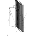
- FIG. 1 An example of a method for measuring the average roughness height Rc and the average roughness RSm of the cross-section curve (measurement method 1 for the cross-section curve element) is shown with reference to FIG.
- the vertical baseline 12 is drawn at intervals of 5 ⁇ m.
- the points where the vertical baseline drawn from the reference line intersects the component [C] for the first time are plotted, and the line connecting the plotted points is defined as the cross-sectional curve 13.
- the obtained cross-section curve 13 is subjected to a filtering process based on JIS B0601 (2001), and the roughness average height Rc and the roughness average length RSm of the cross-section curve 13 are calculated.
- the resin region containing [B] and the resin region containing [C] form a layer and are adjacent to each other to form the boundary surface from the viewpoint of exhibiting excellent mechanical properties.
- the basis weight of the thermoplastic resin of the component [C] is preferably 10 g / m 2 or more.
- a sufficient thickness for exhibiting excellent bonding strength can be obtained, which is preferable.
- the upper limit is not particularly limited, but it is preferably 500 g / m 2 or less because the amount of the thermoplastic resin does not become too large as compared with the reinforcing fiber and a laminated body having excellent specific strength and specific elastic modulus can be obtained.
- the basis weight refers to the mass (g) of the component [C] contained in 1 m 2 of the prepreg.
- the prepreg of the present invention preferably has a reinforcing fiber amount of 30 to 2,000 g / m 2 per unit area.
- the amount of the reinforcing fibers is 30 g / m 2 or more, the number of laminated fibers for obtaining a predetermined thickness at the time of molding the laminate can be reduced, and the work is easy to be simplified.
- the amount of reinforcing fibers is 2,000 g / m 2 or less, the drape property of the prepreg is likely to be improved.
- the reinforcing fiber mass content of the prepreg of the present invention is preferably 30 to 90% by mass, more preferably 35 to 85% by mass, and further preferably 40 to 80% by mass.
- the range may be a combination of any of the above upper limits and any of the lower limits.
- the laminate of the present invention satisfies the following forms.
- a layer containing the components [A], [C] and [D] is included, in which the average epoxy value of all epoxy resins is 2.0 meq. / G or more, 5.0 meq. It is a cured product of an epoxy resin having a value of / g or less, and there is a reinforcing fiber of [A] contained in both resin regions across the boundary surface between the resin region containing [C] and the resin region containing [D]. ..
- the component [D] used in the present invention is a cured epoxy resin, and the average epoxy value of all epoxy resins is 2.0 meq. / G or more, 5.0 meq. It is a cured product of an epoxy resin having a value of / g or less.
- the epoxy value is calculated as described above.
- a plurality of components [A] 6 are present on the boundary surface 10.
- the component [A] 6 on the boundary surface 10 is in contact with both the resin region 7 including the component [C] and the resin region 8 including the component [D].
- the state in which the component [C] and the component [D] are in contact with each other around the reinforcing fiber can be said to be a state in which the reinforcing fiber is "included in both resin regions across the boundary surface".
- the laminate of the present invention when viewed in a plan view, it is perpendicular to the plane direction of the laminate regardless of whether it is clockwise or counterclockwise with respect to the fiber direction of any [A] contained in both resin regions. Observation obtained by cutting at a 45-degree angle from a different viewpoint, perpendicular to the plane of the laminate containing [A] existing across both resin regions, that is, perpendicular to the plane direction of the laminate.
- the roughness average length RSm defined by JIS B0601 (2001) of the cross-sectional curve formed by the interface between the two resin regions in close contact is 100 ⁇ m or less, and the roughness average height Rc is 3.5 ⁇ m or more. Is preferable.
- the roughness average height Rc is more preferably 10 ⁇ m or more.
- the lower limit of RSm and the upper limit of Rc are not particularly limited, but RSm is preferably 15 ⁇ m or more, and Rc is preferably 100 ⁇ m or less from the viewpoint of concern about a decrease in mechanical bonding force due to stress concentration.
- As a method for measuring the average roughness height Rc and the average roughness RSm of the cross-sectional curve it can be obtained by the above method in the same manner as the method for measuring the prepreg of the present invention.
- the resin region containing [C] and the resin region containing [D] form a layer and are adjacent to each other to form the boundary surface from the viewpoint of exhibiting excellent mechanical properties.
- Adjacent in a layered state is a state in which both continuous resin regions exist adjacent to each other as shown in FIG. 2 as an example, and is confirmed by observing a cross section obtained by cutting perpendicular to the plane direction of the laminate. can do.
- An epoxy resin containing 20 parts by mass or more and 50 parts by mass or less of a bisphenol type epoxy resin having an epoxy equivalent of 400 or more and 3000 or less with respect to 100 parts by mass of all the epoxy resins containing the component [D] of the present invention Since it is a cured product, a laminated body and a molded product having excellent impact bonding strength can be obtained, which is a preferable embodiment.
- a more preferable embodiment is a cured product of an epoxy resin containing 20 parts by mass or more and 50 parts by mass or less of a bisphenol type epoxy resin having an epoxy equivalent of 1000 or more and 3000 or less with respect to 100 parts by mass of all the epoxy resins contained. That is.
- a method for molding the laminate of the present invention for example, a press molding method, an autoclave molding method, a bagging molding method, a wrapping tape method, an internal pressure molding method, a hand lay-up method, a filament winding method, a pull-fusion method, a resin -It can be manufactured by a molding method such as an injection molding method or a resin transfer molding method.
- the laminate of the present invention can be produced by laminating the above-mentioned prepreg of the present invention alone or together with other prepregs to form at least a part of the prepreg, and pressing and heating to cure the prepreg. ..
- a method of applying heat and pressure for example, a press molding method, an autoclave molding method, a bagging molding method, a wrapping tape method, an internal pressure molding method and the like are adopted.
- the thermoplastic resin of the component [C] is present on the surface or between the layers. It is preferred that the component [C] is present both on the surface and between the layers. Due to the presence of the thermoplastic resin of the component [C] on the surface of the laminate, the laminate of the present invention can be bonded to the same or different members through the component [C] by welding. When the thermoplastic resin component [C] between the layers of the laminate are present, excellent interlaminar fracture toughness (G IC and G IIC) is obtained.
- a member that is, a member (adhesion material) of the same type and / or a different type as the member constituting the laminate is present on the surface of the laminate by some heating means [C].
- members include members made of thermoplastic resin and members made of metal material.
- the member made of a thermoplastic resin may contain reinforcing fibers, fillers, and the like.
- the integration method is not particularly limited, and examples thereof include heat welding, vibration welding, ultrasonic welding, laser welding, resistance welding, induction welding, insert injection molding, and outsert injection molding.
- the strength of the joint portion of the integrated member is preferably 25 MPa or more, more preferably 28 MPa or more, when the tensile shear joint strength measured based on ISO4587: 1995 (JIS K6850 (1994)) is 25 MPa or more.
- the out-of-plane tensile joint strength measured based on ASTM D7291-07 is preferably 35 MPa or more, more preferably 40 MPa or more.
- the impact bonding strength was measured according to JIS K6855 (1994) is preferably as long as 6 kJ / m 2 or more, more preferably 9 kJ / m 2 or more. The higher the joint strength, the more preferable, and the upper limit is not particularly limited.
- the tensile shear joint strength is 200 MPa
- the out-of-plane tensile joint strength is 300 MPa
- the impact joint strength is 50 kJ / m 2. Is the upper limit.
- the unit "parts" of the composition ratio means parts by mass unless otherwise specified. Unless otherwise specified, various characteristics were measured in an environment with a temperature of 23 ° C. and a relative humidity of 50%.
- Component [C] Thermoplastic resin
- PA6 Polyamide 6 ("Amylan” (registered trademark) CM1007 (manufactured by Toray Industries, Inc., melting point 225 ° C.))
- 120 g / m 2 film PP: Polypropylene (" A film having a grain size of 120 g / m 2 made of "UMEX” (registered trademark) 1010 (manufactured by Sanyo Chemical Industries, Ltd., melting point 142 ° C.).
- -PEs Polyester ("Hytrel” (registered trademark) 2551 (manufactured by Toray DuPont Co., Ltd., melting point 164 ° C.)) with a basis weight of 120 g / m 2 ).
- -PPS Polyphenylene sulfide ("Trelina” (registered trademark) A670T05 (manufactured by Toray Industries, Inc., melting point 278 ° C.), 120 g / m 2 film with a mesh size)
- -PEEK Polyetheretherketone (PEEK 450G (manufactured by Victrex), A 120 g / m 2 film having a melting point of 343 ° C.).
- Epoxy resin / bisphenol A type epoxy resin (“jER” (registered trademark) 825, manufactured by Mitsubishi Chemical Co., Ltd.) Epoxy equivalent: 175 (g / eq.)) -Phenolic novolac type epoxy resin (“jER” (registered trademark) 154, manufactured by Mitsubishi Chemical Corporation) Epoxy equivalent: 178 (g / eq.)) -Bisphenol A type epoxy resin (“jER” (registered trademark) 1001, manufactured by Mitsubishi Chemical Corporation) Epoxy equivalent: 475 (g / eq.)) -Bisphenol A type epoxy resin (“jER” (registered trademark) 1004, manufactured by Mitsubishi Chemical Corporation) Epoxy equivalent: 925 (g / eq.)) -Bisphenol A type epoxy resin (“jER” (registered trademark) 1007, manufactured by Mitsubishi Chemical Co., Ltd.) Epoxy equivalent:
- thermoplastic resin ⁇ Measuring method of melting point of thermoplastic resin> The melting point of the thermoplastic resin was measured using a differential scanning calorimetry (DSC) based on JIS K7121 (2012). When multiple melting points were observed in a mixture or the like, the highest melting point was adopted as the melting point of the thermoplastic resin.
- DSC differential scanning calorimetry
- the prepreg was prepared by the following two methods.
- the components used in each example are as shown in Tables 2 and 3.
- Prepreg [I] A continuous reinforcing fiber sheet in which the reinforcing fibers (grain 193 g / m 2 ) of the component [A] are aligned in one direction is pulled out, and while running in one direction, the grain 120 g / consisting of the component [C] the resin sheet m 2 arranged in the continuous reinforcing fiber sheet, to melt the components by heating with an IR heater [C], is adhered to the continuous reinforcing fiber sheet entire one surface, the surface temperature of a component of [C]
- the fiber-reinforced resin intermediate was obtained by pressurizing with a nip roll kept below the melting point and cooling the impregnated fiber sheet.
- the epoxy resin composition according to the component [B] selected as shown in Tables 2 and 3 is coated on a release paper with a resin grain of 100 g / m 2 using a knife coater to prepare an epoxy resin film, and then the above.
- the epoxy resin film was superposed on the opposite surface of the intermediate body impregnated with the component [C], and the intermediate body was impregnated with the epoxy resin composition while being heated and pressed by a heat roll to obtain a prepreg [I].
- Prepreg [II] The epoxy resin composition according to the component [B] selected as shown in Tables 2 and 3 was coated on a release paper with a resin basis weight of 50 g / m 2 using a knife coater to prepare a resin film. This resin film is laminated on both sides of the reinforcing fibers (grain 193 g / m 2 ) of the component [A] aligned in one direction, and the carbon fibers are impregnated with the epoxy resin composition while heating and pressurizing using a heat roll. The prepreg [II] was obtained.
- Two pieces of the obtained laminate were cut into a shape having a width of 250 mm and a length of 92.5 mm with the 0 ° direction as the length direction of the test piece, and dried in a vacuum oven for 24 hours. After that, two panels cut into a shape having a width of 250 mm and a length of 92.5 mm were superposed with the 0 ° direction as the length direction and the width as 25 mm ⁇ the length as 12.5 mm, and the heat of the component [C] used was used. A pressure of 3 MPa was applied at a temperature 20 ° C. higher than the melting point of the plastic resin and the mixture was held for 1 minute to weld the overlapped surfaces to obtain an integrally molded product. A tab was adhered to the obtained integrally molded product in accordance with ISO4587: 1995 (JIS K6850 (1994)), and the tab was cut to a width of 25 mm to obtain a desired test piece.
- test piece was dried in a vacuum oven for 24 hours, and the tensile shear bond strength was measured at an ambient temperature of 23 ° C. based on ISO4587: 1995 (JIS K6850 (1994)). Based on the measurement results, the test pieces were as follows. Evaluated to. The results are shown in the table. 28 MPa or more: A 25 MPa or more and less than 28 MPa: B 20 MPa or more and less than 25 MPa: C Less than 20 MPa: D (failed).
- prepregs [I] two outermost layers on both sides of the preform are used as prepregs [I], and 103 prepregs [II] are sandwiched between them, and a total of 105 sheets are laminated so as to have the same reinforcing fiber direction, and both surface layers.
- a thermoplastic resin layer containing the component [C] was arranged so as to form a thermoplastic resin layer containing the component [C]
- a preform was prepared. That is, the surface impregnated with the component [C] of the prepreg [I] was arranged so as to be on the outside.
- Each of these two types of preforms is set in a press molding die, and if necessary, a jig or spacer is used to apply a pressure of 0.6 MPa with a press while maintaining this shape, and Table 2 or By heating under the molding conditions described in No. 3, two types of laminates having a thickness of about 10 mm and a thickness of about 20 mm were obtained.
- the existing position of the component [C] is the surface of the laminated body.
- the obtained laminate having a thickness of about 10 mm was cut into a square shape having a width of 250 mm and a length of 25 mm with the axial direction of the reinforcing fibers as the length direction of the test piece. Further, the obtained laminate having a thickness of about 20 mm was cut into a square shape having a width of 250 mm and a length of 45 mm with the axial direction of the reinforcing fibers as the length direction of the test piece, and the obtained two panels were evacuated. It was dried in the oven for 24 hours. After that, the two panels are laminated in the same reinforcing fiber axial direction, and held for 1 minute by applying a pressure of 3 MPa at a temperature 20 ° C. higher than the melting point of the thermoplastic resin of the component [C] used. As a result, the joint surfaces were welded to obtain an integrally molded product. The obtained integrally molded product was cut to a width of 25 mm to obtain a target test piece.
- the obtained test piece was dried in a vacuum oven for 24 hours, and the impact bonding strength was measured based on JIS K6855 (1994) with the surface orthogonal to the reinforcing fiber axial direction as the surface to be impacted, and based on the measurement results.
- the evaluation was as follows. The results are shown in the table. 9kJ / m 2 or more: A 6kJ / m 2 or more and less than 9kJ / m 2 : B 3kJ / m 2 or more and less than 6kJ / m 2 : C Less than 3kJ / m 2 : D (failed).
- the obtained reinforcing fiber composite material plate was cut into two squares having a width of 250 mm and a length of 125 mm with the reinforcing fiber shaft in the length direction of the test piece, and dried in a vacuum oven for 24 hours. After that, the two panels are laminated in the same reinforcing fiber axial direction, and held for 1 minute by applying a pressure of 3 MPa at a temperature 20 ° C. higher than the melting point of the thermoplastic resin of the component [C] used. As a result, the joint surfaces were welded to obtain an integrally molded product.
- the obtained integrally molded product was ground into a spool shape having an outer diameter of 25 mm, an inner diameter of 19 mm, and a gauge length of 6.4 mm to obtain a target test piece.
- the obtained test piece was dried in a vacuum oven for 24 hours, the out-of-plane tensile joint strength was measured based on ASTM D7291-07, and the evaluation was made as follows based on the measurement result. The results are shown in the table. 40 MPa or more: A 35 MPa or more and less than 40 MPa: B 30 MPa or more and less than 35 MPa: C Less than 30 MPa: D (failed).
- a rectangular test piece having a length of 150 mm and a width of 20 mm was cut out with the reinforcing fiber shaft as the length direction of the test piece, and dried in a vacuum oven at 60 ° C. for 24 hours.
- Examples 1 to 14 In Examples 1 to 14, the method described in (1) the method described in the method for measuring the tensile shear joint strength, (2) the method described in the method for measuring the impact joint strength, and (3) the method described in the method for measuring the out-of-plane tensile joint strength. A laminate was prepared by the method of.
- Example 1 As shown in Table 2, the average epoxy value of the component [B] was 3.9 meq. It was shown that by using the / g epoxy resin, the impact bonding strength and the out-of-plane tensile bonding strength were excellent as an integrally molded product as compared with Comparative Examples 1 and 2 shown in Table 3.
- Examples 1 to 6 As shown in Table 1, in Examples 1 to 6, epoxy resins having different average epoxy valences were used. As shown in Table 2, when the average epoxy value is high, the impact bonding strength tends to decrease slightly, and when the average epoxy value is low, the out-of-plane tensile bonding strength tends to decrease slightly. In the range of the average epoxy value in 6, all showed excellent various bonding strengths.
- Example 1 and Example 7 As shown in Table 1, a curing agent different from that in Example 1 was used in Example 7, but as shown in Table 2, various excellent bonding strengths were exhibited as in Example 1.
- Example 1 As shown in Table 1, in Example 8, it was prepared in the same manner as in Example 1 except that a viscosity modifier was not used. As shown in Table 2, Example 8 showed excellent joint strengths as in Example 1.
- Example 1 and Examples 9 and 10 As shown in Table 2, when reinforcing fibers having different strand tensile strengths were used in Example 9 and Example 10, the higher the strand tensile strength, the higher the tensile shear joint strength and the out-of-plane tension as compared with Example 1. The joint strength was improved and showed favorable characteristics.
- Example 1 and Comparative Example 3 a film of polyamide 6 (“Amiran” (registered trademark) CM1007 (manufactured by Toray Industries, Inc.)) having a film texture of 50 g / m 2 was attached to both sides of the reinforcing fiber sheets arranged in a unidirectional plane.
- the prepreg was heated and pressurized at 250 ° C. to obtain a prepreg having a reinforced carbon fiber grain of 193 g / m 2 .
- the obtained prepreg was cut to a predetermined size and laminated in a configuration of [0 ° / 90 °] 2s for evaluation of tensile shear joint strength.
- Example 15 it was prepared a laminate by the method described in the measurement method (4) interlaminar fracture toughness (G IC and G IIC).
- the above prepreg [I] is cut to a predetermined size, and a total of 20 prepregs are laminated with the side where the component [C] is present facing upward so that the same reinforcing fiber direction is obtained, and the central 10 sheets are laminated.
- a release film for introducing a preliminary crack was sandwiched between the eyes and the eleventh sheet to prepare a preform.
- Comparative Example 4 the prepreg [II] (without the component [C]) was cut to a predetermined size, laminated in the same manner as in Example 15, and the release film was sandwiched to obtain a preform.
- Comparative Example 5 polyamide particles (SP-500, manufactured by Toray Industries, Inc.) were placed on one side surface of the prepreg [II] (not containing the component [C]) cut to a predetermined size per prepreg unit area. After uniformly spraying so that the amount of particles was 7 g / m 2 , the particles were laminated in the same manner as in Example 15 and a release film was sandwiched to obtain a preform.
- SP-500 manufactured by Toray Industries, Inc.
Landscapes
- Chemical & Material Sciences (AREA)
- Engineering & Computer Science (AREA)
- Materials Engineering (AREA)
- Polymers & Plastics (AREA)
- Manufacturing & Machinery (AREA)
- Health & Medical Sciences (AREA)
- Chemical Kinetics & Catalysis (AREA)
- Medicinal Chemistry (AREA)
- Inorganic Chemistry (AREA)
- Organic Chemistry (AREA)
- Physics & Mathematics (AREA)
- Mathematical Physics (AREA)
- Composite Materials (AREA)
- Mechanical Engineering (AREA)
- Reinforced Plastic Materials (AREA)
- Laminated Bodies (AREA)
Abstract
Description
[A]強化繊維
[B]エポキシ樹脂
[C]熱可塑性樹脂
さらに、本発明の積層体は、次の構成を有する積層体である。すなわち、次の構成要素[A]、[C]及び[D]を含む層が含まれ、[D]に含まれる全てのエポキシ樹脂の平均エポキシ価が2.0meq./g以上、5.0meq./g以下であり、[C]を含む樹脂領域と[D]を含む樹脂領域との境界面をまたいで両樹脂領域に含まれる[A]の強化繊維が存在する積層体。
[A]強化繊維
[C]熱可塑性樹脂
[D]エポキシ樹脂硬化物
平均エポキシ価(meq./g)=(エポキシ樹脂1の質量部数/エポキシ樹脂1のエポキシ当量+エポキシ樹脂2の質量部数/エポキシ樹脂2のエポキシ当量)/(エポキシ樹脂1の質量部数+エポキシ樹脂2の質量部数)×1000
ここでエポキシ当量は、JIS K7236(2009)に記載の方法によって求めた値を指す。含まれる全てのエポキシ樹脂の平均エポキシ価が、2.0meq./g以上、5.0meq./g以下であることで、積層体や成形品として、優れた引張せん断接合強度、面外引張接合強度および衝撃接合強度を示す。さらに、含まれる全てのエポキシ樹脂の平均エポキシ価が、2.5meq./g以上、4.0meq./g以下であることが、より好ましい態様である。上記の上限のいずれかと下限のいずれかとの組み合わせによる範囲であってもよい。
硬化度(%)=((エポキシ樹脂を含む組成物の硬化前の発熱量)-(エポキシ樹脂の硬化物の発熱量))/(エポキシ樹脂を含む組成物の硬化前の発熱量)×100
本発明における構成要素[D]のエポキシ樹脂硬化物は、構成要素[B]のエポキシ樹脂を、加熱硬化することにより得ることができる。積層体に含まれる構成要素[D]の硬化の判定について、積層体を不活性ガス雰囲気下、昇温速度10℃/分にて示差走査熱量分析を行った際に発熱反応として現れるピークの面積(残存発熱)が、50J/g以下であれば、実質的に硬化物であると判定することができる。もしくは、硬化前のエポキシ樹脂組成物を特定できる場合は、上式により硬化度を求めて、90%以上であれば硬化物としてよい。本発明のプリプレグを用いる場合は、エポキシ樹脂は構成要素[B]に対応する。本発明の積層体は、必ずしもプリプレグを経由したものではなく、後述するレジントランスファーモールディング法などで作成されてもよい。
以下に示す構成要素[A]、[B]、[C]及び[D]を用いた。それぞれの実施例および比較例で用いた構成要素は、表1から3に示すとおりである。
・T800:炭素繊維(“トレカ(登録商標)”T800S-24K、東レ(株)製、ストランド引張強度:5.9GPa)
・T1100:炭素繊維(“トレカ(登録商標)”T1100G-24K、東レ(株)製、ストランド引張強度:7.0GPa)
・T700:炭素繊維(“トレカ(登録商標)”T700S-24K、東レ(株)製、ストランド引張強度:4.9GPa)。
・PA6:ポリアミド6(“アミラン”(登録商標)CM1007(東レ(株)製、融点225℃))からなる目付120g/m2のフィルム
・PP:ポリプロピレン(“ユーメックス”(登録商標)1010(三洋化成(株)社製、融点142℃))からなる目付120g/m2のフィルム)。
・PEs:ポリエステル(“ハイトレル”(登録商標)2551(東レデュポン(株)社製、融点164℃))からなる目付120g/m2のフィルム)。
・PPS:ポリフェニレンスルフィド(“トレリナ”(登録商標)A670T05(東レ(株)社製、融点278℃)からなる目付120g/m2のフィルム
・PEEK:ポリエーテルエーテルケトン(PEEK 450G(Victrex社製、融点343℃)からなる目付120g/m2のフィルム。
表1に記載の各具体例のエポキシ樹脂組成物を、以下の化合物を用いて作製した。
(1)エポキシ樹脂
・ビスフェノールA型エポキシ樹脂(“jER”(登録商標)825、三菱ケミカル(株)製)エポキシ当量:175(g/eq.))
・フェノールノボラック型エポキシ樹脂(“jER”(登録商標)154、三菱ケミカル(株)製)エポキシ当量:178(g/eq.))
・ビスフェノールA型エポキシ樹脂(“jER”(登録商標)1001、三菱ケミカル(株)製)エポキシ当量:475(g/eq.))
・ビスフェノールA型エポキシ樹脂(“jER”(登録商標)1004、三菱ケミカル(株)製)エポキシ当量:925(g/eq.))
・ビスフェノールA型エポキシ樹脂(“jER”(登録商標)1007、三菱ケミカル(株)製)エポキシ当量:1975(g/eq.))。
(2)硬化剤
・4,4’-ジアミノジフェニルスルホン(セイカキュアS、和歌山精化工業(株)製)
・ジシアンジアミド(DICY7、三菱ケミカル(株)製)。
(3)硬化触媒
3-(3,4-ジクロロフェニル)1,1-ジメチルウレア(DCMU99、保土ヶ谷化学工業(株)製)。
(4)粘度調整剤
・ポリビニルホルマール(“ビニレック”(登録商標)K、JNC(株)製)。
(5)エポキシ樹脂組成物の調製方法
混練装置中に、表1に記載のエポキシ樹脂および粘度調整剤を投入し、加熱混練を行い、粘度調整剤を溶解させた(ただし、粘度調整剤を加えない場合もある)。次いで、混練を続けたまま100℃以下の温度まで降温させ、表1に記載の硬化剤および硬化触媒から適宜選択されたものを加えて撹拌し、B-1~B-10までのエポキシ樹脂組成物を得た。
上記の方法で調製したエポキシ樹脂組成物をモールドに注入し、熱風乾燥機中で30℃から速度1.5℃/分で表1に記載の硬化温度まで昇温し、表1に記載の硬化時間加熱硬化した後、30℃まで速度2.5℃/分で降温して、厚さ2mmの板状のエポキシ樹脂硬化物を作製した。構成要素[B]エポキシ樹脂の硬化物であり、構成要素[D]エポキシ樹脂硬化物である。得られたエポキシ樹脂硬化物より、以下の方法にて、表1に記載の各具体例の評価を実施した。
上記の方法で作製した板状の樹脂硬化物から、長さ60mm、幅10mmの矩形状の試験片を切り出し、試験片を60℃真空オーブン中で24時間乾燥させ、材料万能試験機(インストロン・ジャパン(株)製、“インストロン”(登録商標)5565型P8564)を用い、試験速度2.5mm/分、支点間距離32mmで3点曲げ試験を行い、JIS K7171(1994)に従い、曲げ破断歪および曲げ強度を求めた。
熱可塑性樹脂の融点は、JIS K7121(2012)に基づいて、示差走査熱量計(DSC)を用いて測定した。混合物などで融点が複数観測される場合は、最も高い融点をその熱可塑性樹脂の融点として採用した。
プリプレグは、以下の2種の方法により作製した。各例で使用した構成要素は表2,3記載のそれぞれのとおりである。
構成要素[A]の強化繊維(目付193g/m2)を、一方向に整列させた連続した状態の強化繊維シートを引き出し、一方向に走行させつつ、構成要素[C]からなる目付120g/m2の樹脂シートを連続強化繊維シート上に配置して、IRヒータで加熱して構成要素[C]を溶融し、連続強化繊維シート片面全面に付着させ、表面温度が構成要素[C]の融点以下に保たれたニップロールで加圧して、強化繊維シートに含浸したものを冷却させて繊維強化樹脂中間体を得た。表2,3記載のとおり選定した構成要素[B]に係るエポキシ樹脂組成物を、ナイフコーターを用いて樹脂目付100g/m2で離型紙上にコーティングし、エポキシ樹脂フィルムを作製した後、上記中間体における構成要素[C]を含浸させた反対の表面に上記エポキシ樹脂フィルムを重ね、ヒートロールにより加熱加圧しながらエポキシ樹脂組成物を中間体に含浸させ、プリプレグ[I]を得た。
表2,3記載のとおり選定した構成要素[B]に係るエポキシ樹脂組成物を、ナイフコーターを用いて樹脂目付50g/m2で離型紙上にコーティングし、樹脂フィルムを作製した。この樹脂フィルムを、一方向に引き揃えた構成要素[A]の強化繊維(目付193g/m2)の両側に重ね合せてヒートロールを用い、加熱加圧しながらエポキシ樹脂組成物を炭素繊維に含浸させ、プリプレグ[II]を得た。
(1)引張せん断接合強度の測定方法
上記で作製したプリプレグ[I]および[II]を所定の大きさにカットし、プリプレグ[I]を2枚とプリプレグ[II]を6枚得た。強化繊維の軸方向を0°とし、軸直交方向を90°と定義して、[0°/90°]2s(記号sは、鏡面対称を示す)で積層し、プリフォームを作製した。このときプリフォームの両面それぞれの最外層の2枚はプリプレグ[I]となるように積層した。すなわち、プリプレグ[I]2枚がプリプレグ[II]6枚を挟み込むように積層した。プリフォームの両の表層が、構成要素[C]を含む熱可塑性樹脂層となるように配置した。すなわち、プリプレグ[I]の構成要素[C]を含浸させた面が外側になるように配置した。このプリフォームをプレス成形金型にセットし、必要に応じ、治具やスペーサーを使用して、この形状を維持させたまま、プレス機で0.6MPaの圧力をかけ、表2,3に記載の条件で加温することで、積層体を得た。構成要素[C]の存在位置は積層体の表面である。
28MPa以上:A
25MPa以上28MPa未満:B
20MPa以上25MPa未満:C
20MPa未満:D(不合格)。
上記で作製したプリプレグ[I]および[II]を所定の大きさにカットし、プリフォームの両面それぞれの最外層の2枚はプリプレグ[I]として、間にプリプレグ[II]50枚を挟んで、全て同一の強化繊維方向となるよう計52枚積層し、プリフォームを作製した。このとき、プリフォームの両の表層が構成要素[C]を含む熱可塑性樹脂層となるように配置した。すなわち、プリプレグ[I]の構成要素[C]を含浸させた面が外側になるように配置した。同じく、プリフォームの両面それぞれの最外層の2枚はプリプレグ[I]として、間にプリプレグ[II]103枚を挟んで、同一の強化繊維方向となるよう計105枚積層して、両の表層が構成要素[C]を含む熱可塑性樹脂層となるように配置して、プリフォームを作製した。すなわち、プリプレグ[I]の構成要素[C]を含浸させた面が外側になるように配置した。この2種のプリフォームをそれぞれプレス成形金型にセットし、必要に応じて治具やスペーサーを使用して、この形状を維持させたままプレス機で0.6MPaの圧力をかけ、表2または3に記載の成形条件で加温することで、厚み約10mmと厚み約20mmの2種の積層体を得た。構成要素[C]の存在位置は積層体の表面である。
9kJ/m2以上:A
6kJ/m2以上9kJ/m2未満:B
3kJ/m2以上6kJ/m2未満:C
3kJ/m2未満:D(不合格)。
上記で作製したプリプレグ[I]および[II]を所定の大きさにカットし、プリフォームの両面それぞれの最外層の2枚はプリプレグ[I]として、間にプリプレグ[II]73枚を挟んで、全て同一の強化繊維方向となるよう計75枚積層し、プリフォームを作製した。このとき両面それぞれの最外層の2枚はプリプレグ[I]となるように積層し、プリフォームの両の表層が、構成要素[C]を含む熱可塑性樹脂層となるように配置した。このプリフォームをプレス成形金型にセットし、必要に応じ、治具やスペーサーを使用して、この形状を維持させたまま、プレス機で0.6MPaの圧力をかけ、表2または3に記載の成形条件で加温することで、積層体を得た。構成要素[C]の存在位置は積層体の表面である。
40MPa以上:A
35MPa以上40MPa未満:B
30MPa以上35MPa未満:C
30MPa未満:D(不合格)。
上記で作製したプリプレグ[I]を所定の大きさにカットし、同一の強化繊維方向となるよう、全てのプリプレグを構成要素[C]が存在する面を上向きにして、計20枚積層した。このとき、中央の10枚目と11枚目の間の位置に予備亀裂導入のための離型フィルムを挟み込み、プリフォームを作製した。このプリフォームをプレス成形金型にセットし、必要に応じ、治具やスペーサーを使用して、この形状を維持させたまま、プレス機で0.6MPaの圧力をかけ、表2または3に記載の成形条件で、積層体を得た。構成要素[C]の存在位置は積層体の層間および片側の表面である。
上記で作製したプリプレグ[I]または積層体を用いる。図1で示す通り、プリプレグの場合においては、前記両樹脂領域に含まれる任意の[A]の繊維方向4に対し、プリプレグの平面視、すなわちプリプレグ平面方向に対し垂直な始点における45度の角度にて、プリプレグ平面方向に対し垂直にカットした観察断面5において、光学顕微鏡を用いて、1000倍の画像を撮影した。得られた画像中の任意の500μm四方の観察範囲において、前記断面曲線要素の測定方法1により得られる断面曲線要素のJIS B0601(2001)で定義される、粗さ平均長さRSmおよび粗さ平均高さRcを測定した。積層体の場合も同様である。
実施例1~14では、(1)引張せん断接合強度の測定方法に記載の方法、(2)衝撃接合強度の測定方法に記載の方法、および(3)面外引張接合強度の測定方法に記載の方法で積層体を作製した。
実施例1では、表2に記載の通り、構成要素[B]として平均エポキシ価が3.9meq./gのエポキシ樹脂を用いることで、表3に記載の比較例1および比較例2と比べ、一体化成形品として、衝撃接合強度および面外引張接合強度が優れていることを示した。
表1に記載の通り、実施例1~6では、平均エポキシ価の異なるエポキシ樹脂を用いた。表2に示す通り、平均エポキシ価が高くなると、衝撃接合強度が若干低下する傾向を示し、平均エポキシ価が低くなると、面外引張接合強度が若干低下する傾向を示したが、実施例1~6での平均エポキシ価の範囲では、いずれも優れた各種接合強度を示した。
表1に記載の通り、実施例7では実施例1と異なる硬化剤を使用したが、表2に記載の通り、実施例1と同様に優れた各種接合強度を示した。
表1に記載の通り、実施例8では、粘度調整剤を用いないこと以外は、実施例1と同様に作製した。表2に記載の通り、実施例8は実施例1と同様に優れた各種接合強度を示した。
表2に記載の通り、実施例9および実施例10では、ストランド引張強度の異なる強化繊維を用いたところ、実施例1と比較すると、ストランド引張強度が高いほど、引張せん断接合強度および面外引張接合強度が向上し、好ましい特性を示した。
表2に記載の通り、実施例11~14では、実施例1と異なる構成要素[C]を用いたが、実施例1と同様に優れた各種接合強度を示した。
比較例3では、一方向平面状に配列させた強化繊維シートの両面に、フィルム目付50g/m2のポリアミド6(“アミラン”(登録商標)CM1007(東レ(株)製))のフィルムを貼り付け、250℃で加熱加圧して、強化炭素繊維目付193g/m2のプリプレグを得た。得られたプリプレグを、所定のサイズにカットし、引張せん断接合強度評価用に、[0°/90°]2sの構成で積層した。衝撃接合強度評価用には、同一の強化繊維方向となるよう、計52枚積層したプリプレグおよび計105枚積層したプリプレグの2種を用いた。面外引張接合強度評価用には、同一の強化繊維方向となるよう75枚積層した。得られた積層後のそれぞれのプリプレグを、プレス機で3MPaの圧力をかけ、250℃で10分間加温することで、それぞれの積層体板を得た。得られた積層体より、実施例に記載の方法で引張せん断接合強度、衝撃接合強度および面外引張接合強度を測定した。表3に示す通り、比較例3の積層体板はエポキシ樹脂非含有であるため、実施例1に比べて面外引張強度が低く、構造材料として十分な特性を示さなかった。
実施例15では、(4)層間破壊靱性値(GICおよびGIIC)の測定方法に記載の方法で積層体を作成した。上記プリプレグ[I]を所定の大きさにカットし、同一の強化繊維方向となるよう、全てのプリプレグを構成要素[C]が存在する面を上向きにして計20枚積層し、中央の10枚目と11枚目の間の位置に予備亀裂導入のための離型フィルムを挟み込み、プリフォームを作製した。比較例4では、プリプレグ[II](構成要素[C]非含有)を所定の大きさにカットし、実施例15と同じ方法で積層し、離型フィルムを挟み込み、プリフォームを得た。比較例5では、所定の大きさにカットしたプリプレグ[II](構成要素[C]非含有)の片側表面に、ポリアミド粒子(SP-500、東レ(株)製)を、プリプレグ単位面積あたりの粒子量が7g/m2となるよう均一に散布したのち、実施例15と同じ方法で積層し、離型フィルムを挟み込み、プリフォームを得た。実施例15および比較例4,5とも、得られたプリフォームを、プレス機で0.6MPaの圧力をかけ、135℃で120分間加温することで、積層体を得た後、上記実施例に記載の方法で、層間破壊靱性値(GICおよびGIIC)を評価した。表2および3に記載の通り、構成要素[C]を積層体の層間に含む実施例15は、構成要素[C]非含有の比較例4および熱可塑性樹脂を異なる形態として含む比較例5に比べ、優れた層間破壊靱性値を示した。


2:構成要素[A]
3:構成要素[C]および構成要素[B]または構成要素[C]および構成要素[D]
4:任意の繊維束の軸方向
5:観察断面
6:構成要素[A]
7:構成要素[C]を含む樹脂領域
8:構成要素[B]を含む樹脂領域または構成要素[D]を含む樹脂領域
9:観察画像
10:境界面
11:基準線
12:垂基線
13:断面曲線
Claims (19)
- 次の構成要素[A]、[B]及び[C]を含むプリプレグであって、
[B]に含まれる全てのエポキシ樹脂の平均エポキシ価が2.0meq./g以上、5.0meq./g以下であり、プリプレグの表面に[C]が存在しており、
[B]を含む樹脂領域と[C]を含む樹脂領域との境界面をまたいで両樹脂領域に含まれる[A]の強化繊維が存在するプリプレグ。
[A]強化繊維
[B]エポキシ樹脂
[C]熱可塑性樹脂 - 前記プリプレグの平面視において、前記両樹脂領域に含まれる任意の[A]の繊維方向に対し45度異なる角度の方向から、前記[A]を含むプリプレグ平面に垂直な断面を得た場合に、前記断面において、両樹脂領域の密着する境界面が形成する断面曲線の、JIS B0601(2001)で定義される粗さ平均長さRSmが100μm以下であり、粗さ平均高さRcが3.5μm以上である、請求項1に記載のプリプレグ。
- 前記[B]を含む樹脂領域と[C]を含む樹脂領域がそれぞれ層状をなして隣接することにより前記境界面を形成している、請求項1または2に記載のプリプレグ。
- 構成要素[B]に含まれる全てのエポキシ樹脂の平均エポキシ価が2.5meq./g以上、4.0meq./g以下である、請求項1から3のいずれかに記載のプリプレグ。
- 構成要素[B]は、含有される全てのエポキシ樹脂100質量部に対して、エポキシ当量400以上、3000以下のビスフェノール型エポキシ樹脂を20質量部以上、50質量部以下含む、請求項1から4のいずれかに記載のプリプレグ。
- 構成要素[B]は、含有される全てのエポキシ樹脂100質量部に対して、エポキシ当量1000以上、3000以下のビスフェノール型エポキシ樹脂を20質量部以上、50質量部以下含む、請求項5に記載のプリプレグ。
- 構成要素[B]は、硬化度が90%以上の状態での曲げ破断歪が8%以上である、請求項1から6のいずれかに記載のプリプレグ。
- 構成要素[A]には、ストランド引張強度が5.5GPa以上の炭素繊維が含まれる、請求項1から7のいずれかに記載のプリプレグ。
- 前記粗さ平均高さRcが10μm以上である、請求項1から8のいずれかに記載のプリプレグ。
- 次の構成要素[A]、[C]及び[D]を含む層が含まれる積層体であって、
[D]が全てのエポキシ樹脂の平均エポキシ価が2.0meq./g以上、5.0meq./g以下であるエポキシ樹脂の硬化物であり、
[C]を含む樹脂領域と[D]を含む樹脂領域との境界面をまたいで両樹脂領域に含まれる[A]の強化繊維が存在する積層体。
[A]強化繊維
[C]熱可塑性樹脂
[D]エポキシ樹脂硬化物 - 前記積層体の平面視において、前記両樹脂領域に含まれる任意の[A]の繊維方向に対し45度異なる角度の方向から、前記[A]を含む積層体の平面に垂直な断面を得た場合に、前記断面において、両樹脂領域の密着する境界面が形成する断面曲線の、JIS B0601(2001)で定義される粗さ平均長さRSmが100μm以下であり、粗さ平均高さRcが3.5μm以上である、請求項10に記載の積層体。
- 前記[C]を含む樹脂領域と[D]を含む樹脂領域がそれぞれ層状をなして隣接することにより前記境界面を形成している、請求項10または11に記載の積層体。
- 表面に構成要素[C]が存在する、請求項10から12のいずれかに記載の積層体。
- 層間に構成要素[C]が存在する、請求項10から13のいずれかに記載の積層体。
- 構成要素[D]は、含有される全てのエポキシ樹脂100質量部に対して、エポキシ当量1000以上、3000以下のビスフェノール型エポキシ樹脂を20質量部以上、50質量部以下含むエポキシ樹脂の硬化物である、請求項10から14のいずれかに記載の積層体。
- 前記粗さ平均高さRcが10μm以上である、請求項10から15のいずれかに記載の積層体。
- 構成要素[A]には、ストランド引張強度が5.5GPa以上の炭素繊維が含まれる、請求項10から16のいずれかに記載の積層体。
- 請求項1から9のいずれかに記載のプリプレグの硬化物が少なくとも一部の層を構成する積層体である、請求項13または14に記載の積層体。
- 別の部材が、構成要素[C]の面に接合することにより、請求項13から18のいずれかに記載の積層体と一体化されてなる、成形品。
Priority Applications (4)
| Application Number | Priority Date | Filing Date | Title |
|---|---|---|---|
| EP20808920.1A EP3974466A4 (en) | 2019-05-23 | 2020-05-15 | PRE-IMPREGNATED, LAMINATED, AND MOLDED ARTICLE |
| JP2020542924A JP7615683B2 (ja) | 2019-05-23 | 2020-05-15 | プリプレグ、積層体および成形品 |
| CN202080036511.2A CN113825788B (zh) | 2019-05-23 | 2020-05-15 | 预浸料坯、层叠体及成型品 |
| US17/608,237 US12492289B2 (en) | 2019-05-23 | 2020-05-15 | Prepreg, laminate, and molding |
Applications Claiming Priority (4)
| Application Number | Priority Date | Filing Date | Title |
|---|---|---|---|
| JP2019097031 | 2019-05-23 | ||
| JP2019-097033 | 2019-05-23 | ||
| JP2019-097031 | 2019-05-23 | ||
| JP2019097033 | 2019-05-23 |
Publications (1)
| Publication Number | Publication Date |
|---|---|
| WO2020235485A1 true WO2020235485A1 (ja) | 2020-11-26 |
Family
ID=73459436
Family Applications (1)
| Application Number | Title | Priority Date | Filing Date |
|---|---|---|---|
| PCT/JP2020/019467 Ceased WO2020235485A1 (ja) | 2019-05-23 | 2020-05-15 | プリプレグ、積層体および成形品 |
Country Status (6)
| Country | Link |
|---|---|
| US (1) | US12492289B2 (ja) |
| EP (1) | EP3974466A4 (ja) |
| JP (1) | JP7615683B2 (ja) |
| CN (1) | CN113825788B (ja) |
| TW (1) | TWI864001B (ja) |
| WO (1) | WO2020235485A1 (ja) |
Cited By (2)
| Publication number | Priority date | Publication date | Assignee | Title |
|---|---|---|---|---|
| WO2022024939A1 (ja) * | 2020-07-27 | 2022-02-03 | 東レ株式会社 | 繊維強化プラスチック及び繊維強化プラスチックの製造方法 |
| WO2022107563A1 (ja) * | 2020-11-18 | 2022-05-27 | 東レ株式会社 | 繊維強化樹脂および一体化成形品 |
Families Citing this family (2)
| Publication number | Priority date | Publication date | Assignee | Title |
|---|---|---|---|---|
| JP7676777B2 (ja) * | 2019-12-11 | 2025-05-15 | 東レ株式会社 | プリプレグ、積層体および一体化成形品 |
| JPWO2021246466A1 (ja) * | 2020-06-03 | 2021-12-09 |
Citations (11)
| Publication number | Priority date | Publication date | Assignee | Title |
|---|---|---|---|---|
| JPH01104625A (ja) * | 1987-10-16 | 1989-04-21 | Toray Ind Inc | 複合材料 |
| JPH08259713A (ja) | 1995-03-22 | 1996-10-08 | Toray Ind Inc | プリプレグおよび繊維強化複合材料 |
| JPH08337707A (ja) * | 1995-04-12 | 1996-12-24 | Toray Ind Inc | エポキシ樹脂組成物、プリプレグおよび繊維強化複合材料 |
| JPH10138354A (ja) | 1996-11-08 | 1998-05-26 | Yamaha Corp | 炭素繊維強化樹脂成形物とその製造方法 |
| JP2003201388A (ja) * | 2002-01-08 | 2003-07-18 | Toray Ind Inc | エポキシ樹脂組成物、樹脂硬化物、プリプレグおよび繊維強化複合材料 |
| WO2004060658A1 (ja) * | 2002-12-27 | 2004-07-22 | Toray Industries, Inc. | 積層体、電磁波シールド成形品、および、それらの製造方法 |
| JP2012051989A (ja) * | 2010-08-31 | 2012-03-15 | Sumitomo Bakelite Co Ltd | プリプレグ、基板および半導体装置 |
| WO2018066600A1 (ja) * | 2016-10-04 | 2018-04-12 | 三菱ケミカル株式会社 | プリプレグ、プリプレグ積層体、および繊維強化複合材料 |
| WO2018117214A1 (ja) * | 2016-12-21 | 2018-06-28 | 三菱ケミカル株式会社 | 硬化性樹脂組成物、並びにこれを用いたフィルム、成形品、プリプレグ及び繊維強化プラスチック |
| JP2018161801A (ja) | 2017-03-27 | 2018-10-18 | 三菱ケミカル株式会社 | 接着構造部材 |
| JP2019038939A (ja) * | 2017-08-25 | 2019-03-14 | 東レ株式会社 | プリプレグおよび繊維強化複合材料 |
Family Cites Families (8)
| Publication number | Priority date | Publication date | Assignee | Title |
|---|---|---|---|---|
| CN101085865B (zh) * | 2002-12-27 | 2012-10-10 | 东丽株式会社 | 用于热结合的基材及用其制造层压品的方法 |
| WO2008013094A1 (fr) * | 2006-07-28 | 2008-01-31 | Toray Industries, Inc. | Article moulé et son procédé de fabrication |
| KR101569595B1 (ko) | 2010-09-28 | 2015-11-16 | 도레이 카부시키가이샤 | 에폭시 수지 조성물, 프리프레그 및 섬유 강화 복합 재료 |
| US20120108132A1 (en) * | 2010-10-28 | 2012-05-03 | General Electric Company | Composite Compositions |
| JP6094686B2 (ja) * | 2014-10-16 | 2017-03-15 | 三菱レイヨン株式会社 | 樹脂組成物およびそのプレス成形体 |
| JP6922493B2 (ja) * | 2017-07-11 | 2021-08-18 | 住友ゴム工業株式会社 | アイアンゴルフクラブ |
| JPWO2020255775A1 (ja) * | 2019-06-20 | 2020-12-24 | ||
| JP7231105B1 (ja) * | 2022-03-30 | 2023-03-01 | 東洋インキScホールディングス株式会社 | 蓄電デバイス包装材用接着剤、蓄電デバイス包装材、蓄電デバイス用容器及び蓄電デバイス |
-
2020
- 2020-05-15 WO PCT/JP2020/019467 patent/WO2020235485A1/ja not_active Ceased
- 2020-05-15 EP EP20808920.1A patent/EP3974466A4/en active Pending
- 2020-05-15 US US17/608,237 patent/US12492289B2/en active Active
- 2020-05-15 CN CN202080036511.2A patent/CN113825788B/zh active Active
- 2020-05-15 JP JP2020542924A patent/JP7615683B2/ja active Active
- 2020-05-22 TW TW109117059A patent/TWI864001B/zh active
Patent Citations (12)
| Publication number | Priority date | Publication date | Assignee | Title |
|---|---|---|---|---|
| JPH01104625A (ja) * | 1987-10-16 | 1989-04-21 | Toray Ind Inc | 複合材料 |
| JPH08259713A (ja) | 1995-03-22 | 1996-10-08 | Toray Ind Inc | プリプレグおよび繊維強化複合材料 |
| JPH08337707A (ja) * | 1995-04-12 | 1996-12-24 | Toray Ind Inc | エポキシ樹脂組成物、プリプレグおよび繊維強化複合材料 |
| JPH10138354A (ja) | 1996-11-08 | 1998-05-26 | Yamaha Corp | 炭素繊維強化樹脂成形物とその製造方法 |
| JP2003201388A (ja) * | 2002-01-08 | 2003-07-18 | Toray Ind Inc | エポキシ樹脂組成物、樹脂硬化物、プリプレグおよび繊維強化複合材料 |
| WO2004060658A1 (ja) * | 2002-12-27 | 2004-07-22 | Toray Industries, Inc. | 積層体、電磁波シールド成形品、および、それらの製造方法 |
| JP3906319B2 (ja) | 2002-12-27 | 2007-04-18 | 東レ株式会社 | 積層体、一体化成形品、および、それらの製造方法 |
| JP2012051989A (ja) * | 2010-08-31 | 2012-03-15 | Sumitomo Bakelite Co Ltd | プリプレグ、基板および半導体装置 |
| WO2018066600A1 (ja) * | 2016-10-04 | 2018-04-12 | 三菱ケミカル株式会社 | プリプレグ、プリプレグ積層体、および繊維強化複合材料 |
| WO2018117214A1 (ja) * | 2016-12-21 | 2018-06-28 | 三菱ケミカル株式会社 | 硬化性樹脂組成物、並びにこれを用いたフィルム、成形品、プリプレグ及び繊維強化プラスチック |
| JP2018161801A (ja) | 2017-03-27 | 2018-10-18 | 三菱ケミカル株式会社 | 接着構造部材 |
| JP2019038939A (ja) * | 2017-08-25 | 2019-03-14 | 東レ株式会社 | プリプレグおよび繊維強化複合材料 |
Non-Patent Citations (1)
| Title |
|---|
| See also references of EP3974466A4 |
Cited By (7)
| Publication number | Priority date | Publication date | Assignee | Title |
|---|---|---|---|---|
| WO2022024939A1 (ja) * | 2020-07-27 | 2022-02-03 | 東レ株式会社 | 繊維強化プラスチック及び繊維強化プラスチックの製造方法 |
| JPWO2022024939A1 (ja) * | 2020-07-27 | 2022-02-03 | ||
| US12409614B2 (en) | 2020-07-27 | 2025-09-09 | Toray Industries, Inc. | Fiber-reinforced plastic and production method for fiber-reinforced plastic |
| JP7786204B2 (ja) | 2020-07-27 | 2025-12-16 | 東レ株式会社 | 繊維強化プラスチック及び繊維強化プラスチックの製造方法 |
| WO2022107563A1 (ja) * | 2020-11-18 | 2022-05-27 | 東レ株式会社 | 繊維強化樹脂および一体化成形品 |
| JPWO2022107563A1 (ja) * | 2020-11-18 | 2022-05-27 | ||
| JP7838274B2 (ja) | 2020-11-18 | 2026-04-01 | 東レ株式会社 | 繊維強化樹脂および一体化成形品 |
Also Published As
| Publication number | Publication date |
|---|---|
| US20220251317A1 (en) | 2022-08-11 |
| EP3974466A4 (en) | 2023-06-07 |
| CN113825788A (zh) | 2021-12-21 |
| TWI864001B (zh) | 2024-12-01 |
| EP3974466A1 (en) | 2022-03-30 |
| TW202108671A (zh) | 2021-03-01 |
| CN113825788B (zh) | 2025-02-14 |
| JPWO2020235485A1 (ja) | 2020-11-26 |
| US12492289B2 (en) | 2025-12-09 |
| JP7615683B2 (ja) | 2025-01-17 |
Similar Documents
| Publication | Publication Date | Title |
|---|---|---|
| JP7647099B2 (ja) | プリプレグ | |
| JP7524763B2 (ja) | プリプレグ、積層体および成形品 | |
| JP7047923B2 (ja) | プリプレグ、積層体および成形品 | |
| JP7615683B2 (ja) | プリプレグ、積層体および成形品 | |
| JP7491217B2 (ja) | プリプレグ、積層体および成形品 | |
| WO2021117461A1 (ja) | プリプレグ、積層体および一体化成形品 | |
| JP7088320B2 (ja) | プリプレグ、積層体および一体化成形品 | |
| JP7676777B2 (ja) | プリプレグ、積層体および一体化成形品 | |
| JP7180790B2 (ja) | プリプレグ、繊維強化樹脂成形体および一体化成形品 | |
| JP2020193336A (ja) | 成形材料および成形品 | |
| JP2021098318A (ja) | 繊維強化樹脂材料、一体化成形品、および一体化成形品の製造方法 |
Legal Events
| Date | Code | Title | Description |
|---|---|---|---|
| ENP | Entry into the national phase |
Ref document number: 2020542924 Country of ref document: JP Kind code of ref document: A |
|
| 121 | Ep: the epo has been informed by wipo that ep was designated in this application |
Ref document number: 20808920 Country of ref document: EP Kind code of ref document: A1 |
|
| NENP | Non-entry into the national phase |
Ref country code: DE |
|
| ENP | Entry into the national phase |
Ref document number: 2020808920 Country of ref document: EP Effective date: 20211223 |
|
| WWG | Wipo information: grant in national office |
Ref document number: 202080036511.2 Country of ref document: CN |