WO2020246314A1 - Film antireflet ; article antireflet, écran tactile et dispositif d'affichage l'utilisant ; et procédé de sélection de film antireflet - Google Patents
Film antireflet ; article antireflet, écran tactile et dispositif d'affichage l'utilisant ; et procédé de sélection de film antireflet Download PDFInfo
- Publication number
- WO2020246314A1 WO2020246314A1 PCT/JP2020/020740 JP2020020740W WO2020246314A1 WO 2020246314 A1 WO2020246314 A1 WO 2020246314A1 JP 2020020740 W JP2020020740 W JP 2020020740W WO 2020246314 A1 WO2020246314 A1 WO 2020246314A1
- Authority
- WO
- WIPO (PCT)
- Prior art keywords
- antiglare
- antiglare film
- glare
- height
- condition
- Prior art date
- Legal status (The legal status is an assumption and is not a legal conclusion. Google has not performed a legal analysis and makes no representation as to the accuracy of the status listed.)
- Ceased
Links
Images



Classifications
-
- G—PHYSICS
- G02—OPTICS
- G02B—OPTICAL ELEMENTS, SYSTEMS OR APPARATUS
- G02B5/00—Optical elements other than lenses
- G02B5/02—Diffusing elements; Afocal elements
-
- G—PHYSICS
- G02—OPTICS
- G02B—OPTICAL ELEMENTS, SYSTEMS OR APPARATUS
- G02B1/00—Optical elements characterised by the material of which they are made; Optical coatings for optical elements
- G02B1/10—Optical coatings produced by application to, or surface treatment of, optical elements
- G02B1/11—Anti-reflection coatings
-
- G—PHYSICS
- G02—OPTICS
- G02B—OPTICAL ELEMENTS, SYSTEMS OR APPARATUS
- G02B1/00—Optical elements characterised by the material of which they are made; Optical coatings for optical elements
- G02B1/10—Optical coatings produced by application to, or surface treatment of, optical elements
- G02B1/11—Anti-reflection coatings
- G02B1/111—Anti-reflection coatings using layers comprising organic materials
-
- G—PHYSICS
- G02—OPTICS
- G02B—OPTICAL ELEMENTS, SYSTEMS OR APPARATUS
- G02B27/00—Optical systems or apparatus not provided for by any of the groups G02B1/00 - G02B26/00, G02B30/00
- G02B27/0012—Optical design, e.g. procedures, algorithms, optimisation routines
-
- G—PHYSICS
- G02—OPTICS
- G02B—OPTICAL ELEMENTS, SYSTEMS OR APPARATUS
- G02B5/00—Optical elements other than lenses
- G02B5/02—Diffusing elements; Afocal elements
- G02B5/0205—Diffusing elements; Afocal elements characterised by the diffusing properties
- G02B5/021—Diffusing elements; Afocal elements characterised by the diffusing properties the diffusion taking place at the element's surface, e.g. by means of surface roughening or microprismatic structures
- G02B5/0221—Diffusing elements; Afocal elements characterised by the diffusing properties the diffusion taking place at the element's surface, e.g. by means of surface roughening or microprismatic structures the surface having an irregular structure
-
- G—PHYSICS
- G02—OPTICS
- G02F—OPTICAL DEVICES OR ARRANGEMENTS FOR THE CONTROL OF LIGHT BY MODIFICATION OF THE OPTICAL PROPERTIES OF THE MEDIA OF THE ELEMENTS INVOLVED THEREIN; NON-LINEAR OPTICS; FREQUENCY-CHANGING OF LIGHT; OPTICAL LOGIC ELEMENTS; OPTICAL ANALOGUE/DIGITAL CONVERTERS
- G02F1/00—Devices or arrangements for the control of the intensity, colour, phase, polarisation or direction of light arriving from an independent light source, e.g. switching, gating or modulating; Non-linear optics
- G02F1/01—Devices or arrangements for the control of the intensity, colour, phase, polarisation or direction of light arriving from an independent light source, e.g. switching, gating or modulating; Non-linear optics for the control of the intensity, phase, polarisation or colour
- G02F1/13—Devices or arrangements for the control of the intensity, colour, phase, polarisation or direction of light arriving from an independent light source, e.g. switching, gating or modulating; Non-linear optics for the control of the intensity, phase, polarisation or colour based on liquid crystals, e.g. single liquid crystal display cells
- G02F1/133—Constructional arrangements; Operation of liquid crystal cells; Circuit arrangements
- G02F1/1333—Constructional arrangements; Manufacturing methods
- G02F1/1335—Structural association of cells with optical devices, e.g. polarisers or reflectors
- G02F1/133502—Antiglare, refractive index matching layers
-
- G—PHYSICS
- G06—COMPUTING OR CALCULATING; COUNTING
- G06F—ELECTRIC DIGITAL DATA PROCESSING
- G06F3/00—Input arrangements for transferring data to be processed into a form capable of being handled by the computer; Output arrangements for transferring data from processing unit to output unit, e.g. interface arrangements
- G06F3/01—Input arrangements or combined input and output arrangements for interaction between user and computer
- G06F3/03—Arrangements for converting the position or the displacement of a member into a coded form
- G06F3/041—Digitisers, e.g. for touch screens or touch pads, characterised by the transducing means
-
- G—PHYSICS
- G06—COMPUTING OR CALCULATING; COUNTING
- G06F—ELECTRIC DIGITAL DATA PROCESSING
- G06F3/00—Input arrangements for transferring data to be processed into a form capable of being handled by the computer; Output arrangements for transferring data from processing unit to output unit, e.g. interface arrangements
- G06F3/01—Input arrangements or combined input and output arrangements for interaction between user and computer
- G06F3/03—Arrangements for converting the position or the displacement of a member into a coded form
- G06F3/041—Digitisers, e.g. for touch screens or touch pads, characterised by the transducing means
- G06F3/0412—Digitisers structurally integrated in a display
-
- G—PHYSICS
- G09—EDUCATION; CRYPTOGRAPHY; DISPLAY; ADVERTISING; SEALS
- G09F—DISPLAYING; ADVERTISING; SIGNS; LABELS OR NAME-PLATES; SEALS
- G09F9/00—Indicating arrangements for variable information in which the information is built-up on a support by selection or combination of individual elements
Definitions
- the present invention relates to an antiglare film, an antiglare article using the antiglare film, a touch panel and a display device, and a method for selecting the antiglare film.
- an antiglare film having an uneven structure is installed on the surface of the display element on the light emitting surface side for the purpose of suppressing reflection of external light. There are times.
- Patent Document 1 proposes an antiglare film having a maximum cross-sectional height (difference between a maximum height value and a minimum height value) of 0.6 ⁇ m or less.
- a maximum cross-sectional height difference between a maximum height value and a minimum height value
- Patent Document 2 proposes an antiglare film in which the average spacing Sm of uneven surfaces, the average inclination angle ⁇ a of uneven surfaces, and the arithmetic average surface roughness Ra of uneven surfaces are set as predetermined values. Further, in Patent Document 2, when the gap on the back surface side of the antiglare film (the gap between the display element and the antiglare film based on the thickness of the glass located on the back surface of the antiglare film) is wide, the glare is remarkable. It is described that if the gap is 700 ⁇ m or less, glare can be suppressed.
- the antiglare film of Patent Document 2 has a larger number of applicable image display devices than the antiglare film of Patent Document 1.
- the antiglare film of Patent Document 2 has an allowable gap of 700 ⁇ m, and cannot suppress glare when the gap is further widened. Further, according to the study by the present inventors, it has been confirmed that depending on the combination of the display device and the antiglare film, the narrower the gap between the display element and the antiglare layer, the more noticeable the glare. This phenomenon tends to be the opposite of the phenomenon described in Patent Document 2. That is, in Patent Document 2, it cannot be said that studies for suppressing glare are sufficient from a display device having a narrow gap to a display device having a wide gap.
- the present invention has been made under such circumstances, and an object of the present invention is to provide an antiglare film capable of suppressing glare for various display devices having different distances between a display element and an antiglare layer. ..
- the present invention provides the following [1] to [10].
- [1] An antiglare film having an antiglare layer the surface roughness of a 500 ⁇ m square region of the antiglare layer is measured, the maximum mountain height is P, and P / 6 is added to the average height.
- the surface made of the above is the first reference surface, the number of convex portions exceeding the first reference surface is N1, and the surface made of the sum of the average heights and P / 3 is the second reference surface.
- An antiglare film having a 500 ⁇ m square region that satisfies the following conditions 1 and 2 when the number of convex portions exceeding the second reference plane is defined as N2.
- ⁇ Condition 1> P is 0.20 ⁇ m or more and 1.20 ⁇ m or less
- a surface having a height obtained by adding P / 2 to the average height is a third reference surface, and a convex portion exceeding the third reference surface.
- the antiglare film according to [1], which satisfies the following condition 3 when the number of the above is defined as N3.
- the transmission image sharpness was measured in accordance with JIS K7374: 2007, and the optical comb A transmission image sharpness with a width of 0.125 mm is C 0.125 , a transmission image sharpness with an optical comb width of 0.25 mm is C 0.25 , a transmission image sharpness with a width of 0.5 mm is C 0.5 , and an optical comb.
- a touch panel having a transparent substrate on its surface, which is arranged such that the surface of the antiglare film according to any one of [1] to [6] faces the surface side.
- a display device having a display element and an antiglare film arranged on the light emitting surface side of the display element, wherein the antiglare film is the antiglare film according to any one of [1] to [6].
- a display device arranged so that the surface of the glare film on the antiglare layer side faces the side opposite to the display element.
- a method for selecting an antiglare film having an antiglare layer in which the surface roughness of a region of 500 ⁇ m square of the antiglare layer is measured, the maximum mountain height is P, and the average height is P / 6.
- the surface consisting of the added height is the first reference surface, the number of convex portions exceeding the first reference surface is N1, and the surface consisting of the average height plus P / 3 is the second reference.
- the determination condition is whether or not the surface has a 500 ⁇ m square region that satisfies the following conditions 1 and 2, and the determination condition is satisfied. How to select the anti-glare film.
- ⁇ Condition 1> P is 0.20 ⁇ m or more and 1.20 ⁇ m or less
- the antiglare film of the present invention can suppress glare on various display devices having different distances between the display element and the antiglare layer.
- the method for selecting an antiglare film of the present invention can appropriately select an antiglare film that exhibits the above-mentioned effects.
- the display device of the present invention can suppress glare regardless of the distance between the display element and the antiglare layer. Further, by applying the antiglare article and the touch panel of the present invention to a display device, it is possible to impart antiglare and touch panel functions while suppressing glare.
- the antiglare film of the present invention has an antiglare layer, measures the surface roughness of a region of 500 ⁇ m square of the antiglare layer, sets the maximum mountain height as P, and adds P / 6 to the average height.
- the surface made of the above is the first reference surface
- the number of convex portions exceeding the first reference surface is N1
- the surface made of the sum of the average heights and P / 3 is the second reference surface.
- N2 When the number of convex portions exceeding the second reference plane is defined as N2, it has a region of 500 ⁇ m square that satisfies the following conditions 1 and 2.
- ⁇ Condition 1> P is 0.20 ⁇ m or more and 1.20 ⁇ m or less
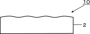
- FIG. 1 and 2 are cross-sectional views showing an embodiment of the antiglare film 10 of the present invention.
- the antiglare film 10 of FIG. 1 has an antiglare layer 2 on a transparent base material 1, and the antiglare film 10 of FIG. 2 has a single layer configuration of the antiglare layer 2.
- Condition 1 stipulates that P is 0.20 ⁇ m or more and 1.20 ⁇ m or less when the surface roughness of a 500 ⁇ m square region of the antiglare layer is measured and the maximum mountain height of the region is defined as P. ing.
- P is preferably 0.40 ⁇ m or more and 1.00 ⁇ m or less, more preferably 0.50 ⁇ m or more and 0.90 ⁇ m or less, and further preferably 0.60 ⁇ m or more and 0.80 ⁇ m or less.
- the maximum mountain height (P) of the condition 1 is the maximum height of the roughness curved surface of the target region (500 ⁇ m square region) when the average surface height of the target region (500 ⁇ m square region) is set to 0.
- the height of the average surface of the target region (area of 500 ⁇ m square) can be calculated by the following procedures (A1) to (A3). In the examples described later, (A1) and (A2) are executed at the same time by "Filter”, “Filter Low Wave” and “Filter Type” in the analysis items using the Microscope Application of MetroPro ver 8.3.2. To. (A1) A curved surface (waviness curved surface) obtained by removing high-frequency components from the measured curved surface is obtained.
- a roughness curved surface is obtained by subtracting the undulating curved surface from the measured curved surface.
- A3) Let the average height of the roughness curved surface be the average surface (height 0).
- the maximum height (P) of the roughness curved surface with the average surface as the reference (0) is a three-dimensional extension of the maximum peak height (Rp) of the roughness curve of JIS B0601: 2001, which is a two-dimensional parameter. It is similar to a thing.
- Condition 2 measures the surface roughness of a region of 500 ⁇ m square of the antiglare layer, and a surface having a height obtained by adding P / 6 to the average surface of the region is a first reference surface, and the first reference surface.
- N1 the number of convex portions exceeding the above
- N2 / N1 is 0.20 or more and 0.45 or less.
- FIG. 3 is a diagram for explaining how to count N1, N2, and N3 with respect to the condition 2 and the condition 3 described later.
- conditions 2 and 3 are three-dimensional parameters
- FIG. 3 shows two-dimensional data for simplification of explanation.
- the curve of FIG. 3 represents an XZ cross section of a predetermined portion in a region of 500 ⁇ m square.
- the curve of FIG. 3 is a cross-sectional curve of a predetermined portion in a region of 500 ⁇ m square.
- the solid straight line located at the bottom indicates the average plane (height 0) in the region of 500 ⁇ m square.
- the average height of the curves in FIG. 3 is correctly located above the solid line in FIG.
- FIG. 3A is two-dimensional, the condition 2 N1 is obtained by three-dimensionally counting the number of convex portions exceeding P / 6 within a region of 500 ⁇ m square. Further, the number of convex portions exceeding P / 3 is 5 in FIG. 3A.
- the condition 2 N2 is obtained by three-dimensionally counting the number of convex portions exceeding P / 3 within a region of 500 ⁇ m square. Further, the number of convex portions exceeding P / 2 is one in FIG. 3A. Although FIG. 3A is two-dimensional, the condition 3 N3 is obtained by three-dimensionally counting the number of convex portions exceeding P / 2 within a region of 500 ⁇ m square. Regarding conditions 2 and 3, the number of convex portions exceeding the first to third reference planes shall be counted as one convex portion at the stage of exceeding each reference plane and then falling below each reference plane. .. For example, in FIG.
- N2 / N1 is a convex portion (convex portion of height level 2) that exceeds the average height to some extent with respect to the number of convex portions (convex portion of height level 1) slightly exceeding the average height. Shows the ratio of the numbers. That is, the fact that N2 / N1 is 0.20 or more and 0.45 or less means that the number of convex portions at height level 2 is not too small and not too large with respect to the number of convex portions at height level 1. Means.
- N2 / N1 is a convex portion (convex portion of height level 2) that exceeds the average height to some extent with respect to the number of convex portions (convex portion of height level 1) slightly exceeding the average height. Shows the ratio of the numbers. That is, the fact that N2 / N1 is 0.20 or more and 0.45 or less means that the number of convex portions at height level 2 is not too small and not too large with respect to the number of convex portions at height level 1. Means.
- glare is caused by the surface unevenness of the antiglare layer acting as a lens. More specifically, first, the image light that has passed through the surface unevenness (lens) is refracted and focused on the focal point. Then, when the distance to the focal point (focal length) becomes a predetermined condition, the glare becomes noticeable.
- the surface unevenness can be regarded as a lens, and the height of the convex portion can be regarded as the steepness of the mountain. Therefore, if the incident angle distribution of the image light with respect to the surface unevenness is the same, the distance to the focal point (focal length) depends on the height of the convex portion.
- the incident angle distribution of the image light with respect to the surface unevenness is the same, glare can be suppressed by setting the convex portion at a constant height and setting the focal length within a constant range.
- the incident angle distribution of the image light with respect to the surface unevenness also differs. Therefore, when the convex portion has a constant height, even if the glare can be suppressed under a specific condition, the glare worsens if the gap between the display element and the antiglare layer is different.
- N2 / N1 indicates that the number of convex portions at height level 2 is equal to or more than a predetermined number with respect to the number of convex portions at height level 1.
- N2 / N1 is 0.20 or more, it means that convex portions having different focal lengths are mixed at a certain ratio. In this way, by mixing convex portions with different focal lengths, it is possible to prevent the glare from becoming extremely worse under specific conditions, and for various display devices with different distances between the display element and the antiglare layer. Glitter can be suppressed.
- N2 / N1 when N2 / N1 is more than 0.45, the number of convex portions does not change so much depending on the height level, and the convex portions have a constant height. That is, the fact that N2 / N1 is 0.45 or less under the condition 2 also means that convex portions having different focal lengths are mixed, and various display devices having different distances between the display element and the antiglare layer can be used. On the other hand, glare can be suppressed.
- N2 / N1 is preferably 0.22 or more and 0.40 or less, and more preferably 0.23 or more and 0.36 or less.
- the antiglare film may have at least a part of a 500 ⁇ m square region that satisfies conditions 1 and 2, but condition 1 and condition 2 may be satisfied at 7 or more of the 9 measurement points shown below. It is more preferable that the conditions 1 and 2 are satisfied at 8 or more locations, and it is further preferable that the conditions 1 and 2 are satisfied at all 9 locations. The same applies to other parameters related to the surface shape such as condition 3 described later.
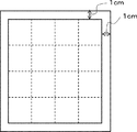
- the measurement points of 9 the area of 1 cm from the outer edge of the measurement sample is set as a margin, and 9 points of intersections are measured when a line is drawn to divide the vertical direction and the horizontal direction into four equal parts with respect to the area inside the margin. It is preferable to make it the center of.
- the measurement sample is a quadrangle
- the area 1 cm from the outer edge of the quadrangle is set as a margin, and the area inside the margin is divided into four equal parts in the vertical and horizontal directions. It is preferable to measure the surface roughness of a region of 500 ⁇ m square centered on the portion.
- the measurement sample has a shape other than a quadrangle such as a circle, an ellipse, a triangle, or a pentagon, it is preferable to draw a quadrangle inscribed in these shapes and measure the quadrangle at nine points by the above method.
- the antiglare film is in the form of a roll, it is preferable to cut out the roll-shaped antiglare film into a sheet and use the cut out sample to perform measurement at 9 points by the above method.
- the surface roughness of the 500 ⁇ m square region of the antiglare layer is measured using a white interference microscope with a cutoff value of ⁇ c (corresponding to “Filter Low Wavelen” in the example) of 250 ⁇ m. ..
- the variation of various parameters such as the surface shape and optical characteristics measured at the above nine points is preferably an average value of ⁇ 10%, more preferably an average value of ⁇ 8%, and an average value of ⁇ 6%. Is more preferable.
- the measured values of parameters such as the surface shape and optical characteristics of the antiglare film may not have a normal distribution, but at least within the range of the above variation, the effect based on each parameter is not hindered.
- the reason why the measured values of the parameters of the antiglare film may not have a normal distribution is considered as follows. When the antiglare layer coating liquid is applied to the transparent substrate, the abundance ratio of insoluble components such as particles contained in the antiglare layer coating liquid is not constant depending on the in-plane position of the antiglare film.
- the composition in the coating film is slightly different depending on the position in the plane. Furthermore, since the drying air cannot have a complete laminar flow, the drying conditions differ depending on the position in the plane. Moreover, the drying rate of the coating film does not change linearly but changes non-linearly due to these factors. Due to such a cause, it is considered that the measured values of the haze and the surface shape of the antiglare film may not have a normal distribution.
- a surface having a height obtained by adding P / 2 to the average height of a 500 ⁇ m square region satisfying the conditions 1 and 2 is used as a third reference surface.
- N3 the number of convex portions exceeding the third reference plane
- condition 3 the fact that N3 / N2 is 0.20 or more means that the number of convex parts (convex parts at height level 2) greatly exceeds the average height, while the number of convex parts greatly exceeds the average height. It shows that the number of (convex portions of height level 3) is equal to or more than a predetermined number. Therefore, if condition 3 is satisfied when N3 / N2 is 0.20 or more, surface irregularities having different focal lengths are further mixed, and for various display devices having different distances between the display element and the antiglare layer. Glitter can be further suppressed. Further, if N3 / N2 is too large, the number of convex portions does not change so much depending on the height level, and the convex portions have a constant height.
- N3 / N2 is 0.45 or less under the condition 3 also means that convex portions having different focal lengths are mixed, and various display devices having different distances between the display element and the antiglare layer can be used. On the other hand, glare can be suppressed.
- N3 / N2 is more preferably 0.22 or more and 0.40 or less, and further preferably 0.23 or more and 0.36 or less.
- N1 (the number of convex portions exceeding the first reference plane in a region of 500 ⁇ m square) is preferably 100 to 1000, preferably 150 to 800. Is more preferable, and 250 to 700 pieces are further preferable.
- N2 (the number of convex portions exceeding the second reference plane in a region of 500 ⁇ m square) is preferably 30 to 500, preferably 50 to 400. Is more preferable, and 70 to 250 pieces are further preferable.
- N3 (the number of convex portions exceeding the third reference plane in a region of 500 ⁇ m square) is preferably 10 to 100, preferably 15 to 80. Is more preferable, and 20 to 60 pieces are further preferable.
- the maximum height roughness PV of a 500 ⁇ m square region satisfying the above conditions 1 and 2 is preferably more than 0.60 ⁇ m and 1.50 ⁇ m or less, preferably 0.65 ⁇ m or more. It is more preferably 1.20 ⁇ m or less, and further preferably 0.70 ⁇ m or more and 1.00 ⁇ m or less.
- the PV By setting the PV to more than 0.60 ⁇ m, the antiglare property can be further improved. Further, by setting the PV to 1.50 ⁇ m or less, it is possible to easily suppress a decrease in visibility due to a foreign body sensation.
- the maximum height roughness (PV) is similar to a three-dimensional extension of the maximum height roughness (Rz) of the roughness curve of JIS B0601: 2001, which is a two-dimensional parameter.
- the arithmetic average roughness Sa of a 500 ⁇ m square region satisfying the above conditions 1 and 2 is preferably 0.020 ⁇ m or more and 0.070 ⁇ m or less, and 0.025 ⁇ m or more and 0. It is more preferably 0.065 ⁇ m or less, and further preferably 0.030 ⁇ m or more and 0.060 ⁇ m or less.
- Sa is more preferably 0.065 ⁇ m or less, and further preferably 0.030 ⁇ m or more and 0.060 ⁇ m or less.
- Sa is similar to the arithmetic mean roughness (Ra) of the roughness curve of JIS B0601: 2001, which is a two-dimensional parameter, extended to three dimensions.
- Ra arithmetic mean roughness
- the ten-point average roughness Sz of a 500 ⁇ m square region satisfying the above conditions 1 and 2 is preferably 0.20 ⁇ m or more and 1.20 ⁇ m or less, preferably 0.35 ⁇ m or more. It is more preferably 1.00 ⁇ m or less, and further preferably 0.50 ⁇ m or more and 0.80 ⁇ m or less.
- Sz 0.20 ⁇ m or more
- the antiglare property can be easily improved, the surface unevenness can be suppressed from becoming excessively uniform, and scratches and defects in the antiglare layer can be made inconspicuous. Further, by setting Sz to 1.20 ⁇ m or less, it is possible to easily suppress the decrease in contrast.
- the ten-point average roughness (Sz) of the present specification is defined as a mountain where the roughness surface is higher than the average surface and a valley where the area is lower than the average surface for each region protruding from the average surface.
- Sz The ten-point average roughness
- the maximum value of the sum is the summit and the minimum value of the valley height is the valley bottom
- the heights of the 5th peak from the highest peak are P1, P2, P3, P4, P5, respectively, and 5 from the lowest valley bottom.
- the heights of the valley bottoms up to the third are V1, V2, V3, V4, V5, respectively, they are expressed by the following formulas (P1 to P5 are positive and V1 to V5 are positive because they are based on the average plane). It is negative.).
- Sz ⁇ (P1 + P2 + P3 + P4 + P5)-(V1 + V2 + V3 + V4 + V5) ⁇ / 5 Note that Sz is similar to a three-dimensional extension of the ten-point average roughness (Rzjis) of JIS B0601: 2001, which is a two-dimensional parameter.
- Sz / Sa is preferably 10.0 or more and 22.0 or less in a 500 ⁇ m square region satisfying the above conditions 1 and 2, and 12.0 or more 20. It is more preferably 0 or less, and further preferably 13.0 or more and 18.0 or less.
- Sz / Sa is preferably 10.0 or more and 22.0 or less in a 500 ⁇ m square region satisfying the above conditions 1 and 2, and 12.0 or more 20. It is more preferably 0 or less, and further preferably 13.0 or more and 18.0 or less.
- the internal haze is preferably 6.0% or less, more preferably 4.5% or less, still more preferably 3.0% or less. It is even more preferably 1.5% or less.
- the internal haze is preferably 6.0% or less, more preferably 4.5% or less, still more preferably 3.0% or less. It is even more preferably 1.5% or less.
- optical characteristics such as internal haze shall mean the average of the measured values at the above-mentioned nine points.
- Internal haze and surface haze can be determined, for example, by the methods described in the Examples.
- the surface haze is preferably 1.0 to 15.0%, more preferably 2.0 to 10.0%, and 3.0 to 8. It is more preferably 0%.
- the surface haze is preferably 1.0 to 15.0%, more preferably 2.0 to 10.0%, and 3.0 to 8. It is more preferably 0%.
- the total light transmittance of JIS K7361-1: 1997 is preferably 80% or more, more preferably 85% or more, and more preferably 90% or more. More preferred.
- One embodiment of the antiglare film of the present invention is a transmission image according to JIS K7374: 2007 for each of the widths of the optical comb of 0.125 mm, 0.25 mm, 0.5 mm, 1.0 mm and 2.0 mm.
- the sharpness is measured, and the transmission image sharpness with a width of 0.125 mm is C 0.125 , the transmission image sharpness with a width of 0.25 mm is C 0.25 , and the transmission with a width of 0.5 mm is 0.5 mm.
- the transmitted image sharpness with an optical comb width of 1.0 mm is defined as C 1.0
- the transmitted image sharpness with an optical comb width of 2.0 mm is defined as C 2.0 , C 0.125 , C.
- the total of 0.25 , C 0.5 , C 1.0 and C 2.0 is preferably 380% or more. By setting the total of C 0.125 , C 0.25 , C 0.5 , C 1.0 and C 2.0 to 380% or more, it is possible to easily suppress the decrease in resolution.
- the total of C 0.125 , C 0.25 , C 0.5 , C 1.0 and C 2.0 is more preferably 400% or more, and further preferably 450% or more.
- the upper limit of the total of C 0.125 , C 0.25 , C 0.5 , C 1.0 and C 2.0 is about 490%.
- the difference between C 2.0 and C 0.125 is preferably 10.0% or less, more preferably 7.5% or less, and 5.0% or less. It is more preferably present, and even more preferably 3.0% or less. It can be said that the difference between C 2.0 and C 0.125 is 10.0% or less, which means that there are few wide convex portions that tend to worsen glare. Therefore, by setting the difference between C 2.0 and C 0.125 to 10.0% or less, glare can be more easily suppressed. Further, when the difference between C 2.0 and C 0.125 is 10.0% or less, it can be said that the ratio of the light diffused at a high angle to the light transmitted through the antiglare film is small.
- C 0.125 , C 0.25 , C 0.5 , C 1.0 and C 2.0 are each preferably 80% or more, more preferably 85% or more, and even more preferably 90% or more.
- C 0.125 , C 0.25 , C 0.5 , C 1.0 and C 2.0 are 80% or more, glare can be easily suppressed.
- the antiglazing film may be a single layer of an antiglazing layer, or may be a plurality of layers having an antiglazing layer on a transparent base material. From the viewpoint of handleability and ease of manufacture, a configuration having an antiglare layer on a transparent base material is preferable. Further, the antiglare film may have a functional layer such as an antireflection layer, an antifouling layer, and an antistatic layer.
- the surface of the antiglare film opposite to the side satisfying the conditions 1 and 2 is substantially smooth.
- the surface opposite to the uneven surface is substantially smooth.
- the surface of the transparent base material opposite to the surface having the antiglare layer is substantially smooth.
- the surface of the functional layer is substantially smooth.
- substantially smooth means that the Sa is less than 0.020 ⁇ m.
- the uneven shape of the surface of the antiglare layer can be formed by, for example, (A) a method using an embossed roll, (B) an etching treatment, (C) molding, (D) a coating film formed by a coating, or the like.
- A) a method using an embossed roll, (B) an etching treatment, (C) molding, (D) a coating film formed by a coating, or the like molding by the mold (C) is preferable from the viewpoint of reproducibility of the uneven shape, and formation of a coating film by the coating of (D) is preferable from the viewpoint of productivity and compatibility with various types. is there.
- a mold having a shape complementary to the uneven shape on the surface of the antiglare layer is prepared, and a material constituting the antiglare layer such as polymer resin or glass is poured into the mold and cured, and then the mold is formed. It can be manufactured by taking it out from.
- a transparent base material is used, it is manufactured by pouring a polymer resin or the like into a mold, superimposing the transparent base material on the mold, curing the polymer resin or the like, and removing the transparent base material from the mold. be able to.
- particles or additives are contained in the antiglare layer, particles or additives may be further poured when the polymer resin or the like is poured into the mold.
- an antiglare layer coating liquid containing a binder resin component, particles and a solvent onto a transparent substrate by a known coating method such as gravure coating or bar coating, and then dry the coating film. It can be formed by curing according to the above.
- a known coating method such as gravure coating or bar coating
- suitable materials described later it is preferable to use suitable materials described later as the binder resin component, particles and solvent.
- the particles preferably include particles having an average particle diameter of 0.5 to 5.0 ⁇ m and inorganic particles having an average particle diameter of 1 to 50 nm.
- particles having an average particle diameter of 0.5 to 5.0 ⁇ m may be referred to as “large particles”
- inorganic particles having an average particle diameter of 1 to 50 nm may be referred to as “inorganic fine particles”.
- the particles (large particles) having an average particle diameter of 0.5 to 5.0 ⁇ m either organic particles or inorganic particles can be used. By setting the average particle size of the large particles in the above range, the condition 1 can be easily satisfied.
- the average particle size of the large particles is preferably 1.0 to 4.0 ⁇ m, more preferably 1.5 to 3.0 ⁇ m.
- the heights of the convex portions are likely to be uniform, so that it is difficult to set N2 / N1 to 0.20 or more and 0.45 or less.
- the convex portion may become too large and the maximum mountain height P may exceed 1.20 ⁇ m. Therefore, it is preferable to appropriately control the dispersion of the large particles so that the dispersed large particles and the aggregated large particles are present in a well-balanced manner in the antiglare layer.
- the large particles may be a mixture of two or more kinds of particles having an average particle diameter, but from the viewpoint of facilitating dispersion control and easily satisfying the conditions 2 and 3, one having an average particle diameter of one kind may be used. preferable.
- the average particle size of large particles can be calculated by the following operations (i) to (iii).
- (I) Take a transmission observation image of the antiglare film with an optical microscope. The magnification is preferably 500 to 2000 times.
- Arbitrary 10 large particles are extracted from the observation image, and the particle size of each large particle is calculated. The particle diameter is measured as the distance between two straight lines in a combination of the two straight lines so that the distance between the two straight lines is maximized when the cross section of the large particle is sandwiched between two arbitrary parallel straight lines.
- the same operation is performed 5 times on the observation image on another screen of the same sample, and the value obtained from the number average of the particle diameters for a total of 50 particles is taken as the average particle diameter of the large particles.
- a section from (iv) antiglare film according to (iv) to (vi) below is prepared by a microtome so as to have a cross section passing through the center of the large particles.
- the thickness of the section is preferably 70 nm to 100 nm.
- a plurality of sections are continuously prepared for one large particle, and the section having the maximum particle diameter calculated from each section by the operation (v) is passed through the center. It can be a section to be a cross section.
- the obtained section is observed with a scanning electron microscope (STEM) to calculate the particle size.
- the method for calculating the particle size is the same as in (ii).
- the magnification is preferably 5000 to 20000 times.
- This operation is performed on 20 particles, and the value obtained from the number average of the particle diameters of 20 particles is taken as the average particle diameter of the large particles.
- large particles examples include spherical, disk-shaped, rugby ball-shaped, amorphous, and other shapes, and hollow particles, porous particles, solid particles, and the like having these shapes.
- spherical solid particles are preferable from the viewpoint of suppressing glare.
- Examples of the organic particles include particles composed of polymethylmethacrylate, polyacrylic-styrene copolymer, melamine resin, polycarbonate, polystyrene, polyvinyl chloride, benzoguanamine-melamine-formaldehyde condensate, silicone, fluororesin, polyester resin and the like. Can be mentioned.
- Examples of the inorganic particles include particles made of silica, alumina, zirconia, titania and the like. Among the above-mentioned large particles, organic particles that can facilitate dispersion control and easily satisfy conditions 2 and 3 are preferable. Further, the organic particles have a light specific gravity, and when used in combination with the inorganic fine particles, the organic particles are likely to emerge near the surface of the antiglare layer, which is preferable in that the antiglare property can be easily exhibited.
- polyacrylic-styrene copolymer particles are preferable.
- the polyacrylic-styrene copolymer particles are good in that the internal haze and the dispersion can be easily controlled because the degree of refractive index and the degree of polyhydrophobicity can be easily controlled.
- polyacrylic-styrene copolymer particles are used as the large particles, increasing the proportion of styrene to increase the degree of hydrophobicity improves the dispersibility, and conversely decreasing the proportion of styrene facilitates aggregation.
- the ratio of acrylic and styrene constituting the polyacrylic-styrene copolymer particles can be determined based on the refractive index of the particles. Specifically, since styrene has a higher refractive index than acrylic, it can be said that the higher the refractive index of the polyacrylic-styrene copolymer particles, the higher the proportion of styrene.
- the content of the large particles is preferably 1 to 25% by mass, preferably 2 to 10% by mass, based on the total solid content forming the antiglare layer, from the viewpoint of facilitating the conditions 1 and 2 and the like. More preferred.
- inorganic particles having an average particle diameter of 1 to 50 nm include fine particles made of silica, alumina, zirconia, titania and the like. Among these, silica, which easily suppresses the occurrence of internal haze, is preferable.
- the average particle size of the inorganic fine particles is preferably 10 to 40 nm, more preferably 20 to 30 nm.
- the average particle size of the inorganic fine particles can be calculated by the following operations (i) to (iii).
- (I) The cross section of the antiglare film is imaged by TEM or STEM.
- the TEM or STEM acceleration voltage is preferably 10 kv to 30 kV, and the magnification is preferably 50,000 to 300,000 times.
- the product name "S-4800 (TYPE2)" manufactured by Hitachi High-Technologies Corporation can be used for observation in the STEM observation mode. After cutting the sample to a size that can be placed on the sample table, it is pasted with silver paste or carbon paste, and Pt-Pd is sputtered for about 20 seconds to improve continuity.
- the acceleration voltage and emission current are 10 ⁇ A, and the focus is adjusted with a detector: TE, and the contrast and brightness are appropriately adjusted at a magnification of 50,000 to 300,000 while observing whether the contours of each particle can be distinguished.
- the aperture was set to 3 for the beam monitor and 3 for the objective lens. D. May be 8 mm.
- a dyeing treatment such as osmium tetroxide, ruthenium tetroxide, or phosphotungstic acid may be performed as a pretreatment.
- Arbitrary 10 inorganic fine particles are extracted from the observation image, and the particle size of each inorganic fine particle is calculated.
- the particle size is measured as the distance between two straight lines in a combination of the two straight lines so that the distance between the two straight lines is maximized when the cross section of the inorganic fine particles is sandwiched between two arbitrary parallel straight lines.
- the same operation is performed 5 times on the observation image on another screen of the same sample, and the value obtained from the number average of the particle diameters for a total of 50 particles is taken as the average particle diameter of the inorganic fine particles.
- the inorganic fine particles have a strong degree of hydrophilicity and the large particles have a strong degree of hydrophobicity. Therefore, by including the inorganic fine particles in the antiglare layer coating liquid, the large particles are easily dispersed in the coating liquid. However, when the large particles are excessively dispersed in the coating liquid, it becomes difficult to satisfy the conditions 2 and 3. Therefore, it is preferable to add a large amount of inorganic fine particles to increase the viscosity of the antiglare layer coating liquid so that the large particles are not excessively dispersed.
- the content of the inorganic fine particles is preferably 20 to 90% by mass, more preferably 30 to 80% by mass, and preferably 40 to 60% by mass in the total solid content forming the antiglare layer. More preferred. Within this range, large particles can be easily dispersed, polymerization shrinkage of the binder resin can be suppressed, and conditions 2 and 3 can be easily satisfied.
- the ratio of the contents of large particles and inorganic fine particles in the antiglare layer is 0.03 to 0.3. It is preferably 0.05 to 0.2, and more preferably 0.05 to 0.2.
- the inorganic fine particles are preferably reactive inorganic fine particles into which a reactive group has been introduced by surface treatment.
- a reactive group By introducing a reactive group, a large amount of inorganic fine particles can be contained in the antiglare layer, and conditions 2 and 3 can be easily satisfied.
- a polymerizable unsaturated group is preferably used, preferably a photocurable unsaturated group, and particularly preferably an ionizing radiation curable unsaturated group.
- a photocurable unsaturated group and particularly preferably an ionizing radiation curable unsaturated group.
- Specific examples thereof include ethylenically unsaturated bonds such as (meth) acryloyl group, (meth) acryloyloxy group, vinyl group and allyl group, and epoxy group.
- reactive inorganic fine particles include inorganic fine particles surface-treated with a silane coupling agent.
- the antiglare layer preferably has a region having a high density of inorganic fine particles in the vicinity of the surface.
- the region is preferably 5 to 200 nm in the thickness direction from the surface of the antiglare layer, and more preferably 20 to 100 nm.
- the binder resin of the antiglare layer preferably contains a cured product of the thermosetting resin composition or a cured product of the ionizing radiation curable resin composition, and from the viewpoint of improving the mechanical strength, the ionizing radiation curable resin composition. It is more preferable to include a cured product of the product. Further, from the viewpoint of adjusting the viscosity of the antiglare layer coating liquid to facilitate control of dispersion and aggregation of large particles, it is preferable to include a thermoplastic resin in addition to the ionizing radiation curable resin composition. The thermoplastic resin tends to increase the viscosity of the antiglare layer coating liquid as compared with the ionizing radiation curable resin composition.
- the thermosetting resin composition is a composition containing at least a thermosetting resin, and is a resin composition that is cured by heating.
- the thermosetting resin include acrylic resin, urethane resin, phenol resin, urea melamine resin, epoxy resin, unsaturated polyester resin, and silicone resin.
- a curing agent is added to these curable resins as needed.
- the ionizing radiation curable resin composition is a composition containing a compound having an ionizing radiation curable functional group (hereinafter, also referred to as “ionizing radiation curable compound”).
- ionizing radiation curable compound examples include an ethylenically unsaturated group such as a (meth) acryloyl group, a vinyl group and an allyl group, an epoxy group and an oxetanyl group.
- ionizing radiation curable compound a compound having an ethylenically unsaturated bond group is preferable, a compound having two or more ethylenically unsaturated bond groups is more preferable, and a compound having two or more ethylenically unsaturated bond groups is particularly preferable.
- Polyfunctional (meth) acrylate compounds are more preferred.
- the polyfunctional (meth) acrylate compound either a monomer or an oligomer can be used.
- ionizing radiation means electromagnetic waves or charged particle beams that have energy quanta capable of polymerizing or cross-linking molecules, and usually ultraviolet rays (UV) or electron beams (EB) are used. Electromagnetic waves such as X-rays and ⁇ -rays, and charged particle beams such as ⁇ -rays and ion rays can also be used.
- the bifunctional (meth) acrylate-based monomers include ethylene glycol di (meth) acrylate, bisphenol A tetraethoxydiacrylate, bisphenol A tetrapropoxydiacrylate, and 1,6-hexane. Examples thereof include diol diacrylate.
- the trifunctional or higher functional (meth) acrylate-based monomer include trimethylolpropane tri (meth) acrylate, pentaerythritol tri (meth) acrylate, pentaerythritol tetra (meth) acrylate, dipentaerythritol hexa (meth) acrylate, and di.
- Examples thereof include pentaerythritol tetra (meth) acrylate and isocyanuric acid-modified tri (meth) acrylate.
- the (meth) acrylate-based monomer is obtained by modifying a part of the molecular skeleton with ethylene oxide, propylene oxide, caprolactone, isocyanuric acid, alkyl, cyclic alkyl, aromatic, bisphenol or the like (modified (meth) acrylate). System monomer) may be used.
- the modified (meth) acrylate-based monomer is preferable because it can easily suppress shrinkage unevenness due to crosslinking. By suppressing the uneven shrinkage of the antiglare layer in this way, it is possible to suppress the non-uniform residual strain in the plane, and when the functional layer is formed on the antiglare layer, the functional layer It is possible to easily suppress peeling.
- the modified (meth) acrylate-based monomer is preferably modified with an alkylene oxide such as ethylene oxide or propylene oxide from the viewpoint of increasing the affinity with the inorganic fine particles and facilitating the suppression of aggregation of the inorganic fine particles.
- alkylene oxide-modified (meth) acrylate-based monomer include bisphenol F alkylene oxide-modified di (meth) acrylate, bisphenol A alkylene oxide-modified di (meth) acrylate, isocyanuric acid alkylene oxide-modified di (meth) acrylate, and polyalkylene. Examples thereof include glycol di (meth) acrylate, trimethylolpropane alkylene oxide-modified tri (meth) acrylate, and isocyanuric acid alkylene oxide-modified tri (meth) acrylate.
- the content of the modified (meth) acrylate-based monomer is preferably 10 to 80% by mass, more preferably 20 to 70% by mass, and 30 to 50% by mass with respect to the total amount of the ionizing radiation curable compound. Is more preferable.
- polyfunctional (meth) acrylate-based oligomer examples include acrylate-based polymers such as urethane (meth) acrylate, epoxy (meth) acrylate, polyester (meth) acrylate, and polyether (meth) acrylate.
- Urethane (meth) acrylate is obtained, for example, by reacting a polyhydric alcohol or an organic diisocyanate with a hydroxy (meth) acrylate.
- the preferable epoxy (meth) acrylate is a (meth) acrylate obtained by reacting a (meth) acrylic acid with a trifunctional or higher functional aromatic epoxy resin, an alicyclic epoxy resin, an aliphatic epoxy resin or the like, and a bifunctional epoxy resin.
- (Meta) acrylate obtained by reacting the above aromatic epoxy resin, alicyclic epoxy resin, aliphatic epoxy resin, etc. with polybasic acid and (meth) acrylic acid, and bifunctional or higher functional aromatic epoxy resin, It is a (meth) acrylate obtained by reacting an alicyclic epoxy resin, an aliphatic epoxy resin or the like with phenols and (meth) acrylic acid.
- the ionizing radiation curable compound may be used alone or in combination of two or more.
- the ionizing radiation curable compound when the ionizing radiation curable compound is an ultraviolet curable compound, the ionizing radiation curable composition preferably contains an additive such as a photopolymerization initiator or a photopolymerization accelerator.
- a photopolymerization initiator include one or more selected from acetophenone, benzophenone, ⁇ -hydroxyalkylphenone, Michler ketone, benzoin, benzyl dimethyl ketal, benzoyl benzoate, ⁇ -acyl oxime ester, thioxanthones and the like.
- the photopolymerization accelerator can reduce the polymerization inhibition by air at the time of curing and accelerate the curing rate, and is selected from, for example, p-dimethylaminobenzoic acid isoamyl ester, p-dimethylaminobenzoic acid ethyl ester and the like. One or more types can be mentioned.
- thermoplastic resin acrylic resin, cellulose resin, urethane resin, vinyl chloride resin, polyester resin, polyolefin resin, polycarbonate, nylon, polystyrene, ABS resin and the like can be used.
- acrylic resin is preferable, and among the acrylic resins, polymethylmethacrylate (PMMA) is preferable.
- the thermoplastic resin preferably has a polystyrene-equivalent weight average molecular weight of 20,000 to 200,000 measured by the GPC method, which is 50,000 to 100,000. Is more preferable.
- the content ratio of the thermoplastic resin in the total amount of the binder resin in the antiglare layer is preferably 10 to 30% by mass, more preferably 15 to 25% by mass.
- the thickness of the antiglare layer is preferably 1 to 10 ⁇ m, more preferably 2 to 7 ⁇ m, from the viewpoint of curl suppression, mechanical strength, hardness and toughness.
- the variation in the thickness of the antiglare layer is preferably within ⁇ 15%, more preferably within ⁇ 10%, further preferably within ⁇ 7%, and within 5% with respect to the average film thickness. Is even more preferable.
- the thickness of the antiglare layer can be calculated by selecting 20 arbitrary points in the cross-sectional photograph of the antiglare film by a scanning transmission electron microscope (STEM) and averaging them.
- the ratio of the thickness of the antiglare layer to the average particle size of the large particles is 0.50 to 0 from the viewpoint of facilitating the satisfaction of conditions 1 to 3 and the like. It is preferably .85, and more preferably 0.55 to 0.80.
- a solvent is usually used to adjust the viscosity and to make each component soluble or dispersible. Since the surface shape of the antiglare layer after coating and drying differs depending on the type of solvent, it is preferable to select the solvent in consideration of the saturated vapor pressure of the solvent, the permeability of the solvent into the transparent substrate, and the like.
- the solvent is, for example, ketones (acetone, methyl ethyl ketone, methyl isobutyl ketone, cyclohexanone, etc.), ethers (dioxane, tetrahydrofuran, etc.), aliphatic hydrocarbons (hexane, etc.), alicyclic hydrocarbons.
- ketones acetone, methyl ethyl ketone, methyl isobutyl ketone, cyclohexanone, etc.
- ethers dioxane, tetrahydrofuran, etc.
- aliphatic hydrocarbons hexane, etc.
- alicyclic hydrocarbons alicyclic hydrocarbons.
- Cyclohexane, etc. aromatic hydrocarbons (toluene, xylene, etc.), carbon halides (di dichloromethane, dichloroethane, etc.), esters (methyl acetate, ethyl acetate, butyl acetate, etc.), alcohols (n-butyl alcohol, etc.) Cyclohexanol, etc.), glycol ethers (ethyl cellosolve, propylene glycol monomethyl ether, propylene glycol monomethyl ether acetate, etc.), sulfoxides (dimethyl sulfoxide, etc.), amides (dimethylformamide, dimethylacetamide, etc.), etc. can be exemplified. It may be a mixture.
- a solvent having a high drying rate is selected in order to prevent agglomeration of particles.
- the solvent also contains a solvent having a slow drying rate.
- a solvent having a slow drying rate is mixed with a solvent having a high drying rate, the dispersibility of the large particles changes rapidly, and the large particles may be excessively agglomerated. Therefore, it is preferable to use a glycol ether-based solvent as the solvent having a slow drying rate.
- Glycol ether-based solvents have a slow drying rate, which makes it easier for large particles to aggregate, while they are more hydrophilic than other solvents, so they are less likely to aggregate large particles (organic particles) than other solvents. That is, by using a glycol ether-based solvent as the solvent having a slow drying rate, the dispersibility does not change abruptly, so that large particles (organic particles) can be easily aggregated appropriately.
- the solvent having a high drying rate preferably has a relative evaporation rate (relative evaporation rate when the evaporation rate of n-butyl acetate is 100) of 100 or more.
- the solvent having a slow drying rate preferably has a relative evaporation rate of less than 100, more preferably 20 to 80, and even more preferably 30 to 60.
- the mass ratio of the solvent having a high relative evaporation rate to the solvent having a slow relative evaporation rate is preferably 30:70 to 95: 5, more preferably 40:60 to 90:10, and 50:50. It is more preferably ⁇ 85:15.
- Examples of relative evaporation rates are 195 for toluene, 465 for methyl ethyl ketone (MEK), 118 for methyl isobutyl ketone (MIBK), and 34 for propylene glycol monomethyl ether acetate.
- the drying conditions can be controlled by the drying temperature and the wind speed in the dryer.
- the specific drying temperature is preferably 30 to 120 ° C.
- the drying air speed is preferably 0.2 to 50 m / s.
- the antiglare layer coating liquid may contain a leveling agent.
- the leveling agent include a silicone-based leveling agent and a fluorine-based leveling agent.
- the amount of the leveling agent added is preferably 0.01 to 0.5% by weight, more preferably 0.05 to 0.2% by weight, based on the total solid content of the antiglare layer coating liquid.
- the transparent base material preferably has light transmission, smoothness, heat resistance, and excellent mechanical strength.
- a transparent substrate include polyester, triacetyl cellulose (TAC), cellulose diacetate, cellulose acetate butyrate, polyamide, polyimide, polyether sulphon, poly sulphon, polypropylene, polymethylpentene, polyvinyl chloride, and polyvinyl acetal.
- the plastic film may be a combination of two or more plastic films.
- stretch-processed polyester (polyethylene terephthalate, polyethylene naphthalate) is particularly preferable.
- TAC and acrylic are suitable from the viewpoint of light transmission and optical isotropic property.
- COP and polyester are suitable because they have excellent weather resistance.
- the plastic film having a retardation value of 3000 to 30,000 nm and the plastic film having a 1/4 wavelength phase difference can suppress the observation of uneven colors on the display screen when the image of the liquid crystal display is observed through polarized sunglasses. It is suitable in terms of points.
- the thickness of the transparent substrate is preferably 5 to 300 ⁇ m, more preferably 30 to 200 ⁇ m.
- the preferable upper limit of the thickness of the transparent base material is 60 ⁇ m, and the more preferable upper limit is 50 ⁇ m.
- the transparent base material is a low moisture permeable base material such as polyester, COP, or acrylic
- the preferable upper limit of the thickness of the transparent base material for thinning is 40 ⁇ m, and the more preferable upper limit is 20 ⁇ m. Even in the case of a large screen, if the upper limit of the thickness of the transparent base material is within the above-mentioned range, it is also preferable in that distortion can be made less likely to occur.
- the thickness of the transparent base material can be measured with a Digimatic standard outside micrometer (manufactured by Mitutoyo Co., Ltd., product number "MDC-25SX") or the like.
- the thickness of the transparent base material may be such that the average value measured at any 10 points is the above value, and the variation in thickness is preferably in the range of ⁇ 8% of the average value, and is in the range of ⁇ 4% of the average value.
- the average value is in the range of ⁇ 3% (if the average value of the thickness is 50 ⁇ m, each thickness is preferably within the range of 46 to 54 ⁇ m, and each thickness is It is preferably within the range of 48 to 52 ⁇ m, and more preferably each thickness is within the range of 48.5 to 51.5 ⁇ m).
- a paint called an anchor agent or a primer may be applied to the surface of the transparent base material in advance in order to improve the adhesiveness.
- the antiglare film may have a functional layer such as an antireflection layer, an antifouling layer, and an antistatic layer.
- the functional layer can be formed on, for example, an antiglare layer. Further, when the antiglare layer is provided on the transparent base material, the functional layer can be formed on the side opposite to the antiglare layer of the transparent base material.
- the antiglare film may be single-wafered or roll-shaped.
- the size of the single leaf is not particularly limited, but the maximum diameter is about 2 to 500 inches.
- the "maximum diameter" means the maximum length when any two points of the antiglare film are connected. For example, when the antiglare film is rectangular, the diagonal of the region is the maximum diameter. When the antiglare film is circular, the diameter is the maximum.
- the shape of the single leaf is also not particularly limited, and may be, for example, a polygon (triangle, quadrangle, pentagon, etc.), a circle, or a random amorphous shape.
- the width and length of the roll shape are not particularly limited, but generally, the width is 500 to 3000 mm and the length is about 100 to 5000 m.
- the roll-shaped antiglare film can be cut into a single-wafer shape according to the size of an image display device or the like. When cutting, it is preferable to exclude the end of the roll whose physical properties are not stable.
- the method for selecting an antiglare film having an antiglare layer of the present invention is as follows.
- the surface roughness of a 500 ⁇ m square region of the antiglare layer was measured, the maximum mountain height was P, and the surface consisting of the average height plus P / 6 was the first reference surface, the first reference.
- the number of convex portions exceeding the surface is defined as N1
- the surface consisting of the height obtained by adding P / 3 to the average height is defined as the second reference surface
- the number of convex portions exceeding the second reference surface is defined as N2.
- the determination condition is whether or not the region has a 500 ⁇ m square area that satisfies the following conditions 1 and 2, and the one that satisfies the determination condition is selected.
- ⁇ Condition 1> P is 0.20 ⁇ m or more and 1.20 ⁇ m or less
- conditions 1 and 2 as determination conditions are the same as those of the antiglare film of the present invention described above.
- the method for selecting the antiglare film of the present invention preferably includes the above-mentioned preferred embodiment of the antiglare film of the present invention as a determination condition.
- the antiglare article of the present invention is arranged on a member so that the surface of the antiglare film of the present invention described above on the antiglare layer side faces the surface side.
- the member is not particularly limited as long as it has transparency, and examples thereof include a plastic plate and a glass plate.
- the touch panel of the present invention is a touch panel having a transparent substrate on its surface, and is arranged as the transparent substrate so that the surface of the antiglare film of the present invention described above faces the surface side. is there.
- touch panel examples include general-purpose touch panels such as a resistive film type, a capacitance type, an electromagnetic induction type, an infrared type, and an ultrasonic type.
- the display device of the present invention is a display device having a display element and an antiglare film arranged on the light emitting surface side of the display element, and the antiglare film of the present invention described above as the antiglare film. It is arranged so that the surface on the glare layer side faces the side opposite to the display element.
- Examples of the display element include a liquid crystal display element, an EL display element (organic EL display element, an inorganic EL display element), a plasma display element, and the like, and further, an LED display element such as a micro LED display element.
- liquid crystal display element examples include a TN method, an STN method, a TSTN method, an IPS method, a VA method, a multi-domain method, and an OCB method. Further, an in-cell touch panel liquid crystal element having a touch panel function incorporated in any of these methods can also be mentioned.
- the distance (gap) between the display element and the antiglare layer of the antiglare film is not particularly limited, but the display device of the present invention can suppress glare regardless of the gap.
- the display device of the present invention can suppress glare even when the gap exceeds 0.7 mm. Further, as shown in Examples described later, glare can be suppressed even if the gap is 2.5 mm.
- a TAC film manufactured by Fujifilm, TD80UL
- a transparent adhesive manufactured by Panac, PD-S1, thickness 25 ⁇ m
- Sample B was prepared by crushing the uneven shape and flattening it to eliminate the influence of haze caused by the surface shape.
- the haze of sample B was measured to determine the internal haze (Hi).
- the measurement was performed at 9 points for each sample B.
- the internal haze was subtracted from the total haze to obtain the surface haze (Hs).
- the atmosphere at the time of measuring the haze and the total light transmittance was a temperature of 23 ° C.
- a Microscope Application of MetroPro ver9.0.10 was used for the measurement.
- Microscope Application and Advanced Texture Application of MetroPro ver8.3.2 were used.
- the other eight locations also satisfied the conditions 1 to 3.
- the atmosphere at the time of measurement was a temperature of 23 ° C. ⁇ 5 ° C. and a humidity of 50% ⁇ 10%. Further, before the start of measurement, each sample C was left in an atmosphere of 23 ° C. ⁇ 5 ° C. and a humidity of 50% ⁇ 10% for 10 minutes or more.
- Glitter (gap approx. 0.8 mm)
- the surface of the antiglare film on the transparent substrate 1 side and the surface on the side where the black matrix (glass thickness 0.7 mm, pixel density of the black matrix is equivalent to 350 ppi) 300 is not formed are formed of wrinkles, fingerprints, etc.
- a sample D1 for glaring evaluation was prepared by laminating through a transparent adhesive layer 200 (25 ⁇ m thickness, manufactured by Panac Co., Ltd., product number: PD-S1) so that dirt, dust, and air were not observed as much as possible.
- the gap between the display element and the antiglare layer is considered to be 0.805 mm (black matrix glass thickness 0.7 mm + transparent adhesive layer thickness 0.025 mm + transparent base material thickness 0.08 mm).
- Light is irradiated from the black matrix side of the evaluation sample D1 in a dark room with a white surface light source 500 (HIGHTHBOX manufactured by HAKUBA, average brightness 1000 cd / m 2 ) to generate pseudo glare, and the antiglare layer 2 side.
- a white surface light source 500 HIGHTHBOX manufactured by HAKUBA, average brightness 1000 cd / m 2
- a CCD camera 600 KP-M1, C mount adapter, close-up ring; PK-11A Nikon, camera lens; 50 mm, F1.4s NIKKOR.
- FIG. 5 is a schematic view when performing the above-mentioned measurement.
- Image taken with a CCD camera using image processing software (ImagePro Plus ver.6.2; manufactured by Media Cybernetics) through an image board (Pro-Series Computer Kit Specrim Pro For Windows 2000 & XP Pro Ver. 1) It was taken into a personal computer, and image data consisting of an aggregate of the brightness of each pixel was obtained.
- image processing software ImagePro Plus ver.6.2; manufactured by Media Cybernetics
- image board Provides Computer Kit Specrim Pro For Windows 2000 & XP Pro Ver. 1
- image data consisting of an aggregate of the brightness of each pixel was obtained.
- the analysis was performed using the same software as follows.
- the contrast enhancement was performed with the contrast enhancement command as "contrast: 96, brightness: 48".
- the obtained image data was converted into an 8-bit gray scale (256 gradations of gray scale).
- the obtained image data was converted into a luminance of 256 gradations having a maximum value of 255 and a minimum value of 0 (no unit because of the conversion value).
- the brightness of the light source was adjusted so that the average brightness in this region was 120 to 140.
- the glare value was calculated in the same manner as in 1-4 except that the glare evaluation sample D1 was changed to the following glare evaluation sample D2 or D3.
- the gap between the display element and the antiglare layer is 1.905 mm (black matrix glass thickness 0.7 mm + thickness 1.1 mm glass + transparent adhesive layer thickness 0.025 mm + transparent base material). It can be regarded as a thickness of 0.08 mm).
- the gap between the display element and the antiglare layer is 2.605 mm (black matrix glass thickness 0.7 mm + thickness 1.8 mm glass + transparent adhesive layer thickness 0.025 mm + transparent base material). It can be regarded as a thickness of 0.08 mm).
- the black matrix 300 and the glass are laminated by fixing the ends with tape in a state where both members are overlapped.
- a glass and a thickness of 1.1 mm are arranged between the black matrix 300 of the glaring evaluation sample D1 and the transparent adhesive layer 200.
- a glass having a thickness of 1.8 mm is arranged between the black matrix 300 of the glaring evaluation sample D1 and the transparent adhesive layer 200.
- Anti-glare A sample for anti-glare evaluation is made by attaching a black acrylic plate to the transparent base material side of the anti-glare film to prevent wrinkles, fingerprints, and other stains, dust, and air from being seen through a transparent adhesive. was produced. The sample was visually in a bright room environment (environment where the illuminance on the antiglare film was 800 to 1200 Lx), and 15 subjects did not notice the observer and the background reflection of the observer. Whether or not the sex was obtained was evaluated according to the following criteria. A: 10 or more people answered good B: 5-9 people answered good C: 4 or less people answered good
- Example 1 An antiglare layer coating solution 1 having the following formulation was applied onto a transparent substrate (thickness 80 ⁇ m triacetyl cellulose resin film (TAC), manufactured by FUJIFILM Corporation, TD80UL) and dried at 70 ° C. and a wind speed of 5 m / s for 30 seconds. Then, ultraviolet rays were irradiated under a nitrogen atmosphere (oxygen concentration of 200 ppm or less) so that the integrated light amount was 100 mJ / cm 2 , to form an antiglare layer, and an antiglare film of Example 1 was obtained. The film thickness of the antiglare layer was 3.0 ⁇ m. The Sa on the side opposite to the antiglare layer of the antiglare film was 0.012 ⁇ m.
- TAC triacetyl cellulose resin film
- Example 2 in the same manner as in Example 1 except that the antiglare layer coating solution 1 was changed to the antiglare layer coating solution 2 having the following formulation and the film was applied so that the film thickness of the antiglare layer was 5.0 ⁇ m. I got an anti-glare film.
- Example 3 An antiglare film of Example 3 was obtained in the same manner as in Example 1 except that the antiglare layer coating liquid 1 was changed to the antiglare layer coating liquid 3 of the following formulation.
- ⁇ Anti-glare layer coating liquid 3> ⁇ Pentaerythritol triacrylate 30 parts (manufactured by Nippon Kayaku Co., Ltd., KAYARAD-PET-30) -Isocyanuric acid EO-modified triacrylate 25 parts (manufactured by Toagosei Corporation, M-313) ⁇ 12 parts of acrylic polymer (manufactured by Mitsubishi Rayon, molecular weight 75,000) -Photopolymerization initiator 3 parts (IGM Resins BV, manufactured by Omnirad 184) -Silicone-based leveling agent 0.12 parts (manufactured by Momentive Performance Materials, TSF4460) ⁇ 5 parts of translucent particles (Sekisui Plastics Co., Ltd., spherical polyacrylic
- Comparative Example 1 An antiglare film of Comparative Example 1 was obtained in the same manner as in Example 2 except that the antiglare layer coating liquid 2 was changed to the antiglare layer coating liquid 4 having the following formulation.
- ⁇ Anti-glare layer coating liquid 4> ⁇ Pentaerythritol triacrylate 40 parts (manufactured by Nippon Kayaku Co., Ltd., KAYARAD-PET-30) ⁇ 60 parts of urethane acrylate (manufactured by DIC, V-4000BA) -Photopolymerization initiator 3 parts (IGM Resins BV, manufactured by Omnirad 184) -Silicone-based leveling agent 0.12 parts (manufactured by Momentive Performance Materials, TSF4460) ⁇ 11 parts of translucent particles (Sekisui Plastics Co., Ltd., spherical polystyrene polymer) (Average particle size 3.0 ⁇ m, refractive index 1.595) (The ratio of particles with a particle
- Comparative Example 2 An antiglare film of Comparative Example 2 was obtained in the same manner as in Example 2 except that the antiglare layer coating liquid 2 was changed to the antiglare layer coating liquid 5 having the following formulation.
- Comparative Example 3 An antiglare film of Comparative Example 3 was obtained in the same manner as in Example 2 except that the antiglare layer coating liquid 2 was changed to the antiglare layer coating liquid 6 having the following formulation.
- the antiglare film of the example has a low glare value of 14.0 or less at any gap, and the variation of the numerical value is also suppressed.
- the antiglare film of the comparative example the fluctuation of the glare value was large due to the change of the gap. That is, it can be confirmed that the antiglare film of the example has antiglare properties and can stably suppress glare regardless of the gap between the display element and the antiglare layer.
- Transparent base material 2 Anti-glare layer 10: Anti-glare film 200: Transparent adhesive layer 300: Black matrix 500: White surface light source 600: CCD camera 700: Support 800: Horizontal base
Landscapes
- Physics & Mathematics (AREA)
- General Physics & Mathematics (AREA)
- Engineering & Computer Science (AREA)
- Optics & Photonics (AREA)
- Nonlinear Science (AREA)
- Theoretical Computer Science (AREA)
- General Engineering & Computer Science (AREA)
- Chemical & Material Sciences (AREA)
- Crystallography & Structural Chemistry (AREA)
- Mathematical Physics (AREA)
- Human Computer Interaction (AREA)
- Optical Elements Other Than Lenses (AREA)
- Laminated Bodies (AREA)
- Liquid Crystal (AREA)
- Devices For Indicating Variable Information By Combining Individual Elements (AREA)
- Electroluminescent Light Sources (AREA)
Abstract
Priority Applications (5)
| Application Number | Priority Date | Filing Date | Title |
|---|---|---|---|
| US17/615,412 US12130408B2 (en) | 2019-06-07 | 2020-05-26 | Anti-glare film; anti-glare article, touchscreen, and display device using same; and method for selecting anti-glare film |
| KR1020227000059A KR102861524B1 (ko) | 2019-06-07 | 2020-05-26 | 방현 필름, 그리고 그것을 사용한 방현성 물품, 터치 패널 및 표시 장치, 그리고 방현 필름의 선정 방법 |
| CN202080041042.3A CN114008491B (zh) | 2019-06-07 | 2020-05-26 | 防眩膜及使用了该防眩膜的防眩性物品、触摸面板及显示装置、以及防眩膜的选定方法 |
| EP20818693.2A EP3982168B1 (fr) | 2019-06-07 | 2020-05-26 | Film antireflet ; article antireflet, écran tactile et dispositif d'affichage l'utilisant ; et procédé de sélection de film antireflet |
| JP2021524777A JP7464051B2 (ja) | 2019-06-07 | 2020-05-26 | 防眩フィルム、並びにそれを用いた防眩性物品、タッチパネル及び表示装置、並びに防眩フィルムの選定方法 |
Applications Claiming Priority (2)
| Application Number | Priority Date | Filing Date | Title |
|---|---|---|---|
| JP2019-107214 | 2019-06-07 | ||
| JP2019107214 | 2019-06-07 |
Publications (1)
| Publication Number | Publication Date |
|---|---|
| WO2020246314A1 true WO2020246314A1 (fr) | 2020-12-10 |
Family
ID=73651993
Family Applications (1)
| Application Number | Title | Priority Date | Filing Date |
|---|---|---|---|
| PCT/JP2020/020740 Ceased WO2020246314A1 (fr) | 2019-06-07 | 2020-05-26 | Film antireflet ; article antireflet, écran tactile et dispositif d'affichage l'utilisant ; et procédé de sélection de film antireflet |
Country Status (7)
| Country | Link |
|---|---|
| US (1) | US12130408B2 (fr) |
| EP (1) | EP3982168B1 (fr) |
| JP (1) | JP7464051B2 (fr) |
| KR (1) | KR102861524B1 (fr) |
| CN (1) | CN114008491B (fr) |
| TW (1) | TWI843855B (fr) |
| WO (1) | WO2020246314A1 (fr) |
Cited By (6)
| Publication number | Priority date | Publication date | Assignee | Title |
|---|---|---|---|---|
| WO2022264986A1 (fr) * | 2021-06-14 | 2022-12-22 | 大日本印刷株式会社 | Stratifié antireflet, stratifié optique, plaque polarisante et dispositif d'affichage d'image |
| JP2022190399A (ja) * | 2021-06-14 | 2022-12-26 | 大日本印刷株式会社 | 光学積層体、偏光板及び画像表示装置 |
| JP2022190398A (ja) * | 2021-06-14 | 2022-12-26 | 大日本印刷株式会社 | 防眩性積層体、偏光板及び画像表示装置 |
| JP2022190395A (ja) * | 2021-06-14 | 2022-12-26 | 大日本印刷株式会社 | 防眩性積層体、偏光板及び画像表示装置 |
| JP2023066397A (ja) * | 2021-10-28 | 2023-05-15 | 大日本印刷株式会社 | 防眩フィルム及び画像表示装置 |
| JP2023175912A (ja) * | 2022-03-29 | 2023-12-12 | リンテック株式会社 | 防眩フィルム及びその製造方法 |
Citations (7)
| Publication number | Priority date | Publication date | Assignee | Title |
|---|---|---|---|---|
| WO2013015039A1 (fr) * | 2011-07-26 | 2013-01-31 | 株式会社きもと | Panneau tactile du type à capacité électrostatique et film anti-éblouissement |
| JP2014048345A (ja) * | 2012-08-29 | 2014-03-17 | Dainippon Printing Co Ltd | 光学積層体、偏光板及び画像表示装置 |
| JP2016035574A (ja) | 2014-08-01 | 2016-03-17 | 日東電工株式会社 | 防眩フィルムおよび画像表示装置 |
| WO2016136871A1 (fr) * | 2015-02-26 | 2016-09-01 | 大日本印刷株式会社 | Panneau tactile, dispositif d'affichage, feuille optique, procédé de sélection de feuille optique et procédé de fabrication de feuille optique |
| JP2018189975A (ja) * | 2018-07-10 | 2018-11-29 | 大日本印刷株式会社 | 防眩フィルム、偏光板、液晶パネルおよび画像表示装置 |
| JP2019020728A (ja) * | 2017-07-14 | 2019-02-07 | 大日本印刷株式会社 | 防眩フィルム及び表示装置 |
| WO2019065865A1 (fr) * | 2017-09-29 | 2019-04-04 | 大日本印刷株式会社 | Film antireflet et dispositif d'affichage l'utilisant |
Family Cites Families (8)
| Publication number | Priority date | Publication date | Assignee | Title |
|---|---|---|---|---|
| JP4510124B2 (ja) * | 2008-03-31 | 2010-07-21 | 日東電工株式会社 | 画像表示装置用防眩性ハードコートフィルム、それを用いた偏光板および画像表示装置 |
| WO2010113827A1 (fr) | 2009-03-30 | 2010-10-07 | 日本製紙ケミカル株式会社 | Film de revêtement dur antireflet |
| JP2011081217A (ja) * | 2009-10-07 | 2011-04-21 | Nitto Denko Corp | 防眩性ハードコートフィルム、それを用いた偏光板および画像表示装置、ならびに防眩性ハードコートフィルムの製造方法 |
| JP5948763B2 (ja) * | 2011-08-29 | 2016-07-06 | 大日本印刷株式会社 | 防眩性フィルム、偏光板及び画像表示装置 |
| JP5653378B2 (ja) * | 2011-09-27 | 2015-01-14 | 日本製紙株式会社 | 防眩ハードコートフィルム |
| JP2014119552A (ja) * | 2012-12-14 | 2014-06-30 | Sumitomo Chemical Co Ltd | 防眩フィルムおよびそのための金型の製造方法、防眩フィルムの製造方法 |
| JP6168360B2 (ja) | 2014-09-01 | 2017-07-26 | 株式会社オートネットワーク技術研究所 | 回路構成体及び回路構成体の製造方法 |
| US10690818B2 (en) * | 2014-10-31 | 2020-06-23 | Corning Incorporated | Anti-glare substrates with a uniform textured surface and low sparkle and methods of making the same |
-
2020
- 2020-05-26 US US17/615,412 patent/US12130408B2/en active Active
- 2020-05-26 WO PCT/JP2020/020740 patent/WO2020246314A1/fr not_active Ceased
- 2020-05-26 JP JP2021524777A patent/JP7464051B2/ja active Active
- 2020-05-26 CN CN202080041042.3A patent/CN114008491B/zh active Active
- 2020-05-26 KR KR1020227000059A patent/KR102861524B1/ko active Active
- 2020-05-26 EP EP20818693.2A patent/EP3982168B1/fr active Active
- 2020-05-27 TW TW109117675A patent/TWI843855B/zh active
Patent Citations (7)
| Publication number | Priority date | Publication date | Assignee | Title |
|---|---|---|---|---|
| WO2013015039A1 (fr) * | 2011-07-26 | 2013-01-31 | 株式会社きもと | Panneau tactile du type à capacité électrostatique et film anti-éblouissement |
| JP2014048345A (ja) * | 2012-08-29 | 2014-03-17 | Dainippon Printing Co Ltd | 光学積層体、偏光板及び画像表示装置 |
| JP2016035574A (ja) | 2014-08-01 | 2016-03-17 | 日東電工株式会社 | 防眩フィルムおよび画像表示装置 |
| WO2016136871A1 (fr) * | 2015-02-26 | 2016-09-01 | 大日本印刷株式会社 | Panneau tactile, dispositif d'affichage, feuille optique, procédé de sélection de feuille optique et procédé de fabrication de feuille optique |
| JP2019020728A (ja) * | 2017-07-14 | 2019-02-07 | 大日本印刷株式会社 | 防眩フィルム及び表示装置 |
| WO2019065865A1 (fr) * | 2017-09-29 | 2019-04-04 | 大日本印刷株式会社 | Film antireflet et dispositif d'affichage l'utilisant |
| JP2018189975A (ja) * | 2018-07-10 | 2018-11-29 | 大日本印刷株式会社 | 防眩フィルム、偏光板、液晶パネルおよび画像表示装置 |
Non-Patent Citations (1)
| Title |
|---|
| See also references of EP3982168A4 |
Cited By (11)
| Publication number | Priority date | Publication date | Assignee | Title |
|---|---|---|---|---|
| WO2022264986A1 (fr) * | 2021-06-14 | 2022-12-22 | 大日本印刷株式会社 | Stratifié antireflet, stratifié optique, plaque polarisante et dispositif d'affichage d'image |
| JP2022190399A (ja) * | 2021-06-14 | 2022-12-26 | 大日本印刷株式会社 | 光学積層体、偏光板及び画像表示装置 |
| JP2022190398A (ja) * | 2021-06-14 | 2022-12-26 | 大日本印刷株式会社 | 防眩性積層体、偏光板及び画像表示装置 |
| JP2022190395A (ja) * | 2021-06-14 | 2022-12-26 | 大日本印刷株式会社 | 防眩性積層体、偏光板及び画像表示装置 |
| JP7793896B2 (ja) | 2021-06-14 | 2026-01-06 | 大日本印刷株式会社 | 光学積層体、偏光板及び画像表示装置 |
| JP7823324B2 (ja) | 2021-06-14 | 2026-03-04 | 大日本印刷株式会社 | 防眩性積層体、偏光板及び画像表示装置 |
| JP7834971B2 (ja) | 2021-06-14 | 2026-03-25 | 大日本印刷株式会社 | 防眩性積層体、偏光板、画像表示装置及び防眩性積層体の製造方法 |
| JP2023066397A (ja) * | 2021-10-28 | 2023-05-15 | 大日本印刷株式会社 | 防眩フィルム及び画像表示装置 |
| JP7347627B2 (ja) | 2021-10-28 | 2023-09-20 | 大日本印刷株式会社 | 防眩フィルム及び画像表示装置 |
| JP2023175912A (ja) * | 2022-03-29 | 2023-12-12 | リンテック株式会社 | 防眩フィルム及びその製造方法 |
| JP7506814B2 (ja) | 2022-03-29 | 2024-06-26 | リンテック株式会社 | 防眩フィルム及びその製造方法 |
Also Published As
| Publication number | Publication date |
|---|---|
| CN114008491B (zh) | 2024-09-03 |
| KR20220016952A (ko) | 2022-02-10 |
| EP3982168B1 (fr) | 2024-12-11 |
| CN114008491A (zh) | 2022-02-01 |
| US20220229208A1 (en) | 2022-07-21 |
| EP3982168A4 (fr) | 2023-08-09 |
| EP3982168A1 (fr) | 2022-04-13 |
| US12130408B2 (en) | 2024-10-29 |
| JPWO2020246314A1 (fr) | 2020-12-10 |
| KR102861524B1 (ko) | 2025-09-18 |
| TW202101087A (zh) | 2021-01-01 |
| JP7464051B2 (ja) | 2024-04-09 |
| TWI843855B (zh) | 2024-06-01 |
Similar Documents
| Publication | Publication Date | Title |
|---|---|---|
| JP7192777B2 (ja) | 防眩フィルム及びそれを用いた表示装置 | |
| JP7464051B2 (ja) | 防眩フィルム、並びにそれを用いた防眩性物品、タッチパネル及び表示装置、並びに防眩フィルムの選定方法 | |
| CN104915050B (zh) | 触摸面板、显示装置和光学片、以及光学片的筛选方法和光学片的制造方法 | |
| KR20180063259A (ko) | 광학 시트, 편광판, 광학 시트의 선별 방법 및 광학 시트의 제조 방법, 그리고 표시 장치 | |
| CN116699738B (zh) | 防眩膜和图像显示装置 | |
| JP7601134B2 (ja) | 防眩フィルム及び画像表示装置 | |
| TW201643652A (zh) | 觸控面板、顯示裝置及光學片與光學片之篩選方法及光學片之製造方法 | |
| JP7681552B2 (ja) | 防眩フィルム及び画像表示装置 | |
| JP6515377B2 (ja) | タッチパネル、表示装置及び光学シート、並びに光学シートの選別方法及び光学シートの製造方法 | |
| JP6500495B2 (ja) | タッチパネル、表示装置及び光学シート、並びに光学シートの選別方法及び光学シートの製造方法 | |
| JP2016157386A (ja) | タッチパネル、表示装置及び光学シート、並びに光学シートの選別方法及び光学シートの製造方法 | |
| JP6484846B2 (ja) | タッチパネル、表示装置及び光学シート、並びに光学シートの選別方法及び光学シートの製造方法 | |
| TW202328708A (zh) | 防眩膜、以及使用其之偏光板、表面板、影像顯示面板及影像顯示裝置 |
Legal Events
| Date | Code | Title | Description |
|---|---|---|---|
| 121 | Ep: the epo has been informed by wipo that ep was designated in this application |
Ref document number: 20818693 Country of ref document: EP Kind code of ref document: A1 |
|
| ENP | Entry into the national phase |
Ref document number: 2021524777 Country of ref document: JP Kind code of ref document: A |
|
| NENP | Non-entry into the national phase |
Ref country code: DE |
|
| ENP | Entry into the national phase |
Ref document number: 20227000059 Country of ref document: KR Kind code of ref document: A |
|
| ENP | Entry into the national phase |
Ref document number: 2020818693 Country of ref document: EP Effective date: 20220107 |