WO2020250453A1 - Dispositif d'entraînement de véhicule et véhicule électrique - Google Patents
Dispositif d'entraînement de véhicule et véhicule électrique Download PDFInfo
- Publication number
- WO2020250453A1 WO2020250453A1 PCT/JP2019/035422 JP2019035422W WO2020250453A1 WO 2020250453 A1 WO2020250453 A1 WO 2020250453A1 JP 2019035422 W JP2019035422 W JP 2019035422W WO 2020250453 A1 WO2020250453 A1 WO 2020250453A1
- Authority
- WO
- WIPO (PCT)
- Prior art keywords
- gears
- planetary gear
- planetary
- drive device
- gear
- Prior art date
- Legal status (The legal status is an assumption and is not a legal conclusion. Google has not performed a legal analysis and makes no representation as to the accuracy of the status listed.)
- Ceased
Links
Images


Classifications
-
- B—PERFORMING OPERATIONS; TRANSPORTING
- B60—VEHICLES IN GENERAL
- B60K—ARRANGEMENT OR MOUNTING OF PROPULSION UNITS OR OF TRANSMISSIONS IN VEHICLES; ARRANGEMENT OR MOUNTING OF PLURAL DIVERSE PRIME-MOVERS IN VEHICLES; AUXILIARY DRIVES FOR VEHICLES; INSTRUMENTATION OR DASHBOARDS FOR VEHICLES; ARRANGEMENTS IN CONNECTION WITH COOLING, AIR INTAKE, GAS EXHAUST OR FUEL SUPPLY OF PROPULSION UNITS IN VEHICLES
- B60K17/00—Arrangement or mounting of transmissions in vehicles
- B60K17/04—Arrangement or mounting of transmissions in vehicles characterised by arrangement, location or kind of gearing
- B60K17/06—Arrangement or mounting of transmissions in vehicles characterised by arrangement, location or kind of gearing of change-speed gearing
- B60K17/08—Arrangement or mounting of transmissions in vehicles characterised by arrangement, location or kind of gearing of change-speed gearing of mechanical type
-
- B—PERFORMING OPERATIONS; TRANSPORTING
- B60—VEHICLES IN GENERAL
- B60K—ARRANGEMENT OR MOUNTING OF PROPULSION UNITS OR OF TRANSMISSIONS IN VEHICLES; ARRANGEMENT OR MOUNTING OF PLURAL DIVERSE PRIME-MOVERS IN VEHICLES; AUXILIARY DRIVES FOR VEHICLES; INSTRUMENTATION OR DASHBOARDS FOR VEHICLES; ARRANGEMENTS IN CONNECTION WITH COOLING, AIR INTAKE, GAS EXHAUST OR FUEL SUPPLY OF PROPULSION UNITS IN VEHICLES
- B60K17/00—Arrangement or mounting of transmissions in vehicles
- B60K17/04—Arrangement or mounting of transmissions in vehicles characterised by arrangement, location or kind of gearing
- B60K17/16—Arrangement or mounting of transmissions in vehicles characterised by arrangement, location or kind of gearing of differential gearing
- B60K17/165—Arrangement or mounting of transmissions in vehicles characterised by arrangement, location or kind of gearing of differential gearing provided between independent half axles
-
- B—PERFORMING OPERATIONS; TRANSPORTING
- B60—VEHICLES IN GENERAL
- B60K—ARRANGEMENT OR MOUNTING OF PROPULSION UNITS OR OF TRANSMISSIONS IN VEHICLES; ARRANGEMENT OR MOUNTING OF PLURAL DIVERSE PRIME-MOVERS IN VEHICLES; AUXILIARY DRIVES FOR VEHICLES; INSTRUMENTATION OR DASHBOARDS FOR VEHICLES; ARRANGEMENTS IN CONNECTION WITH COOLING, AIR INTAKE, GAS EXHAUST OR FUEL SUPPLY OF PROPULSION UNITS IN VEHICLES
- B60K1/00—Arrangement or mounting of electrical propulsion units
-
- B—PERFORMING OPERATIONS; TRANSPORTING
- B60—VEHICLES IN GENERAL
- B60K—ARRANGEMENT OR MOUNTING OF PROPULSION UNITS OR OF TRANSMISSIONS IN VEHICLES; ARRANGEMENT OR MOUNTING OF PLURAL DIVERSE PRIME-MOVERS IN VEHICLES; AUXILIARY DRIVES FOR VEHICLES; INSTRUMENTATION OR DASHBOARDS FOR VEHICLES; ARRANGEMENTS IN CONNECTION WITH COOLING, AIR INTAKE, GAS EXHAUST OR FUEL SUPPLY OF PROPULSION UNITS IN VEHICLES
- B60K17/00—Arrangement or mounting of transmissions in vehicles
- B60K17/04—Arrangement or mounting of transmissions in vehicles characterised by arrangement, location or kind of gearing
- B60K17/16—Arrangement or mounting of transmissions in vehicles characterised by arrangement, location or kind of gearing of differential gearing
- B60K17/20—Arrangement or mounting of transmissions in vehicles characterised by arrangement, location or kind of gearing of differential gearing in which the differential movement is limited
-
- F—MECHANICAL ENGINEERING; LIGHTING; HEATING; WEAPONS; BLASTING
- F16—ENGINEERING ELEMENTS AND UNITS; GENERAL MEASURES FOR PRODUCING AND MAINTAINING EFFECTIVE FUNCTIONING OF MACHINES OR INSTALLATIONS; THERMAL INSULATION IN GENERAL
- F16H—GEARING
- F16H48/00—Differential gearings
- F16H48/36—Differential gearings characterised by intentionally generating speed difference between outputs
-
- B—PERFORMING OPERATIONS; TRANSPORTING
- B60—VEHICLES IN GENERAL
- B60K—ARRANGEMENT OR MOUNTING OF PROPULSION UNITS OR OF TRANSMISSIONS IN VEHICLES; ARRANGEMENT OR MOUNTING OF PLURAL DIVERSE PRIME-MOVERS IN VEHICLES; AUXILIARY DRIVES FOR VEHICLES; INSTRUMENTATION OR DASHBOARDS FOR VEHICLES; ARRANGEMENTS IN CONNECTION WITH COOLING, AIR INTAKE, GAS EXHAUST OR FUEL SUPPLY OF PROPULSION UNITS IN VEHICLES
- B60K1/00—Arrangement or mounting of electrical propulsion units
- B60K2001/001—Arrangement or mounting of electrical propulsion units one motor mounted on a propulsion axle for rotating right and left wheels of this axle
Definitions
- the present invention relates to a vehicle drive device and an electric vehicle, and more particularly to a vehicle drive device for transmitting rotational motion or power (rotational torque) in two paths and an electric vehicle equipped with the drive device.
- a differential mechanism is used to absorb the difference between the inner and outer wheels of the left and right wheels when the vehicle turns.
- the differential mechanism was invented over 150 years ago, but there are few mechanical changes.
- FIG. 13 is an explanatory diagram conceptually showing the configuration of the general differential mechanism 90 of the conventional example 1.
- a plurality of differential gears 96 (only one is shown in FIG. 13) mesh with a pair of differential gears 92 and 94 facing each other.
- the differential large gears 92 and 94 are coupled to the output shafts 93 and 95, respectively.
- the ring gear 98 and the frame member 99 fixed to the ring gear 98 are arranged so as to rotate without interfering with the differential large gears 92 and 94 and the output shafts 93 and 95.
- the differential small gear 96 is rotatably supported by a pin 97 attached to the frame member 99.
- Rotational motion or power is transmitted from the ring gear 98 to the wheels via the differential small gear 96, the differential large gear 92, 94, and the output shaft 93, 95.
- the differential small gear 96 moves while rotating around the pin 97.
- the other differential large gear 94 and the output shaft 95 rotate.
- FIG. 13B when the ring gear 98 is rotated while the differential small gear 96 does not rotate around the pin 97, the differential large gears 92 and 94 and the output shafts 93 and 95 rotate in the same direction. To do.
- a hybrid vehicle that uses both an internal combustion engine (engine) and an electric motor (motor) as a prime mover stores energy consumed by deceleration by a regenerative brake that mainly uses the engine as a power source and uses the motor as a generator, and stores the energy in the battery.
- a regenerative brake that mainly uses the engine as a power source and uses the motor as a generator
- stores the energy in the battery By using the energy stored in the battery to drive the motor when starting, a highly efficient system is constructed.
- electric vehicles that use only motors as their power source are becoming more widespread. Therefore, the importance of the electric unit using the motor as the drive source has increased, and an electric unit having the motor as the drive source and having a differential mechanism and integrated has been proposed.
- the hybrid system has a parallel system and a series system.
- the electric unit having a differential mechanism is often arranged at the rear and used for four-wheel drive, and in the series hybrid system, the generator and the electric unit are used. It is used as a drive unit that directly transmits the electric energy from the battery to the wheels, similar to an electric vehicle.
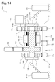
- FIG. 14 is an explanatory diagram of a drive device 110a of Conventional Example 2-1 in which a motor 106 is arranged between two planetary gear mechanisms 111a and 111b arranged coaxially.
- the two planetary gear mechanisms 111a and 111b have an external tooth sun gear 112a and 112b, a plurality of planetary gears 114a and 114b that mesh with the external tooth sun gear 112a and 112b, and a planetary gear 114a, respectively.
- 114b are provided with ring gears 116, 117 having internal teeth that mesh with 114b, and planetary carriers 115a, 115b that rotatably support a plurality of planetary gears 114a, 114b.
- the rotating shaft 108 of the motor 106 projects on both sides and is coupled to the external tooth sun gears 112a and 112b of the planetary gear mechanisms 111a and 111b.
- An intermediate gear 113 is fixed to the rotating shaft 108, the intermediate gear 113 meshes with the drive input gear 130, and the drive input gear 130 meshes with the drive transmission gear 131.
- the rotation of an engine (not shown) is transmitted to the drive transmission gear 131.
- External gears are formed on the outer peripheral surfaces of the ring gears 116 and 117, and are connected to each other so as to rotate in opposite directions via at least one set of first and second auxiliary gear members 118 and 119. ..
- gears 118a and 118b; 119a and 119b are fixed to both ends of the respective shafts, and one of the gears 18a and 19a meshes with the external gears of the ring gears 116 and 117.
- the other gears 18b and 19b mesh with each other and rotate in opposite directions.
- the rotational torque is transmitted from the central shafts 115s and 115t coupled to the planetary carriers 115a and 115b to the wheels 102a and 102b via the constant velocity joint and the drive shaft.
- the external gear of one of the ring gears 117 is configured so that the control gear 105 fixed to the rotating shaft 104a of the control motor 104 meshes with the external gear. (For example, see FIG. 7 and the like in Patent Document 1).
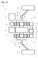
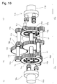
- FIGS. 15 and 16 are explanatory views of the drive device 110 of the conventional example 2-2 in which the motor (not shown) is arranged apart from the two planetary gear mechanisms 111a and 111b arranged coaxially.
- the drive device 110 has substantially the same configuration as the drive device 110a of FIG. 13, but unlike the drive device 110a of FIG. 13, the coupling shaft 112 has two planets.
- the external tooth sun gears 112a and 112b of the gear mechanisms 111a and 111b are coupled.
- An intermediate gear 113 is fixed to the coupling shaft 112, the intermediate gear 113 meshes with the drive input gear 130, and the drive input gear 130 is a drive transmission gear 131 (FIGS. 15 and 15) in which the rotation of a motor or engine (not shown) is transmitted. It meshes with (not shown in FIG. 16) (see FIGS. 1, 2, etc. of Patent Document 1).
- These drive devices 110a and 110 can distribute the rotational torque and control the difference in the rotational speeds of the left and right central axes 115s and 115t. That is, when there is a difference in the rotational torques of the two planetary gear mechanisms 111a and 111b, the two ring gears 116 and 117 rotate in opposite directions. Further, when there is a difference in the rotation speeds of the two central shafts 115s and 115t, the two ring gears 116 and 117 rotate in opposite directions.
- the control motor 104 By appropriately rotating the control motor 104, the difference in the number of rotations of the two central shafts 115s and 115t can be controlled, and the difference in the rotational torque transmitted to the two central shafts 115s and 115t can be controlled. (See, for example, Patent Document 1).
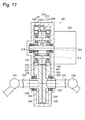
- FIG. 17 is a cross-sectional view of two planetary gear mechanisms 207 and 208 arranged coaxially and a driving device 201 of Conventional Example 3 in which two output shafts are arranged at intervals in the direction perpendicular to the axis.
- the external tooth sun gears 209 and 214 of the planetary gear mechanisms 207 and 208 are coupled to the output shaft 203 of the motor 202.
- External gears 213 and 218 are formed on the planet carriers 211 and 216 of the planetary gear mechanisms 207 and 208 so as to be adjacent to each other.
- the output gears 228 and 235 of the output gear members 226 and 233 mesh with the external gears 213 and 218.
- the output gear members 226 and 233 have shaft portions 227 and 234 corresponding to the output shaft of the drive device 201, and the input shafts 231 of the connecting mechanisms 230 and 237 such as constant velocity joints are formed in the hollow portions of the shaft portions 227 and 234. , 238 are spline-engaged.
- the ring gears 210 and 215 of the planetary gear mechanisms 207 and 208 have external gears formed on their outer peripheral surfaces, and are connected to each other via a differential mechanism 219 similar to that shown in FIGS. 13 to 15. That is, two gears 222, 223; 224, 225 are formed on the first and second shafts 220 and 221 respectively.
- One gear 222, 224 meshes with the external gears of the ring gears 210, 215, the other gear 223, 225 meshes with each other, and the first and second shafts 220, 221 rotate in opposite directions. (See, for example, Patent Document 2).
- the driving force distribution made possible by the conventional example 2-1 and the conventional example 2-2 is an extremely effective control means for the vehicle.
- the motor as the drive source has a higher rotation speed than the internal combustion engine such as a conventional engine, has a large reduction ratio in the process of transmitting to the tire, and has a large moment of inertia (inertia) of the motor. ,growing.
- the moment of inertia of the tire or the like seen from the motor becomes small, and the vehicle becomes unstable due to disturbances such as unevenness of the road surface and friction coefficient.
- Torque vectoring by distribution of driving force has become indispensable for electric units in order to improve vehicle stability and ensure safety.
- torque vectoring by distributing driving force has a great effect even in normal driving such as turning.
- a slip angle In a vehicle, when steering (steering), an angle difference called a slip angle (angle) occurs between the traveling direction of the tire and the rotation direction of the vehicle, and the tire generates a lateral force to try to turn around the center of gravity of the vehicle. There is a difference between the inner and outer wheels of the vehicle. Therefore, it causes a considerable delay in steering and turning of the vehicle. Further, although a large driving force and braking force can be generated in the rotation direction of the tire, a large force cannot be linearly generated in the lateral force perpendicular to the driving force and the braking force. Further, this slip angle also changes greatly depending on not only the steering angle but also the vehicle speed, the load applied to the tires, etc., and is not constant.
- the vehicle can not only turn by the lateral force of the tire due to steering, but also control the driving force of the left and right wheels to generate a rotation difference and turn.
- the response of the vehicle is fast, the slip angle is small, the generation of lateral force is suppressed, stable behavior is exhibited, and stable running is possible.
- torque vectoring that distributes the driving force during steering is performed to achieve high response, suppress the saturation of tire friction due to lateral force, and achieve stable turning. realizable.
- the present invention is suitable for a compact and lightweight electric unit by arranging a rational speed reducer by using a highly rigid gear mechanism for the torque vectoring mechanism that has become indispensable for the electric unit.
- the purpose is to realize a so-called torque vectoring mechanism that realizes a differential mechanism, arranges a control motor, and can distribute driving force, and contributes to the electrification of vehicles.
- the stability of the vehicle is increased, and at low speeds, the minimum turning radius, etc. is reduced, which is convenient for the vehicle.
- the drive devices 110a and 110 of the conventional example 2-1 and the conventional example 2-2 mainly have the following three problems.
- the drive devices 110a and 110 cannot be miniaturized as a whole. This is because the planetary gear mechanisms 111a and 111b and the control motor 104 cannot be miniaturized.
- the planetary carriers 115a and 115b of the two planetary gear mechanisms are connected to the central shafts 115s and 115t, which are axle shafts, respectively.
- the central shafts 115s and 115t are connected to the drive shaft via constant velocity joints, respectively.
- rotational motion and rotational torque are transmitted from the central shafts 115s and 115t of the drive device 110 to the wheels 102a and 102b.
- the planetary carriers 115a and 115b and the central axes 115s and 115t and the wheels 102a and 102b have the same rotational motion and rotational torque.
- the planetary gear mechanisms 111a and 111b are transmitted to the wheels 102a and 102b as in the conventional example 2-1.
- the gear must be strong enough to withstand the high torque. Therefore, the gear modules constituting the planetary gear mechanisms 111a and 111b have to be large, and the planetary gear mechanisms 111a and 111b cannot be miniaturized. Further, the control motor 104 that adds the differential torque to the torque transmitted to the wheels 102a and 102b cannot be miniaturized. Therefore, the entire drive device cannot be miniaturized.
- the planet carriers 115a and 115b are rotatably supported only on the central axes 115s and 115t sides, the planetary carriers 115a and 115b are in a cantilevered state, and the gears and bearings are easily damaged.
- both sides of the planetary carriers 115a and 115b that is, the central axes 115s and 115t sides and the opposite sides are rotatably supported by bearings, the distance between the planetary gear mechanisms 111a and 111b is widened.
- the central shafts 115s and 115t are arranged on both sides of the planetary gear mechanisms 111a and 111b, when the distance between the planetary gear mechanisms 111a and 111b is widened, the central shafts 115s and 115t, which are two output shafts that output rotational torque, It is difficult to reduce the dimension between the tips protruding in opposite directions. Therefore, the width of the drive system becomes wide, and it becomes difficult to construct a vehicle suspension device in which the vehicle travels more stably.
- the drive shaft connecting the central shafts 115s and 115t and the wheels 102a and 102b is short, the camber angle change of the wheels 102a and 102b becomes large with respect to the movement of the bouncing and rebounding wheels, and the unevenness is large. Vehicles become unstable on the road. If the drive shaft is lengthened, the running will be stable. In order to lengthen the drive shaft, the dimensions between the tips of the central shafts 115s and 115t protruding in opposite directions may be reduced. However, as described above, it is difficult to reduce the dimension between the tips of the central axes 115s and 115t protruding in opposite directions, so that it is difficult to construct a vehicle suspension device in which the vehicle travels more stably.
- the reduction ratio between the central shafts 115s and 115t and the ring gears 116 and 117 of the first and second planetary gear mechanisms is extremely small and always 1 or more and 2 or less, and is usually smaller than 1.5. That is, in the planetary gear mechanism, the reduction ratio in the case of carrier output and ring gear input is the number of teeth of the solar wheel / the number of teeth of the ring gear + 1.
- the ring gears 116 and 117 which are connected so as to rotate in opposite directions to each other and constitute a differential, have a small suppression effect due to inertia when a disturbance occurs on the tires of both wheels such as an uneven road surface, and the ring gears 116 and 117 rise sharply. A stress change occurs, and the ring gears 116 and 117 interact with each other, and this change cannot be suppressed unless it is an extremely high-speed control system. That is, in this mechanism, the driving force of the vehicle changes instantaneously and rapidly when straddling, rough roads with irregularities, high speed, etc., so a means for further improving the stability of the vehicle is required.
- the drive device 201 of the conventional example 3 has the following problems.
- the entire drive device 201 is larger than the drive devices 110a and 110 of the conventional example 2-1 and the conventional example 2-2, and the mass of the entire drive device 201 is increased. It cannot be expected to be small and lightweight.
- the drive device 201 is intended to lengthen the drive shaft, and is not intended to reduce the size and weight of the planetary gear mechanisms 207 and 208.
- the drive device 201 needs to secure a core-to-core distance between the input shaft 231 and the motor 202 so as not to interfere with the mounting flange of the motor 202, a bearing (not shown) that supports the input shaft 231 and the like.
- the sum of the outer diameters of the external gears 213 and 218 of the planetary carriers 211 and 216 and the outer diameters of the output gears 228 and 235 of the output gear members 226 and 233 is determined according to the inter-core distance. Further, the external gears 213 and 218 and the output gears 228 and 235 need to mesh with each other without interfering with the differential mechanism 219 that rotates the ring gears 210 and 215 of the planetary gear mechanisms 207 and 208 in opposite directions. Further, when the outer diameters of the output gears 228 and 235 become large, the minimum ground clearance becomes small, and the risk of damage due to collision with a curb or the like increases.
- the size of the outer diameters of the external gears 213 and 218 and the outer diameters of the output gears 228 and 235 there are restrictions on the size of the outer diameters of the external gears 213 and 218 and the outer diameters of the output gears 228 and 235, and the reduction ratio between the external gears 213 and 218 and the output gears 228 and 235 is at most. It is up to 1.2, and even if the planetary gear mechanisms 207 and 208 can be made slightly smaller by adding deceleration, the mass increase due to the additional parts such as the output gear members 226 and 233 and their bearings is the planetary gear mechanism. Overwhelmingly exceeds the mass loss of 207 and 208. Therefore, the drive device 201 cannot be made small and lightweight.
- the drive device 201 has a problem in durability.
- the output gear members 226 and 233 are supported by bearings 229 and 236 only on one side in each axial direction, and are in a cantilever state. Therefore, the output gear members 226 and 233 are more likely to tilt as compared with the case where both sides of the output gear members 226 and 233 in the axial direction are supported by bearings, and the bearings 229 and 236 and the external gears 213 and 218 and the output gears 228 and 235 are easily tilted.
- the external gears 213 and 218 and the output gears 228 and 235 are helical gears, the risk increases as compared with the case of spur gears. Therefore, the drive device 201 has a problem in durability.
- the first problem to be solved by the present invention is that the two planetary gear mechanisms can be miniaturized, the entire drive device can be miniaturized and lightened, and the two output shafts that output rotational torque are in opposite directions. It is an object of the present invention to provide a drive device capable of reducing the dimension between the tips protruding from the tip and further improving the stability of the vehicle, and a second object is to provide a drive device having excellent durability. That is.
- the present invention provides a drive device configured as follows in order to solve the above problems.
- the drive device is a drive device that distributes rotational torque to the left and right wheels of the vehicle, and is (a) an input shaft that is rotationally driven by a drive source, and (b) first and second rotatably supported first and second wheels. An intermediate shaft, (c) rotatably supported first and second output shafts, and (d) first and first rotatably coupled to the input shaft so as to be adjacent to each other in the axial direction. 2.
- the planetary gear mechanism (e) a differential mechanism for evenly distributing the rotational torque to the first and second planetary gear mechanisms, and (f-1) the first from the first planetary gear mechanism.
- a first rotation transmission mechanism that transmits rotation to the intermediate shaft of 1, (f-2) a second rotation transmission mechanism that transmits rotation from the second planetary gear mechanism to the second intermediate shaft, and ( g-1) A first deceleration mechanism that decelerates and transmits rotation from the first intermediate shaft to the first output shaft, and (g-2) the second output shaft from the second intermediate shaft. It is provided with a second deceleration mechanism that decelerates and transmits the rotation.
- the first and second planetary gear mechanisms (i) mesh with the external tooth sun gear fixed to the input shaft and (ii) the external tooth sun gear, and rotate around the external tooth sun gear, respectively.
- a plurality of planetary gears that revolve while rotating, (iii) a hollow tubular ring gear that is rotatably supported and has internal teeth that mesh with the planetary gear, and (iv) support the planetary gear so that it can rotate.
- the planetary carrier has an external gear that is coaxial with the input shaft, is adjacent to the planetary gear in the axial direction, and is an external gear that rotates integrally with the planetary carrier.
- the differential mechanism connects the ring gear of the first planetary gear mechanism and the ring gear of the second planetary gear mechanism so that the ring gears rotate in opposite directions.
- the first rotation transmission mechanism is fixed to the external gear of the planetary carrier of the first planetary gear mechanism and the first intermediate shaft, and has the planetary carrier of the first planetary gear mechanism. It includes a first intermediate gear that meshes with the external gear.
- the second rotation transmission mechanism is fixed to the external gear of the planetary carrier of the second planetary gear mechanism and the second intermediate shaft, and has the planetary carrier of the second planetary gear mechanism. Includes a second intermediate gear that meshes with the external gear.
- the rotational torque input to the input shaft is distributed to the first planetary gear mechanism and the second planetary gear mechanism, and the first planetary gear mechanism, the first rotation transmission mechanism, and the first It is output from the first output shaft via the first reduction mechanism, and is output from the second output shaft via the second planetary gear mechanism, the second rotation transmission mechanism, and the second reduction mechanism.
- the force acting on the gears of the first and second planetary gear mechanisms becomes smaller due to the deceleration by the first and second reduction mechanism, so that the first and second planetary gear mechanisms are made smaller.
- the first and second output shafts are arranged so as to be aligned with the first and second planetary gear mechanisms in the direction perpendicular to the axis, they are arranged on both sides in the axial direction of the first and second planetary gear mechanisms. It is possible to reduce the dimension between the tips of the first and second output shafts protruding in opposite directions from each other.
- the drive device for the tire is more than when the first and second output shafts are coupled to the planetary carriers of the first and second planetary gear mechanisms.
- the moment of inertia on the side becomes large, and fluctuations in the number of rotations of the tire are suppressed.
- On a cobblestone road with large irregularities (Bergian road), there is a concern that the ground contact of the tire will deteriorate and one side or both wheels will rotate at high speed, causing the vehicle to become unstable. Due to the effect of the increase in the moment of inertia, the increase in tire rotation becomes slower, which can further improve the stability of the vehicle.
- the external gear that rotates integrally with the planetary carrier may be formed on a part of the planetary carrier or attached to the planetary carrier.
- the planetary carrier includes a part that functions as an external gear.
- the external gear if the external gear is configured to rotate integrally with the planet carrier, the external gear may be fixed to the planet carrier and the external gear and the planet carrier may not move relative to each other.
- the external gear and the planet carrier may be configured.
- the external gear and the planetary carrier may be able to move relative to each other, for example, the external gear and the planet carrier can move relative to each other in the axial direction.
- the first and second rotation transmission mechanisms can transmit the rotation of the planetary carrier to the first and second intermediate gears by decelerating it, increasing the speed, or transmitting it at the same speed. It is good, but it is preferable to decelerate as described later.
- the differential mechanism may be configured to connect the external teeth formed on the outer peripheral surfaces of the ring gears of the first and second planetary gear mechanisms, or may be inside the ring gears of the first and second planetary gear mechanisms.
- the teeth may be extended and the extended portions of the inner field may be connected to each other, or the ring gears of the first and second planetary gear mechanisms may be connected to each other via a chain, a belt or the like. You may.
- the drive device further includes (h) a rotation control mechanism for transmitting rotational torque from the control motor to either or both of the ring gears of the first and second planetary gear mechanisms.
- the so-called torque vectoring function of distributing the driving force can be realized by controlling the difference between the rotation angles and the driving torques of the first and second output shafts with the control motor.
- the first and second output shafts are arranged coaxially with each other, and one end side facing each other is freely rotationally coupled via the first bearing.
- the distance between the other ends of the first and second output shafts can be made shorter.
- the drive device can be made smaller, and a vehicle suspension device can be configured in which the running of the vehicle is more stable.
- the first and second reduction gears include first and second output gears fixed to the first and second output shafts, respectively.
- the first and second output gears have helical gears whose twist angles are opposite to each other so that the first and second output shafts approach each other during normal driving.
- the axial thrust generated by the driving force being a helical gear suppresses the axial backlash of the first and second output shafts with respect to the first bearing, and the relative rotation thereof. The speed can be suppressed.
- the first and second rotation transmission mechanisms slow down the rotation of the planetary carriers of the first and second planetary gear mechanisms and transmit them to the first and second intermediate shafts. It is composed.
- the efficiency is higher than the case where the speed is increased once by the first and second rotation transmission mechanisms and then decelerated by the first and second reduction mechanisms.
- the planet carriers of the first and second planetary gear mechanisms are adjacent to each other in the axial direction, and are freely rotationally coupled to each other via a second bearing.
- the distance between the planet carriers of the first and second planetary gear mechanisms can be reduced to reduce the size of the drive device.
- the planetary carrier of the first planetary gear mechanism has the external gear on the side opposite to the second planetary gear mechanism, and the planetary carrier of the second planetary gear mechanism has the first planetary gear mechanism.
- the external gear is provided on the side opposite to the planetary gear mechanism of 1.
- the first and second reduction mechanisms are arranged between the first and second rotation transmission mechanisms, and the first and second output shafts are arranged so as to approach each other to drive the vehicle.
- the entire device can be miniaturized.
- the ring gears of the first and second planetary gear mechanisms are coaxial with each other, adjacent to each other in the axial direction, and are freely rotationally coupled to each other via a third bearing.
- the drive device can be miniaturized by reducing the distance between the ring gears of the first and second planetary gear mechanisms.
- the drive device comprises (i-1) a rotating member that rotates by being connected to a member that rotates between the input shaft and the first and second output gears, and (i-2) the rotation. It is further provided with a braking device for stopping the rotation of the member.
- a brake mechanism smaller than that of a normal disc brake provided adjacent to the wheel can be incorporated into the drive device.
- the drive device further includes (j-1) the drive motor as the drive source and (j-2) the control motor. Both the drive motor and the control motor are on the opposite side of the first planetary gear mechanism from the second planetary gear mechanism, or the first planetary gear mechanism of the second planetary gear mechanism. It is placed on the opposite side of.
- the drive motor and the control motor are arranged on the same side in the axial direction of the drive device, and a space is left on the side opposite to the drive motor and the control motor of the drive device. Therefore, the drive device is mounted on the vehicle. Becomes easier.
- the center of the control motor is arranged inside the drive motor.
- the protrusion of the control motor can be reduced or eliminated, and the vehicle can be easily mounted on the vehicle, and the range extender, which is a generator, can be easily arranged.
- the first and second rotation transmission mechanisms and the first and second reduction mechanisms provide the planetary carriers of the first and second planetary gear mechanisms and the first and second output shafts. Since the selectable range of the reduction ratio between them is widened, the two planetary gear mechanisms can be sufficiently miniaturized, and the entire drive device can be miniaturized and lightened. Further, the base ends of the two output shafts that output the rotational torque that are opposed to each other can be arranged so as to be close to each other, and the dimension between the tips of the two output shafts that protrude in opposite directions can be reduced.
- the moment of inertia on the drive device side with respect to the wheels is increased, fluctuations in the wheel rotation speed are suppressed, and the overall width of the drive device can be shortened, so that the suspension device can be used within the limits of the tread of the vehicle. Since the degree of design freedom is increased, the stability of the vehicle can be further improved.
- the support rigidity is improved compared to the cantilever state, so the risk of damage to the bearings and gears is low. Has excellent durability.
- Example 3 It is explanatory drawing of the drive device.
- Example 4 It is explanatory drawing of the drive device.
- Example 5 It is explanatory drawing of the differential mechanism.
- Conventional example 1 It is explanatory drawing of the drive device.
- Conventional Example 2-1 It is explanatory drawing of the drive device.
- Conventional Example 2-2 It is explanatory drawing of the drive device.
- Conventional Example 2-2 It is explanatory drawing of the drive device.
- Example 1 The drive device 10 of the first embodiment will be described with reference to FIGS. 1 to 7.
- FIG. 1 is an explanatory diagram conceptually showing the configuration of the drive device 10.
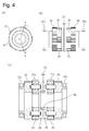
- FIG. 2 is a cross-sectional view of the drive device 10.
- rotational torque is input to the input shaft 12 from the drive motor 70, and the rotational torque is distributed to the first and second output shafts 16 and 17 which are axle shafts.
- the rotational torque is transmitted from the first and second output shafts 16 and 17 to the left and right wheels 6 and 7 via the constant velocity joints 2 and 3 and the drive shafts 4 and 5.
- the drive device 10 includes an input shaft 12, first and first planetary gear mechanisms 20, 21, first and second rotation transmission mechanisms 30, 31, and first and second.
- the second intermediate shafts 14 and 15, the first and second reduction mechanisms and 40 and 41, the first and second output shafts 16 and 17, and the differential mechanism 60 are provided.
- the input shaft 12 is rotatably supported by the main housing 11a via bearings 11x and 11y.
- the first and first planetary gear mechanisms 20 and 21 are coupled to the input shaft 12 so as to be adjacent to each other in the axial direction of the input shaft 12.
- the first and second planetary gear mechanisms 20 and 21 have external tooth sun gears 22 and 23, a plurality of planetary gears 24 and 25, ring gears 26 and 27, and planet carriers 28 and 29, respectively.
- FIG. 3 to 5 are explanatory views of the first and second planetary gear mechanisms 20 and 21.
- FIG. 3A is an explanatory diagram of the ring gears 26 and 27.
- FIG. 3B is an explanation of the meshing of the external tooth sun gears 22 and 23 and the planetary gears 24 and 25, and shows a part of the number of the planetary gears 24 and 25.
- FIG. 4 is an explanatory diagram of planetary carriers 28 and 29.
- 4 (a) is a front view
- FIG. 4 (b) is a side view
- FIG. 4 (c) is a cross-sectional view cut along the line AOA of FIG. 4 (a).
- FIG. 5 is an explanatory diagram of the ring gears 26 and 27.
- 5 (a) is a front view
- FIG. 5 (b) is a side view
- FIG. 5 (c) is a sectional view.
- the external tooth sun gears 22 and 23 are fixed to the input shaft 12, and external teeth 22s and 23s coaxial with the input shaft 12 are formed.
- the planetary gears 24 and 25 are formed with external teeth 24s and 25s that mesh with the external teeth 22s and 23s of the external tooth sun gears 22 and 23.
- the planetary gears 24 and 25 revolve around the external tooth sun gears 22 and 23 in the directions indicated by the arrows 24r and 25r while revolving in the directions indicated by the arrows 22r and 23r. As such, they are rotatably supported by planetary carriers 28, 29 (see FIG. 4C).
- one end side adjacent to each other in the axial direction is freely coupled to each other via a bearing 18r so as to rotate freely.
- the other end side of each is rotatably supported via bearings 32x and 33x.
- the planetary carriers 28 and 29 have external gears 32 and 33 on the other end side, which are external gears coaxial with the input shaft 12 and axially adjacent to the planetary gears 24 and 25.
- the planetary carrier 28 and 29 are rotatably supported.
- the drive device 10 can be miniaturized by arranging the 28 and 29 so as to be close to each other and reducing the distance D1 between the planet carriers 28 and 29.
- the planet carriers 28 and 29 coupled to each other via the bearing 18r need to have high rigidity.
- the relative rotation of the planet carriers 28 and 29 is relatively slow because it occurs corresponding to the difference in the rotation speeds of the output shafts 16 and 17. Therefore, a slide bearing having high rigidity can be used for the bearing 18r interposed between the planet carriers 28 and 29, but when the slide bearing is used, it is preferable to apply a coating such as DLC having a small friction coefficient.
- the ring gears 26 and 27 are hollow tubular members, and the inner teeth 26t and 27t that mesh with the outer teeth 24s and 25s of the planetary gears 24 and 25 on the inner peripheral surface. Is formed, and external teeth 26s and 27s are formed on the outer peripheral surface.
- one end side adjacent to each other in the axial direction is connected to each other freely via bearings 18s, and the other end side thereof is rotatably supported via bearings 26x and 27x. ..
- the ring gears 26 and 27 By coupling one end side of the ring gears 26 and 27 to each other rotatably via bearings 18s, the ring gears 26 and 27 are rotatably supported at both ends by separate bearings.
- the drive device 10 can be miniaturized by arranging the 27s so as to be close to each other and reducing the distance D2 between the ring gears 26 and 27.
- the ring gears 26 and 27 rotate corresponding to the difference in the rotation speeds of the output shafts 16 and 17, and the maximum rotation speed is about 1/100 of the rotation speed of the input shaft 12. Therefore, the bearings 26x and 27x of the ring gears 26 and 27 are sufficient as plain bearings.
- the bearings 26x and 27x are slide bearings, it is preferable to coat the slide bearings with a coating such as DLC having a small friction coefficient.
- bearings 26x and 27x are devised so as not to interfere with the intermediate gears 34 and 35 of the rotation transmission mechanisms 30 and 31 described later when the drive device 10 is assembled.
- the bearings 26x and 27x have smaller diameter portions 26m and 27m that are in sliding contact with the inner peripheral surfaces 26i and 27i on one end side of the ring gears 26 and 27, and are larger than the small diameter portions 26m and 27m. It has large diameter portions 26n and 27n having a large outer diameter.
- the small diameter portions 26m and 27m are O-shaped and continuous in the circumferential direction.
- the large diameter portions 26n and 27n are C-shaped. That is, the intermediate gears 34, which mesh with the external gears 32, 34 with a part of the external gears 32, 34 (see FIG. 4C) of the planetary carriers 28, 29 inserted into the large diameter portions 26n, 27n. A part of the large diameter portions 26n and 27n is cut out in the circumferential direction so that the 35 does not interfere with the large diameter portions 26n and 27n.
- the outer diameter of the outer gears 32, 33 of the planet carriers 28, 29 (that is, the diameter of the tip circle of the outer teeth of the outer gears 32, 33) is the inner diameter of the ring gears 26, 27 (that is, that is, It is made smaller than the diameter of the tip circle of the internal teeth 26t and 27t of the ring gears 26 and 27).
- the rotation transmission mechanisms 30 and 31 can be miniaturized.
- the gears of the first and second planetary gear mechanisms 20 and 21 can also be composed of spur gears, but as shown in FIGS. 1 and 3, helical gears having opposite twist angles may be used. preferable.
- the helical gear has the effect of increasing the meshing ratio, increasing the meshing strength, and suppressing the sound generated during rotation as compared with the case of the spur gear.
- the direction of the torsion angle of the helical gear is determined according to the direction in which the output shafts 16 and 17 rotate during normal driving, that is, when the vehicle advances, for example, each member is shown in the drawing. It is preferable to select the ring gears 26 and 27 so as to approach each other by the axial thrust generated by the helical gear, which rotates in the direction indicated by the arrow in 1 and FIG.
- first and second intermediate shafts 14 and 15 are rotatably supported in parallel with the input shaft 12.
- first and second intermediate shafts 14 and 15 are arranged coaxially, they may be arranged parallel to each other instead of being coaxial.
- first and second intermediate gears 34 and 35 and the first and second input side gears 42 and 43 are fixed to the first and second intermediate shafts 14 and 15. ing.
- One end sides of the first and second intermediate shafts 14 and 15 facing each other are freely coupled to each other via bearings 18q, and the other end sides of the first and second intermediate shafts 14 and 15 are rotatably supported via bearings 19p and 19q. There is.
- the first and second rotation transmission mechanisms 30 and 31 include external gears 32 and 33 that rotate integrally with the planet carriers 28 and 29, and the first and second intermediate shafts 14 and 15 fixed to the first and second intermediate shafts 14 and 15. Includes 2 intermediate gears 34 and 35.
- the first and second intermediate gears 34 and 35 have external teeth 34s and 35s that mesh with the external gears 32 and 33.
- the external gears 32 and 33 and the external teeth 34s and 35s of the first and second intermediate gears 34 and 35 may be spur gears, but may be helical gears as in the first modification described later.
- the first and second output shafts 16 and 17 are rotatably supported in parallel with the input shaft 12.
- the first and second output shafts 16 and 17 are arranged coaxially with each other, and the first and second output gears 44 and 45 are fixed to the first and second output shafts 16 and 17.
- the first and second reduction mechanisms 40 and 41 include first and second input side gears 42 and 43 fixed to the first and second intermediate shafts 14 and 15, and first and second output shafts. It has first and second output gears 44 and 45 fixed to 16 and 17.
- FIG. 6B is an explanatory diagram showing the meshing of the gears. As shown in FIG. 6B, the first and second input side gears 42 and 43 are formed with external teeth 42s and 43s coaxial with the first and second intermediate shafts 14 and 15. The first and second output gears 44 and 45 are formed with external teeth 44s and 45s that mesh with the external teeth 42s and 43s of the first and second first and second input side gears 42 and 43.
- the first and second output shafts 16 and 17 arranged coaxially with each other are connected to each other freely on one end side facing each other via a bearing 18p.
- the first and second output shafts 16 and 17 are rotatably supported on the other end side of the first and second output gears 44 and 45 opposite to the bearing 18p via bearings 19a and 19b. ing.
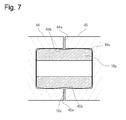
- FIG. 7 is a cross-sectional view of the vicinity of the bearing 18p.
- the bearing 18p is, for example, a hollow cylindrical sliding bearing.
- the bearing 18p may have a solid cylindrical shape.
- the bearing 18p is formed in cylindrical holes 44b, 45b formed coaxially with the first and second output gears 44, 45 on the opposite side surfaces 44a, 45a of the first and second output gears 44, 45. Be placed.
- the bearing 18p may be arranged coaxially with the first and second output shafts 16 and 17 between the first and second output shafts 16 and 17.
- the output gears 44 and 45 may be slightly tilted. Even if the output shafts 16 and 17 are slightly bent, it is possible to prevent an excessive force from acting, which is preferable.
- the other bearings 18q, 18r, 18s may be arranged in the same manner as the bearing 18p, and the corners at both ends in the axial direction may be rounded, or recesses may be formed all around so that the intermediate position in the axial direction is slightly constricted. ..
- the maximum difference in the number of revolutions of the two wheels of the vehicle occurs at low speed and turning with a small radius, and the difference in the number of revolutions is 50 rpm or less, which is very small.
- the occurrence of a large difference in the number of revolutions due to the difference in the friction coefficient of one wheel during vehicle matagi or high-speed driving is a safety problem and should be suppressed. That is, the output shafts 16 and 17 are required not to generate a large difference in rotation speed and not to generate a large difference in rotation speed. Therefore, for the bearing 18p provided between the first and second output gears 44 and 45, a slide bearing having a large load capacity and a friction coefficient larger than that of the ball bearing and having a rotation suppressing effect is preferable.
- both sides of the first and second output gears 44 and 45 in the axial direction are separated.
- the distance D3 between the first and second output gears 44 and 45 can be reduced and the distance between the other ends of the first and second output shafts 16 and 17 can be reduced as compared with the case where the first and second output gears 44 and 45 are rotatably supported. ..
- the drive device 10 can be made smaller, the drive shaft can be made longer, the camper angle can be made smaller, and the vehicle suspension device can be configured in which the running of the vehicle is more stable.
- the external teeth 44s and 45s of the first and second output gears 44 and 45 are rodents. That is, the first and second output gears 44 and 45 have helical gears in which the directions of the twist angles are opposite to each other.
- the directions of the torsional angles of the helical gears of the first and second output gears 44 and 45 are such that the first and second output gears 44 and 45 approach each other when the vehicle moves forward, and the first and second output gears 44 and 45 have the first and second twist angles.
- the output shafts 16 and 17 are brought close to each other. As a result, during normal driving, the axial thrust generated by the helical gear suppresses axial backlash with respect to the bearings 18p of the first and second output shafts 16 and 17, and stabilizes the running of the vehicle. it can.
- the driving force concentrates on the tire having the smaller friction coefficient and the rotation tries to increase.
- part of the kinetic energy becomes a force that causes the output gears 44 and 45 to approach each other due to the effect of the helical gear, and the rise is suppressed by the bearing 18p.
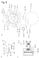
- FIG. 6A is a cross-sectional view of the differential mechanism 60 as viewed along the line AA of FIG. 6B.
- FIG. 6B is an explanatory view showing the meshing of the gears of the drive device 10 as viewed in the axial direction.
- FIG. 6C is an explanatory view of the brake mechanisms 74 and 75.
- the differential mechanism 60 includes first and second differential gear members 62 and 64.
- the first and second differential gear members 62, 64 are rotatably supported via bearings 63a, 63b; 65a, 65b, and mesh with the outer teeth 26s, 27s of the ring gears 26, 27, and other gears 62s, 64s. It has gears 62t and 64t.
- the other gears 62t and 64t mesh with each other and are freely rotationally coupled in opposite directions to each other.
- the differential mechanism 60 causes the ring gears 26 and 27 to rotate in opposite directions.
- the ring gear 26 of the first planetary gear mechanism 20 and the ring gear 27 of the second planetary gear mechanism 21 may be connected so that the ring gears 26 and 27 rotate in opposite directions.
- the differential gear members 62 and 64 may be configured to mesh with the internal teeth 26t and 27t of the ring gears 26 and 27.
- the first planetary gear mechanism 20, the first rotation transmission mechanism 30, and the first deceleration are on one side (left side in FIG. 2) with respect to the virtual surface 10x orthogonal to the input shaft 12.
- the mechanism 40 is arranged, and the second planetary gear mechanism 21, the second rotation transmission mechanism 31, and the second deceleration mechanism 41 are arranged on the other side (right side in FIG. 2).
- the first planetary gear mechanism 20, the first rotation transmission mechanism 30, the first reduction mechanism 40, the second planetary gear mechanism 21, the second rotation transmission mechanism 31, and the second reduction mechanism 41 are virtual. They are arranged symmetrically with respect to the surface 10x. By making the structure symmetrical, the same component can be used and the types of parts can be reduced.
- the mechanism 41 may be arranged substantially symmetrically with respect to the virtual surface 10x. Even when arranged substantially symmetrically, the types of parts can be reduced.
- Symmetry is when the position of the foot of the perpendicular line drawn from the corresponding points on both sides of the virtual surface and the length of the perpendicular line match. Approximately symmetric means that the lengths of the perpendiculars drawn from the corresponding points on both sides of the virtual surface to the virtual surface are the same, but the positions of the legs of the perpendiculars are different, and the vertical lines become symmetric when moved in parallel with the virtual surface.
- first and second intermediate shafts 14 and 15 are not arranged coaxially, if they are arranged substantially symmetrically, the first and second rotation transmission mechanisms 30 and 31 may have the same configuration or the first The first and second reduction mechanisms 40 and 41 may have the same configuration.
- first and second rotation transmission mechanisms 30 and 31 and the first and second rotation transmission mechanisms 30 and 31 may intersect the virtual surface 10x.
- first and second differential gear members 62 and 64 of the differential mechanism 60 are arranged substantially symmetrically with respect to the virtual surface 10x.
- the rotational torque input to the input shaft 12 is distributed to the first planetary gear mechanism 20 and the second planetary gear mechanism 21, and the first planetary gear mechanism 20 and the first rotation transmission mechanism are distributed.
- brake mechanisms 74 and 75 may be provided.
- the brake devices 68k and 69k are connected to one end of the rotating members 68 and 69 that are rotatably supported.
- the rotating members 68 and 69 are rotatably supported and have external teeth 68s and 69s that mesh with the external teeth 34s and 35s of the intermediate gears 34 and 35.
- the number of teeth of the external teeth 68s and 69s of the rotating members 68 and 69 is preferably smaller than that of the external teeth 34s and 35s of the intermediate gears 34 and 35.
- the braking devices 68k and 69k brake the rotation of the rotating members 68 and 69 by using, for example, mechanical frictional force.
- the brake mechanisms 74 and 75 may be appropriately provided in a path through which rotation is transmitted from the input shaft 12 to the output shafts 16 and 17.
- the rotating members 68 and 69 may be configured to mesh with the external gears 32 and 33.
- the brake mechanism may be provided on the input shaft 12 or the first and second intermediate shafts 14 and 15.
- the path through which the rotation from the input shaft 12 to the output shafts 16 and 17 is transmitted is accelerated with respect to the output shafts 16 and 17 representing the rotation of the wheels, resulting in high rotation and low torque. If the 74 and 75 are provided in the path through which the rotation between the input shaft 12 and the output shafts 16 and 17 is transmitted, the torque required for braking can be reduced, and the inboard brake can be configured smaller than the disc brake.
- the inboard brake is a brake provided on the spring, which is a part that moves integrally with the vehicle body, not under the unsprung of the vehicle suspension device.
- brake mechanisms 74 and 75 may be a vehicle braking brake or a parking brake.
- a control gear member 56 is provided as a rotation control mechanism for transmitting rotational torque from the control motor 72.
- the control gear member 56 is rotatably supported and has gears 56a and 56b at both ends.
- One gear 56a of the control gear member 56 meshes with the gear 72a fixed to the rotating shaft of the control motor 72, and the other gear 56b meshes with the external teeth 26s (see FIG. 3A) of the ring gear 26. ..
- control motor 72 the control gear member 56, and the like.
- the first and second planetary gear mechanisms 20 and 21 are reduction gears for solar gear input and carrier output. Unlike a normal planetary gear mechanism, the ring gears 26 and 27 on which the internal teeth 26t and 27t are formed are rotatably supported, and the external teeth 26s and 27s are formed. That is, the first and second planetary gear mechanisms 20 and 21 are 2-input and 1-output gear mechanisms that decelerate and output with respect to the rotation inputs from the sun and the internal teeth.
- the differential mechanism 60 functions as a differential mechanism that absorbs the difference between the inner and outer wheels of the left and right wheels when the vehicle turns.
- the differential mechanism 60 is configured to mesh with the external teeth 26s and 27s of the ring gears 26 and 27 of the first and second planetary gear mechanisms 20 and 21 so that the ring gears 26 and 27 rotate in opposite directions at the same speed. ing. At least one, preferably a plurality (three in the figure) of the differential mechanisms 60 are provided around the ring gears 26 and 27.
- the first and second planetary gear mechanisms 20 and 21 can have the same configuration as spur gears, and can have a symmetrical configuration in the case of helical gears.
- a force acts on the ring gears 26 and 27.
- rotational torques of the same magnitude are output from the first and second planetary gear mechanisms 20 and 21, forces of the same magnitude act on the ring gears 26 and 27.
- the forces acting on the ring gears 26 and 27 are opposite to each other via the differential mechanism 60 and are balanced, so that the ring gears 26 and 27 do not rotate.
- the deceleration by the first and second reduction mechanisms 40 and 41 reduces the force acting on the gears of the first and second planetary gear mechanisms 20 and 21, so that the first and second reduction mechanisms 10 can be used.
- the planetary gear mechanisms 20 and 21 can be miniaturized. By decelerating with the first and second rotation transmission mechanisms 30 and 31, the first and second planetary gear mechanisms 20 and 21 can be further miniaturized.
- the reduction ratio can be made larger than that of one-step deceleration. Since the torque acting on the planetary gear mechanisms 20 and 21 becomes smaller according to the reduction ratio, the planetary gear mechanisms 20 and 21 and the control motor 72 are made smaller than those in the case of one-step deceleration by reducing the speed in two steps. can do.
- the outer diameter of the output gears 44 and 45 coupled to the output shafts 16 and 17 can be made smaller than in the case of the one-step deceleration.
- the planetary gear mechanisms 20 and 21 and the control motor 72 can be reduced, the distance between the cores of the control motor 72 and the drive motor 70 can be reduced, and the protrusion of the drive device 10 can be reduced.
- the mass of the two-stage deceleration portion increases, but the planetary gear mechanisms 20 and 21 and the control motor 72 can be made smaller, and the mass of the planetary gear mechanisms 20 and 21 and the control motor 72 can be reduced. Can be reduced.
- the mass reduced by the planetary gear mechanisms 20 and 21 and the control motor 72 can exceed the mass increased by the two-stage deceleration portion. Therefore, the total mass of the drive device 10 can be reduced by adding the two-stage deceleration.
- the reduction ratio between the planet carriers 28, 29 of the planetary gear mechanisms 20 and 21 and the output shafts 16 and 17 is preferably 1.5 or more, and more preferably 2 or more.
- the reduction ratio between the planetary carrier of the planetary gear mechanism and the output shaft cannot be 1.5 or more.
- the dimensions of the planetary gear mechanisms 20 and 21 are about 1/3 of those of the drive device having only the planetary gear mechanism, and the mass of the planetary gear mechanisms 20 and 21 is about 1/3 as shown below. It becomes 1/10.
- the reduction ratio between the motor and the output shaft is about 10.
- the reduction ratio in the planetary gear mechanism when the external tooth sun gear is input and the planet carrier is output is Zr / Zs + 1 when the number of teeth of the external tooth sun gear is Zs and the number of internal teeth of the ring gear is Zr. is there.
- Zr / Zs + 1 10
- Zr / Zs 9.
- the module of the planetary gear mechanism is, for example, 2.5.
- the rotational torque required for the control motor 72 is only the rotational torque difference between the planetary carriers 28 and 29, and the rotational torque of the drive motor 70. It is small compared to. Moreover, since the reduction mechanism is inserted as compared with the rotational torque of the output shafts 16 and 17, the rotational torque of the drive motor 70 is small. Therefore, the rotational torque required for the control motor 72 may be extremely small as compared with the rotational torque of the output shafts 16 and 17.
- first and second output shafts 16 and 17 are arranged so as to be aligned with the first and second planetary gear mechanisms 20 and 21, both sides of the first and second planetary gear mechanisms 20 and 21 are arranged.
- the dimension between the tips 16p and 17p of the first and second output shafts 16 and 17 can be made smaller than that in the case of being arranged in. Therefore, it is easy to construct a vehicle suspension device in which the drive shaft is lengthened to make the running of the vehicle more stable.
- the distance between the input shaft 12 and the first and second output shafts 16 and 17 can be increased to increase the overall configuration and the vehicle.
- the mounting can be improved.
- a second rotation transmission mechanism 30 and 31 is provided between the first and second rotation transmission mechanisms 30 and 31.
- the first and second reduction mechanisms 40 and 41 can be arranged to reduce the distance between the tips 16p and 17p of the first and second output shafts 16 and 17.
- the drive device 10 can be made smaller, and the drive shafts 4 and 5 between the first and second output shafts 16 and 17 and the left and right wheels 6 and 7 are made longer, so that the vehicle can run more.
- a more stable vehicle suspension device can be configured.
- first and second output shafts 16 and 17 is freely coupled to each other via a bearing 18p, and one end side of the first and second intermediate shafts 14 and 15 is connected.
- bearing 18q Relative rotation free connection to each other via bearing 18q
- relative rotation free connection between one end side of planet carriers 28, 29 via bearing 18r one end side of ring gears 26, 27
- the drive device 10 can be miniaturized even if one end side of each is rotatably supported by a bearing without being rotatably coupled to each other via bearings 18p, 18q, 18r, 18s.
- the first and second planetary gear mechanisms 20 and 21 are as follows.
- the number of external teeth 22s and 23s of the external sun gears 22 and 23 is 23, the number of external teeth 24s and 25s of the planetary gears 24 and 25 is 22, and the number of internal teeth 26t and 27t of the ring gears 26 and 27 is 22.
- 67 Since the input is input to the two external tooth sun gears 22 and 23 and the planet carriers 28 and 29 are the outputs, the reduction ratio is (67/23 + 1) ⁇ 3.913.
- the number of teeth 23 of the planetary gears 24 and 25 includes the number of the planetary gears 24 and 25 arranged 5, the number of teeth 23 of the external coprime gears 22 and 23, and the number of teeth 67 of the internal teeth 26t and 27t of the ring gears 26 and 27. All of them are relatively prime, that is, 23, 67, and 5 have no divisor other than 1. Therefore, the external teeth 24s and 25s of the planetary gears 24 and 25 and the internal teeth 26t and 27t of the ring gears 26 and 27 and the external teeth 22s and 23s of the external tooth sun gears 22 and 23 do not have the same meshing state and are slightly different. The relationship meshes, the sound becomes quieter, and the rotation is transmitted without interruption.
- the output from the planet carriers 28 and 29 is decelerated by the first and second rotation transmission mechanisms 30 and 31 and transmitted to the first and second deceleration mechanisms 40 and 41.
- the number of teeth of the external gears 32 and 33 is 52, and the number of teeth of the external gears 34s and 35s of the intermediate gears 34 and 35 that mesh with the external gears 32 and 33 is 68.
- the modules of the external teeth 34s and 35s of the external gears 32 and 33 and the intermediate gears 34 and 35 are 2. Since the rotation transmission mechanisms 30 and 31 decelerate with respect to the planetary gear mechanisms 20 and 21, the torque to be transmitted increases by the reduction ratio, so that a value larger than the module 1.75 of the planetary gear mechanisms 20 and 21 is required. is there.
- the rotation transmitted to the intermediate gears 34 and 35 is decelerated by the reduction mechanisms 40 and 41, and is transmitted to the output shafts 16 and 17, which is a so-called two-stage deceleration.
- the number of external teeth 42s and 43s of the input side gears 42 and 43 attached to the intermediate shafts 14 and 15 is 27, and the number of external teeth 44s and 45s of the output gears 44 and 45 attached to the output shafts 16 and 17 is 27. Is 49.
- the modules of the external teeth 42s and 43s of the input side gears 42 and 43 and the external teeth 44s and 45s of the output gears 44 and 45 are 2.5.
- the modules became larger in the order of deceleration near the output shafts 16 and 17, which are the final output ends, and the speed was never increased in the process of transmitting the rotation from the drive motor 70 to the output shafts 16 and 17. Therefore, the efficiency is higher than the case where the speed is increased once in the middle and then decelerated.
- the drive device 10 of the specific example includes the first and second rotation transmission mechanisms 30, 31 and the first and second reduction mechanisms 40, 41, whereby the first and second planets are included. Since the gear module of the gear mechanisms 20 and 21 can be made smaller, the first and second rotation transmission mechanisms 30 and 31 and the first and second reduction mechanisms 40 and 41 are added. However, the total mass can be reduced. That is, by decelerating the rotational torque from the drive source and distributing it to the left and right wheels before the rotational torque becomes large, it is possible to add various functional elements and reduce the overall mass. It is a configuration that has been made.
- first and second output shafts 16 and 17 having the same rotation as the left and right wheels 6 and 7 and the ring gears 26 and 27 of the first and second planetary gear mechanisms 20 and 21.
- the moment of inertia on the drive device 10 side with respect to the wheels 6 and 7 is larger than that in the case where the wheels 6 and 7 are rotated. Therefore, the stability of the vehicle can be further improved.
- the ground contact of the tires deteriorates, one side or both wheels may rotate at high speed, and the vehicle may become unstable, but due to this inertia, Since the rotation of the tires increases slowly, the stability of the vehicle is improved even when the control motor 72 does not control the tires.
- the rotation of the left and right wheels can be controlled. Therefore, for example, if a current for holding the rotation is passed through the control motor 72 so as to stop the rotation of the ring gears 26 and 27, the left and right wheels can be controlled. The rotation is the same, and the driving force is not lost.
- the left and right wheels can be controlled by the gear configuration, and compared to the conventional mechanism such as the limited slip differential, there is less friction and the controllability is high.
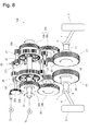
- FIG. 8 is an explanatory diagram of the drive device 10k of the first modification. As shown in FIG. 8, the drive device 10k of the first modification has substantially the same configuration as that of the first embodiment. In the following, the same reference numerals as those in the first embodiment will be used for the same components as in the first embodiment, and the differences from the first embodiment will be mainly described.
- helical gears are often used because they can reduce the noise of the mechanism, increase the meshing rate, and increase the transmission torque.
- helical gears are used for the planetary gear mechanisms 20 and 21 and the first and second reduction mechanisms 40 and 41.
- the first and second reduction gears 40 and 41 are configured so that the meshing of the helical gears generates a thrust force in the direction in which the first and second output gears 44 and 45 approach each other during normal driving. However, the backlash is suppressed.
- the first and second rotation transmission mechanisms 30 and 31 are composed of spur gears, and the first and second intermediate shafts 14 and 15 have the first and second rotation transmission mechanisms 14 and 15.
- the intermediate gears 34 and 35 of the spur gears of the rotation transmission mechanisms 30 and 31 and the input side gears 42 and 43 of the helical gears of the first and second reduction gears 40 and 41 are fixed. Therefore, a thrust force in the direction opposite to that of the output gears 44 and 45 acts on the first and second intermediate shafts 14 and 15, and the backlash of the first and second intermediate shafts 14 and 15 increases.
- the external gears 32k and 33k and the intermediate gears 34k of the first and second rotation transmission mechanisms 30 and 31 are used.
- 35k is a helical gear.
- the twisting directions of the helical gears 34k, 42; 35k, 43 fixed to the intermediate shafts 14 and 15 are opposite to each other like the angle gears.
- one of the two gears 34k and 42; 35k and 43 fixed to the intermediate shafts 14 and 15 has an outer diameter larger than that of the other 42 and 43, so that one of the gears 34k and 35k has a larger outer diameter.
- the twist angle is made smaller than the twist angles of 42 and 43 of the other gear.
- the planetary carriers 28k and 29k of the first and second planetary gear mechanisms 20k and 21k have intermediate gears.
- the thrust force acting on the planetary carriers 28k and 29k by the planetary gears 24 and 25 is in the opposite direction, that is, the thrust in the direction in which the planetary gears 24 and 25 approach each other during normal driving.
- the helical gears of the planetary gear mechanisms 20k and 21k may be configured so that the force acts. With such a configuration, thrust forces in the directions away from each other are generated in the ring gears 26 and 27, and even if there is a difference in the rotational torque distributed to the planetary gear mechanisms 20k and 21k, the thrust force in this direction is always generated. Therefore, the ring gears 26 and 27 do not move. Therefore, the backlash of the ring gears 26 and 27 can be suppressed.
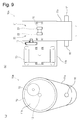
- Example 2 The drive device 10 m of the second embodiment, which is integrally configured by incorporating the drive motor 70 and the control motor 72 into the drive device 10 of the first embodiment, will be described with reference to FIG.
- FIG. 9A is a front view of the drive device 10 m.
- FIG. 9B is a side view of the drive device 10 m.
- the drive motor 70 and the control motor 72 that rotationally drive the input shaft 12 are both on the same side of the drive device 10 m in the axial direction, that is, the first planetary gear mechanism 21 (external teeth).
- the motor housing 11b which is arranged on the opposite side of the second planetary gear mechanism 21 (only the external tooth sun gear 23 is shown) of the sun gear 22 (only the sun gear 22 is shown) and houses the drive motor 70 and the control motor 72, is It is arranged on one side in the axial direction of the main housing 11a that houses the drive device 10.
- the rotation speed of the control motor 72 is relatively large. Further, since the control motor 72 only needs to output the torque that outputs the difference in left-right rotation of the wheels and is decelerating, a maximum output of, for example, 1/50 or less of the maximum output of the drive motor 70 is sufficient. Is.
- a small motor has to have low torque and high rotation speed, but since the control motor 72 has low torque and high rotation speed, it can be miniaturized.
- the control motor 72 has better mountability.
- flat motors such as outer rotor type and coreless flat motors.
- a dual structure motor having an outer rotor and an inner rotor can be used.
- the center of the control motor 72 is arranged inside the drive motor 70 so that the motor housing 11b cannot be projected by the control motor 72.
- the drive device 10 m can be easily mounted on the vehicle.
- the center of the control motor 72 When viewed in the axial direction, the center of the control motor 72 is located inside the drive motor 70, but a part of the control motor 72 may project to the outside of the drive motor 70. In this case, since the protrusion of the control motor 72 is smaller than that in the case where the center of the control motor 72 is arranged outside the drive motor 70, the drive device 10 m can be easily mounted on the vehicle.
- FIG. 10A is an explanatory view of the electric vehicle 80 as viewed from above.
- FIG. 10B is an explanatory view of the electric vehicle 80 as viewed from the side.
- one drive device 10 m of the second embodiment is arranged on each of the front wheel portion and the rear wheel portion. Further, a range extender 86 is arranged on the rear wheel portion.
- the heaviest battery 83 is arranged on a low floor in the center of the vehicle in order to suppress changes in roll and enable stable running.
- the electric vehicle 80 is required to be equipped with a range extender 86, which is a generator, because the convenience is impaired if it takes time to charge the battery 83. Since most generators use fossil fuels, an exhaust pipe 87 is required. Since the exhaust pipe 87 becomes hot, it is difficult to arrange the range extender 86 at the front of the vehicle and connect the exhaust pipe 87 to the rear across the battery 83. Therefore, it is ideal that the range extender 86 is arranged at the rear wheel portion.
- the heat emitted by the range extender 86 can be used as a heat source for heating, which is one of the biggest problems in EV vehicles, and the cruising range is increased by not using the battery 83 as the heat source.
- the main housing 11a for accommodating the drive device 10 having the driving force distribution function for the left and right wheels is arranged in the center of the vehicle, and the drive motor and the control motor are accommodated on one side with respect to the center of the vehicle. Since the motor housing 11b is arranged, the range extender 86 can be arranged on the other side (right side in the traveling direction in the figure), and the drive device 10 m and the range extender 86 can be compatible with each other.
- the steering mechanism 88 must be arranged on the driver side on the front wheel portion. Therefore, the drive device 10m arranged on the front wheel portion is arranged in the center of the vehicle when the main housing 11a is viewed in the traveling direction, and the motor housing 11b is arranged on the side opposite to the steering mechanism 88. Since the motor housing 11b of the drive device 10m is located only on one side of the main housing 11a, a well-balanced and ideal arrangement can be easily realized.
- the battery is arranged in the vehicle center region between the center line of the front wheels 82 and the center line of the rear wheels 84. Further, when the battery 83, which is a heavy object, the drive device 10 within the drive device 10 m, and the range extender 86 are arranged in the center region of the vehicle, running stability such as rolling during turning and pitching during braking can be achieved. Collision safety can be improved.
- the driving force can be distributed to the left and right tires as evenly as possible by the driving device 10 of the driving device 10 m, so that the running stability is improved.
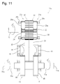
- FIG. 11 is an explanatory diagram of the configuration of the drive device 10a. As shown in FIG. 11, the drive device 10a is configured in substantially the same manner as the drive device 10 of the first embodiment. In the following, the same reference numerals will be used for the parts having the same configuration as that of the first embodiment, and the differences from the first embodiment will be mainly described.
- external tooth sun gears (not shown) of the first and second planetary gear mechanisms 20a and 21a are fixed to the input shaft 12.
- the planetary carriers 28a and 29a that rotatably support the planetary gears 24 and 25 have external gears 32 and 33.
- One end sides of the planet carriers 28a and 29a are rotatably coupled to each other via bearings (not shown), and the other end side is rotatably supported via bearings 28x and 29x.
- the ring gear and the differential mechanism that mesh with the planetary gears 24 and 25 are not shown.
- the external gears 32 and 33 are arranged inside the planet carriers 28a and 29a and are adjacent to each other. That is, in the first embodiment, the planetary carrier 28 of the first planetary gear mechanism 20 has an external gear 32 formed on the side opposite to the second planetary gear mechanism 21, and the planetary carrier 29 of the second planetary gear mechanism 21. Although the external gear 33 is formed on the side opposite to the first planetary gear mechanism 20, in the fourth embodiment, the planet carrier 28a of the first planetary gear mechanism 20a is the second planetary gear mechanism. The external gear 32 is formed on the 21a side, and the planet carrier 29a of the second planetary gear mechanism 21a has the external gear 32 formed on the first planetary gear mechanism 20a side.
- the first and second reduction mechanisms 40 and 41 are arranged between the first and second rotation transmission mechanisms 30 and 31.
- the first and second rotation transmission mechanisms 30 and 31 are arranged between the first and second reduction mechanisms 40 and 41. That is, in the fourth embodiment, the first and second rotation transmission mechanisms 30 and 31 mesh with the external gears 32 and 33 of the planetary carriers 28a and 29a and the intermediate gears 34 and 35 on the outer side in the axial direction.
- the deceleration mechanisms 40 and 41 of the above are arranged.
- first and second output shafts 16a and 17a may be connected to each other freely on one end side via bearings (not shown), or may be connected to each other without being connected to each other. Both sides of the output gears 44 and 45 in the axial direction may be rotatably supported by separate bearings.
- the rotation of the planetary carriers 28a, 29a of the first and second planetary gear mechanisms 20a, 21a is decelerated, and the first and second output shafts 16a, Since it is transmitted to 17a, the first and second planetary gear mechanisms 20a and 21a can be miniaturized.
- the drive device 10a can be made smaller than in the case where the first and second rotation transmission mechanisms 30 and 31 and the first and second reduction mechanisms 40 and 41 are not provided.
- the tips 16q and 17q of the output shafts 16a and 17a project in opposite directions as compared with the case where the first and second rotation transmission mechanisms 30 and 31 and the first and second reduction mechanisms 40 and 41 are not provided. Since the distance between them can be shortened and the drive shaft can be lengthened, it is possible to configure a vehicle suspension device in which the vehicle travels more stably.
- FIG. 12 is an explanatory diagram of the configuration of the drive device 10b.
- the drive device 10b has substantially the same configuration as that of the first embodiment.
- the first and second rotation transmission mechanisms 30 and 31, the first and second reduction mechanisms 40 and 41, and the first and second output shafts 16 and 17 have the same configuration as in the first embodiment. Moreover, the arrangement is the same as that of the first embodiment.
- the first and second planetary gear mechanisms 20b and 21b have different configurations from those of the first embodiment. That is, in the first embodiment, the planet carrier 28 of the first planetary gear mechanism 20 has the external tooth sun gear 22 of the first planetary gear mechanism 20, the planetary gear 24, and the second planetary gear mechanism 21 rather than the ring gear 26. Has an external gear 32 on the opposite side, and the planet carrier 29 of the second planetary gear mechanism 21 is first of the external gear sun gear 23, the planetary gear 25, and the ring gear 27 of the second planetary gear mechanism 21. An external gear 33 is provided on the side opposite to the planetary gear mechanism 20.
- the planet carrier 28b of the first planetary gear mechanism 20b is closer to the second planetary gear mechanism 21b than the external tooth sun gear 22, the planetary gear 24 and the ring gear 26 of the first planetary gear mechanism 20b.
- the planetary carrier 29b of the second planetary gear mechanism 21b has the external gear 32, and is the first planetary gear mechanism than the external tooth sun gear 23, the planetary gear 25, and the ring gear 27 of the second planetary gear mechanism 21b.
- the external gear 33 is provided on the 20b side.
- the distance between the external tooth sun gear 22, the planetary gear 24, and the ring gear 26 of the first planetary gear mechanism 20b and the external tooth sun gear 23, the planetary gear 25, and the ring gear 27 of the second planetary gear mechanism 21b is ,
- the planetary carriers 28b and 29b which are longer than those of the first embodiment and are freely coupled to each other in relative rotation of the first and second planetary gear mechanisms 20b and 21b, and the ring gears of the first and second planetary gear mechanisms 20b and 21b.
- the first and second differential gear members of the differential mechanism 60b that connects 26 and 27 to each other need to be longer in the axial direction than in the first embodiment.
- the drive device 10b of the fifth embodiment includes the external tooth sun gears 22, 23, the planetary gears 24, 25, and the ring gears 26, 27 of the first and second planetary gear mechanisms 20b, 21b, as in the first embodiment.
- the drive device 10b can be made smaller and lighter, though not as much as in the first embodiment, and has excellent durability as in the first embodiment.
- the output shafts 16 and 17 are connected and integrated freely in relative rotation via the bearing 18p.
- the integrated output shafts 16 and 17 are rotatably supported by bearings 19a and 19b arranged on both sides of the output gear members 44 and 45 in the axial direction, and are in a double-sided state.
- the output gear members 226 and 233 are independent of each other, and only one side in each axial direction is supported by the bearings 229 and 236 and is in a cantilever state.
- the support rigidity is higher in the double-sided state than in the cantilever state. Therefore, the drive device 10b of the fifth embodiment has a lower risk of damage to the gears and bearings and is excellent in durability as compared with the third conventional example.
- the external gears 213 and 218 of the planetary carriers 211 and 216 and the output gears 228 and 235 of the output gear members 226 and 233 have one-stage gear meshing. It is not easy to think of changing this to the meshing of two-stage gears.
- the positive effect of making the planetary gear mechanisms 20 and 21 smaller and lighter by adding deceleration due to gear meshing has a negative effect such as an increase in mass and dimensions due to the addition of deceleration due to gear meshing. It is an unpredictable and remarkable effect that the entire drive device 10b can be made smaller and lighter as a result.
- the drive device 10b of the fifth embodiment has a creative configuration that even a person skilled in the art cannot think of.
- the planetary carriers of the first and second planetary gear mechanisms and the first and second deceleration mechanisms are provided by the first and second rotation transmission mechanisms and the first and second reduction mechanisms. Since the selectable range of the reduction ratio between the output shaft and the output shaft is widened, the two planetary gear mechanisms can be sufficiently miniaturized, and the entire drive device can be miniaturized and lightened. Further, the base ends of the two output shafts that output the rotational torque that are opposed to each other can be arranged so as to be close to each other, and the dimension between the tips of the two output shafts that protrude in opposite directions can be reduced.
- the moment of inertia on the drive device side with respect to the wheels is increased, fluctuations in the wheel rotation speed are suppressed, and the overall width of the drive device can be shortened, so that the suspension device can be used within the limits of the tread of the vehicle. Since the degree of design freedom is increased, the stability of the vehicle can be further improved.
- the support rigidity is improved compared to the cantilever state, so the risk of damage to the bearings and gears is low, and durability is low. Excellent in sex.
- the rotational torque is distributed by the two planetary gear mechanisms, and the rotational torque is output from the first and second output shafts via the first and second rotational transmission mechanisms and the first and second deceleration mechanisms.
- a vehicle drive device that is lightweight and has a differential mechanism.
- a so-called torque vectoring mechanism capable of distributing the driving force can be realized, which can contribute to the electrification of the vehicle.
- the stability of the vehicle is increased, and at low speeds, the minimum turning radius, etc. is reduced, which is convenient for the vehicle.
- an electric unit suitable for vehicle control required by society in recent years such as self-propelled driving and collision avoidance.
- the present invention is not limited to the above embodiment, and can be implemented with various modifications.
- the drive motor may be arranged on one side in the axial direction of the drive device, and the control motor may be arranged on the other side.
- the gears of the first and second rotation transmission mechanisms, the first and second reduction gears, and the differential mechanism are composed of gears other than spur gears and helical gears, for example, bevel gears and face gears. You may.
Landscapes
- Engineering & Computer Science (AREA)
- Mechanical Engineering (AREA)
- Chemical & Material Sciences (AREA)
- Combustion & Propulsion (AREA)
- Transportation (AREA)
- General Engineering & Computer Science (AREA)
- Retarders (AREA)
- Obtaining Desirable Characteristics In Audible-Bandwidth Transducers (AREA)
- Soundproofing, Sound Blocking, And Sound Damping (AREA)
Abstract
La présente invention concerne un dispositif d'entraînement permettant de réduire la taille d'un mécanisme d'engrenage planétaire, réduire la taille et le poids de l'ensemble du dispositif d'entraînement, réduire la dimension entre les extrémités de pointe d'un arbre de sortie pour délivrer en sortie un couple de rotation, lesdites extrémités de pointe faisant saillie dans des directions opposées l'une à l'autre, et encore améliorer la stabilité du véhicule. Des planétaires externes (22, 23) sont accouplés à un arbre d'entrée (12). Des porte-satellites (28, 29) sont coaxiaux avec l'arbre d'entrée (12), sont adjacents aux porte-satellites (24, 25) dans leur direction axiale et présentent des engrenages externes (32, 33) qui tournent ensemble avec les porte-satellites (28, 29). Des couronnes (26, 27) qui s'engrènent respectivement avec les porte-satellites (28, 29) sont supportées en rotation et tournent dans des directions mutuellement opposées au moyen d'un mécanisme différentiel (60). Des engrenages intermédiaires (34, 35) et des engrenages côté entrée (42, 43) sont respectivement fixés à des arbres intermédiaires (14, 15), lesdits engrenages intermédiaires (34, 35) s'engrenant respectivement avec les engrenages externes (32, 33). Des engrenages de sortie (44, 45) qui s'engrènent respectivement avec les engrenages côté entrée (42, 43) sont respectivement fixés à des arbres de sortie (16, 17).
Priority Applications (3)
| Application Number | Priority Date | Filing Date | Title |
|---|---|---|---|
| CN201980097285.6A CN113950591B (zh) | 2019-06-10 | 2019-09-09 | 车辆的驱动装置以及电动汽车 |
| US17/617,407 US12103383B2 (en) | 2019-06-10 | 2019-09-09 | Vehicular drive device, and electric vehicle |
| JP2021525895A JP7057038B2 (ja) | 2019-06-10 | 2019-09-09 | 車両の駆動装置及び電気自動車 |
Applications Claiming Priority (2)
| Application Number | Priority Date | Filing Date | Title |
|---|---|---|---|
| JP2019107702 | 2019-06-10 | ||
| JP2019-107702 | 2019-06-10 |
Publications (1)
| Publication Number | Publication Date |
|---|---|
| WO2020250453A1 true WO2020250453A1 (fr) | 2020-12-17 |
Family
ID=73781034
Family Applications (1)
| Application Number | Title | Priority Date | Filing Date |
|---|---|---|---|
| PCT/JP2019/035422 Ceased WO2020250453A1 (fr) | 2019-06-10 | 2019-09-09 | Dispositif d'entraînement de véhicule et véhicule électrique |
Country Status (4)
| Country | Link |
|---|---|
| US (1) | US12103383B2 (fr) |
| JP (1) | JP7057038B2 (fr) |
| CN (1) | CN113950591B (fr) |
| WO (1) | WO2020250453A1 (fr) |
Cited By (2)
| Publication number | Priority date | Publication date | Assignee | Title |
|---|---|---|---|---|
| CN112797133A (zh) * | 2021-01-15 | 2021-05-14 | 中国铁建重工集团股份有限公司 | 一种青贮机割台变速箱及青贮机 |
| EP4306347A1 (fr) * | 2022-07-12 | 2024-01-17 | Toyota Jidosha Kabushiki Kaisha | Appareil d'entraînement |
Families Citing this family (3)
| Publication number | Priority date | Publication date | Assignee | Title |
|---|---|---|---|---|
| US11628713B2 (en) * | 2020-06-04 | 2023-04-18 | Rivian Ip Holdings, Llc | Electric vehicle powertrain assembly having nested shafts |
| CN117048322A (zh) * | 2022-05-06 | 2023-11-14 | 莫嘉林 | 汽车动力分配器 |
| JP2025116471A (ja) * | 2024-01-29 | 2025-08-08 | 株式会社Soken | 関節車輪機構 |
Citations (3)
| Publication number | Priority date | Publication date | Assignee | Title |
|---|---|---|---|---|
| JP2007276760A (ja) * | 2006-03-10 | 2007-10-25 | Nissan Motor Co Ltd | 駆動力配分装置 |
| JP2010190287A (ja) * | 2009-02-17 | 2010-09-02 | Honda Motor Co Ltd | 差動装置の駆動力配分機構 |
| JP2017145914A (ja) * | 2016-02-18 | 2017-08-24 | トヨタ自動車株式会社 | 動力伝達装置 |
Family Cites Families (11)
| Publication number | Priority date | Publication date | Assignee | Title |
|---|---|---|---|---|
| JPH05332405A (ja) * | 1992-05-25 | 1993-12-14 | Toyota Motor Corp | 電気自動車用減速機 |
| CA2259771C (fr) * | 1998-02-19 | 2003-04-01 | Hitachi, Ltd. | Transmission, ainsi que vehicule et bicyclette utilisant cette transmission |
| JP2002104001A (ja) * | 2000-09-29 | 2002-04-09 | Exedy Corp | 電気自動車の減速装置及びその減速比設定方法 |
| JP2002235832A (ja) * | 2001-02-13 | 2002-08-23 | Exedy Corp | 減速機付き差動装置 |
| JP5276572B2 (ja) * | 2009-11-19 | 2013-08-28 | 株式会社小松製作所 | 作業用車両の終減速装置 |
| JP5867104B2 (ja) * | 2012-01-17 | 2016-02-24 | アイシン精機株式会社 | 車両駆動装置 |
| JP2014025495A (ja) * | 2012-07-24 | 2014-02-06 | Nsk Ltd | 電気自動車用駆動装置 |
| WO2015008325A1 (fr) | 2013-07-16 | 2015-01-22 | 株式会社アルケミカ | Dispositif d'engrenage d'entraînement |
| JP6475188B2 (ja) * | 2016-04-28 | 2019-02-27 | トヨタ自動車株式会社 | 駆動装置 |
| JP6445091B2 (ja) * | 2017-05-26 | 2018-12-26 | 本田技研工業株式会社 | 動力装置 |
| EP3679276A4 (fr) * | 2017-09-08 | 2021-03-24 | Chu, Shaun | Système différentiel comprenant des engrenages planétaires étagés à vitesse différentielle gouvernés par un moteur à vitesse variable et procédé de fonctionnement associé |
-
2019
- 2019-09-09 WO PCT/JP2019/035422 patent/WO2020250453A1/fr not_active Ceased
- 2019-09-09 US US17/617,407 patent/US12103383B2/en active Active
- 2019-09-09 CN CN201980097285.6A patent/CN113950591B/zh active Active
- 2019-09-09 JP JP2021525895A patent/JP7057038B2/ja active Active
Patent Citations (3)
| Publication number | Priority date | Publication date | Assignee | Title |
|---|---|---|---|---|
| JP2007276760A (ja) * | 2006-03-10 | 2007-10-25 | Nissan Motor Co Ltd | 駆動力配分装置 |
| JP2010190287A (ja) * | 2009-02-17 | 2010-09-02 | Honda Motor Co Ltd | 差動装置の駆動力配分機構 |
| JP2017145914A (ja) * | 2016-02-18 | 2017-08-24 | トヨタ自動車株式会社 | 動力伝達装置 |
Cited By (2)
| Publication number | Priority date | Publication date | Assignee | Title |
|---|---|---|---|---|
| CN112797133A (zh) * | 2021-01-15 | 2021-05-14 | 中国铁建重工集团股份有限公司 | 一种青贮机割台变速箱及青贮机 |
| EP4306347A1 (fr) * | 2022-07-12 | 2024-01-17 | Toyota Jidosha Kabushiki Kaisha | Appareil d'entraînement |
Also Published As
| Publication number | Publication date |
|---|---|
| JP7057038B2 (ja) | 2022-04-19 |
| CN113950591A (zh) | 2022-01-18 |
| JPWO2020250453A1 (fr) | 2020-12-17 |
| CN113950591B (zh) | 2023-08-25 |
| US20220242229A1 (en) | 2022-08-04 |
| US12103383B2 (en) | 2024-10-01 |
Similar Documents
| Publication | Publication Date | Title |
|---|---|---|
| JP7057038B2 (ja) | 車両の駆動装置及び電気自動車 | |
| US8784248B2 (en) | Engine start control device of hybrid vehicle | |
| JP5725197B2 (ja) | ハイブリッド車両用駆動装置 | |
| CN103459181B (zh) | 用于能电驱动的车辆的用来驱动车轮的驱动装置 | |
| CN106555844B (zh) | 动力驱动系统及具有其的车辆 | |
| US20130023372A1 (en) | Power transmission device | |
| US9440531B2 (en) | Electric power train for the steerable axle of a motor vehicle | |
| CN106553526B (zh) | 动力驱动系统及具有其的车辆 | |
| US20130024062A1 (en) | Drive control device of hybrid vehicle | |
| CN104024014B (zh) | 车辆用动力传递装置 | |
| JP5349988B2 (ja) | 電気自動車用駆動システム | |
| CN103153665A (zh) | 混合动力车辆用驱动装置 | |
| WO2012086036A1 (fr) | Dispositif de transmission de puissance pour véhicule | |
| CN106553537B (zh) | 动力驱动系统及具有其的车辆 | |
| CN105793083B (zh) | 车辆用驱动装置 | |
| JP2018065402A (ja) | インホイールモータ駆動装置 | |
| CN106555858B (zh) | 动力驱动系统及具有其的车辆 | |
| JP2014024412A (ja) | 車両用駆動装置 | |
| KR102654447B1 (ko) | 토크 벡터링 장치 | |
| US20180209518A1 (en) | Vehicle | |
| JP3855905B2 (ja) | ハイブリッド車の駆動装置 | |
| JP2012236579A (ja) | ハイブリッド車両用駆動装置 | |
| CN106555854B (zh) | 动力驱动系统及具有其的车辆 | |
| CN106553528B (zh) | 动力驱动系统及具有其的车辆 | |
| US11248693B2 (en) | Vehicle gear |
Legal Events
| Date | Code | Title | Description |
|---|---|---|---|
| 121 | Ep: the epo has been informed by wipo that ep was designated in this application |
Ref document number: 19932466 Country of ref document: EP Kind code of ref document: A1 |
|
| ENP | Entry into the national phase |
Ref document number: 2021525895 Country of ref document: JP Kind code of ref document: A |
|
| NENP | Non-entry into the national phase |
Ref country code: DE |
|
| 122 | Ep: pct application non-entry in european phase |
Ref document number: 19932466 Country of ref document: EP Kind code of ref document: A1 |