WO2020255330A1 - Système convertisseur de puissance - Google Patents
Système convertisseur de puissance Download PDFInfo
- Publication number
- WO2020255330A1 WO2020255330A1 PCT/JP2019/024494 JP2019024494W WO2020255330A1 WO 2020255330 A1 WO2020255330 A1 WO 2020255330A1 JP 2019024494 W JP2019024494 W JP 2019024494W WO 2020255330 A1 WO2020255330 A1 WO 2020255330A1
- Authority
- WO
- WIPO (PCT)
- Prior art keywords
- power
- power supply
- converter
- power conversion
- control unit
- Prior art date
- Legal status (The legal status is an assumption and is not a legal conclusion. Google has not performed a legal analysis and makes no representation as to the accuracy of the status listed.)
- Ceased
Links
Images


Classifications
-
- H—ELECTRICITY
- H02—GENERATION; CONVERSION OR DISTRIBUTION OF ELECTRIC POWER
- H02J—ELECTRIC POWER NETWORKS; CIRCUIT ARRANGEMENTS OR SYSTEMS FOR SUPPLYING OR DISTRIBUTING ELECTRIC POWER; SYSTEMS FOR STORING ELECTRIC ENERGY
- H02J7/00—Circuit arrangements for charging or discharging batteries or for supplying loads from batteries
- H02J7/34—Parallel operation in networks using both storage and other DC sources, e.g. providing buffering
- H02J7/342—The other DC source being a battery actively interacting with the first one, i.e. battery to battery charging
-
- H—ELECTRICITY
- H02—GENERATION; CONVERSION OR DISTRIBUTION OF ELECTRIC POWER
- H02M—APPARATUS FOR CONVERSION BETWEEN AC AND AC, BETWEEN AC AND DC, OR BETWEEN DC AND DC, AND FOR USE WITH MAINS OR SIMILAR POWER SUPPLY SYSTEMS; CONVERSION OF DC OR AC INPUT POWER INTO SURGE OUTPUT POWER; CONTROL OR REGULATION THEREOF
- H02M1/00—Details of apparatus for conversion
- H02M1/0003—Details of control, feedback or regulation circuits
- H02M1/0006—Arrangements for supplying an adequate voltage to the control circuit of converters
-
- H—ELECTRICITY
- H02—GENERATION; CONVERSION OR DISTRIBUTION OF ELECTRIC POWER
- H02M—APPARATUS FOR CONVERSION BETWEEN AC AND AC, BETWEEN AC AND DC, OR BETWEEN DC AND DC, AND FOR USE WITH MAINS OR SIMILAR POWER SUPPLY SYSTEMS; CONVERSION OF DC OR AC INPUT POWER INTO SURGE OUTPUT POWER; CONTROL OR REGULATION THEREOF
- H02M1/00—Details of apparatus for conversion
- H02M1/0003—Details of control, feedback or regulation circuits
- H02M1/0032—Control circuits allowing low power mode operation, e.g. in standby mode
-
- H—ELECTRICITY
- H02—GENERATION; CONVERSION OR DISTRIBUTION OF ELECTRIC POWER
- H02M—APPARATUS FOR CONVERSION BETWEEN AC AND AC, BETWEEN AC AND DC, OR BETWEEN DC AND DC, AND FOR USE WITH MAINS OR SIMILAR POWER SUPPLY SYSTEMS; CONVERSION OF DC OR AC INPUT POWER INTO SURGE OUTPUT POWER; CONTROL OR REGULATION THEREOF
- H02M3/00—Conversion of DC power input into DC power output
-
- H—ELECTRICITY
- H02—GENERATION; CONVERSION OR DISTRIBUTION OF ELECTRIC POWER
- H02M—APPARATUS FOR CONVERSION BETWEEN AC AND AC, BETWEEN AC AND DC, OR BETWEEN DC AND DC, AND FOR USE WITH MAINS OR SIMILAR POWER SUPPLY SYSTEMS; CONVERSION OF DC OR AC INPUT POWER INTO SURGE OUTPUT POWER; CONTROL OR REGULATION THEREOF
- H02M3/00—Conversion of DC power input into DC power output
- H02M3/02—Conversion of DC power input into DC power output without intermediate conversion into AC
- H02M3/04—Conversion of DC power input into DC power output without intermediate conversion into AC by static converters
- H02M3/10—Conversion of DC power input into DC power output without intermediate conversion into AC by static converters using discharge tubes with control electrode or semiconductor devices with control electrode
- H02M3/145—Conversion of DC power input into DC power output without intermediate conversion into AC by static converters using discharge tubes with control electrode or semiconductor devices with control electrode using devices of a triode or transistor type requiring continuous application of a control signal
- H02M3/155—Conversion of DC power input into DC power output without intermediate conversion into AC by static converters using discharge tubes with control electrode or semiconductor devices with control electrode using devices of a triode or transistor type requiring continuous application of a control signal using semiconductor devices only
- H02M3/156—Conversion of DC power input into DC power output without intermediate conversion into AC by static converters using discharge tubes with control electrode or semiconductor devices with control electrode using devices of a triode or transistor type requiring continuous application of a control signal using semiconductor devices only with automatic control of output voltage or current, e.g. switching regulators
- H02M3/158—Conversion of DC power input into DC power output without intermediate conversion into AC by static converters using discharge tubes with control electrode or semiconductor devices with control electrode using devices of a triode or transistor type requiring continuous application of a control signal using semiconductor devices only with automatic control of output voltage or current, e.g. switching regulators including plural semiconductor devices as final control devices for a single load
-
- H—ELECTRICITY
- H02—GENERATION; CONVERSION OR DISTRIBUTION OF ELECTRIC POWER
- H02J—ELECTRIC POWER NETWORKS; CIRCUIT ARRANGEMENTS OR SYSTEMS FOR SUPPLYING OR DISTRIBUTING ELECTRIC POWER; SYSTEMS FOR STORING ELECTRIC ENERGY
- H02J2105/00—Networks for supplying or distributing electric power characterised by their spatial reach or by the load
- H02J2105/30—Networks for supplying or distributing electric power characterised by their spatial reach or by the load the load networks being external to vehicles, i.e. exchanging power with vehicles
- H02J2105/33—Networks for supplying or distributing electric power characterised by their spatial reach or by the load the load networks being external to vehicles, i.e. exchanging power with vehicles exchanging power with road vehicles
- H02J2105/37—Networks for supplying or distributing electric power characterised by their spatial reach or by the load the load networks being external to vehicles, i.e. exchanging power with vehicles exchanging power with road vehicles exchanging power with electric vehicles [EV] or with hybrid electric vehicles [HEV]
-
- H—ELECTRICITY
- H02—GENERATION; CONVERSION OR DISTRIBUTION OF ELECTRIC POWER
- H02J—ELECTRIC POWER NETWORKS; CIRCUIT ARRANGEMENTS OR SYSTEMS FOR SUPPLYING OR DISTRIBUTING ELECTRIC POWER; SYSTEMS FOR STORING ELECTRIC ENERGY
- H02J2207/00—Details of circuit arrangements for charging or discharging batteries or supplying loads from batteries
- H02J2207/10—Control circuit supply, e.g. means for supplying power to the control circuit
-
- H—ELECTRICITY
- H02—GENERATION; CONVERSION OR DISTRIBUTION OF ELECTRIC POWER
- H02J—ELECTRIC POWER NETWORKS; CIRCUIT ARRANGEMENTS OR SYSTEMS FOR SUPPLYING OR DISTRIBUTING ELECTRIC POWER; SYSTEMS FOR STORING ELECTRIC ENERGY
- H02J2207/00—Details of circuit arrangements for charging or discharging batteries or supplying loads from batteries
- H02J2207/20—Charging or discharging characterised by the power electronics converter
-
- H—ELECTRICITY
- H02—GENERATION; CONVERSION OR DISTRIBUTION OF ELECTRIC POWER
- H02M—APPARATUS FOR CONVERSION BETWEEN AC AND AC, BETWEEN AC AND DC, OR BETWEEN DC AND DC, AND FOR USE WITH MAINS OR SIMILAR POWER SUPPLY SYSTEMS; CONVERSION OF DC OR AC INPUT POWER INTO SURGE OUTPUT POWER; CONTROL OR REGULATION THEREOF
- H02M3/00—Conversion of DC power input into DC power output
- H02M3/22—Conversion of DC power input into DC power output with intermediate conversion into AC
- H02M3/24—Conversion of DC power input into DC power output with intermediate conversion into AC by static converters
- H02M3/28—Conversion of DC power input into DC power output with intermediate conversion into AC by static converters using discharge tubes with control electrode or semiconductor devices with control electrode to produce the intermediate AC
- H02M3/325—Conversion of DC power input into DC power output with intermediate conversion into AC by static converters using discharge tubes with control electrode or semiconductor devices with control electrode to produce the intermediate AC using devices of a triode or a transistor type requiring continuous application of a control signal
- H02M3/335—Conversion of DC power input into DC power output with intermediate conversion into AC by static converters using discharge tubes with control electrode or semiconductor devices with control electrode to produce the intermediate AC using devices of a triode or a transistor type requiring continuous application of a control signal using semiconductor devices only
-
- Y—GENERAL TAGGING OF NEW TECHNOLOGICAL DEVELOPMENTS; GENERAL TAGGING OF CROSS-SECTIONAL TECHNOLOGIES SPANNING OVER SEVERAL SECTIONS OF THE IPC; TECHNICAL SUBJECTS COVERED BY FORMER USPC CROSS-REFERENCE ART COLLECTIONS [XRACs] AND DIGESTS
- Y02—TECHNOLOGIES OR APPLICATIONS FOR MITIGATION OR ADAPTATION AGAINST CLIMATE CHANGE
- Y02T—CLIMATE CHANGE MITIGATION TECHNOLOGIES RELATED TO TRANSPORTATION
- Y02T10/00—Road transport of goods or passengers
- Y02T10/60—Other road transportation technologies with climate change mitigation effect
- Y02T10/70—Energy storage systems for electromobility, e.g. batteries
-
- Y—GENERAL TAGGING OF NEW TECHNOLOGICAL DEVELOPMENTS; GENERAL TAGGING OF CROSS-SECTIONAL TECHNOLOGIES SPANNING OVER SEVERAL SECTIONS OF THE IPC; TECHNICAL SUBJECTS COVERED BY FORMER USPC CROSS-REFERENCE ART COLLECTIONS [XRACs] AND DIGESTS
- Y02—TECHNOLOGIES OR APPLICATIONS FOR MITIGATION OR ADAPTATION AGAINST CLIMATE CHANGE
- Y02T—CLIMATE CHANGE MITIGATION TECHNOLOGIES RELATED TO TRANSPORTATION
- Y02T10/00—Road transport of goods or passengers
- Y02T10/80—Technologies aiming to reduce greenhouse gasses emissions common to all road transportation technologies
- Y02T10/92—Energy efficient charging or discharging systems for batteries, ultracapacitors, supercapacitors or double-layer capacitors specially adapted for vehicles
Definitions
- This application relates to a power conversion system.
- a lead battery mounted on a vehicle in order to drive these electric parts In some cases, electric power is mainly obtained from a low-voltage battery (hereinafter referred to as a low-voltage battery), and internal electric power is generated as a power supply source and supplied to each function.
- a low-voltage battery hereinafter referred to as a low-voltage battery
- the efficiency of the auxiliary power source for operating the power converter itself in addition to the power conversion efficiency, and further suppress the standby power.
- the efficiency (loss) of the auxiliary power supply cannot be ignored when looking at the loss ratio of the entire power component.
- Patent Document 1 discloses that a current supply circuit capable of reducing dark current or power consumption is provided. That is, in such a current supply circuit, a power supply circuit that supplies a current having the same magnitude as the reference current generated based on the power supply voltage to another circuit, and a fluctuation of the power supply voltage are predicted based on the load state.
- the power supply fluctuation prediction means and the reference current variable means for changing the magnitude of the reference current when the fluctuation of the power supply voltage is predicted
- the power supply voltage of the power supply unit can be changed by the power supply fluctuation prediction means. Only when predicted, the reference current variable means make the reference current larger than usual. Thereby, it is possible to provide a current supply circuit capable of reducing dark current or power consumption.
- Patent Document 2 discloses an auxiliary power supply device that can eliminate the need for an auxiliary battery that supplies standby power to an auxiliary machine. That is, the power converter that converts the power from the main power source and outputs it to the auxiliary machine, and the normal operation or standby state of the auxiliary machine are determined according to the operating or stopped state of the system, and when the auxiliary machine is in the standby state, the above The power converter is controlled so that the power from the main power source is converted into the standby voltage, and the power conversion is performed so that the power from the main power source is converted into the normal operating voltage when the auxiliary machine is in the normal operating state. It is equipped with a control device that controls the device. As a result, electric power can be supplied to the auxiliary machine without using the auxiliary machine battery.
- the normal operating voltage is larger than the standby voltage.
- the power converter converts the power from the main power supply and supplies it to the auxiliary machine not only in the normal operating state but also in the standby state, the auxiliary battery is not required. Then, it is disclosed that the power consumption is effectively reduced by optimally controlling the auxiliary machine voltage supplied in the auxiliary machine state.
- Patent Document 1 In order to cut the standby power, in Patent Document 1, an ignition switch exists between the power supply unit and the current supply circuit, and the standby power when the circuit itself is stopped can be obtained by opening and closing the ignition switch. The method of shutting off has become common, and there is a problem that the standby power cannot be effectively reduced.
- the present application discloses a technique for solving the above-mentioned problems, and DC / DC by controlling the supply or stop of the power supply by the power supply function while the DC / DC converter is stopped.
- the purpose is to suppress standby power in the power supply or control unit of the converter.
- the power conversion system disclosed in the present application includes a DC / DC converter for charging a battery and a power conversion device including at least one of an inverter or a converter.
- the DC / DC converter supplies power to a power conversion unit that converts an input voltage into a required voltage, a first control unit that drives the power conversion unit, and the first control unit, and also supplies the DC / DC.
- It is equipped with a power supply device that uses the output of a converter or the battery as a power supply source, and a power supply function for controlling the power supply to the power supply device.
- the power supply function is such that the power supply is controlled by the second control unit of the power conversion device while the DC / DC converter is on standby.
- the DC / DC converter supplies power to a power conversion unit that converts an input voltage into a required voltage, a first control unit that drives the power conversion unit, and the first control unit, and also supplies the DC / DC. It is equipped with a power supply device that uses the output of a converter or the battery as a power supply source. Further, the power supply device is provided with a power supply device output ON / OFF function for instructing output permission and output stop, and the power supply device output ON / OFF function is a second control of the power conversion device while the DC / DC converter is on standby. The power supply is controlled by the unit.
- the DC / DC converter is connected to the battery by controlling the power supply from another power conversion device and controlling the power supply by the power supply function while the operation is stopped. Standby power in the power supply unit or control unit of the DC / DC converter can be suppressed.
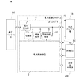
- FIG. It is a block diagram which shows the basic structure of the power conversion system according to Embodiment 1.
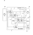
- FIG. It is a block diagram which shows the structure of the power conversion system by Embodiment 1.
- FIG. It is a block diagram which shows the structure of the power conversion system according to Embodiment 2.
- Embodiment 1 relates to a standby power reduction system for a control power supply circuit in a power conversion device in which a plurality of components such as an inverter and a converter in the field of power electronics are integrally formed.
- FIG. 1 is a block diagram showing a basic configuration of a power conversion system according to the present embodiment.
- the power conversion system includes a DC / DC converter 1 for charging the low-voltage battery 100 and another power conversion device 2 composed of a plurality of inverters or converters. That is, the power conversion device 2 includes at least one of an inverter or a converter.
- the DC / DC converter 1 includes a power conversion unit 3, a control unit (first control unit) 4, and a power supply device 5.
- the power conversion unit 3 converts the input voltage into a desired voltage.
- the control unit 4 drives the power conversion unit 3.
- the power supply device 5 supplies electric power to the control unit 4.
- the power supply device 5 uses the output of the DC / DC converter 1 itself or the low-voltage battery 100 as a power supply source, and is provided with a power supply function 6 for controlling the supply or stop of the power supply.
- the DC / DC converter 1 for charging the low-voltage battery 100 and the other power conversion device 2 including a plurality of inverters or converters are housed in one housing, and each configuration is based on an external command or operation. The parts are controlled. Then, while the DC / DC converter 1 is stopped, the power supply of the DC / DC converter 1 connected to the low-voltage battery 100 is controlled by controlling the power supply by another power conversion device 2 and controlling the supply or stop of the power supply. It is an object of the present embodiment to suppress standby power in auxiliary equipment such as the device 5 or the control unit 4.
- FIG. 2 is a block diagram showing the configuration of the power conversion system according to the present embodiment.
- a DC / DC converter 1 for charging a high-voltage battery 200 to a 12V lead battery 100 (so-called low-voltage battery) such as a lithium-in battery, and another power conversion device 2 composed of a plurality of inverters or converters are provided.
- the DC / DC converter 1 includes a control unit 4 for driving the DC / DC converter 1 and a power supply device 5 for supplying electric power to the control unit 4.
- the power supply device 5 uses the output of the DC / DC converter 1 itself or the low-voltage battery 100 as an energy supply source, and is provided with a switch 7 for controlling the supply or stop of the power supply.
- the DC / DC converter 1 and the other power conversion device 2 are housed in one housing, and individual components are independently controlled based on communication information from another external ECU 300 mounted on the vehicle.
- the DC / DC converter 1 has a function of charging the low-voltage battery 100 from the high-voltage battery 200 such as a lithium-in battery, and charging control is performed based on instruction information from the vehicle. Further, the DC / DC converter 1 drives a power conversion unit 3 for converting energy sent from the high-voltage battery 200 to the low-voltage battery 100, a control unit 4 for controlling the power conversion unit 3, and a control unit 4 for controlling the power conversion unit 3. It is composed of a power supply device 5 for the purpose.
- the power conversion unit 3 is a power conversion unit that converts power from a high-voltage battery 200 to a low-voltage battery 100, and is a semiconductor power device such as a MOSFET (METAL-OXIDE-SEMICONDUCTOR FIELD-EFFELT TRANSISTOR), an IGBT (INSULATED GATE BIPOLAR TRANSISTOR), or a coil.
- MOSFET METAL-OXIDE-SEMICONDUCTOR FIELD-EFFELT TRANSISTOR
- IGBT INSULATED GATE BIPOLAR TRANSISTOR
- Consists of main circuit components such as capacitors and transformers.
- a MOSFET is driven by an H-bridge circuit consisting of four elements, power is transmitted from the primary side of the transformer to the secondary side, and then rectified by a diode to a coil and a capacitor. Current flows.
- the control unit 4 drives the power conversion unit 3, and is a main circuit so that the power conversion unit 3 can obtain a desired output based on various information such as a current sensor, a voltage sensor, and command information from the external ECU 300 side. To drive. Further, the control unit 4 periodically acquires physical observation values by a current sensor, a voltage sensor, or the like, and notifies the external ECU 300 by using CAN (CONTORLER AREA NETWORK) communication or the like. Further, when a sensor information from a current sensor, a voltage sensor, or the like acquired by the control unit 4 is used to detect an operation abnormality or failure inside the power conversion device, the external ECU 300 is notified by using CAN communication or the like.
- CAN CONTORLER AREA NETWORK
- the power supply device 5 is a power supply circuit for supplying power to the control unit 4, and uses the output of the DC / DC converter 1 or the low-voltage battery 100 as the power supply source.
- the switch (power supply function) 7 is controlled to supply or stop the power supply by the control unit (second control unit) 10 of the other power conversion device 2 while the DC / DC converter 1 is on standby. Further, the power supply device 5 uses the line of the low-voltage battery 100 as a supply source, and the switch 7 is controlled by the control unit 10 of another power conversion device 2 to supply or stop the power supply.
- the other power conversion device 2 there is an inverter for driving a motor (corresponding to a load 400 in FIGS. 1 to 4) for driving a vehicle.
- the other power conversion device 2 is an inverter for driving a generator for returning energy to the high-pressure battery 200 as regenerative energy during vehicle deceleration, and corresponds to a power generation motor (corresponding to a load 400 in FIGS. 1 to 4).
- the system is the AC shown in FIGS. 1 to 4.
- the power source is 400 and the other power conversion device 2 charges the high-voltage battery 200 as a charger.
- the other power conversion device 2 there is an inverter of a motor (corresponding to a load 400 in FIGS. 1 to 4) for an air conditioner unit (electric A / C compressor) driven by a high-pressure battery 200.
- the basic configuration of the power conversion device 2 is a power conversion unit 9, a control unit 10 for controlling the power conversion unit 9, and a power supply device for driving the power conversion unit 9 and the control unit 10. It is composed of 11.
- the control unit 10 controls the opening and closing of the switch 7 based on the activation information from the external ECU 300, and supplies electric power from the low-voltage battery 100 to the power supply device 5 of the DC / DC converter 1.
- control unit 10 performs optimized motor control based on various information such as a current sensor, a voltage sensor, and command information from the external ECU 300 side in addition to the inverter, the generator, and the boost converter. It is equipped with a high-speed arithmetic unit such as a DSP (DIGITAL SIGNAL PROCESSOR) or a dedicated control IC (INTEGRATED CIRCUIT).
- a high-speed arithmetic unit such as a DSP (DIGITAL SIGNAL PROCESSOR) or a dedicated control IC (INTEGRATED CIRCUIT).
- the control unit has a microcomputer, and further, in the converter, a converter control IC specialized for power conversion control has been applied.
- the microcomputer has a function common to each other's power conversion devices such as a communication interface with an external ECU 300 or a sensor for observing a desired voltage, current, temperature, and the like. Therefore, the cost can be reduced by integrating the function into one of the microcomputers of the power converter and deleting the other microcomputer. Therefore, for example, by applying a high-performance microcomputer as the control unit 10 of the power conversion device 2 and integrating the control unit 4 into the microcomputer as a converter control IC, both functions can be realized with an inexpensive configuration as a total cost.
- control unit 10 performs failure detection or communication with the external ECU 300 among the above. Then, the control unit 4 and the power supply function 6 are controlled by, for example, an arithmetic processing unit (microprocessor, monitoring IC, etc.) in the control unit 10 of the other power conversion device 2, based on the information of the power conversion device 2 internal and external ECU 300.
- an arithmetic processing unit microprocessor, monitoring IC, etc.
- the power supply device 11 is for supplying electric power to the control unit 10, and the electric power is supplied via a harness 101 different from the output system of the DC / DC converter 1.
- the power supply system for driving the control unit 4 and the power supply device 5 of the DC / DC converter 1 is different from the power supply system for driving the other power conversion device 2. That is, the energy acquisition of the control unit 4 of the DC / DC converter 1 goes through the output cable 102, while the energy supply of the other power conversion device 2 acquires the energy via another harness 101. .. As a result, even if one of the power supply systems is disconnected, the other power conversion device is not affected.
- the output cable 102 is a lead wire for supplying electric power from the DC / DC converter 1 to the low-voltage battery 100 (the arrow in FIG. 2 indicates this case).
- the power for driving the control unit 4 is also acquired from the low voltage battery 100 by using the output cable 102. That is, power is acquired from the low-voltage battery 100 at startup, and the output of the DC / DC converter 1 itself is used as the power supply source at normal times.
- a switch 13 is provided between the power supply device 11 and the low-voltage battery 100, and when the switch 13 is opened or closed, the start circuit 12 is driven by a signal from the external ECU 300, thereby supplying energy to the power supply device 11.
- the switch 13 various devices such as a mechanical relay and a semiconductor element can be used.
- a semiconductor element is applied as the switch 7.
- the durability can be improved as compared with the mechanical switch, so that the durability of the corresponding functional part of the product can be improved and the mounting area can be reduced.
- the standby power can be reduced by turning off the switch 7 when the operation of the DC / DC converter 1 is stopped.
- the conventional monitoring-dedicated IC has been used, but by substituting the monitoring path with the control unit 10 of another power conversion device 2, parts such as the monitoring-dedicated IC can be omitted, so that the number of parts can be reduced.
- the product can be downsized.
- the other power supply path (harness 101), there are loss-generating factors such as a relay, a fuse, and a reverse connection prevention diode between the low-voltage battery 100 and the auxiliary power supply.
- the DC / DC converter 1 is better than the individual auxiliary power supplies. From the above, by arranging the switches 7 as shown in FIG. 2, the energy flow including the individual auxiliary power supply configurations can be formed in the optimum path, so that the loss in the total power components can be reduced.
- the function of one power conversion device in the power conversion device is lost due to the separation of the power supply system as described above, the function of the other power conversion device is not affected. .. Therefore, the operable power converter side can be continuously operated. Moreover, the standby power when the operation of the component is stopped can be reduced by the simple circuit configuration.
- the DC / DC converter 1 and the power conversion device 2 are provided with separate microcomputers even in the same housing in the past, communication delay between the DC / DC converter 1 and the power conversion device 2 or a cooperative operation occurs. There was a timing lag.
- the microcomputer common to both the DC / DC converter 1 and the power conversion device 2 it is possible to eliminate the delay or the timing difference.
- the power supply can be stopped when the DC / DC converter 1 has an internal failure or a failure occurs, and a secondary failure can be suppressed.
- the response time can be shortened by opening the switch 7 directly from the power conversion device 2 rather than opening the switch 7 from the power conversion device 2 via the external ECU 300.
- FIG. 3 is a block diagram showing the configuration of the power conversion system according to the second embodiment.
- the power supply device 5 is provided with a power supply device output ON / OFF function 8 for instructing output permission and output stop.
- the power supply output ON / OFF function 8 is used instead of the switch 7.
- the power supply output ON / OFF function 8 is controlled by the control unit 10 as in the first embodiment. By doing so, the number of parts can be reduced, so that the power conversion system can be constructed with a cheaper configuration, and the same effect as that of the first embodiment can be realized.
- FIG. 4 is a block diagram showing the configuration of the power conversion system according to the third embodiment.
- the power supply device 5 is provided with a power supply device output ON / OFF function 8 for instructing output permission and output stop.
- the power supply output ON / OFF function 8 and the switch 7 are used together. That is, both the switch 7 and the power supply device output ON / OFF function 8 are driven by the other power conversion device 2, and the DC / DC converter 1 is started or stopped. If the switch 7 is broken, or if the power supply output ON / OFF function 8 fails, the standby power may increase and cause the battery to run down. However, the power supply output ON / OFF function 8 and the switch 7 are used together. Therefore, by making the switch function a so-called redundant system, it is possible to maintain the function of opening and closing the power supply line by the opening / closing function of the other even if one part fails.
- 1 DC / DC converter 1 DC / DC converter, 2 power converter, 3 power converter, 4 first control unit, 5 power supply device, 6 power supply function, 7 switch, 8 power supply device output ON / OFF function, 10 second control unit.
Landscapes
- Engineering & Computer Science (AREA)
- Power Engineering (AREA)
- Charge And Discharge Circuits For Batteries Or The Like (AREA)
- Dc-Dc Converters (AREA)
- Inverter Devices (AREA)
- Electric Propulsion And Braking For Vehicles (AREA)
Abstract
Priority Applications (5)
| Application Number | Priority Date | Filing Date | Title |
|---|---|---|---|
| EP19934276.7A EP3989423B1 (fr) | 2019-06-20 | 2019-06-20 | Système convertisseur de puissance |
| PCT/JP2019/024494 WO2020255330A1 (fr) | 2019-06-20 | 2019-06-20 | Système convertisseur de puissance |
| US17/599,841 US12341374B2 (en) | 2019-06-20 | 2019-06-20 | Power conversion system |
| JP2021528563A JP7002701B2 (ja) | 2019-06-20 | 2019-06-20 | 電力変換システム |
| CN201980097520.XA CN114008905B (zh) | 2019-06-20 | 2019-06-20 | 功率转换系统 |
Applications Claiming Priority (1)
| Application Number | Priority Date | Filing Date | Title |
|---|---|---|---|
| PCT/JP2019/024494 WO2020255330A1 (fr) | 2019-06-20 | 2019-06-20 | Système convertisseur de puissance |
Publications (1)
| Publication Number | Publication Date |
|---|---|
| WO2020255330A1 true WO2020255330A1 (fr) | 2020-12-24 |
Family
ID=74040415
Family Applications (1)
| Application Number | Title | Priority Date | Filing Date |
|---|---|---|---|
| PCT/JP2019/024494 Ceased WO2020255330A1 (fr) | 2019-06-20 | 2019-06-20 | Système convertisseur de puissance |
Country Status (5)
| Country | Link |
|---|---|
| US (1) | US12341374B2 (fr) |
| EP (1) | EP3989423B1 (fr) |
| JP (1) | JP7002701B2 (fr) |
| CN (1) | CN114008905B (fr) |
| WO (1) | WO2020255330A1 (fr) |
Families Citing this family (3)
| Publication number | Priority date | Publication date | Assignee | Title |
|---|---|---|---|---|
| CA3192948A1 (fr) * | 2022-03-15 | 2023-09-15 | Le Bread Xpress Inc. | Systeme d'alimentation c.a./c.c. intelligent |
| US12587025B2 (en) | 2023-12-12 | 2026-03-24 | Industrial Technology Research Institute | Electrical coupling circuit and method thereof |
| US12533975B2 (en) * | 2024-01-24 | 2026-01-27 | Ford Global Technologies, Llc | Systems and methods for controlling charging operation of a vehicle battery |
Citations (5)
| Publication number | Priority date | Publication date | Assignee | Title |
|---|---|---|---|---|
| JPH0469057A (ja) * | 1990-06-29 | 1992-03-04 | Fujitsu Ltd | Dc/dcコンバータ |
| JP2008195110A (ja) | 2007-02-08 | 2008-08-28 | Fujitsu Ten Ltd | 電流供給回路 |
| WO2011065024A1 (fr) * | 2009-11-30 | 2011-06-03 | パナソニック株式会社 | Dispositif d'alimentation électrique et procédé de commande dudit dispositif |
| JP2015119553A (ja) | 2013-12-18 | 2015-06-25 | 株式会社豊田中央研究所 | 補機電源装置 |
| JP2018126037A (ja) * | 2017-02-03 | 2018-08-09 | キヤノン株式会社 | 電源装置および電気機器 |
Family Cites Families (36)
| Publication number | Priority date | Publication date | Assignee | Title |
|---|---|---|---|---|
| US7183748B1 (en) * | 2000-02-07 | 2007-02-27 | Fujitsu Limited | Electric charger and power supply device for portable terminal |
| US7148663B2 (en) * | 2004-04-28 | 2006-12-12 | Matsushita Electric Industrial Co., Ltd. | Switching power supply circuit |
| JP4284335B2 (ja) * | 2006-06-01 | 2009-06-24 | 株式会社竹内製作所 | 作業用車両 |
| JP4775717B2 (ja) * | 2007-09-25 | 2011-09-21 | エヌイーシーコンピュータテクノ株式会社 | 電源システム、内部回路駆動方法、及びそのプログラム |
| US8576589B2 (en) * | 2008-01-30 | 2013-11-05 | Cirrus Logic, Inc. | Switch state controller with a sense current generated operating voltage |
| JP5301897B2 (ja) * | 2008-07-03 | 2013-09-25 | セミコンダクター・コンポーネンツ・インダストリーズ・リミテッド・ライアビリティ・カンパニー | 充電装置 |
| JP2011172422A (ja) * | 2010-02-20 | 2011-09-01 | Diamond Electric Mfg Co Ltd | 制御用電源システム及びこれを備える車載用電力変換装置 |
| KR101617292B1 (ko) * | 2010-08-02 | 2016-05-18 | 엘지전자 주식회사 | 전기자동차 및 그 보조배터리의 충전제어방법. |
| JP5279797B2 (ja) * | 2010-11-01 | 2013-09-04 | 三菱電機株式会社 | 電力変換装置 |
| JP5767873B2 (ja) * | 2011-06-28 | 2015-08-26 | 株式会社東芝 | 蓄電装置および蓄電システム |
| KR101288227B1 (ko) * | 2011-12-26 | 2013-07-19 | 한국과학기술원 | 전원 모듈 및 이를 갖는 분산 전원 공급 장치 |
| JP5575185B2 (ja) * | 2012-06-15 | 2014-08-20 | オムロンオートモーティブエレクトロニクス株式会社 | 車両用電源制御装置 |
| JP6008668B2 (ja) * | 2012-09-19 | 2016-10-19 | シャープ株式会社 | 電力変換装置及び蓄電システム並びに蓄電方法 |
| CN104584377A (zh) * | 2012-11-07 | 2015-04-29 | 三洋电机株式会社 | 充电器 |
| KR101422960B1 (ko) * | 2012-12-21 | 2014-08-13 | 삼성전기주식회사 | 전원 모듈 및 이를 갖는 분산 전원 공급 장치 |
| CN202995349U (zh) * | 2012-12-26 | 2013-06-12 | 黄冠雄 | 微功耗待机系统及厚膜混合集成电路模块 |
| US9537407B2 (en) * | 2013-05-22 | 2017-01-03 | Cree, Inc. | Power supply with standby operation |
| US9531285B2 (en) * | 2013-08-06 | 2016-12-27 | Chicony Power Technology Co., Ltd. | PFC power system with power managed main and standby voltage outputs |
| JP6554308B2 (ja) * | 2015-04-17 | 2019-07-31 | ローム株式会社 | バスコントローラおよび電源装置、電源アダプタ |
| TWI580162B (zh) * | 2015-05-25 | 2017-04-21 | 立錡科技股份有限公司 | 電源轉換器及其控制電路與待機節能方法 |
| WO2018073961A1 (fr) * | 2016-10-21 | 2018-04-26 | 日産自動車株式会社 | Système d'alimentation électrique et son procédé de commande |
| KR102344760B1 (ko) * | 2017-02-14 | 2021-12-31 | 한국전자통신연구원 | 논리회로의 제어에 따라 적은 전력을 소비하는 전자회로, 선형 레귤레이팅 회로, 및 dc-dc 컨버팅 회로 |
| JP6748921B2 (ja) * | 2017-06-28 | 2020-09-02 | 株式会社オートネットワーク技術研究所 | 車載用電源回路及び車載用電源装置 |
| CN109217643B (zh) * | 2017-06-30 | 2020-09-15 | 三垦电气株式会社 | 电力转换装置以及控制电路 |
| JP6645523B2 (ja) * | 2017-06-30 | 2020-02-14 | サンケン電気株式会社 | 電力変換装置及び制御回路 |
| JP6943668B2 (ja) * | 2017-07-28 | 2021-10-06 | ローム株式会社 | 電子機器 |
| US10763751B2 (en) * | 2018-06-12 | 2020-09-01 | Sanken Electric Co., Ltd. | Device and method for converting input voltage to output voltage |
| KR102443667B1 (ko) * | 2018-10-26 | 2022-09-14 | 주식회사 엘지에너지솔루션 | 밸런싱 장치, 및 그것을 포함하는 배터리 관리 시스템과 배터리팩 |
| CN109842095B (zh) * | 2019-02-25 | 2021-06-11 | 阳光电源股份有限公司 | 一种功率变换系统、控制器和控制方法 |
| WO2020203949A1 (fr) * | 2019-04-02 | 2020-10-08 | パナソニックIpマネジメント株式会社 | Dispositif source d'alimentation embarqué |
| WO2021064789A1 (fr) * | 2019-09-30 | 2021-04-08 | サンケン電気株式会社 | Dispositif de conversion de puissance |
| US12388342B2 (en) * | 2019-12-27 | 2025-08-12 | Sharp NEC Display Solutions, Ltd | Electronic apparatus, display device, and voltage management method |
| JP7682162B2 (ja) * | 2020-03-30 | 2025-05-23 | パナソニックエナジー株式会社 | 蓄電装置の組電池制御回路の電力供給方式、及び蓄電装置 |
| CN114312343A (zh) * | 2021-01-14 | 2022-04-12 | 华为数字能源技术有限公司 | 电机控制系统及汽车 |
| JP7509724B2 (ja) * | 2021-07-28 | 2024-07-02 | 矢崎総業株式会社 | 車載電源供給システム |
| KR20240011462A (ko) * | 2022-07-19 | 2024-01-26 | 현대모비스 주식회사 | 배터리 관리 장치 및 그 동작 방법 |
-
2019
- 2019-06-20 JP JP2021528563A patent/JP7002701B2/ja active Active
- 2019-06-20 CN CN201980097520.XA patent/CN114008905B/zh active Active
- 2019-06-20 EP EP19934276.7A patent/EP3989423B1/fr active Active
- 2019-06-20 US US17/599,841 patent/US12341374B2/en active Active
- 2019-06-20 WO PCT/JP2019/024494 patent/WO2020255330A1/fr not_active Ceased
Patent Citations (5)
| Publication number | Priority date | Publication date | Assignee | Title |
|---|---|---|---|---|
| JPH0469057A (ja) * | 1990-06-29 | 1992-03-04 | Fujitsu Ltd | Dc/dcコンバータ |
| JP2008195110A (ja) | 2007-02-08 | 2008-08-28 | Fujitsu Ten Ltd | 電流供給回路 |
| WO2011065024A1 (fr) * | 2009-11-30 | 2011-06-03 | パナソニック株式会社 | Dispositif d'alimentation électrique et procédé de commande dudit dispositif |
| JP2015119553A (ja) | 2013-12-18 | 2015-06-25 | 株式会社豊田中央研究所 | 補機電源装置 |
| JP2018126037A (ja) * | 2017-02-03 | 2018-08-09 | キヤノン株式会社 | 電源装置および電気機器 |
Non-Patent Citations (1)
| Title |
|---|
| See also references of EP3989423A4 |
Also Published As
| Publication number | Publication date |
|---|---|
| EP3989423A4 (fr) | 2022-06-15 |
| CN114008905A (zh) | 2022-02-01 |
| CN114008905B (zh) | 2024-10-08 |
| US20220173658A1 (en) | 2022-06-02 |
| JP7002701B2 (ja) | 2022-01-20 |
| JPWO2020255330A1 (ja) | 2021-10-21 |
| EP3989423A1 (fr) | 2022-04-27 |
| US12341374B2 (en) | 2025-06-24 |
| EP3989423B1 (fr) | 2023-05-24 |
Similar Documents
| Publication | Publication Date | Title |
|---|---|---|
| JP6973669B2 (ja) | 電源システム及びそれを備えた車両 | |
| US20190061654A1 (en) | Electric power system of vehicle | |
| CN110557017B (zh) | Dc/dc转换单元 | |
| US10256746B2 (en) | Low-voltage discharge and actuation circuit for the traction converter of a vehicle | |
| US20190061653A1 (en) | Electric power system of vehicle | |
| US7977900B2 (en) | Inverter system for vehicle-mounted air conditioner | |
| JP6291899B2 (ja) | 回転電機制御装置 | |
| EP3151362B1 (fr) | Chargeur | |
| JP7002701B2 (ja) | 電力変換システム | |
| JP6471656B2 (ja) | インバータ制御基板 | |
| KR20160038348A (ko) | 저전압 dc-dc 컨버터 일체형 충전 장치 | |
| US20140292286A1 (en) | Power converter and control method for power converter | |
| WO2015129171A1 (fr) | Dispositif de pilotage de moteur | |
| JP6324631B2 (ja) | 鉄道車両用制御装置 | |
| US10826409B2 (en) | Electrical architecture for controlling converters and aircraft comprising the architecture | |
| JP2004222404A (ja) | 車両の給電回路 | |
| US20220393573A1 (en) | Vehicle electrical system | |
| US20140306631A1 (en) | Method for operating an energy supply unit for a motor vehicle electrical system | |
| US7259470B2 (en) | Power control device for vehicle | |
| EP2882952A2 (fr) | Appareil électrique | |
| US11012021B2 (en) | Inverter device and control circuit therefor, and motor driving system | |
| US9843320B2 (en) | Circuit arrangement | |
| JP6638504B2 (ja) | インバータ駆動装置 | |
| CN118783800A (zh) | 操作逆变器的供能电路以操控电机的方法、计算单元、逆变器的供能电路和逆变器 | |
| US6768220B2 (en) | Circuit arrangement for a generator, especially an integrated starter generator |
Legal Events
| Date | Code | Title | Description |
|---|---|---|---|
| 121 | Ep: the epo has been informed by wipo that ep was designated in this application |
Ref document number: 19934276 Country of ref document: EP Kind code of ref document: A1 |
|
| ENP | Entry into the national phase |
Ref document number: 2021528563 Country of ref document: JP Kind code of ref document: A |
|
| NENP | Non-entry into the national phase |
Ref country code: DE |
|
| WWE | Wipo information: entry into national phase |
Ref document number: 2019934276 Country of ref document: EP |
|
| ENP | Entry into the national phase |
Ref document number: 2019934276 Country of ref document: EP Effective date: 20220120 |
|
| WWG | Wipo information: grant in national office |
Ref document number: 17599841 Country of ref document: US |