WO2020256070A1 - 車両用の制御方法及び制御システム - Google Patents
車両用の制御方法及び制御システム Download PDFInfo
- Publication number
- WO2020256070A1 WO2020256070A1 PCT/JP2020/024003 JP2020024003W WO2020256070A1 WO 2020256070 A1 WO2020256070 A1 WO 2020256070A1 JP 2020024003 W JP2020024003 W JP 2020024003W WO 2020256070 A1 WO2020256070 A1 WO 2020256070A1
- Authority
- WO
- WIPO (PCT)
- Prior art keywords
- vehicle
- target point
- route
- control
- control method
- Prior art date
- Legal status (The legal status is an assumption and is not a legal conclusion. Google has not performed a legal analysis and makes no representation as to the accuracy of the status listed.)
- Ceased
Links
Images







Classifications
-
- B—PERFORMING OPERATIONS; TRANSPORTING
- B62—LAND VEHICLES FOR TRAVELLING OTHERWISE THAN ON RAILS
- B62D—MOTOR VEHICLES; TRAILERS
- B62D15/00—Steering not otherwise provided for
- B62D15/02—Steering position indicators ; Steering position determination; Steering aids
- B62D15/025—Active steering aids, e.g. helping the driver by actively influencing the steering system after environment evaluation
- B62D15/0265—Automatic obstacle avoidance by steering
-
- B—PERFORMING OPERATIONS; TRANSPORTING
- B60—VEHICLES IN GENERAL
- B60W—CONJOINT CONTROL OF VEHICLE SUB-UNITS OF DIFFERENT TYPE OR DIFFERENT FUNCTION; CONTROL SYSTEMS SPECIALLY ADAPTED FOR HYBRID VEHICLES; ROAD VEHICLE DRIVE CONTROL SYSTEMS FOR PURPOSES NOT RELATED TO THE CONTROL OF A PARTICULAR SUB-UNIT
- B60W60/00—Drive control systems specially adapted for autonomous road vehicles
- B60W60/001—Planning or execution of driving tasks
-
- B—PERFORMING OPERATIONS; TRANSPORTING
- B60—VEHICLES IN GENERAL
- B60W—CONJOINT CONTROL OF VEHICLE SUB-UNITS OF DIFFERENT TYPE OR DIFFERENT FUNCTION; CONTROL SYSTEMS SPECIALLY ADAPTED FOR HYBRID VEHICLES; ROAD VEHICLE DRIVE CONTROL SYSTEMS FOR PURPOSES NOT RELATED TO THE CONTROL OF A PARTICULAR SUB-UNIT
- B60W30/00—Purposes of road vehicle drive control systems not related to the control of a particular sub-unit, e.g. of systems using conjoint control of vehicle sub-units
- B60W30/08—Active safety systems predicting or avoiding probable or impending collision or attempting to minimise its consequences
- B60W30/09—Taking automatic action to avoid collision, e.g. braking and steering
-
- B—PERFORMING OPERATIONS; TRANSPORTING
- B60—VEHICLES IN GENERAL
- B60W—CONJOINT CONTROL OF VEHICLE SUB-UNITS OF DIFFERENT TYPE OR DIFFERENT FUNCTION; CONTROL SYSTEMS SPECIALLY ADAPTED FOR HYBRID VEHICLES; ROAD VEHICLE DRIVE CONTROL SYSTEMS FOR PURPOSES NOT RELATED TO THE CONTROL OF A PARTICULAR SUB-UNIT
- B60W30/00—Purposes of road vehicle drive control systems not related to the control of a particular sub-unit, e.g. of systems using conjoint control of vehicle sub-units
- B60W30/10—Path keeping
- B60W30/12—Lane keeping
-
- B—PERFORMING OPERATIONS; TRANSPORTING
- B60—VEHICLES IN GENERAL
- B60W—CONJOINT CONTROL OF VEHICLE SUB-UNITS OF DIFFERENT TYPE OR DIFFERENT FUNCTION; CONTROL SYSTEMS SPECIALLY ADAPTED FOR HYBRID VEHICLES; ROAD VEHICLE DRIVE CONTROL SYSTEMS FOR PURPOSES NOT RELATED TO THE CONTROL OF A PARTICULAR SUB-UNIT
- B60W30/00—Purposes of road vehicle drive control systems not related to the control of a particular sub-unit, e.g. of systems using conjoint control of vehicle sub-units
- B60W30/18—Propelling the vehicle
- B60W30/18009—Propelling the vehicle related to particular drive situations
- B60W30/18163—Lane change; Overtaking manoeuvres
-
- B—PERFORMING OPERATIONS; TRANSPORTING
- B62—LAND VEHICLES FOR TRAVELLING OTHERWISE THAN ON RAILS
- B62D—MOTOR VEHICLES; TRAILERS
- B62D15/00—Steering not otherwise provided for
- B62D15/02—Steering position indicators ; Steering position determination; Steering aids
- B62D15/025—Active steering aids, e.g. helping the driver by actively influencing the steering system after environment evaluation
- B62D15/0255—Automatic changing of lane, e.g. for passing another vehicle
-
- G—PHYSICS
- G01—MEASURING; TESTING
- G01C—MEASURING DISTANCES, LEVELS OR BEARINGS; SURVEYING; NAVIGATION; GYROSCOPIC INSTRUMENTS; PHOTOGRAMMETRY OR VIDEOGRAMMETRY
- G01C21/00—Navigation; Navigational instruments not provided for in groups G01C1/00 - G01C19/00
- G01C21/10—Navigation; Navigational instruments not provided for in groups G01C1/00 - G01C19/00 by using measurements of speed or acceleration
- G01C21/12—Navigation; Navigational instruments not provided for in groups G01C1/00 - G01C19/00 by using measurements of speed or acceleration executed aboard the object being navigated; Dead reckoning
- G01C21/16—Navigation; Navigational instruments not provided for in groups G01C1/00 - G01C19/00 by using measurements of speed or acceleration executed aboard the object being navigated; Dead reckoning by integrating acceleration or speed, i.e. inertial navigation
- G01C21/165—Navigation; Navigational instruments not provided for in groups G01C1/00 - G01C19/00 by using measurements of speed or acceleration executed aboard the object being navigated; Dead reckoning by integrating acceleration or speed, i.e. inertial navigation combined with non-inertial navigation instruments
-
- G—PHYSICS
- G05—CONTROLLING; REGULATING
- G05D—SYSTEMS FOR CONTROLLING OR REGULATING NON-ELECTRIC VARIABLES
- G05D1/00—Control of position, course, altitude or attitude of land, water, air or space vehicles, e.g. using automatic pilots
- G05D1/02—Control of position or course in two dimensions
- G05D1/021—Control of position or course in two dimensions specially adapted to land vehicles
- G05D1/0259—Control of position or course in two dimensions specially adapted to land vehicles using magnetic or electromagnetic means
-
- B—PERFORMING OPERATIONS; TRANSPORTING
- B60—VEHICLES IN GENERAL
- B60W—CONJOINT CONTROL OF VEHICLE SUB-UNITS OF DIFFERENT TYPE OR DIFFERENT FUNCTION; CONTROL SYSTEMS SPECIALLY ADAPTED FOR HYBRID VEHICLES; ROAD VEHICLE DRIVE CONTROL SYSTEMS FOR PURPOSES NOT RELATED TO THE CONTROL OF A PARTICULAR SUB-UNIT
- B60W2552/00—Input parameters relating to infrastructure
- B60W2552/05—Type of road, e.g. motorways, local streets, paved or unpaved roads
-
- B—PERFORMING OPERATIONS; TRANSPORTING
- B60—VEHICLES IN GENERAL
- B60W—CONJOINT CONTROL OF VEHICLE SUB-UNITS OF DIFFERENT TYPE OR DIFFERENT FUNCTION; CONTROL SYSTEMS SPECIALLY ADAPTED FOR HYBRID VEHICLES; ROAD VEHICLE DRIVE CONTROL SYSTEMS FOR PURPOSES NOT RELATED TO THE CONTROL OF A PARTICULAR SUB-UNIT
- B60W2552/00—Input parameters relating to infrastructure
- B60W2552/30—Road curve radius
-
- B—PERFORMING OPERATIONS; TRANSPORTING
- B62—LAND VEHICLES FOR TRAVELLING OTHERWISE THAN ON RAILS
- B62D—MOTOR VEHICLES; TRAILERS
- B62D15/00—Steering not otherwise provided for
- B62D15/02—Steering position indicators ; Steering position determination; Steering aids
- B62D15/025—Active steering aids, e.g. helping the driver by actively influencing the steering system after environment evaluation
-
- G—PHYSICS
- G01—MEASURING; TESTING
- G01C—MEASURING DISTANCES, LEVELS OR BEARINGS; SURVEYING; NAVIGATION; GYROSCOPIC INSTRUMENTS; PHOTOGRAMMETRY OR VIDEOGRAMMETRY
- G01C21/00—Navigation; Navigational instruments not provided for in groups G01C1/00 - G01C19/00
- G01C21/26—Navigation; Navigational instruments not provided for in groups G01C1/00 - G01C19/00 specially adapted for navigation in a road network
- G01C21/34—Route searching; Route guidance
- G01C21/3407—Route searching; Route guidance specially adapted for specific applications
-
- G—PHYSICS
- G01—MEASURING; TESTING
- G01V—GEOPHYSICS; GRAVITATIONAL MEASUREMENTS; DETECTING MASSES OR OBJECTS; TAGS
- G01V3/00—Electric or magnetic prospecting or detecting; Measuring magnetic field characteristics of the earth, e.g. declination, deviation
- G01V3/08—Electric or magnetic prospecting or detecting; Measuring magnetic field characteristics of the earth, e.g. declination, deviation operating with magnetic or electric fields produced or modified by objects or geological structures or by detecting devices
- G01V3/081—Electric or magnetic prospecting or detecting; Measuring magnetic field characteristics of the earth, e.g. declination, deviation operating with magnetic or electric fields produced or modified by objects or geological structures or by detecting devices the magnetic field is produced by the objects or geological structures
-
- G—PHYSICS
- G08—SIGNALLING
- G08G—TRAFFIC CONTROL SYSTEMS
- G08G1/00—Traffic control systems for road vehicles
- G08G1/01—Detecting movement of traffic to be counted or controlled
- G08G1/042—Detecting movement of traffic to be counted or controlled using inductive or magnetic detectors
Definitions
- the present invention relates to a control method and a control system for driving a vehicle by automatic steering.
- a car navigation system that receives GPS radio waves to position a vehicle and guides the vehicle to a preset destination has been known (see, for example, Patent Document 1 below).
- the driving support control such as voice output for guiding the route, it is possible to efficiently reach the destination without losing sight of the route even while moving on unguided land.
- a driving support system that uses 3D map data that three-dimensionally represents the road environment including the surrounding environment such as surrounding buildings, guardrails, signs, and curbs.
- this driving support system it is possible to realize advanced driving support including automatic driving by mapping the position of the own vehicle on 3D map data, for example. If automatic driving becomes possible, the driving burden on the vehicle can be reduced.
- the conventional vehicle system has the following problems. That is, there is a problem that it is not easy to realize a highly versatile control specification because there is a difference in an appropriate traveling route depending on the type of the vehicle to be controlled, the shape of the track, and the like.
- the present invention has been made in view of the above-mentioned conventional problems, and an object of the present invention is to provide a highly versatile automatic steering control method and control system.
- One aspect of the present invention is a control method for driving a vehicle by automatic steering. Travel control processing that controls the vehicle so that the target point set for the vehicle passes a predetermined route, and The target point selection process for selecting a new target point set as the target point, and There is a control method for a vehicle that executes a target point update process for updating the target point, which is a control target of the travel control process, to the new target point selected by the target point selection process.
- One aspect of the present invention is a control system for driving a vehicle by automatic steering.
- a vehicle control unit that controls the vehicle so that a target point set for the vehicle passes a predetermined route.
- a target point selection processing unit that selects a new target point set as the target point, and
- the control system for a vehicle includes a target point update processing unit that updates the target point, which is a control target of the vehicle control unit, to the new target point selected by the target point selection processing unit.
- the control method and control system for a vehicle according to the present invention is a control method for driving the vehicle by automatic steering so that the target point set for the vehicle passes through the predetermined route.
- the present invention has one of the technical features in that the new target point to be set as the target point to be controlled is selected and the target point is updated.
- the traveling route of the actual vehicle can be adjusted by updating the target point to be controlled. In the present invention, it is less necessary to change the control specifications when adjusting the actual traveling route.
- the control method and the control system according to the present invention are highly versatile control methods or control systems that can adjust the traveling route of the vehicle without significantly changing the control specifications.
- Explanatory drawing of the automatic driving system Explanatory drawing of a magnetic marker. Front view of RFID tag. A block diagram showing a system configuration on the vehicle side. Explanatory drawing which illustrates the temporal change of the magnetic measurement value in the traveling direction when passing through a magnetic marker. Explanatory drawing which illustrates distribution of the magnetic measurement value in the vehicle width direction by the magnetic sensor Cn arranged in the vehicle width direction. Explanatory drawing of operation of the automatic driving system. Explanatory drawing of the method of specifying the position of the own vehicle. Explanatory drawing which shows deviation ⁇ D of a target point (own vehicle position) with respect to a target route. Explanatory drawing of control when the central target point in the vehicle width direction is selected.
- the figure which shows the control example when the target point to the left side is selected.
- Explanatory drawing of inner ring difference when the central target point in the vehicle width direction is selected.
- An explanatory diagram of the inner ring difference when the target point on the left side is selected.
- Example 1 This example is an example relating to a control method and a control system for driving the vehicle 5 along a preset target route (an example of a predetermined route). This content will be described with reference to FIGS. 1 to 19.
- the automatic driving system 1 which is an example of the control system includes a sensor unit 2 for performing magnetic detection and the like, a tag reader 13 for acquiring marker position information indicating the laying position of the magnetic marker 30, and positioning for specifying the position of the own vehicle. It is configured to include a unit 12, a travel control unit 11 that controls the travel of the vehicle 5, and the like.
- the travel control unit 11 can refer to the storage area of the map database (map DB) 110 that stores detailed three-dimensional map data (3D map data).
- the magnetic marker 30 is a road marker laid on the road surface 300S as shown in FIGS. 1 and 2.
- the magnetic markers 30 are arranged, for example, at intervals of 10 m along the center of the lane (reference numeral 300 in FIG. 8, runway) divided by the left and right lane marks.
- the magnetic marker 30 has a columnar shape with a diameter of 20 mm and a height of 28 mm.
- the magnetic marker 30 is laid in a state of being housed in a hole provided in the road surface 300S.
- the magnet forming the magnetic marker 30 is a ferrite plastic magnet in which magnetic powder of iron oxide, which is a magnetic material, is dispersed in a polymer material, which is a base material.
- the maximum energy product (BHmax) of this magnet is 6.4 kJ / cubic m.
- Table 1 shows a part of the specifications of the magnetic marker 30 of this example.
- the magnetic marker 30 acts on magnetism with a magnetic flux density of 8 ⁇ T (microtesla) at a height of 250 mm, which is the upper limit of the range of 100 to 250 mm assumed as the mounting height of the sensor unit 2. Further, in the magnetic marker 30, the surface magnetic flux density Gs indicating the strength of magnetism on the surface is 45 mT.
- an RFID (Radio Frequency IDentification) tag 35 that wirelessly outputs information is attached to an end face that is an upper surface.
- the RFID tag 35 operates by wireless external power supply and transmits position data which is marker position information indicating the laying position of the magnetic marker 30.
- the magnetic marker 30 is a magnet in which magnetic powder of iron oxide is dispersed in a polymer material. This magnet has low conductivity and is unlikely to generate eddy current or the like during wireless power feeding. Therefore, the RFID tag 35 attached to the magnetic marker 30 can efficiently receive the wirelessly transmitted electric power.
- the RFID tag 35 is, for example, an electronic component in which an IC chip 357 is mounted on the surface of a tag sheet 350 (FIG. 3) cut out from a PET (Polyethylene terephthalate) film.
- a print pattern of the loop coil 351 is provided on the surface of the tag sheet 350.
- the loop coil 351 realizes a function as a power receiving coil that generates an exciting current by electromagnetic induction from the outside and a function as a transmitting antenna for wirelessly transmitting position data and the like.
- the sensor unit 2 has a rod shape in which a magnetic sensor array 21 which is a magnetic detector and an IMU (Inertial Measurement Unit) 22 used for inertial navigation are integrated. It is a unit.
- the sensor unit 2 is mounted so as to face the road surface 300S along the vehicle width direction.
- the sensor unit 2 mounted on the inside of the front bumper of the vehicle 5 has a mounting height of 200 mm based on the road surface 300S.
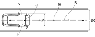
- the magnetic sensor array 21 (FIG. 4) includes 15 magnetic sensors Cn (n is an integer of 1 to 15) arranged in a straight line, and a detection processing circuit 212 incorporating a CPU or the like (not shown). ..
- 15 magnetic sensors Cn constituting the magnetic sensor array 21 are arranged at intervals of 10 cm along the longitudinal direction.
- the 15 magnetic sensors Cn are arranged along the vehicle width direction.
- the magnetic sensor C1 is located on the left side of the vehicle 5 (driver's seat side in the left steering wheel vehicle), and the magnetic sensor C15 is located on the right side of the vehicle 5 (passenger seat side) (see FIG. 10). .).
- the magnetic sensor Cn is a sensor that detects magnetism by utilizing a known MI effect (Magnet Impedance Effect) in which the impedance of a magnetic sensor such as an amorphous wire changes sensitively in response to an external magnetic field.
- the magnetic sensor Cn has magnetic sensitivity in the longitudinal direction of the amorphous wire.
- a magnetic sensory body such as an amorphous wire is arranged along two orthogonal axial directions. According to the magnetic sensor Cn, it is possible to detect magnetism acting in two orthogonal axial directions.
- a magnetic sensor Cn is incorporated so that magnetic components in the traveling direction and the vehicle width direction can be detected when the sensor unit 2 is attached to the vehicle 5.
- the magnetic sensor Cn is a highly sensitive sensor having a magnetic flux density measurement range of ⁇ 0.6 mT and a magnetic flux resolution within the measurement range of 0.02 ⁇ T.
- the frequency of magnetic measurement by each magnetic sensor Cn of the sensor unit 2 is set to 3 kHz so as to support high-speed traveling of the vehicle.
- Table 2 shows a part of the specifications of the magnetic sensor Cn.
- the magnetic marker 30 can act on magnetism having a magnetic flux density of 8 ⁇ T or more in a range of 100 to 250 mm assumed as the mounting height of the magnetic sensor Cn. If the magnetic marker 30 acts on magnetism with a magnetic flux density of 8 ⁇ T or more, it can be detected with high certainty using a magnetic sensor Cn having a magnetic flux resolution of 0.02 ⁇ T.
- the detection processing circuit 212 (FIG. 4) of the magnetic sensor array 21 is an arithmetic circuit that executes marker detection processing and the like for detecting the magnetic marker 30 (FIG. 1).
- the detection processing circuit 212 is configured by using a CPU (central processing unit) that executes various operations, and memory elements such as a ROM (read only memory) and a RAM (random access memory).
- the detection processing circuit 212 acquires the sensor signal output by each magnetic sensor Cn at a frequency of 3 kHz and executes the marker detection process.
- the detection processing circuit 212 inputs the detection result of the marker detection processing to the positioning unit 12.
- the amount of lateral displacement of the target point of the vehicle 5 with respect to the magnetic marker 30 is measured.
- the IMU 22 (Fig. 4) is an inertial navigation unit that estimates the relative position of the vehicle 5 by inertial navigation.
- the IMU 22 includes a 2-axis magnetic sensor 221 which is an electronic compass for measuring orientation, a 2-axis acceleration sensor 222 for measuring acceleration, and a 2-axis gyro sensor 223 for measuring angular velocity around the yaw axis.
- the yaw axis is an axis in the vertical direction.
- the IMU 22 calculates the displacement amount by the second-order integration of the measured acceleration, and calculates the direction of the vehicle 5 by integrating the measured angular velocity.
- the displacement amount and direction calculated by the IMU 22 are input to the positioning unit 12.
- the tag reader 13 (FIG. 4) is a communication unit that wirelessly communicates with the RFID tag 35 attached to the end surface of the magnetic marker 30.
- the tag reader 13 wirelessly transmits the electric power required for the operation of the RFID tag 35, and receives the position data transmitted by the RFID tag 35.
- This position data which is an example of the marker position information, is data representing the laying position (absolute position) of the corresponding magnetic marker 30.
- Positioning unit The positioning unit 12 (FIG. 4) controls the sensor unit 2 and the tag reader 13, and is the position of the target point (appropriately referred to as the target point of the vehicle) set for the vehicle 5. It is a unit that identifies the position in real time.
- the positioning unit 12 inputs the position of the own vehicle to the travel control unit 11 that controls the travel of the vehicle 5.
- the positioning unit 12 includes an electronic board (not shown) on which memory elements such as ROM and RAM are mounted, in addition to a CPU that executes various calculations.
- the method by which the positioning unit 12 identifies the position of the own vehicle differs between when the vehicle 5 reaches the magnetic marker 30 and when the vehicle 5 is located between the adjacent magnetic markers 30.
- the positioning unit 12 specifies the position of the own vehicle based on the position data (marker position information) received from the RFID tag 35.
- the position of the own vehicle is specified by using the relative position of the vehicle 5 estimated by inertial navigation.
- the travel control unit 11 (FIG. 4) is a unit that controls the vehicle 5 in order to realize automatic driving to a destination set by the driver, for example.
- the travel control unit 11 includes a route data generation unit 111 that generates route data representing a target route, a vehicle control unit 112 that controls the vehicle 5, a target point selection processing unit 113 that selects a target point to be set for the vehicle 5.
- the target point update processing unit 114 which updates the target point to be controlled, is included.
- a map database (map DB) 110 that stores detailed three-dimensional map data (3D map data) is connected to the travel control unit 11. Further, a steering steering unit 151, an engine throttle 152, a brake actuator 153, and the like are connected to the travel control unit 11 in a controllable manner.
- the travel control unit 11 includes an electronic board on which a CPU (not shown), a memory device such as a ROM or RAM, and an I / O chip for input / output with the outside are mounted.
- the travel control unit 11 realizes the functions of the above-mentioned units 111 to 114 by, for example, the CPU executing a program read from the ROM. Further, in the storage area of the ROM, data of vehicle specifications such as a vehicle width which is a dimension of the width of the vehicle 5 and a wheelbase which is a distance between the front wheel axle and the rear wheel axle are stored.
- the marker detection process is a process executed by the magnetic sensor array 21. As described above, the magnetic sensor array 21 executes the marker detection process at a frequency of 3 kHz using the magnetic sensor Cn.
- the magnetic sensor Cn can measure the magnetic components in the traveling direction and the vehicle width direction of the vehicle 5. For example, when the magnetic sensor Cn moves in the traveling direction and passes directly above the magnetic marker 30, the magnetic measurement values in the traveling direction are positive and negative inverted before and after the magnetic marker 30 as shown in FIG. It changes in time so as to intersect zero at a position directly above 30. While the vehicle 5 is traveling, the sensor unit 2 (magnetic sensor array 21) is directly above the magnetic marker 30 when a zero cross Zc in which the positive and negative directions of the magnetism in the traveling direction detected by any of the magnetic sensors Cn is reversed occurs. It can be judged that it is located in. The detection processing circuit 212 determines that the magnetic marker 30 has been detected when the sensor unit 2 is located directly above the magnetic marker 30 and a zero cross of the magnetic measurement values in the traveling direction occurs.
- the magnetic sensor moves along a virtual line in the vehicle width direction passing directly above the magnetic marker 30.
- the magnetic measurement values in the vehicle width direction are reversed in positive and negative directions on both sides of the magnetic marker 30, and change so as to intersect zeros at a position directly above the magnetic marker 30. Therefore, in the magnetic sensor array 21 in which 15 magnetic sensors Cn are arranged in the vehicle width direction, the positive and negative of the magnetism in the vehicle width direction detected by the magnetic sensor Cn differs depending on which side is located via the magnetic marker 30. Come (Fig. 6).
- a zero cross Zc in which the positive and negative of the magnetism in the vehicle width direction is reversed appears corresponding to the magnetic marker 30.
- the position of the zero cross Zc in the distribution in the figure represents the position of the magnetic marker 30 in the vehicle width direction.
- the position of the magnetic marker 30 in the vehicle width direction is, for example, an intermediate position between two magnetic sensors Cn adjacent to each other with the zero cross Zc in between, or a position where the magnetic measurement value in the vehicle width direction is zero and the magnetic sensors Cn on both outer sides. It can be specified as a position directly below the magnetic sensor Cn whose positive and negative are reversed.
- the example in the figure is an example in which the vehicle 5 is to the left in the lane.
- the positive / negative of the lateral displacement amount is positive when the target point of the vehicle is shifted to the left with respect to the magnetic marker 30, and negative when the target point of the vehicle is shifted to the right.
- the driver can set the destination by using, for example, an in-vehicle monitor such as a touch panel or a voice input system.
- the travel control unit 11 acquires the destination input by the driver (S101)
- the travel control unit 11 refers to the 3D map data stored in the map DB 110 and executes a route calculation for generating route data (S102).
- the route data is data representing the target route 1R to pass the target point of the vehicle 5 at the time of automatic driving control.
- the route data is data of a series of points (absolute positions) at the center of the lane 300.
- the magnetic markers 30 are arranged along the center of the lane 300. Therefore, the target route 1R represented by the route data coincides with the laying line of the magnetic marker 30.
- the vehicle 5 is controlled so that the target point of the vehicle 5 passes through the target route 1R (predetermined route).
- the target point of the vehicle 5 is updated at any time during the execution of the automatic driving control.
- the vehicle position in the following description means the absolute position of the target point being set.
- the positioning unit 12 controls the sensor unit 2 to repeatedly execute the above marker detection process (S201).
- the positioning unit 12 acquires the amount of lateral displacement of the target point with respect to the magnetic marker 30 and also acquires the marker position information (position data) of the RFID tag 35 (S223). ).
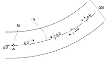
- the positioning unit 12 specifies a position offset by the amount of lateral displacement with reference to the laying position of the magnetic marker 30 represented by the position data as the own vehicle position (exemplified by the ⁇ mark in FIG. 8) (S204).
- the above-mentioned lateral displacement amount is the lateral displacement amount of the target point of the vehicle 5 with respect to the magnetic marker 30.
- the own vehicle position is the absolute position of the target point of the vehicle 5.
- the positioning unit 12 has the nearest own vehicle position specified at the time of detecting the magnetic markers 30.
- the relative position of the vehicle 5 with respect to (the position marked with ⁇ in FIG. 8) is estimated.
- the positioning unit 12 estimates the relative position by integrating the displacement amounts similarly taken in along the direction of the vehicle 5 taken in from the IMU 22.
- the positioning unit 12 has a cross mark obtained by adding the relative positions to the nearest own vehicle position (position marked with ⁇ in FIG. 8) specified at the time of detection of the magnetic marker 30.
- the position of is specified as the position of the own vehicle.
- the arrow in the figure is an example of a vector representing this relative position.
- the position of the own vehicle marked with ⁇ in the figure is the absolute position of the target point of the vehicle 5.
- the own vehicle position marked with x which is the sum of the relative positions with respect to the own vehicle position marked with ⁇ in the figure, is also the absolute position of the target point of the vehicle 5.
- the positioning unit 12 inputs the specified position of the own vehicle (position marked with ⁇ or ⁇ in FIG. 8) to the traveling control unit 11.
- the travel control unit 11 When the travel control unit 11 acquires the position of the own vehicle, it specifies the position of the own vehicle in the target route 1R. Then, the travel control unit 11 specifies the route shape in front of the vehicle 5 (S103).
- the travel control unit 11 specifies, for example, the curvature of the curve in front as a route specification which is a shape specification of the route in front of the vehicle 5.
- the route shape in front means the route shape in front of the vehicle 5 and several meters ahead.
- the route shape may be a route shape of several tens of meters ahead or a point reached by the vehicle 5 (zero m ahead) instead of several meters ahead. For example, when the route shape is specified at a point in front of the user and it is estimated that the route shape has been reached, the route shape may be specified.
- the travel control unit 11 selects a new target point by using the route specification and the vehicle specification stored in the ROM (S104, target point selection process).
- target point selection process for example, a position that reflects the route specifications such as the curvature of the curve and the vehicle specifications such as the vehicle width and the wheelbase is selected as a new target point. It is also possible to select a new target point in consideration of only one of the route specifications and the vehicle specifications. The details of the target point selection process will be described later.
- the travel control unit 11 updates the target point to be controlled by the target point newly selected in step S104 (S105, target point update process). Then, the travel control unit 11 calculates the deviation ⁇ D from the target route 1R for the updated new target point as shown in FIG. 9 (S106). Then, the traveling control unit 11 realizes automatic driving by executing vehicle control such as steering control and throttle control so that the deviation ⁇ D approaches zero (S107).
- the target route 1R represented by the route data of this example indicates the central position of the lane 300 forming the traveling route, that is, the position on the laying line of the magnetic marker 30.
- the vehicle 5 is controlled so as to travel along the center of the lane 300 as shown in FIG.
- the vehicle is controlled so as to travel to the right side in the lane 300 as shown in FIG.
- Target point selection process The target point selection process in step S104 in FIG. 7 is a process for selecting the target point of the vehicle 5.
- any position on the straight line in which 15 magnetic sensors C1 to C15 (Cn) are arranged is selected as the target point.
- the target point may be an intermediate position between adjacent magnetic sensors, such as C9.5.
- the position of the target point is expressed as the position of the magnetic sensor C8, the position of the magnetic sensor C2, and the like.
- the correction coefficients (FIGS. 12 and 13) applied to the target point selection process are defined.
- the correction coefficient D1 in FIG. 12 is a correction coefficient according to the curvature of the curve (an example of the route specification).
- the correction coefficient D2 in FIG. 13 is a correction coefficient according to the wheelbase (an example of vehicle specifications). As shown in FIGS. 12 and 13, the correction coefficients D1 and D2 become larger as the vehicle width W is larger. This is because the larger the vehicle width W, the greater the need to correct the target point.
- a new target point is selected by the calculation of the following mathematical formula 1.
- the target point for initial setting in Equation 1 is, for example, a target point suitable for a straight road, and for example, the position of the magnetic sensor C8 corresponding to the center of the vehicle 5 is set.
- the value of (target point for the initial setting) in Equation 1 is 8.
- the position of the magnetic sensor C3 is selected as the new target point.
- the " ⁇ " that switches whether to add or subtract the correction amount (D1 x D2) to the default target point is determined by whether it is a left curve or a right curve.
- a left curve it is necessary to move the vehicle 5 to the right in the lane in consideration of the inner ring difference. Therefore, in the case of a left curve, it is advisable to subtract the correction amount from the default target point so that the target point on the left side can be selected.
- the above formula 1 becomes (target point for initial setting)-(D1 ⁇ D2).
- the above formula 1 becomes (target point for initial setting) + (D1 ⁇ D2).
- an appropriate target point can be calculated depending on whether the route ahead (several meters ahead) goes straight or curves. For example, when the route ahead is a straight line, the correction coefficient D1 becomes almost zero because the curvature is almost zero. Therefore, when the route ahead is a straight line, the correction amount becomes almost zero regardless of the value of the correction coefficient D2, and the target point located near the default target point is selected. On the other hand, when the route ahead is a curve, the correction coefficient D1 becomes a large value and the correction amount becomes a large amount. As a result, a target point located away from the default target point is selected.
- the target point is not corrected when the front route is a straight line, and the degree of correction of the target point becomes stronger when the curvature of the front curve is large. It is a process.
- the degree of correction also differs depending on the vehicle width W. The larger the vehicle width W, the larger the correction coefficients D1 and D2 (see FIGS. 12 and 13), so that the degree of correction becomes stronger.
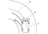
- FIG. 14 shows the inner ring difference that occurs when passing through a tight left curve with the target point set at the position of the magnetic sensor C8. If the vehicle travels on a tight left curve with the target point at the position of the magnetic sensor C8 suitable for a straight road, the left rear wheel is too close to the inside due to the difference between the inner wheels, and the space S inside the curve becomes insufficient. On the other hand, if the target point is set at the position of the magnetic sensor C2 on the left side as shown in FIG. 15, the vehicle 5 can travel in a large turn on the right side in the lane of the left curve. In this case, the space S inside the curve can be sufficiently secured without the left rear wheel being too close to the inside.
- the target point selection process in the case of a straight road, for example, near the position of the magnetic sensor C8, which is the default target point, is selected as the target point.
- a target point to the left of the position of the magnetic sensor C8 is selected by correction.
- the position of the magnetic sensor C8 is first selected as the target point in the straight section.
- a position on the left side such as the magnetic sensor C2 is selected as the target point. If the position of the central magnetic sensor C8 is selected as the target point in the straight section, the position of the vehicle 5 will not be biased in the lane. If a target point on the left side such as the magnetic sensor C2 is selected in the curve section, the left rear wheel on the inside of the curve will not be too close to the inside.
- the locus RG of the left rear wheel of the vehicle 5 includes a portion corresponding to a straight section of the locus R8 of the left rear wheel when the target point is the position of the magnetic sensor C8, and the target point is the magnetic sensor C2.
- a good locus is obtained by combining the portion of the locus R2 of the left rear wheel corresponding to the curve section at the position of.
- the longer the wheelbase the larger the correction coefficient D2 (FIG. 13).
- the degree of correction of the target point can be made stronger for a large vehicle having a long wheelbase than for a small vehicle.
- a large vehicle having a larger inner ring difference than a small vehicle can make a larger turning route when passing through a tight curve, and the trajectory of the rear wheels inside the curve can be improved.
- the automatic driving system 1 of this example is a system for driving the vehicle 5 by automatic steering so that the target point of the vehicle 5 passes through the target route 1R.
- the automatic operation system 1 has one of the technical features in that a target point to be controlled is selected and updated as needed.
- the route actually traveled by the vehicle 5 can be adjusted by updating the target point to be controlled. In this automatic driving system 1, it is less necessary to change the control specifications and the target route when adjusting the traveling route of the actual vehicle 5.
- the automatic driving system 1 can adjust the actual travel route of the vehicle 5 without changing the control specifications and the target route, and is highly versatile and applicable to various vehicle types and routes.
- the curvature of the curve is illustrated as the route specification. It is also good to include the lane width and lane type in the route specifications. This is because the narrower the lane width, the more accurately it is necessary to control the position of the vehicle in the lane.
- the type of lane includes a highway or a general road, an outer lane or an inner lane with two lanes on each side, and the like.
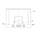
- the setting screen 50 (FIG. 17) on the in-vehicle monitor on which the driver can set the preference of the vehicle position in the lane.
- the vehicle position can be adjusted by using the right-pointing triangle mark 50R and the left-pointing triangle mark 50L, and the desired vehicle position can be set according to the operation of the enter button 52. It is preferable to correct the position of the target point according to the position of the desired touch vehicle set by using the setting screen 50.
- the vehicle-mounted monitor in this configuration is an example of an operation unit operated by the driver to adjust the position in the vehicle width direction occupied by the vehicle in the track.
- the travel control unit 11 as the target point selection processing unit may adjust the target point to the left (rightward) when, for example, a leftward (rightward) position is selected by the driver's operation with respect to the operation unit.
- this adjustment for example, an adjustment that shifts the target point selected by the above-mentioned target point selection process by a predetermined amount, an adjustment that shifts the initial setting target point in the above formula 1 by a predetermined amount, or the like can be adopted.
- the travel control unit can finely select the target point by using the learning result of the driver's preference for each type of road.
- the target point may be two-dimensionally selected in a horizontal plane parallel to the road surface.
- the target point may be selected regardless of whether it is inside or outside the vehicle.
- the target point 1S can be selected outside the vehicle 5.
- the parked vehicle 59 can be avoided by the normal automatic driving control without switching to the special control for avoiding the parked vehicle 59. For example, if a target point outside the vehicle 5 is selected by the target point selection process, it is possible to change lanes in order to overtake the preceding vehicle traveling in the lane related to the target route 1R.
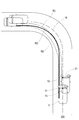
- the target point 1S to be controlled by selecting the target point 1S to be controlled, it is possible to control to avoid obstacles on the target route 1R, control to execute a lane change, and the like. At that time, if the target point 1S located outside the vehicle 5 is selected, lateral control with a lateral displacement amount that exceeds the vehicle width or half of the vehicle width becomes possible. For example, as shown in FIG. 19, when the lane change is executed in order to avoid an obstacle such as the preceding vehicle 591 on the route, the target point 1S to be controlled is positioned so as to overlap the preceding vehicle 591, or the vehicle 5 is positioned. It may be located in another lane 300 adjacent to the lane 300. By selecting the target point 1S to be controlled in this way, lateral control of the vehicle 5 can be realized.
- a correction coefficient D3 whose value increases according to the steering angle of the steering wheel may be adopted.
- a new target point can be selected by the calculation of the following mathematical formula 2.
Landscapes
- Engineering & Computer Science (AREA)
- Transportation (AREA)
- Mechanical Engineering (AREA)
- Automation & Control Theory (AREA)
- Radar, Positioning & Navigation (AREA)
- Remote Sensing (AREA)
- Physics & Mathematics (AREA)
- Combustion & Propulsion (AREA)
- Chemical & Material Sciences (AREA)
- General Physics & Mathematics (AREA)
- Human Computer Interaction (AREA)
- Electromagnetism (AREA)
- Aviation & Aerospace Engineering (AREA)
- Steering Control In Accordance With Driving Conditions (AREA)
- Control Of Driving Devices And Active Controlling Of Vehicle (AREA)
- Control Of Position, Course, Altitude, Or Attitude Of Moving Bodies (AREA)
Abstract
Description
前記車両に対して設定された対象点が所定のルートを通過するように前記車両を制御する走行制御処理と、
前記対象点に設定される新たな対象点を選定する対象点選定処理と、
前記走行制御処理の制御対象である前記対象点を、前記対象点選定処理によって選定された前記新たな対象点に更新する対象点更新処理と、を実行する車両用の制御方法にある。
前記車両に対して設定された対象点が所定のルートを通過するように前記車両を制御する車両制御部と、
前記対象点に設定される新たな対象点を選定する対象点選定処理部と、
前記車両制御部の制御対象である前記対象点を、前記対象点選定処理部によって選定された前記新たな対象点に更新する対象点更新処理部と、を含む車両用の制御システムにある。
(実施例1)
本例は、予め設定された目標ルート(所定のルートの一例)に沿って車両5を走行させるための制御方法及び制御システムに関する例である。この内容について、図1~図19を用いて説明する。
(1)磁気マーカ
磁気マーカ30は、図1及び図2のごとく、道路の路面300Sに敷設される道路用マーカである。磁気マーカ30は、左右のレーンマークで区分された車線(図8中の符号300、走路)の中央に沿って例えば10m間隔で配置されている。

センサユニット2は、図1及び図4のごとく、磁気検出部である磁気センサアレイ21と、慣性航法に用いられるIMU(Inertial Measurement Unit)22と、が一体化された棒状のユニットである。センサユニット2は、車幅方向に沿う状態で、路面300Sに対面して取り付けられる。例えば車両5のフロントバンパーの内側等に取り付けられたセンサユニット2は、路面300Sを基準とした取付け高さが200mmとなっている。

タグリーダ13(図4)は、磁気マーカ30の端面に貼り付けられたRFIDタグ35と無線で通信する通信ユニットである。タグリーダ13は、RFIDタグ35の動作に必要な電力を無線で送電し、RFIDタグ35が送信する位置データを受信する。マーカ位置情報の一例であるこの位置データは、対応する磁気マーカ30の敷設位置(絶対位置)を表すデータである。
測位ユニット12(図4)は、センサユニット2やタグリーダ13を制御し、車両5に対して設定された対象点(適宜、車両の対象点という。)の位置である自車位置をリアルタイムで特定するユニットである。測位ユニット12は、車両5の走行を制御する走行制御ユニット11に自車位置を入力する。
走行制御ユニット11(図4)は、例えばドライバーが設定した目的地までの自動運転を実現するために車両5を制御するユニットである。走行制御ユニット11は、目標ルートを表すルートデータを生成するルートデータ生成部111、車両5を制御する車両制御部112、車両5に対して設定する対象点を選定する対象点選定処理部113、制御対象の対象点を更新する対象点更新処理部114、を含んでいる。
(A)マーカ検出処理
マーカ検出処理は、磁気センサアレイ21が実行する処理である。磁気センサアレイ21は、上記の通り、磁気センサCnを用いて3kHzの周波数でマーカ検出処理を実行する。
次に、図7等を参照しながら自動運転システム1の全体動作について説明する。
自動運転システム1では、例えばタッチパネル等の車載モニターや音声入力システムなどを利用して、ドライバーが目的地を設定可能である。走行制御ユニット11は、ドライバーが入力した目的地を取得すると(S101)、地図DB110に格納された3Dマップデータを参照し、ルートデータを生成する経路演算を実行する(S102)。
図7中のステップS104の対象点選定処理は、車両5の対象点を選定するための処理である。本例の対象点選定処理では、15個の磁気センサC1~C15(Cn)が配列された直線上のいずれかの位置が対象点として選定される。対象点は、例えばC9.5など、隣り合う磁気センサ間の中間的な位置であっても良い。以下の説明では、対象点の位置を、磁気センサC8の位置や磁気センサC2の位置などと表現する。


1R 目標ルート(所定のルート)
1S 対象点
11 走行制御ユニット
12 測位ユニット
13 タグリーダ
110 地図データベース(地図DB)
111 ルートデータ生成部
112 車両制御部
113 対象点選定処理部
114 対象点更新処理部
2 センサユニット
21 磁気センサアレイ
212 検出処理回路
22 IMU
30 磁気マーカ
35 RFIDタグ
5 車両
Claims (13)
- 自動操舵により車両を走行させるための制御方法であって、
前記車両に対して設定された対象点が所定のルートを通過するように前記車両を制御する走行制御処理と、
前記対象点に設定される新たな対象点を選定する対象点選定処理と、
前記走行制御処理の制御対象である前記対象点を、前記対象点選定処理によって選定された前記新たな対象点に更新する対象点更新処理と、を実行する車両用の制御方法。 - 請求項1において、前記対象点選定処理は、前記所定のルートの形状的な仕様であるルート仕様、及び前記車両の仕様である車両仕様のうちの少なくともいずれか一方が反映された位置を、前記新たな対象点として選定する処理である車両用の制御方法。
- 請求項1または2において、前記対象点選定処理は、前記対象点の初期設定の位置を補正することにより、前記新たな対象点を選定する処理であり、
当該対象点選定処理による前記対象点の初期設定の位置の補正量は、前記所定のルートの形状的な仕様であるルート仕様を表す補正係数D1と、前記車両の仕様である車両仕様を表す補正係数D2と、を掛け合わせた量である車両用の制御方法。 - 請求項3において、前記補正係数D1は、前記所定のルートの曲率に応じた補正係数であり、前記補正係数D2は、前記車両のホイールベースに比例する補正係数である車両用の制御方法。
- 請求項3または4において、前記補正係数D1は、前記所定のルートが直線路であるときゼロとなる係数である車両用の制御方法。
- 請求項3~5のいずれか1項において、前記補正係数D1は、車線幅や車線の種別に応じて変動する係数である車両用の制御方法。
- 請求項3~6のいずれか1項において、前記補正係数D2は、車幅に応じて変動する係数である車両用の制御方法。
- 請求項1~7のいずれか1項において、前記対象点選定処理は、前記所定のルート上の障害物を回避するため、あるいは走行中の車線を変更するための前記新たな対象点を選定可能である車両用の制御方法。
- 請求項8において、前記対象点選定処理は、前記車両の外側の位置を前記新たな対象点として選定可能である車両用の制御方法。
- 請求項1~9のいずれか1項において、前記対象点選定処理は、運転者による前記車両の運転中に当該運転者が好む前記車両の位置を学習し、該車両の位置の学習結果を利用して前記新たな対象点を選定する車両用の制御方法。
- 自動操舵により車両を走行させるための制御システムであって、
前記車両に対して設定された対象点が所定のルートを通過するように前記車両を制御する車両制御部と、
前記対象点に設定される新たな対象点を選定する対象点選定処理部と、
前記車両制御部の制御対象である前記対象点を、前記対象点選定処理部によって選定された前記新たな対象点に更新する対象点更新処理部と、を含む車両用の制御システム。 - 請求項11において、前記対象点選定処理部は、前記車両が走行する走路の形状的な仕様であるルート仕様、及び前記車両の仕様である車両仕様のうちの少なくともいずれか一方が反映された位置を、前記新たな対象点として選定する車両用の制御システム。
- 請求項11または12において、走路における前記車両の車幅方向の位置を調整するために運転者が操作する操作部を含み、前記対象点選定処理部は、該操作部に対する運転者の操作に応じて前記新たな対象点の位置を補正する車両用の制御システム。
Priority Applications (4)
| Application Number | Priority Date | Filing Date | Title |
|---|---|---|---|
| JP2021526882A JP7406130B2 (ja) | 2019-06-21 | 2020-06-18 | 車両用の制御方法及び制御システム |
| EP20826872.2A EP3989199A4 (en) | 2019-06-21 | 2020-06-18 | Control method and control system for vehicle |
| CN202080043672.4A CN113993762B (zh) | 2019-06-21 | 2020-06-18 | 车辆用的控制方法 |
| US17/619,592 US20220340202A1 (en) | 2019-06-21 | 2020-06-18 | Vehicular control method and control system |
Applications Claiming Priority (2)
| Application Number | Priority Date | Filing Date | Title |
|---|---|---|---|
| JP2019115911 | 2019-06-21 | ||
| JP2019-115911 | 2019-06-21 |
Publications (1)
| Publication Number | Publication Date |
|---|---|
| WO2020256070A1 true WO2020256070A1 (ja) | 2020-12-24 |
Family
ID=74040852
Family Applications (1)
| Application Number | Title | Priority Date | Filing Date |
|---|---|---|---|
| PCT/JP2020/024003 Ceased WO2020256070A1 (ja) | 2019-06-21 | 2020-06-18 | 車両用の制御方法及び制御システム |
Country Status (5)
| Country | Link |
|---|---|
| US (1) | US20220340202A1 (ja) |
| EP (1) | EP3989199A4 (ja) |
| JP (1) | JP7406130B2 (ja) |
| CN (1) | CN113993762B (ja) |
| WO (1) | WO2020256070A1 (ja) |
Cited By (2)
| Publication number | Priority date | Publication date | Assignee | Title |
|---|---|---|---|---|
| JP2022030406A (ja) * | 2020-08-07 | 2022-02-18 | 株式会社ジェイテクト | 走行支援装置及び磁気マーカの敷設方法 |
| JP2025083722A (ja) * | 2023-11-21 | 2025-06-02 | 財団法人車輌研究測試中心 | 仮想軌道における車両の移動決定システム及びその方法 |
Families Citing this family (3)
| Publication number | Priority date | Publication date | Assignee | Title |
|---|---|---|---|---|
| US11604476B1 (en) * | 2018-10-05 | 2023-03-14 | Glydways Inc. | Road-based vehicle guidance system |
| JP7472869B2 (ja) * | 2021-07-26 | 2024-04-23 | トヨタ自動車株式会社 | 車両制御システム、車両制御方法、及び車両制御プログラム |
| US20240217521A1 (en) * | 2022-12-28 | 2024-07-04 | Automotive Research & Testing Center | Virtual track detection system and method |
Citations (6)
| Publication number | Priority date | Publication date | Assignee | Title |
|---|---|---|---|---|
| JPH09282033A (ja) * | 1996-04-12 | 1997-10-31 | Toyota Motor Corp | 車両の自動操舵制御装置 |
| JP2001001922A (ja) * | 1999-06-18 | 2001-01-09 | Mazda Motor Corp | 車両の操舵装置 |
| JP2001264076A (ja) | 2000-03-21 | 2001-09-26 | Clarion Co Ltd | カーナビゲーション装置 |
| JP2017052412A (ja) * | 2015-09-09 | 2017-03-16 | 株式会社デンソー | 運転支援装置、及び運転支援方法 |
| WO2017159493A1 (ja) * | 2016-03-15 | 2017-09-21 | 本田技研工業株式会社 | 車両制御システム、車両制御方法、および車両制御プログラム |
| WO2017199751A1 (ja) * | 2016-05-16 | 2017-11-23 | 本田技研工業株式会社 | 車両制御システム、車両制御方法、および車両制御プログラム |
Family Cites Families (48)
| Publication number | Priority date | Publication date | Assignee | Title |
|---|---|---|---|---|
| US3628624A (en) * | 1967-04-26 | 1971-12-21 | Buero Patent Ag | Guidance system for self-propelled trackless carriages |
| US4401181A (en) * | 1981-03-12 | 1983-08-30 | Schwarz Alfred V | Road vehicle control system |
| JP2665738B2 (ja) * | 1986-07-11 | 1997-10-22 | 株式会社小松製作所 | 地点追従方式による無人移動機械の誘導方法 |
| FR2610427B1 (fr) * | 1987-02-04 | 1995-09-29 | Protee | Systeme et procede de controle de la marche d'un vehicule autonome |
| JP2579808B2 (ja) * | 1988-10-14 | 1997-02-12 | 株式会社椿本チエイン | 移動体の誘導方法及びその装置 |
| JP2652573B2 (ja) * | 1989-08-25 | 1997-09-10 | 博夫 庄司 | ゴルフカート走行誘導法 |
| US5191528A (en) * | 1990-06-28 | 1993-03-02 | Eaton-Kenway, Inc. | Update marker system for naviagtion of an automatic guided vehicle |
| JP3289565B2 (ja) * | 1995-08-23 | 2002-06-10 | トヨタ自動車株式会社 | 自動操舵システム |
| KR980010679A (ko) * | 1996-03-29 | 1998-04-30 | 헨리 D.G 웰레스 | 차량의 제어방법 및 그 장치 |
| JPH10320690A (ja) * | 1997-05-15 | 1998-12-04 | Honda Motor Co Ltd | 自動走行車両用道路 |
| JP2002063682A (ja) * | 2000-08-21 | 2002-02-28 | Nec Corp | 走行位置検出装置 |
| JP2002286456A (ja) * | 2001-03-27 | 2002-10-03 | Mitsubishi Electric Corp | 車両位置認識装置 |
| JP3945185B2 (ja) * | 2001-05-22 | 2007-07-18 | いすゞ自動車株式会社 | 自動操舵装置 |
| NL1019191C2 (nl) * | 2001-10-18 | 2003-04-23 | Frog Navigation Systems B V | Voertuig en werkwijze voor het besturen daarvan. |
| US20050021195A1 (en) * | 2003-07-21 | 2005-01-27 | Rapistan Systems Advertising Corp. | Dynamic object avoidance with automated guided vehicle |
| JP2005202478A (ja) * | 2004-01-13 | 2005-07-28 | Denso Corp | 車両用自動走行システム |
| JP2007233604A (ja) * | 2006-02-28 | 2007-09-13 | Toyota Motor Corp | 道路情報取得装置、及びこれを利用した車両用走行制御装置、並びに道路交通システム |
| CN101842759B (zh) * | 2007-10-31 | 2013-01-02 | 丰田自动车株式会社 | 输送用自走车及其停止控制方法 |
| US8392064B2 (en) * | 2008-05-27 | 2013-03-05 | The Board Of Trustees Of The Leland Stanford Junior University | Systems, methods and devices for adaptive steering control of automotive vehicles |
| JP5332952B2 (ja) * | 2009-06-26 | 2013-11-06 | トヨタ車体株式会社 | 無人搬送車の走行制御装置 |
| JP4901919B2 (ja) * | 2009-07-13 | 2012-03-21 | 株式会社東芝 | X線コンピュータ断層撮影装置及びx線検出装置製造方法 |
| US9168924B2 (en) * | 2012-03-26 | 2015-10-27 | GM Global Technology Operations LLC | System diagnosis in autonomous driving |
| DE102013212708B4 (de) * | 2013-06-28 | 2022-01-13 | Volkswagen Aktiengesellschaft | Verfahren und Vorrichtung zur Durchführung autonomer Fahrmanöver eines Fahrzeugs |
| US20150294566A1 (en) * | 2014-04-15 | 2015-10-15 | Tomorrow's Transportation Today | Trip planning and management methods for an intelligent transit system with electronic guided buses |
| US20150294430A1 (en) * | 2014-04-15 | 2015-10-15 | Tomorrow's Transportation Today | Dynamic dispatching and schedule management methods for an intelligent transit system with electronic guided buses |
| US9892296B2 (en) * | 2014-11-12 | 2018-02-13 | Joseph E. Kovarik | Method and system for autonomous vehicles |
| JP6559453B2 (ja) * | 2015-03-31 | 2019-08-14 | アイシン・エィ・ダブリュ株式会社 | 自動運転支援システム、自動運転支援方法及びコンピュータプログラム |
| CA2936369A1 (en) * | 2015-07-16 | 2017-01-16 | Iain Wilson | Robotic apparatus for plowing of snow from a predefined area |
| JP2017078909A (ja) * | 2015-10-19 | 2017-04-27 | 愛知製鋼株式会社 | 磁気マーカ及び磁気マーカ検出システム |
| JP6172237B2 (ja) * | 2015-10-23 | 2017-08-02 | 愛知製鋼株式会社 | 磁気マーカ検出方法及び磁気マーカ検出装置 |
| JP6947171B2 (ja) * | 2016-04-28 | 2021-10-13 | 愛知製鋼株式会社 | 運転支援システム |
| JP6916784B2 (ja) * | 2016-06-03 | 2021-08-11 | 愛知製鋼株式会社 | 位置捕捉方法及びシステム |
| RU2735720C1 (ru) * | 2016-10-07 | 2020-11-06 | Ниссан Мотор Ко., Лтд. | Способ оценки транспортного средства, способ корректировки маршрута движения, устройство оценки транспортного средства и устройство корректировки маршрута движения |
| JP6923306B2 (ja) * | 2016-11-09 | 2021-08-18 | 株式会社野村総合研究所 | 車両運転支援システム |
| JP6345225B1 (ja) * | 2016-12-21 | 2018-06-20 | 三菱電機株式会社 | 車両用操舵システムおよびレーンキープシステム |
| JP6614172B2 (ja) * | 2017-01-31 | 2019-12-04 | 京セラドキュメントソリューションズ株式会社 | 自走車両システム、自走車両、及び自走車両の走行制御方法 |
| SE540698C2 (en) * | 2017-02-07 | 2018-10-16 | Scania Cv Ab | Method and control unit for estimating bias of yaw rate sensor |
| KR20190014871A (ko) * | 2017-08-04 | 2019-02-13 | 삼성전자주식회사 | 차량의 후방에 위치한 응급 차량에 기초하여 상기 차량의 주행 경로를 변경하는 장치 및 방법 |
| US10571923B2 (en) * | 2017-09-20 | 2020-02-25 | Tata Consultancy Services Limited | System and method for steering control during autonomous vehicle driving |
| JP6599420B2 (ja) * | 2017-12-01 | 2019-10-30 | 本田技研工業株式会社 | 自動搬送車 |
| KR102122747B1 (ko) * | 2018-08-02 | 2020-06-16 | 주식회사 정석케미칼 | 자기장 발생 방법과 자기장을 이용한 차선 감지 방법, 이를 이용한 자동차 |
| US11604476B1 (en) * | 2018-10-05 | 2023-03-14 | Glydways Inc. | Road-based vehicle guidance system |
| KR102692121B1 (ko) * | 2018-12-07 | 2024-08-05 | 현대자동차 주식회사 | 무인운반차량 통제 시스템 및 그 방법 |
| JP7389359B2 (ja) * | 2018-12-28 | 2023-11-30 | 愛知製鋼株式会社 | 車両及び車両用の診断システム |
| JP7268498B2 (ja) * | 2019-06-24 | 2023-05-08 | 愛知製鋼株式会社 | 磁気マーカ及び磁気マーカの利用方法 |
| JP7433071B2 (ja) * | 2020-02-13 | 2024-02-19 | 三菱重工業株式会社 | センサ制御用無線タグ、移動体および点検システム |
| US20230250598A1 (en) * | 2020-06-26 | 2023-08-10 | Aichi Steel Corporation | Marker system and magnetic marker detection method |
| US12292293B2 (en) * | 2022-11-30 | 2025-05-06 | Automotive Research & Testing Center | Magnet-guiding switching system and magnet-guiding switching method |
-
2020
- 2020-06-18 CN CN202080043672.4A patent/CN113993762B/zh active Active
- 2020-06-18 EP EP20826872.2A patent/EP3989199A4/en active Pending
- 2020-06-18 JP JP2021526882A patent/JP7406130B2/ja active Active
- 2020-06-18 WO PCT/JP2020/024003 patent/WO2020256070A1/ja not_active Ceased
- 2020-06-18 US US17/619,592 patent/US20220340202A1/en not_active Abandoned
Patent Citations (6)
| Publication number | Priority date | Publication date | Assignee | Title |
|---|---|---|---|---|
| JPH09282033A (ja) * | 1996-04-12 | 1997-10-31 | Toyota Motor Corp | 車両の自動操舵制御装置 |
| JP2001001922A (ja) * | 1999-06-18 | 2001-01-09 | Mazda Motor Corp | 車両の操舵装置 |
| JP2001264076A (ja) | 2000-03-21 | 2001-09-26 | Clarion Co Ltd | カーナビゲーション装置 |
| JP2017052412A (ja) * | 2015-09-09 | 2017-03-16 | 株式会社デンソー | 運転支援装置、及び運転支援方法 |
| WO2017159493A1 (ja) * | 2016-03-15 | 2017-09-21 | 本田技研工業株式会社 | 車両制御システム、車両制御方法、および車両制御プログラム |
| WO2017199751A1 (ja) * | 2016-05-16 | 2017-11-23 | 本田技研工業株式会社 | 車両制御システム、車両制御方法、および車両制御プログラム |
Non-Patent Citations (1)
| Title |
|---|
| See also references of EP3989199A4 |
Cited By (3)
| Publication number | Priority date | Publication date | Assignee | Title |
|---|---|---|---|---|
| JP2022030406A (ja) * | 2020-08-07 | 2022-02-18 | 株式会社ジェイテクト | 走行支援装置及び磁気マーカの敷設方法 |
| JP7537170B2 (ja) | 2020-08-07 | 2024-08-21 | 株式会社ジェイテクト | 走行支援装置及び磁気マーカの敷設方法 |
| JP2025083722A (ja) * | 2023-11-21 | 2025-06-02 | 財団法人車輌研究測試中心 | 仮想軌道における車両の移動決定システム及びその方法 |
Also Published As
| Publication number | Publication date |
|---|---|
| EP3989199A1 (en) | 2022-04-27 |
| CN113993762B (zh) | 2025-01-03 |
| CN113993762A (zh) | 2022-01-28 |
| US20220340202A1 (en) | 2022-10-27 |
| JPWO2020256070A1 (ja) | 2020-12-24 |
| EP3989199A4 (en) | 2023-07-19 |
| JP7406130B2 (ja) | 2023-12-27 |
Similar Documents
| Publication | Publication Date | Title |
|---|---|---|
| JP7260856B2 (ja) | 車両の走行制御方法及び車両制御システム | |
| JP7406130B2 (ja) | 車両用の制御方法及び制御システム | |
| US11119499B2 (en) | Marker system | |
| JP6946695B2 (ja) | マーカシステム | |
| CN112204352B (zh) | 陀螺仪传感器的校正方法 | |
| JP6828314B2 (ja) | 車両用の学習システム及び学習方法 | |
| US11231721B2 (en) | Marker system and operation method | |
| US11505191B2 (en) | Vehicle traveling control device | |
| WO2019054183A1 (ja) | 位置捕捉システム及び位置捕捉方法 | |
| WO2024063078A1 (ja) | 3次元地図データの生成方法及び生成システム | |
| US20240393801A1 (en) | Control method and control system | |
| US20250390100A1 (en) | Control method and control system | |
| JP7381939B2 (ja) | 3次元構造推定方法及び3次元構造推定システム | |
| JP2024121590A (ja) | 位置推定システム |
Legal Events
| Date | Code | Title | Description |
|---|---|---|---|
| 121 | Ep: the epo has been informed by wipo that ep was designated in this application |
Ref document number: 20826872 Country of ref document: EP Kind code of ref document: A1 |
|
| DPE1 | Request for preliminary examination filed after expiration of 19th month from priority date (pct application filed from 20040101) | ||
| ENP | Entry into the national phase |
Ref document number: 2021526882 Country of ref document: JP Kind code of ref document: A |
|
| NENP | Non-entry into the national phase |
Ref country code: DE |
|
| WWE | Wipo information: entry into national phase |
Ref document number: 2020826872 Country of ref document: EP |
|
| WWG | Wipo information: grant in national office |
Ref document number: 202080043672.4 Country of ref document: CN |