WO2020256409A1 - Feuille de blindage de champ magnétique et son procédé de fabrication - Google Patents
Feuille de blindage de champ magnétique et son procédé de fabrication Download PDFInfo
- Publication number
- WO2020256409A1 WO2020256409A1 PCT/KR2020/007848 KR2020007848W WO2020256409A1 WO 2020256409 A1 WO2020256409 A1 WO 2020256409A1 KR 2020007848 W KR2020007848 W KR 2020007848W WO 2020256409 A1 WO2020256409 A1 WO 2020256409A1
- Authority
- WO
- WIPO (PCT)
- Prior art keywords
- sheet
- sheet body
- magnetic field
- area
- field shielding
- Prior art date
- Legal status (The legal status is an assumption and is not a legal conclusion. Google has not performed a legal analysis and makes no representation as to the accuracy of the status listed.)
- Ceased
Links
Images




Classifications
-
- H—ELECTRICITY
- H04—ELECTRIC COMMUNICATION TECHNIQUE
- H04B—TRANSMISSION
- H04B5/00—Near-field transmission systems, e.g. inductive or capacitive transmission systems
- H04B5/70—Near-field transmission systems, e.g. inductive or capacitive transmission systems specially adapted for specific purposes
- H04B5/79—Near-field transmission systems, e.g. inductive or capacitive transmission systems specially adapted for specific purposes for data transfer in combination with power transfer
-
- H—ELECTRICITY
- H02—GENERATION; CONVERSION OR DISTRIBUTION OF ELECTRIC POWER
- H02J—ELECTRIC POWER NETWORKS; CIRCUIT ARRANGEMENTS OR SYSTEMS FOR SUPPLYING OR DISTRIBUTING ELECTRIC POWER; SYSTEMS FOR STORING ELECTRIC ENERGY
- H02J50/00—Circuit arrangements or systems for wireless supply or distribution of electric power
- H02J50/70—Circuit arrangements or systems for wireless supply or distribution of electric power involving the reduction of electric, magnetic or electromagnetic leakage fields
-
- H—ELECTRICITY
- H01—ELECTRIC ELEMENTS
- H01F—MAGNETS; INDUCTANCES; TRANSFORMERS; SELECTION OF MATERIALS FOR THEIR MAGNETIC PROPERTIES
- H01F27/00—Details of transformers or inductances, in general
- H01F27/34—Special means for preventing or reducing unwanted electric or magnetic effects, e.g. no-load losses, reactive currents, harmonics, oscillations, leakage fields
- H01F27/36—Electric or magnetic shields or screens
-
- H—ELECTRICITY
- H01—ELECTRIC ELEMENTS
- H01F—MAGNETS; INDUCTANCES; TRANSFORMERS; SELECTION OF MATERIALS FOR THEIR MAGNETIC PROPERTIES
- H01F41/00—Apparatus or processes specially adapted for manufacturing or assembling magnets, inductances or transformers; Apparatus or processes specially adapted for manufacturing materials characterised by their magnetic properties
- H01F41/02—Apparatus or processes specially adapted for manufacturing or assembling magnets, inductances or transformers; Apparatus or processes specially adapted for manufacturing materials characterised by their magnetic properties for manufacturing cores, coils, or magnets
- H01F41/0206—Manufacturing of magnetic cores by mechanical means
-
- H—ELECTRICITY
- H01—ELECTRIC ELEMENTS
- H01Q—ANTENNAS, i.e. RADIO AERIALS
- H01Q1/00—Details of, or arrangements associated with, antennas
- H01Q1/52—Means for reducing coupling between antennas; Means for reducing coupling between an antenna and another structure
- H01Q1/526—Electromagnetic shields
-
- H—ELECTRICITY
- H02—GENERATION; CONVERSION OR DISTRIBUTION OF ELECTRIC POWER
- H02J—ELECTRIC POWER NETWORKS; CIRCUIT ARRANGEMENTS OR SYSTEMS FOR SUPPLYING OR DISTRIBUTING ELECTRIC POWER; SYSTEMS FOR STORING ELECTRIC ENERGY
- H02J50/00—Circuit arrangements or systems for wireless supply or distribution of electric power
- H02J50/20—Circuit arrangements or systems for wireless supply or distribution of electric power using microwaves or radio frequency waves
-
- H—ELECTRICITY
- H05—ELECTRIC TECHNIQUES NOT OTHERWISE PROVIDED FOR
- H05K—PRINTED CIRCUITS; CASINGS OR CONSTRUCTIONAL DETAILS OF ELECTRIC APPARATUS; MANUFACTURE OF ASSEMBLAGES OF ELECTRICAL COMPONENTS
- H05K9/00—Screening of apparatus or components against electric or magnetic fields
- H05K9/0073—Shielding materials
- H05K9/0075—Magnetic shielding materials
Definitions
- the present invention relates to a magnetic field shielding sheet and a method of manufacturing the same.
- NFC Near field communication
- wireless charging are essentially contactless transmission methods.
- Such a non-contact transmission method is implemented through an antenna that transmits or receives a magnetic field, and a magnetic field shielding sheet disposed on one side of the antenna so as to smoothly transmit or receive the magnetic field.
- a sheet made of a magnetic material such as an amorphous ribbon sheet, a ferrite sheet, or a polymer sheet is used as the magnetic field shielding sheet.
- the magnetic field shielding sheet is a sheet in a form separated into a plurality of pieces so as to greatly reduce loss due to eddy current or improve the flexibility of the sheet itself.
- the magnetic field shielding sheet may be separated into a plurality of pieces through a flake process.
- a flake process may be performed through a metal roller and a rubber roller in which a plurality of uneven or spherical balls are formed on the outer surface.
- the magnetic field shielding sheet when the magnetic field shielding sheet is passed through the metal roller and the rubber roller multiple times in a state in which the metal roller and the rubber roller are disposed oppositely, the magnetic field shielding sheet may be separated into a plurality of pieces.
- the entire area of the sheet is pressed through the pair of rollers. Accordingly, in the magnetic field shielding sheet produced through the flake process, the entire sheet is inevitably separated into a plurality of pieces.
- a magnetic field shielding sheet separated into a plurality of pieces through a conventional flake process may have uniform characteristics only when the flake process is performed a plurality of times.
- the present invention was devised in consideration of the above points, and a magnetic field shielding sheet capable of realizing a high permeability of 2000 or more while having a very thin thickness by forming a penetration part locally and cracks caused by it in only a part of the total area And there is an object to provide a method for manufacturing the same.
- another object of the present invention is to provide a method of manufacturing a magnetic field shielding sheet capable of selectively forming cracks in a region corresponding to an antenna among the total area even if a separate flake process is not performed.
- the present invention is a magnetic field shielding sheet for an antenna including a hollow portion having a predetermined area in a central portion and a pattern portion surrounding the hollow portion, comprising at least one of an amorphous alloy and a nanocrystalline alloy A sheet body formed of a ribbon sheet; A plurality of through portions formed in a region of the sheet body corresponding to the pattern portion; It provides a magnetic field shielding sheet including; and a plurality of cracks extending from the through portion.
- the through portion may be formed to be longer than the width.
- the plurality of through portions may be spaced apart from each other.
- the through portion may include a first portion formed in a region corresponding to the pattern portion and a second portion extending from the first portion to a region corresponding to the hollow portion of the antenna.
- the plurality of through portions may be connected to each other through the second portion.
- the plurality of through portions may be formed such that each second portion is connected to each other at a central point of the antenna hollow portion.
- the sheet body may be a multilayer sheet in which at least two or more layers of the plurality of ribbon sheets are stacked, and the sheet body may include a protective film attached to at least one of an upper surface and a lower surface through an adhesive layer. have.
- the magnetic field shielding sheet may have a total thickness of 55 ⁇ m to 85 ⁇ m.
- the plurality of through portions a first through portion formed in a direction perpendicular to the width direction or the length direction of the sheet body; A second through portion formed in a direction parallel to the width direction or the length direction of the sheet body; A third through part formed to be inclined at a predetermined angle with respect to the width direction or the length direction of the sheet body; And a fourth through part formed in an arc shape having a predetermined curvature. At least one or more of them may be included.
- the present invention is a magnetic field shielding sheet for an antenna comprising a hollow portion having a predetermined area in the central portion and a pattern portion surrounding the hollow portion, a ribbon sheet comprising at least one of an amorphous alloy and a nanocrystalline alloy is an adhesive layer
- a sheet body formed of a multilayered sheet stacked in two to three layers as a medium;
- a plurality of through portions formed through the sheet body in an arrangement area corresponding to the pattern portion and formed in a linear shape having a length longer than a width;
- a plurality of cracks extending from the through part toward the sheet body, wherein each of the plurality of through parts is formed in a linear shape having a width of 0.1 mm to 0.4 mm, and the plurality of through parts has a total number of 4 It provides a magnetic field shielding sheet formed so as not to be connected to each other and is 16.
- the present invention is a magnetic field shielding sheet for an antenna including a hollow portion having a predetermined area in the central portion and a pattern portion surrounding the hollow portion, formed of a ribbon sheet containing at least one of an amorphous alloy and a nanocrystalline alloy Seat body; A plurality of through portions formed in a corresponding region of the sheet body corresponding to the hollow portion of the antenna; It provides a magnetic field shielding sheet including; and a plurality of cracks extending from the through portion.
- the plurality of through portions may be arranged to surround the center point of the corresponding area, and a partial area including the center point of the corresponding area among the corresponding areas is formed through a plurality of cracks extending from the plurality of through portions. It may be formed separately into a plurality of pieces.
- the present invention is a wireless power reception antenna comprising a hollow portion having a predetermined area in the central portion and a pattern portion surrounding the hollow portion; And the above-described magnetic field shielding sheet disposed on one surface of the antenna for receiving wireless power.
- the above-described wireless power reception module can be applied to a portable terminal device.
- the present invention is a method of manufacturing a magnetic field shielding sheet for an antenna comprising a hollow portion having a predetermined area in the central portion and a pattern portion surrounding the hollow portion, comprising at least one of a heat-treated amorphous alloy and a nanocrystalline alloy
- a sheet body having a first area formed of a ribbon sheet First punching the sheet body to form a plurality of cracks extending from the through portion while forming a through portion having a predetermined width and length in an inner region of the sheet body; And secondary punching of the sheet body to form a shielding sheet having a second area that is relatively narrower than the first area while including the through part.
- the through part may be formed through the arrangement area in which the pattern part of the antenna is disposed.
- the through portion may be formed through the corresponding region corresponding to the hollow portion of the antenna.
- the step of first punching the sheet body may include a ring-shaped rim blade for forming an rim of the penetrating part and the rim blade so that the cut piece cut from the sheet body can be pressed and separated through the rim blade. It can be performed through a mold including a separating member formed in the inner region of the.
- the second punching of the sheet body may be a step of forming an outer border defining the second area on the sheet body so that the shielding sheet can be separated from the sheet body.
- the step of preparing the sheet body may include forming a multilayer sheet in which a plurality of ribbon sheets are stacked in multiple layers via a first adhesive layer; And attaching a protective film to a lower surface of the multilayer sheet via a second adhesive layer coated with an adhesive on both sides of the substrate, wherein the outer border is formed to penetrate the multilayer sheet and the second adhesive layer.
- cracks can be selectively formed in an area corresponding to an antenna or a partial area in which magnetic flux is concentrated among the total area. Through this, it is possible to easily manufacture a shielding sheet that satisfies the design conditions and requirements.
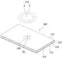
- FIG. 1 is a view showing a magnetic field shielding sheet according to an embodiment of the present invention
- FIG. 2 is a diagram conceptually illustrating a penetration portion that may be formed in an arrangement area corresponding to a pattern portion of an antenna in FIG. 1 and a crack caused by the penetration portion;
- FIG. 3 is a diagram conceptually illustrating different types of penetrations that may be formed in an arrangement area corresponding to the pattern portion of the antenna in FIG. 1 and cracks caused by the penetrations;
- FIG. 4 is a diagram conceptually showing various types of penetrations that can be formed in an arrangement area corresponding to the pattern portion of the antenna in FIG. 1 and cracks caused therefrom;
- FIG. 5 is a view showing a magnetic field shielding sheet according to another embodiment of the present invention.
- FIG. 6 is an enlarged view of a corresponding area corresponding to a hollow portion of an antenna in FIG. 5, and conceptually shows a through portion and a crack caused by the through portion;
- FIG. 7 is a diagram conceptually illustrating a through-hole of another type that may be formed in a corresponding region corresponding to a hollow portion of an antenna in FIG. 5 and a crack caused by the through-hole;
- FIG. 8 is a diagram conceptually showing various types of penetrations that may be formed in a corresponding region corresponding to a hollow part of an antenna in FIG. 5 and cracks caused therefrom;
- FIG. 9 is a cross-sectional view showing a detailed configuration of the magnetic field shielding sheet according to the present invention.
- FIG. 10 is a view showing a wireless power receiving module to which the magnetic field shielding sheet of FIG. 1 is applied as a wireless power receiving module according to an embodiment of the present invention
- FIG. 11 is a diagram showing a wireless power receiving module to which the magnetic field shielding sheet of FIG. 5 is applied as a wireless power receiving module according to another embodiment of the present invention
- FIG. 12 is a flow chart showing a method of manufacturing a magnetic field shielding sheet according to an embodiment of the present invention
- FIG. 13 is a view conceptually showing one form of a mold that can be used in the first punching step in the method of manufacturing a magnetic field shielding sheet according to an embodiment of the present invention
- FIG. 14A and 14B are plan views showing a mold applicable to FIG. 13, FIG. 14A is a plan view of an upper mold for primary punching, and FIG. 14B is a plan view of a lower mold for primary punching;
- FIG. 15A and 15B are plan views showing another form of a mold applicable to FIG. 13, FIG. 15A is a plan view of an upper mold for primary punching, and FIG. 15B is a plan view of a lower mold for primary punching,
- FIG. 16 is a plan view showing another form of an upper mold for primary punching that can be applied to FIG. 13;
- FIG. 17 is a plan view showing an embodiment of a mold that can be used in a second punching step in a method of manufacturing a magnetic field shielding sheet according to an embodiment of the present invention
- FIG. 18A is a plan view showing a multilayer sheet in a state in which primary punching is completed using the molds of FIGS. 14A and 14B
- FIG. 18B is a multilayer sheet showing a state in which secondary punching is completed using the mold of FIG. Shown top view
- FIG. 19A is a plan view showing a multilayer sheet in a state in which the first punching is completed using the molds of FIGS. 15A and 15B
- FIG. 19B is a multilayer sheet showing a state in which the second punching is completed using the mold of FIG. The floor plan shown, and,
- FIGS. 18B and 19B are cross-sectional views of a portion A-A in FIGS. 18B and 19B.
- Magnetic field shielding sheets 100 and 100 ′ include a sheet body 110, through portions 120 and 120 ′, and cracks 130 as shown in FIGS. 1 and 5.
- the sheet body 110 may be made of a material having magnetic properties so as to shield a magnetic field generated from the antennas 211 and 212.
- the antennas 211 and 212 may include a hollow portion E having a predetermined area at a central portion and a pattern portion P formed to surround the hollow portion E with a predetermined number of turns.
- the antennas 211 and 212 are antenna patterns in which a pattern portion P is patterned so that a hollow portion E having a predetermined area is formed on at least one surface of the circuit board 210 (see FIGS. 10 and 11 ).
- it may be a flat coil in which a conductive member having a predetermined wire diameter is wound a plurality of times so that a hollow portion E having a predetermined area is formed in the center portion to form the pattern portion P.
- the antennas 211 and 212 may be a wireless power transmission antenna 211 for transmitting or receiving wireless power, an MST antenna for magnetic payment, or an NFC antenna 212 for short-range communication.
- the antennas 211 and 212 may be configured as a combo type including two or more of the above-described wireless power transmission antenna 212, MST antenna, and NFC antenna 212.
- the sheet body 110 may be formed of a material including a metal component so that the crack 130 can be formed from the through portions 120 and 120 ′ together with the through portions 120 and 120 ′.
- the sheet body 110 may be a ribbon sheet 111a including at least one of an amorphous alloy and a nano-crystal alloy, as shown in FIG. 9.
- Such a sheet body 110 may be formed of a single-layered ribbon sheet 111a, but the sheet body 110 is a multilayer in which a plurality of ribbon sheets 111a are stacked in multiple layers via a first adhesive layer 111b. It could be a sheet.
- the multilayer sheet may be a multilayer sheet in which a plurality of ribbon sheets 111a are stacked in two to three layers.
- the total number of stacked multilayer sheets is not limited thereto, and the total number of stacked multilayer sheets may be appropriately changed according to design conditions.
- the sheet body 110 may be a hybrid sheet in which a ribbon sheet of an amorphous alloy and a ribbon sheet of a nano-crystal alloy are combined.
- a protective film 113 may be attached to at least one of the upper and lower surfaces of the sheet body 110 through the second adhesive layer 112.
- the sheet body 110 may maintain a plate shape through the protective film 113.
- the protective film 113 attached to at least one of the upper and lower surfaces of the sheet body 110 may be a removable release film. Through this, when the protective film 113 is removed from the sheet body 110, the second adhesive layer 112 disposed between the sheet body 110 and the protective film 113 may be exposed to the outside.
- the magnetic field shielding sheets 100 and 100 ′ according to an embodiment of the present invention may be attached to other components using the second adhesive layer 112.
- the magnetic field shielding sheets 100 and 100 ′ are provided with through portions 120 and 120 ′ formed in the inner region of the sheet body 110 as shown in FIGS. 2, 3, 6 and 7. ), and a plurality of cracks 130 extending from the through portions 120 and 120 ′.
- the through parts 120 and 120 ′ may be formed to penetrate the sheet body 110, and the plurality of cracks 130 extend from the through parts 120 and 120 ′ to the inside of the sheet body 110 It can be formed to be.
- the plurality of cracks 130 formed from the through portions 120 and 120 ′ may or may not be connected to each other. In addition, only some of the cracks 130 may be connected to each other.
- the through portions 120 and 120 ′ include all of the protective film 113 together with the sheet body 110 It may be formed to penetrate.
- the plurality of cracks 130 are caused from the through parts 120 and 120 ′ through an external force applied to the sheet body 110 while the through parts 120 and 120 ′ are formed in the sheet body 110 It may be formed.
- the magnetic field shielding sheets 100 and 100 ′ can increase the overall resistance through the through portions 120 and 120 ′ formed in the sheet body 110 and a plurality of cracks 130. The effect of eddy current can be reduced.
- the through portions 120 and 120 ′ formed in the sheet body 110 and the plurality of cracks 130 may function as an eddy current reduction means capable of reducing an eddy current.
- the through parts 120 and 120 ′ may be formed to have a predetermined width and length, and may be formed in an appropriate number of one or more.
- the through portions 120 and 120 ′ may be formed to have a length longer than a width.
- the total number of the plurality of cracks 130 may be relatively larger than the total number of the through portions 120 and 120 ′.
- the through portions 120 and 120 ′ may be formed in a linear shape having a length longer than a width.
- the through portions (120, 120') and a plurality of cracks (130) are formed locally for a partial area of the total area of the sheet body (110). Can be.
- the through portions 120 and 120 ′ and the plurality of cracks 130 are localized with respect to a partial area of the total area of the seat body 110 in consideration of an arrangement relationship with the antenna 211 for transmitting or receiving wireless power. Can be formed.
- the pattern part P of the antenna 211 is disposed among the total area of the sheet body 110 as shown in FIGS. 2 and 3 It may be formed in the arrangement area A1.
- the through portion 120 may further include a portion extending from the placement area A1 toward the hollow portion E of the antenna 211 in addition to the placement area A1.
- the through part 120 ′ and the plurality of cracks 130 are formed only in a partial area A2 in which magnetic flux is concentrated among the total area of the sheet body 110 as shown in FIGS. 6 and 7 It could be.
- the magnetic field shielding sheet (100, 100') is a partial area in which the pattern portion (P) of the antenna 211 is disposed or the hollow portion (E) of the antenna 211 Since the through portions 120 and 120' and a plurality of cracks 130 are partially formed only in a partial area corresponding to the sheet, the overall resistance of the sheet itself is increased to minimize the effect of the eddy current, while having a high permeability of 2000 or more in a very thin thickness I can.
- the magnetic field shielding sheets 100 and 100 ′ may have a high permeability of 2000 or more even at a very thin thickness of 55 ⁇ m to 85 ⁇ m.
- the magnetic field shielding sheets 100 and 100 ′ can increase the inductance of the antennas 211 and 212 while implementing a thinner thickness through a very thin thickness.
- the through part 120 and the through part A plurality of cracks 130 extending from 120 may be formed in an arrangement area A1 in which the pattern portion P of the antenna 211 is disposed among the entire area of the sheet body 110.
- the through part 120 is a hollow part of the antenna from the first part 121 formed in the arrangement area A1 where the pattern part P of the antenna is disposed and the first part 121 A second portion 122 extending to a position corresponding to (E) may be further included, and the plurality of cracks 130 may include portions formed from the second portion 122.
- the through part 120 may be formed in plural in the arrangement region A1, and a plurality of through parts formed in the arrangement region A1 ( The 120 may be spaced apart from each other, and the plurality of cracks 130 may extend from the plurality of through portions 120, respectively.
- the plurality of through parts 120 may be formed radially with respect to the center point of the hollow part E of the antenna 211, and the plurality of through parts 120 It can be formed not to be connected.
- the plurality of through parts 120 may be formed radially with respect to the center point of the antenna hollow part E, and at least a part of the plurality of through parts 120 It may be formed to be connected to each other in a region corresponding to the antenna hollow portion (E).
- the plurality of through portions 120 may be formed in a region in which the second portion 122 corresponds to the hollow portion E of the antenna, and the plurality of second portions 122 are hollow antennas. It may be formed to be connected to each other at the center point of the part (E).
- the plurality of through portions 120 may be connected to each other through the second portion 122 to form a single through portion.
- a partial area including a central point connected to each other through the second part 122 at a position corresponding to the hollow part E of the antenna is through the cracks 130 respectively extending from the second part 122 It can also be separated into multiple pieces.
- a partial area including the center point of the hollow portion E within a region corresponding to the antenna hollow portion E may be formed in a shape similar to a sheet formed separately through a conventional flake process.
- the width of the through portions 120 may be 0.1mm to 0.4mm, and the total number of the through portions 120 formed in the sheet body 110 may be 4 to 16.
- the width of the through portion 120 exceeds 0.4 mm, the amount of the magnetic field leaked through the through portion 120 formed in the sheet body 110 may increase, thereby deteriorating the performance of the shielding sheet.
- the width of the through part 120 is less than 0.1 mm, the process of forming the through part 120 in the sheet body 110 is difficult, and productivity may be lowered.
- the total number of the through portions 120 formed in the sheet body 110 is 17 or more compared to when the total number of the through portions 120 formed in the sheet body 110 is 4 to 16 or less. If formed as, the resistance of the sheet itself increases as the total number of the through portions 120 increases, but the additional eddy current reduction effect is insignificant, and it is difficult to implement a high permeability of 2000 or more.
- the total number of the through portions 120 formed in the sheet body 110 is less than 4 compared to the case where the total number of the through portions 120 formed in the sheet body 110 is 4 to 16 or less. If formed as, it is advantageous to realize a high permeability of 2000 or more, but the resistance of the sheet itself is not sufficient, and characteristic deterioration due to eddy current loss may occur.
- the through part 120 ′ and the The plurality of cracks 130 extending from the through part 120 ′ may be formed in a corresponding region A2 corresponding to the hollow part E of the antenna 211 among the total area of the sheet body 110. .
- the through portion 120 ′ may be formed in plural in the corresponding region A2, and a plurality of through portions formed in the corresponding region A2 120' may be spaced apart from each other, and the plurality of cracks 130 may be formed to extend from the plurality of through portions 120', respectively.
- the plurality of through portions 120 ′ may be formed radially with respect to the center point of the corresponding region A2.
- the partial area A2' including the center point of the corresponding area among the total area of the corresponding area A2 is formed through a plurality of cracks 130 respectively extending from the plurality of through portions 120'. Can be separated into pieces.
- the plurality of through parts 120 ′ may be formed radially with respect to the center point of the corresponding region A2, and at least a part of the plurality of through parts 120 ′ may be It can be formed to be connected to each other.
- one end of the plurality of through parts 120 ′ may be connected to each other at a center point of the corresponding region A2.
- the plurality of through portions 120 ′ may be connected to each other to form a single through portion.
- a partial area (A2') including a center point to which the plurality of through portions 120' are connected to each other among the total area of the corresponding area (A2) extends from the plurality of through-sections 120' connected to each other It may be separated into a plurality of pieces through the cracked 130.
- a partial area including the center point of the total area of the corresponding area A2 is separated into a plurality of pieces through a plurality of cracks 130 extending from the plurality of through portions 120 ′, thereby performing a conventional flake process. It may be formed in a shape similar to the sheet formed through separation.
- the width of the through portion 120 ′ may be 0.1mm to 0.4mm.
- the width of the through part 120 ′ exceeds 0.4 mm, the amount of the magnetic field leaked through the through part 120 ′ formed in the sheet body 110 may increase, thereby deteriorating the performance of the shielding sheet. .
- the width of the through part 120 ′ is less than 0.1 mm, the process of forming the through part 120 ′ in the sheet body 110 is difficult, and productivity may be lowered.
- the arrangement of the through portions 120 and 120 ′ in the magnetic field shielding sheets 100 and 100 ′ is not limited thereto, and if formed in the arrangement region A1 or the corresponding region A2, the The through parts 120 and 120 ′ may be formed in various ways.
- the plurality of through portions 120 are the first through portion (120a), the second through portion (120b), the third through portion (120c), as shown in Figure 4 (a) to (f) It may be formed of through portions including at least one or more of the fourth through portions 120d, and the plurality of through portions 120 may be formed in various ways in the above-described arrangement area A1.
- the plurality of through parts 120 ′ may include a first through part 120a ′, a second through part 120b ′, and a third through part as shown in FIGS. 8A to 8F. 120c') may be formed of through portions including at least one type, and the plurality of through portions 120' may be formed in various ways in the above-described corresponding region A2.
- first through portions 120a and 120a' may be linear through portions formed in a direction perpendicular to the width direction or the length direction of the sheet body 110, and the second through portions 120b and 120b' ) May be a linear through part formed in a direction parallel to the width direction or the length direction of the sheet body 110.
- the third through portions 120c and 120c' may be linear through portions formed to be inclined at a predetermined angle with respect to the width direction or the length direction of the sheet body 110, and the fourth through portion 120d is It may be a curved through part formed in an arc shape having a curvature of.
- the method of forming the plurality of through parts 120 and 120 ′ is not limited thereto, and the method of forming the through part 120 of the shape shown in FIGS. 4A to 4F is the through part ( 120 ′), and the method of forming the through portion 120 ′ of the shape shown in FIGS. 8A to 8F may be applied as the forming method of the through portion 120 of FIG. have.
- the magnetic field shielding sheets 100 and 100 ′ may be implemented as wireless power receiving modules 200 and 200 ′ for wireless power transmission.
- the wireless power receiving module (200, 200') is disposed on one surface of the wireless power receiving antenna 211 for receiving wireless power and the wireless power receiving antenna 211 as shown in FIGS. 10 and 11 It may include a magnetic field shielding sheet (100, 100').
- the magnetic field shielding sheets 100 and 100 ′ constituting the wireless power receiving modules 200 and 200 ′ shown in FIGS. 10 and 11 may be the magnetic field shielding sheets 100 and 100 ′ shown in FIGS. 1 to 9.
- the wireless power receiving modules 200 and 200 ′ may include only the antenna 211 for receiving wireless power, but may further include various antennas performing different functions.
- the wireless power receiving module 200 or 200 ′ may further include at least one of an MST antenna for magnetic payment and an NFC antenna 212 for short-range communication in addition to the antenna 211 for receiving wireless power.
- the wireless power receiving modules 200 and 200 ′ may be applied to portable terminal devices such as mobile phones and tablet PCs.
- the magnetic field shielding sheets 100 and 100 ′ described above may be manufactured through the following manufacturing method.
- the manufacturing method of the magnetic field shielding sheet is a step (S1) of preparing a sheet body (M) of a first area as shown in FIG. 12, and the sheet body (M) is first It may include a punching step (S2) and a second punching step (S3) of the sheet body (M).
- the step (S1) of preparing the sheet body M of the first area may be a preparatory step for manufacturing the final product, the shielding sheets 300 and 300 ′, by cutting them into a predetermined size according to the usage and use.
- the shielding sheet 300 may be the magnetic field shielding sheet 100 or 100' described above.
- the shielding sheet 300 may include the sheet body 110 of the second area as shown in FIG. 20, and the sheet body (M) of the first area as shown in FIGS. 18B and 19B. ) Through the first punching step (S2) and the second punching step (S3) of the first area of the sheet body (M) through the above-described through portions (120, 120) on the side of the second area of the sheet body 110 ') and the crack 130 may be formed.
- the sheet body M may be a plate-shaped sheet having a first area, and may be made of a magnetic material.
- the sheet body M of the first area is caused by a plurality of cracks from the through parts 120 and 120 ′ by an external force.
- 130 may be formed of a material including a metal component so that they may be induced, and may be a sheet subjected to heat treatment.
- the sheet body M of the first area may be a ribbon sheet 111a including at least one of an amorphous alloy and a nano-crystal alloy.
- the sheet body (M) of the first area may be formed of a single-layered ribbon sheet (111a), but a plurality of ribbon sheets (111a) are multi-layered sheets stacked in multiple layers through the first adhesive layer (111b). It may be a hybrid sheet in which a ribbon sheet of an amorphous alloy and a ribbon sheet of a nano-crystal alloy are combined.
- the sheet body M of the first area is an amorphous alloy and a nano crystal grain alloy so that the sheet body 110 of the second area constituting the shielding sheet 300, which is a final product, can be composed of a multilayer sheet.
- a plurality of ribbon sheets 111a including at least one of the plurality of ribbon sheets 111a may be multilayered sheets stacked through the first adhesive layer 111b.
- each of the ribbon sheets 111a constituting the sheet body M of the first area may be a heat-treated ribbon sheet, and at least one of the top and bottom surfaces of the sheet body M of the first area
- the protective film 113 may be attached to the second adhesive layer 112 as a medium.
- the protective film 113 may be attached to an upper surface and a lower surface of the sheet body M of the first area, respectively.
- a plurality of ribbon sheets 111a are stacked through the first adhesive layer 111b to form a multilayered sheet of the first area. And attaching the protective film 113 to at least one of the upper and lower surfaces of the multilayer sheet through the second adhesive layer 112 on which the adhesive is applied to both surfaces of the substrate.
- the protective film 113 attached to the sheet body M of the first area may be a removable release film.
- the shielding sheet having the second area (300, 300') may be separated from the sheet body M of the first area with the adhesive layer 112 exposed on one surface thereof.
- the shielding sheets 300 and 300 ′ separated from the sheet body M of the first area may be attached to other components by using the second adhesive layer 112 formed on one surface.
- the sheet body M of the second area is a pair of protective films each attached to the upper and lower surfaces through the second adhesive layer 112 (113) may be included.
- the second adhesive layer 112 may be formed by applying an adhesive on both sides of the substrate.
- the present invention is not limited thereto, and the protective film 113 may be attached to only one of the upper and lower surfaces of the sheet body 110 of the first area through the second adhesive layer 112 ,
- the second adhesive layer 112 may be a liquid or gel adhesive.
- the step (S2) of first punching the sheet body M of the first area is performed while forming the through portions 120 and 120 ′ having a predetermined width and length in the inner region of the sheet body M of the first area. It may be a step of forming a plurality of cracks 130 extending from the through portions 120 and 120 ′.
- the through parts 120 and 120 ′ may be linear through parts having a predetermined width and length.
- the step (S2) of first punching the sheet body (M) of the first area is the outer border (L) defined through the step (S3) of punching the sheet body (M) of the first area to be described later.
- the first punching of the sheet body having the first area (S1) may be performed using the punching apparatus shown in FIG. 13.
- the punching device includes an upper mold 10 for primary punching provided with a plurality of protrusions 12 protruding to a predetermined height on one surface, and the upper mold 10 for primary punching is disposed under the plurality of A plurality of guides for guiding the movement direction of the first punching lower mold 20 and the first punching upper mold 10 provided with a plurality of opening holes 22 penetrating through positions corresponding to the protrusions 12 It may include a bar (G).
- the plurality of protrusions 12 and the plurality of opening holes 22 may have a shape corresponding to the above-described through portions 120 and 120'.
- the plurality of protrusions 12 and the plurality of opening holes 22 may be formed in a linear shape having a predetermined width and length, and may be formed in an appropriate number of one or more.
- the plurality of protrusions 12 and the plurality of opening holes 22 may be formed to have a length longer than a width.
- each of the plurality of protrusions 12 and the plurality of opening holes 22 may be spaced apart from each other as shown in FIGS. 14A and 14B, and may be disposed radially based on a virtual center point. have.
- a first guide hole H1 through which the guide bar G can pass may be formed at the side of the upper mold 10 for primary punching, and the guide hole H1 may be formed at the side of the sheet body M of the first area.
- At least one second guide hole H2 through which the bar G can pass may be formed through.
- the movement direction of the first punching upper mold 10 may be guided along the guide bar G, and the first When the guide bar G is inserted into the second guide hole H2, the sheet body M having an area may be prevented from flowing.
- the sheet body (M) of the first area is the upper mold for primary punching 10 and the lower mold for primary punching in a state in which the guide bar (G) is fitted in at least one second guide hole (H2). It may be disposed so as to be positioned between (20), and one surface may be pressed through the movement of the upper mold 10 for primary punching.
- the protrusion 12 can press the sheet body M of the first area, and the sheet body of the first area ( On the M) side, through portions 120 and 120 ′ may be formed at positions corresponding to the protrusions 12 by pressing the protrusions 12.
- a plurality of cracks 130 caused by a pressing force transmitted from the protrusion 12 may be formed on the edge side of the through parts 120 and 120 ′ to form the through parts 120 and 120 ′.
- the sheet body M of the first area Through portions 120 and 120 ′ having a predetermined width and length may be formed at a position corresponding to the protrusion 12 in the inner region of the.
- the protrusions 12 and opening holes 22 provided in the upper mold 10 for the first punching and the lower mold 20 for the first punching respectively.
- the through part 120 of the shape shown in FIG. 18A may be formed or the through part 120 ′ in the shape of FIG. 19A may be formed.
- cracks 130 of the shape shown in FIG. 2 may be formed around the penetration portion 120 of the shape shown in FIG. 18A, and may be formed by being induced from the penetration portion 120, and the penetration of the shape shown in FIG. 19A.
- Cracks 130 of the shape shown in FIG. 6 may be formed around the part 120 ′ by being induced from the through part 120 ′.
- the cut piece separated from the sheet body M of the first area may fall downward through the opening hole 22.
- a plurality of cracks 130 caused by the through parts 120 and 120 ′ in the punching process of forming the through parts 120 and 120 ′ having a predetermined width and length. ) Can be formed, so that the through part and the crack caused by it can be formed only in a partial area of the total area of the final product, the shielding sheet 300.
- the shielding sheet 300 produced through the method of manufacturing a magnetic field shielding sheet according to an embodiment of the present invention may have a very thin thickness and can implement a high permeability of 2000 or more.
- the shielding sheet 300 produced through the method of manufacturing a magnetic field shielding sheet according to an embodiment of the present invention is provided through the cracks 130 caused by the through parts 120 and 120 ′ and the through parts 120 and 120 ′. Since the resistance can be increased, loss due to eddy current can be reduced, and the transmission efficiency of the antenna can be increased by increasing the Q value.
- the protrusion 12 of the upper mold 10 for primary punching and the opening hole 22 of the lower mold 20 for primary punching are through portions 120 and 120' formed in the shielding sheet 300, which is a final product. It can be appropriately changed according to the shape of ).
- the protrusion 12 ′ of the upper mold 10 ′ for primary punching and the opening hole 22 ′ of the lower mold 20 ′ for primary punching may be formed in the shapes shown in FIGS. 15A and 15B. I can.
- the plurality of protrusions 12 ′ and the plurality of opening holes 22 ′ may be provided in a plurality in the inner regions of the upper mold 10 ′ for primary punching and the lower mold 20 ′ for primary punching, , One end can be connected to each other to form one.
- each of the plurality of protrusions 12 ′ and the plurality of opening holes 22 ′ may be spaced apart from each other, and may be disposed radially based on a virtual center point, and the plurality of protrusions 12 ') and each of the plurality of opening holes 22' may be at least partially connected to each other.
- the sheet body of the first area Penetrating portions 120 and 120 ′ having a predetermined width and length may be formed in a position corresponding to the protrusion 12 ′ in the inner region of (M).
- a protrusion 12 ′ and an opening hole provided in the upper mold 10 ′ for primary punching and the lower mold 20 ′ for primary punching respectively.
- the through portion 120 of the shape shown in FIG. 3 and a plurality of cracks 130 caused by the through portion 120 may be formed, or the penetration of the shape shown in FIG. 7 A plurality of cracks 130 caused by the portion 120 ′ and the through portion 120 ′ may be formed.
- the protrusions 12 and 12 ′ of the upper molds 10 and 10 ′ for primary punching and the opening holes 22 and 22 ′ of the lower molds 20 and 20 ′ for primary punching It may be appropriately changed according to the shape of the penetration part formed in the final product, the shielding sheet 300. That is, the protrusions 12 and 12 ′ of the upper molds 10 and 10 ′ for primary punching and the opening holes 22 and 22 ′ of the lower molds 20 and 20 ′ for primary punching are shown in FIGS. 4 and 8. It may be configured to correspond to the through portions 120 and 120 ′ of various types shown in FIG.
- each of the plurality of protrusions 12 and 12 ′ and the plurality of opening holes 22 and 22 ′ may be disposed radially based on a virtual center point, and the first area of the sheet body M It may be arranged in parallel or perpendicular to the width direction or the length direction.
- each of the plurality of protrusions 12 and 12 ′ and the plurality of opening holes 22 and 22 ′ may be arranged to be inclined at a predetermined angle with respect to the width direction or the length direction of the sheet body M of the first area.
- it may be formed in an arc shape having a predetermined length.
- each of the plurality of protrusions 12 and 12 ′ and the plurality of opening holes 22 and 22 ′ may be a combination of at least two of the above-described four methods.
- the first punching upper mold (10") used in the first punching step (S1) of the first area of the sheet body forms the through part 120 in the first area of the sheet body (M)
- it may be configured to remove the cut piece C separated from the sheet body M of the first area from the sheet body M of the first area.
- protrusions 12 and 12 ′ in the upper molds 10 and 10 ′ for primary punching described above may be changed to the shape shown in FIG. 16.
- the upper mold 10" for primary punching is a ring-shaped edge blade 12" protruding from one surface and a separating member protruding from the inside of the edge blade 12" (14) may be included.
- the separating member 14 may be formed in a plane having a predetermined width and length, and the width and length of the separating member 14 are relatively smaller than the width and length of the rim blade 12"
- the separating member 14 may be formed to protrude from the inner bottom surface of the rim blade 12" to a certain height, and the protruding height of the separating member 14 is the rim blade 12" It may be the same as the height of or a height relatively lower than the edge blade (12").
- edge blade 12" may have a size corresponding to the through portions 120 and 120'.
- the edge blade 12" is a penetration part having a predetermined width and length. (120, 120') can be formed, and the separating member 14 is cut from the sheet body M of the first area through the edge blade 12" to form the through part 120, 120'. The incision can be pressed downward.
- the cut piece cut from the sheet body M of the first area through the edge blade 12" can be separated from the sheet body M of the first area through the separating member 14
- the cut pieces separated from the sheet body M of the first area may fall downward through the opening holes 22 and 22 ′ of the lower mold 20 for primary punching.
- processing of forming the through parts 120 and 120 ′ and the cracks 130 inside the sheet body M and forming the through parts 120 and 120 ′ may be performed together.
- a shielding sheet 300 having a second area that is relatively narrower than the first area of the sheet body M is transferred to the sheet body of the first area ( It may be a step of forming from M).
- the second punching of the sheet body of the first area may be a step of processing the sheet body M of the first area to the size of the shielding sheet 300, which is a final product, and the first It may be a step of forming an outer border L of the shielding sheet 300 having a second area from the sheet body M of the area, and the shielding sheet 300, which is a final product, is formed along the outer border L. It may be a step of processing so that it can be separated from the sheet body M of the first area.
- the outer border L may be formed from the sheet body M of the first area to include the through portions 120 and 120 ′ formed through the upper mold 10 for primary punching.
- the second punching of the sheet body having the first area (S3) may be performed using the second punching mold 30 shown in FIG. 17.
- the second punching mold 30 may include at least one outer edge blade 32 protruding to a predetermined height on one surface, and the outer edge blade 32 has a ring shape with an empty inside. Can be formed.
- the second punching mold 30 is a first guide hole through which the guide bar G passes so that movement can be guided through the guide bar G, similar to the above-described upper mold 10 for primary punching. H1) may be included.
- An outer border (L) may be formed that surrounds and defines the second area.
- the shielding sheet 300 which is the final product, is the sheet body M of the first area.
- the sheet body M of the first area is a second adhesive layer on the upper and lower surfaces of the sheet body M as described above ( 112a, 112b) may include a pair of protective films (113a, 113b) each attached via the medium, the outer border (L) formed through the second punching mold 30 is the sheet body of the first area It may be formed to penetrate both (M) and the second adhesive layer (112a, 112b), the outer border (L) is on the side of the protective film (113b) attached to the lower surface of the sheet body (M) of the first area May not be formed.
- the outer border L has a first area of the sheet body M, the second adhesive layers 112a and 112b, and the protective film 113a attached to the upper surface of the sheet body M. ) May be formed so that the protective film 113b attached to the lower surface of the sheet body M does not penetrate.
- the The protective film 113b attached to the lower surface of the sheet body M of the first area can serve as a tray that maintains the state in which the plurality of shielding sheets 300 having the second area on one surface are attached. have.
- the shielding sheet 300 having a second area is separated from the sheet body M of the first area, the shielding sheet 300 of the second area separated from the sheet body M of the first area
- the second adhesive layer 112b may be exposed to the outside on one side.
- the user separates the shielding sheet 300 of the second area from the sheet body M of the first area individually and then shields the other parts by using the second adhesive layer 112b exposed to the outside.
- the sheet 300 may be attached or other components may be attached to the shielding sheet 300.
- the method of forming the outer frame L described above is not limited thereto, and the outer frame L formed in the step (S3) of secondary punching the sheet body of the first area is the sheet body of the first area. It may be formed so that the shielding sheet 300 can be completely separated from (M).
- the outer border L formed through the second punching mold 30 is the sheet body M of the first area, the second adhesive layers 112a and 112b, and the sheet body M of the first area. It may be formed to penetrate all of the pair of protective films 113a and 113b attached to the upper and lower surfaces.
- the through portions 120 and 120 ′ formed in the step (S2) of the first punching of the first area of the sheet body may be partially formed only on a partial area of the total area of the final product, the shielding sheet 300, as described above. I can.
- the through part 120 may be formed in a partial area where the pattern part P of the antenna 211 is disposed among the entire area of the shielding sheet 300 as a final product, as shown in FIG. 18B,
- a partial area in which the pattern portion P of the antenna 211 is disposed may be the above-described placement area A1.
- the shielding sheet 300 separated from the sheet body M of the first area is only a partial area corresponding to the pattern part P of the antenna 211 of the total area of the shielding sheet 300
- a crack 130 caused by the through part 120 may be formed together with the through part 120.
- the through portion 120 formed on a partial area corresponding to the pattern portion P of the antenna 211 may be formed in various ways shown in FIGS. 2 to 4 as described above.
- the through part 120 ′ formed in the step (S2) of first punching the sheet body of the first area has a magnetic flux among the total area of the shielding sheet 300, which is a final product, as shown in FIG. 19B. It may be formed only in a concentrated area, and the partial area in which the magnetic flux is concentrated may be a corresponding area A2 corresponding to the hollow portion E of the antenna 211 as described above.
- the shielding sheet 300 separated from the sheet body M of the first area is only for a partial area corresponding to the hollow part E of the antenna 211 of the total area of the shielding sheet 300
- a crack 130 caused by the through part 120 ′ may be formed together with the through part 120 ′.
- the through portion 120 ′ formed for a partial area corresponding to the hollow portion E of the antenna 211 may be formed in various ways shown in FIGS. 6 to 8 as described above. .
Landscapes
- Engineering & Computer Science (AREA)
- Power Engineering (AREA)
- Computer Networks & Wireless Communication (AREA)
- Physics & Mathematics (AREA)
- Electromagnetism (AREA)
- Signal Processing (AREA)
- Microelectronics & Electronic Packaging (AREA)
- Manufacturing & Machinery (AREA)
- Shielding Devices Or Components To Electric Or Magnetic Fields (AREA)
Abstract
Priority Applications (3)
| Application Number | Priority Date | Filing Date | Title |
|---|---|---|---|
| US17/620,285 US12355269B2 (en) | 2019-06-18 | 2020-06-17 | Magnetic field shielding sheet and manufacturing method thereof |
| EP20827587.5A EP3989247A4 (fr) | 2019-06-18 | 2020-06-17 | Feuille de blindage de champ magnétique et son procédé de fabrication |
| JP2021575510A JP7357392B2 (ja) | 2019-06-18 | 2020-06-17 | 磁場遮蔽シートおよびこの製造方法 |
Applications Claiming Priority (6)
| Application Number | Priority Date | Filing Date | Title |
|---|---|---|---|
| KR20190072105 | 2019-06-18 | ||
| KR10-2019-0072106 | 2019-06-18 | ||
| KR10-2019-0072105 | 2019-06-18 | ||
| KR20190072106 | 2019-06-18 | ||
| KR1020200073631A KR102408755B1 (ko) | 2019-06-18 | 2020-06-17 | 자기장 차폐시트 및 이의 제조방법 |
| KR10-2020-0073631 | 2020-06-17 |
Publications (1)
| Publication Number | Publication Date |
|---|---|
| WO2020256409A1 true WO2020256409A1 (fr) | 2020-12-24 |
Family
ID=74040253
Family Applications (1)
| Application Number | Title | Priority Date | Filing Date |
|---|---|---|---|
| PCT/KR2020/007848 Ceased WO2020256409A1 (fr) | 2019-06-18 | 2020-06-17 | Feuille de blindage de champ magnétique et son procédé de fabrication |
Country Status (3)
| Country | Link |
|---|---|
| US (1) | US12355269B2 (fr) |
| JP (1) | JP7357392B2 (fr) |
| WO (1) | WO2020256409A1 (fr) |
Families Citing this family (1)
| Publication number | Priority date | Publication date | Assignee | Title |
|---|---|---|---|---|
| KR20230031492A (ko) * | 2021-08-27 | 2023-03-07 | 주식회사 아모센스 | 방열형 자기장 차폐시트, 이를 포함하는 안테나 모듈 및 전자기기 |
Citations (5)
| Publication number | Priority date | Publication date | Assignee | Title |
|---|---|---|---|---|
| KR20160144042A (ko) * | 2015-06-08 | 2016-12-16 | (주)동현 | 기능성 전자파 자성시트를 갖는 무선 충전 장치 |
| KR20170093029A (ko) * | 2016-02-04 | 2017-08-14 | 주식회사 아모센스 | 무선전력 전송모듈용 차폐유닛 및 이를 구비한 무선전력 전송모듈 |
| US20180168057A1 (en) * | 2016-12-09 | 2018-06-14 | Nucurrent, Inc. | Substrate Configured to Facilitate Through-Metal Energy Transfer Via Near Field Magnetic Coupling |
| KR20180102528A (ko) * | 2018-09-06 | 2018-09-17 | 주식회사 아모센스 | 자기장 차폐시트 제조방법 및 이에 의해 제조된 자기장 차폐시트 |
| US20190148988A1 (en) * | 2015-07-20 | 2019-05-16 | AMOSENSE Co.,Ltd | Method of manufacturing magnetic field shielding sheet and magnetic field shielding sheet formed thereby |
Family Cites Families (13)
| Publication number | Priority date | Publication date | Assignee | Title |
|---|---|---|---|---|
| US6972097B2 (en) * | 1995-07-20 | 2005-12-06 | Nec Tokin Corporation | Composite magnetic material and electromagnetic interference suppressor member using the same |
| JP4537712B2 (ja) * | 2002-01-16 | 2010-09-08 | 中川特殊鋼株式会社 | 磁性基材、磁性基材の積層体および積層体の製造方法 |
| DE102005016511B4 (de) | 2005-04-11 | 2008-09-25 | Fraunhofer-Gesellschaft zur Förderung der angewandten Forschung e.V. | Verfahren zum Herstellen einer Leiterstruktur auf einem Substrat |
| JP2009200174A (ja) | 2008-02-20 | 2009-09-03 | Panasonic Electric Works Co Ltd | 非接触電力伝送機器 |
| EP2433347B1 (fr) | 2009-05-20 | 2013-10-23 | Koninklijke Philips N.V. | Dispositif électronique comprenant bobine inductive de reception avec couche-écran ultra-mince et procédé |
| WO2013095036A1 (fr) * | 2011-12-21 | 2013-06-27 | 주식회사 아모센스 | Feuille de blindage pour un chargeur sans fil, son procédé de fabrication, et appareil de réception d'un chargeur sans fil utilisant la feuille |
| JP2011134959A (ja) | 2009-12-25 | 2011-07-07 | Hitachi Metals Ltd | 磁性シート |
| KR101963260B1 (ko) * | 2012-12-21 | 2019-03-28 | 삼성전기주식회사 | 적층형 페라이트 시트, 이를 이용한 안테나 장치 및 그 제조 방법 |
| US10028420B2 (en) * | 2015-05-22 | 2018-07-17 | Samsung Electro-Mechanics Co., Ltd. | Sheet for shielding against electromagnetic waves and wireless power charging device |
| KR101643924B1 (ko) * | 2015-05-22 | 2016-07-29 | 삼성전기주식회사 | 자성체 시트, 자성체 시트 제조방법 및 무선통신 장치 |
| US10181757B2 (en) | 2015-09-17 | 2019-01-15 | Qualcomm Incorporated | Apparatus and methods for shielding a wireless power transmitter |
| KR20170051570A (ko) * | 2015-10-29 | 2017-05-12 | 주식회사 비에스피 | 자기장 차폐시트의 제조장치와 제조방법 |
| KR102383612B1 (ko) * | 2018-09-19 | 2022-04-19 | 주식회사 아모센스 | 자기장 차폐시트 및 자기장 차폐시트의 제조방법 |
-
2020
- 2020-06-17 WO PCT/KR2020/007848 patent/WO2020256409A1/fr not_active Ceased
- 2020-06-17 JP JP2021575510A patent/JP7357392B2/ja active Active
- 2020-06-17 US US17/620,285 patent/US12355269B2/en active Active
Patent Citations (5)
| Publication number | Priority date | Publication date | Assignee | Title |
|---|---|---|---|---|
| KR20160144042A (ko) * | 2015-06-08 | 2016-12-16 | (주)동현 | 기능성 전자파 자성시트를 갖는 무선 충전 장치 |
| US20190148988A1 (en) * | 2015-07-20 | 2019-05-16 | AMOSENSE Co.,Ltd | Method of manufacturing magnetic field shielding sheet and magnetic field shielding sheet formed thereby |
| KR20170093029A (ko) * | 2016-02-04 | 2017-08-14 | 주식회사 아모센스 | 무선전력 전송모듈용 차폐유닛 및 이를 구비한 무선전력 전송모듈 |
| US20180168057A1 (en) * | 2016-12-09 | 2018-06-14 | Nucurrent, Inc. | Substrate Configured to Facilitate Through-Metal Energy Transfer Via Near Field Magnetic Coupling |
| KR20180102528A (ko) * | 2018-09-06 | 2018-09-17 | 주식회사 아모센스 | 자기장 차폐시트 제조방법 및 이에 의해 제조된 자기장 차폐시트 |
Also Published As
| Publication number | Publication date |
|---|---|
| US12355269B2 (en) | 2025-07-08 |
| US20220368169A1 (en) | 2022-11-17 |
| JP2022538027A (ja) | 2022-08-31 |
| JP7357392B2 (ja) | 2023-10-06 |
Similar Documents
| Publication | Publication Date | Title |
|---|---|---|
| WO2013095036A1 (fr) | Feuille de blindage pour un chargeur sans fil, son procédé de fabrication, et appareil de réception d'un chargeur sans fil utilisant la feuille | |
| WO2012087059A2 (fr) | Carte de circuit imprimé et procédé de fabrication de cette carte | |
| WO2018164350A1 (fr) | Appareil de transmission d'énergie sans fil pour véhicule | |
| WO2010038963A4 (fr) | Appareil permettant la fabrication d'une structure stratifiée | |
| WO2019088708A1 (fr) | Module d'antenne | |
| EP3973552A1 (fr) | Câble flexible | |
| WO2020111304A1 (fr) | Connecteur de réceptacle | |
| WO2013176519A1 (fr) | Substrat de boîtier de semi-conducteurs, système de boîtier utilisant un tel substrat et son procédé de fabrication | |
| WO2020149632A1 (fr) | Dispositif de relais d'énergie sans fil et système d'affichage qui distribue de l'énergie sans fil | |
| WO2018186621A1 (fr) | Procédé de préparation d'un couvercle de capteur de transmission d'ondes radio comprenant des microfissures et des trous alésés au laser et couvercle de capteur de transmission d'ondes radio préparé au moyen de celui-ci | |
| WO2015156431A1 (fr) | Module de sous-ensemble optique à longueurs d'onde multiples | |
| WO2020256409A1 (fr) | Feuille de blindage de champ magnétique et son procédé de fabrication | |
| WO2021091249A1 (fr) | Dispositif capteur permettant de diagnostiquer un processus de semi-conducteur | |
| WO2017135755A1 (fr) | Module d'antenne | |
| WO2020076021A1 (fr) | Gabarit de support de masque et son procédé de fabrication et procédé de fabrication de masque intégré à un cadre | |
| WO2018117431A1 (fr) | Module d'antenne | |
| WO2018034483A1 (fr) | Module d'antenne pour communication en champ proche | |
| WO2021167398A1 (fr) | Feuille de blindage magnétique et son procédé de fabrication | |
| WO2020122425A1 (fr) | Carte de circuit imprimé flexible ayant une meilleure fiabilité de courbure et procédé permettant de fabriquer celle-ci | |
| WO2020036327A1 (fr) | Procédé de fabrication de tft à canal court et structure tft à canal court | |
| WO2021049859A1 (fr) | Carte de circuit imprimé | |
| WO2020180112A1 (fr) | Carte de circuit imprimé flexible et terminal sans fil la comprenant | |
| WO2018117505A1 (fr) | Transformateur à double spirale | |
| WO2016129752A1 (fr) | Antenne de communication sans fil en champ proche et terminal portatif | |
| WO2021015550A1 (fr) | Feuille de blindage de champ magnétique |
Legal Events
| Date | Code | Title | Description |
|---|---|---|---|
| 121 | Ep: the epo has been informed by wipo that ep was designated in this application |
Ref document number: 20827587 Country of ref document: EP Kind code of ref document: A1 |
|
| ENP | Entry into the national phase |
Ref document number: 2021575510 Country of ref document: JP Kind code of ref document: A |
|
| NENP | Non-entry into the national phase |
Ref country code: DE |
|
| ENP | Entry into the national phase |
Ref document number: 2020827587 Country of ref document: EP Effective date: 20220118 |
|
| WWG | Wipo information: grant in national office |
Ref document number: 17620285 Country of ref document: US |