WO2020261679A1 - 組合せ計量装置 - Google Patents
組合せ計量装置 Download PDFInfo
- Publication number
- WO2020261679A1 WO2020261679A1 PCT/JP2020/013101 JP2020013101W WO2020261679A1 WO 2020261679 A1 WO2020261679 A1 WO 2020261679A1 JP 2020013101 W JP2020013101 W JP 2020013101W WO 2020261679 A1 WO2020261679 A1 WO 2020261679A1
- Authority
- WO
- WIPO (PCT)
- Prior art keywords
- hopper
- screen
- unit
- flick
- weighing device
- Prior art date
- Legal status (The legal status is an assumption and is not a legal conclusion. Google has not performed a legal analysis and makes no representation as to the accuracy of the status listed.)
- Ceased
Links
Images




Classifications
-
- G—PHYSICS
- G01—MEASURING; TESTING
- G01G—WEIGHING
- G01G19/00—Weighing apparatus or methods adapted for special purposes not provided for in the preceding groups
- G01G19/387—Weighing apparatus or methods adapted for special purposes not provided for in the preceding groups for combinatorial weighing, i.e. selecting a combination of articles whose total weight or number is closest to a desired value
- G01G19/393—Weighing apparatus or methods adapted for special purposes not provided for in the preceding groups for combinatorial weighing, i.e. selecting a combination of articles whose total weight or number is closest to a desired value using two or more weighing units
Definitions
- the present invention relates to a combination weighing device.
- the device described in Patent Document 1 As a conventional combination weighing device, for example, the device described in Patent Document 1 is known.
- the combination weighing device described in Patent Document 1 is performed on a transporting unit that transports an article supplied from the outside, a hopper that temporarily retains the article supplied from the transporting section and discharges the article, and a combination weighing device. It is provided with an operation screen for showing the operation content to be performed, a display unit for displaying a guidance screen for guiding the operation content according to the procedure, and an operation unit for inputting the operation content.
- the display unit and the operation unit are touch panels.
- the operator performs operations such as settings related to the operation of the transport unit and hopper using a touch panel or the like.
- the operation target is selected and set by pressing the tab displayed on the screen. It is preferable that the operator can perform operations such as setting related to the operation of the combination weighing device more intuitively in order to improve the operability by the operator.
- One aspect of the present invention is to provide a combination weighing device capable of improving operability.
- the combination weighing device includes a transport unit that transports articles supplied from the outside, a hopper that temporarily retains articles supplied from the transport unit and discharges the articles, and a transport unit and a hopper.
- the operation unit is provided with an operation unit having an operation surface for displaying information related to the operation of the above and accepting an operation by an operator, and the operation unit receives a flick operation for moving to the upper side or the right side with respect to the operation surface.
- the screen related to the operation of one of the hoppers is displayed, and when a flick operation to move downward or to the left with respect to the operation surface is accepted, the screen related to the operation of the other of the transport unit and the hopper is displayed. ..
- the operation unit when the operation unit receives a flick operation to move upward or to the right with respect to the operation surface, the operation unit displays a screen related to the operation of one of the transport unit and the hopper.
- a flick operation that moves downward or to the left with respect to the operation surface is accepted, a screen related to the operation of the other of the transport unit and the hopper is displayed.
- the operator performs, for example, a flick operation to move upward on the operation surface when confirming the setting or the operating state of the transport unit.
- the operation unit in which this flick operation is performed displays a screen showing the setting and operating state of the transport unit. In this way, in the combination weighing device, the operator can intuitively perform the operation by associating the moving direction of the flick operation with each part of the combination weighing device. Therefore, in the combination weighing device, the operability can be improved.
- the operation unit when the operation unit accepts a flick operation on a preset main screen, the operation unit may display a screen related to the operation of the transport unit or the hopper in response to the flick operation.
- the main screen can be a screen for starting operations related to settings and the like.
- the display is changed according to the flick operation received on the main screen.
- the combination weighing device the screen of the content intended by the operator can be displayed on the operation unit. Therefore, in the combination weighing device, the operator can intuitively operate the device.
- the operation unit is selected when the transport unit and the hopper are divided into a plurality of areas and displayed, an operation for selecting each of the plurality of areas is accepted, and a flick operation is received on the operation surface.
- a screen related to the operation of the transport unit or the hopper corresponding to the area may be displayed. In this configuration, it is possible to display only the information of the part that the operator wants to set. Therefore, in the combination weighing device, the operability can be further improved.
- the operation unit when the operation unit receives a flick operation that moves upward with respect to the operation surface, the operation unit displays a screen related to the operation of one of the transport unit and the hopper, and is on the lower side with respect to the operation surface.
- the screen related to the operation of the other of the transport unit and the hopper may be displayed.
- the transport unit and the hopper are arranged in the vertical direction. Therefore, in the combination weighing device, the screen display is changed by flicking in the vertical direction, so that the operator can perform the operation more intuitively.
- the operation unit may display a screen for setting parameters related to the operation of the transport unit and the hopper. In this configuration, the operability of parameter setting can be improved.
- operability can be improved.
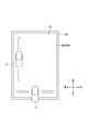
- FIG. 1 is a configuration diagram of a combination weighing device according to an embodiment.
- FIG. 2 is a diagram showing a configuration of an operation unit.
- FIG. 3 is a diagram illustrating a flick operation in the operation unit.
- FIG. 4 is a diagram showing a main screen of the operation unit.
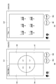
- FIG. 5A is a diagram showing a main screen
- FIG. 5B is a diagram showing an adjustment screen.
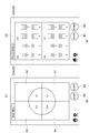
- FIG. 6A is a diagram showing a main screen
- FIG. 6B is a diagram showing an adjustment screen.
- FIG. 7A is a diagram showing a main screen
- FIG. 7B is a diagram showing a comprehensive display screen.
- FIG. 8A is a diagram showing a main screen
- FIG. 8B is a diagram showing a preset screen.
- the combination weighing device 1 includes a charging chute 2, a distributed feeder (conveying unit) 3, a plurality of radiating feeders (conveying unit) 4, a plurality of pool hoppers 5, and a plurality of measuring hoppers. 6, a collecting chute 7, a timing hopper 8, and a measuring unit 9 are provided.
- the combination weighing device 1 includes an operation unit 20.
- the combination weighing device 1 weighs the article A (an article having a variation in the mass of a single substance such as agricultural products, marine products, processed foods, etc.) supplied by the conveyor 15 so as to have a target weighing value, and is a bag-making and packaging machine. Supply to 16.
- the bag-making and packaging machine 16 forms the film into a bag having a predetermined capacity, and packs the article A that has been weighed and supplied by the combination weighing device 1.
- the charging chute 2 is arranged below the transport end 15a of the conveyor 15.
- the charging chute 2 receives the article A that has been conveyed from the outside by the transfer conveyor 15 and has fallen from the transfer end 15a of the transfer conveyor 15 and discharges it downward.
- the distributed feeder 3 is arranged below the input chute 2.
- the dispersion feeder 3 has a conical transport surface 3a that diverges downward. As the transport surface 3a is vibrated, the dispersion feeder 3 uniformly transports the article A discharged from the charging chute 2 to the top of the transport surface 3a toward the outer edge of the transport surface 3a.
- the plurality of radiating feeders 4 are arranged radially along the outer edge of the transport surface 3a of the dispersion feeder 3.
- Each radiating feeder 4 has a trough (conveying portion) 4a extending from below the outer edge of the transport surface 3a to the outside.
- Each radiant feeder 4 is vibrated to transport the article A discharged from the outer edge of the transport surface 3a toward the tip of the trough 4a.
- the plurality of pool hoppers 5 are arranged so as to surround, for example, a center line (not shown) parallel to the vertical direction. Each pool hopper 5 is arranged below the tip of the trough 4a of each radiation feeder 4. Each pool hopper 5 has a gate 5a that can be opened and closed relative to its bottom. By closing the gate 5a, each pool hopper 5 temporarily stores (retains) the article A discharged from the corresponding radiant feeder 4. Further, each pool hopper 5 opens the gate 5a to discharge the temporarily stored article A downward.
- the plurality of weighing hoppers 6 are arranged so as to surround the center line, for example. Each weighing hopper 6 is arranged below the gate 5a of each pool hopper 5. Each weighing hopper 6 has a gate 6a that can be opened and closed with respect to its bottom. Each weighing hopper 6 temporarily stores the article A discharged from the corresponding pool hopper 5 by closing the gate 6a. Further, each weighing hopper 6 discharges the temporarily stored article A downward by opening the gate 6a.
- the collecting chute 7 collects the articles A discharged from each weighing hopper 6.
- the collective chute 7 has an upper chute portion 7a and a lower chute portion 7b.
- the upper chute portion 7a receives the article A discharged from each measuring hopper 6 and slides the article A toward the lower chute portion 7b.
- the lower chute portion 7b is a truncated cone-shaped cylinder that tapers downward.
- the lower chute portion 7b discharges the article A to the timing hopper 8.
- the timing hopper 8 is arranged below the collective chute 7.
- the timing hopper 8 has a gate 8a that can be opened and closed with respect to the bottom thereof. By closing the gate 8a, the timing hopper 8 temporarily stores the article A discharged from the collecting chute 7. Further, the timing hopper 8 opens the gate 8a to discharge the temporarily stored article A to the bag making / packaging machine 16.
- the input chute 2, the dispersion feeder 3, the plurality of radiation feeders 4, the plurality of pool hoppers 5, and the plurality of measuring hoppers 6 are directly or indirectly supported by the support 11.
- the collective chute 7 and the timing hopper 8 are directly or indirectly supported by the frame 10.
- the measuring unit 9 is housed in the support 11 supported by the frame 10.
- the measuring unit 9 has a plurality of load cells 9a.
- Each load cell 9a supports a corresponding weighing hopper 6.
- the measuring unit 9 measures a weighing value according to the mass of the article A.
- the control unit 12 is arranged in the support 11.
- the control unit 12 has a CPU (Central Processing Unit), a ROM (Read Only Memory), a RAM (Random Access Memory), and the like.
- the control unit 12 transfers the distributed feeder 3 and the radiating feeder 4, opens and closes the gate 5a of each pool hopper 5, opens and closes the gate 6a of each measuring hopper 6, opens and closes the gate 8a of the timing hopper 8, and the like. Controls the operation of each part of the combination weighing device 1.
- the control unit 12 stores the measured value measured by the measuring unit 9 and the measuring hopper 6 for storing the article A corresponding to the measured value in association with each other.
- the control unit 12 calculates and selects a combination of measurement values from a plurality of measurement values measured by the measurement unit 9 and associated with each measurement hopper 6 so that the total value becomes the target measurement value (target value). To do. More specifically, the control unit 12 selects a combination of measurement values from a plurality of measurement values output by the measurement unit 9 so that the total value falls within a predetermined range with the target measurement value as the lower limit value. Then, the control unit 12 causes the measuring hopper 6 corresponding to the combination to discharge the article A.
- the operation unit 20 is an interface for a display device, a tablet terminal, or the like. As shown in FIG. 2, the operation unit 20 has a touch panel display 22.
- the touch panel display 22 is composed of, for example, a capacitance type touch panel.
- the touch panel display 22 has an operation surface 22a.
- the operation surface 22a accepts input by the operator.
- the operation unit 20 receives inputs such as a tap operation, a long press operation, a drag operation (swipe operation), and a flick operation.
- a tap operation such as a tap operation, a long press operation, a drag operation (swipe operation), and a flick operation.
- the flick operation after the finger F touches the operation surface 22a, the finger F is quickly moved while maintaining the touched state of the finger F, and the operation surface 22a is being moved while the finger F is being moved. This is a method of performing screen scrolling that continues for a certain period of time even after the finger F is released, based on the operation of releasing the finger F from the finger F.
- the flick operation the operation of moving the finger F in the up, down, right, and left directions with respect to the operation surface 22a can be performed.
- the operation unit 20 includes an input unit 24, an output unit 26, and a display control unit 28.
- the input unit 24 inputs information related to the distributed feeder 3, the plurality of radiation feeders 4, the plurality of pool hoppers 5, the plurality of measuring hoppers 6, and the timing hopper 8.
- the information includes operation information and the like related to the operation status of each part.
- the input unit 24 inputs various information output from the control unit 12.
- the output unit 26 outputs the setting information and the like set in the operation unit 20 to the control unit 12.
- the input unit 24 and the output unit 26 can communicate with the control unit 12.
- the display control unit 28 controls the display of the screen on the touch panel display 22.
- the display control unit 28 includes a CPU, ROM, RAM, and the like. As shown in FIG. 4, the display control unit 28 causes the touch panel display 22 to display the main screen G1.
- the main screen G1 is a screen displayed for managing and setting (adjusting) the combination weighing device 1, and is a screen set in advance.
- a "STOP" button B1 for stopping the operation of the combination weighing device 1 and a "START" button B2 for starting the operation of the combination weighing device 1 are displayed.
- a "home button", a "setting button” and the like are displayed on the main screen G1.
- the display control unit 28 displays the main screen G1 when the home button is pressed.
- various screens are displayed according to the flick operation, with the main screen G1 as the basic screen.
- Four channels (plural areas) C1, C2, C3, and C4 are displayed on the main screen G1.
- the combination weighing device 1 is divided into four channels C1 to C4 and displayed when the combination weighing device 1 is viewed from the vertical direction.
- the screen is divided into four areas A1, A2, A3, and A4 corresponding to the four channels C1 to C4.
- the setting range of each channel C1 to C4 can be arbitrarily set.
- each channel C1 to C4 can be selected one or more.
- the selection of each channel C1 to C4 is performed by tapping on the touch panel display 22.
- the display control unit 28 changes the colors of areas A1 to A4 corresponding to the selected channels C1 to C4, for example.
- the display control unit 28 changes the screen display according to the flick operation. Each screen is set for the moving direction of the flick operation.
- the display control unit 28 displays a screen associated with the moving direction of the flick operation on the touch panel display 22 according to the moving direction of the flick operation.
- the display control unit 28 displays the adjustment screen G2 shown in FIG. 5B when a flick operation for moving upward is performed on the main screen G1 shown in FIG. 5A. That is, the adjustment screen G2 is set for a flick operation that moves upward on the main screen G1.
- the adjustment screen G2 is a screen related to the operation of the dispersion feeder 3 and the radiation feeder 4, and is a screen for adjusting (setting) the dispersion feeder 3 and the radiation feeder 4.
- channel C1 and channel C2 are selected on the main screen G1. Therefore, as shown in FIG. 5B, the display control unit 28 displays the adjustment items and / or the operating status (“AAAA”, “BBBB”, etc.) of the channels C1 and C2 on the adjustment screen G2.
- the adjustment item is, for example, an item for adjusting parameters such as vibration time and vibration intensity.
- the display control unit 28 displays the main screen G1 shown in FIG. 5A when a flick operation for moving downward is performed on the adjustment screen G2 shown in FIG. 5B.
- the display control unit 28 displays the adjustment screen G3 shown in FIG. 6B when a flick operation for moving downward is performed on the main screen G1 shown in FIG. 6A. That is, the adjustment screen G3 is set for a flick operation that moves downward on the main screen G1.
- the adjustment screen G3 is a screen related to the operation of the pool hopper 5, the measuring hopper 6, and the timing hopper 8, and is a screen for adjusting the pool hopper 5, the measuring hopper 6, and the timing hopper 8.
- channel C1 is selected on the main screen G1. Therefore, as shown in FIG. 6B, the display control unit 28 displays the adjustment item and / or the operating status (“CCCC”, “DDDD”, etc.) of the channel C1 on the adjustment screen G2.
- the adjustment item is an item for adjusting parameters such as the timing of opening the hopper, for example.
- the hopper can be selected on the adjustment screen G3.
- Three hoppers are displayed on the adjustment screen G3.
- the three hoppers correspond to the pool hopper 5, the weighing hopper 6, and the timing hopper 8 in order from the top according to the configuration of the combination weighing device 1.
- FIG. 6B the weighing hopper 6 is selected.
- the display control unit 28 displays the adjustment item and / or the operating status corresponding to the selected hopper.
- the display control unit 28 displays the main screen G1 shown in FIG. 6A when a flick operation for moving upward is performed on the adjustment screen G3 shown in FIG. 6B.
- the display control unit 28 displays the comprehensive display screen G4 shown in FIG. 7B when a flick operation for moving to the right is performed on the main screen G1 shown in FIG. 7A. That is, the comprehensive display screen G4 is set for a flick operation to move to the right side on the main screen G1.
- the comprehensive display screen G4 displays the operating status, logs, and the like of the combination weighing device 1.
- the display control unit 28 displays the main screen G1 shown in FIG. 7A when a flick operation for moving to the left is performed on the comprehensive display screen G4 shown in FIG. 7B.
- the display control unit 28 displays the preset screen G5 shown in FIG. 8B when a flick operation for moving to the left is performed on the main screen G1 shown in FIG. 8A. That is, the preset screen G5 is set for a flick operation to move to the left side on the main screen G1.
- the preset screen G5 displays preset items for each channel C1 to C4.
- the display control unit 28 displays the main screen G1 shown in FIG. 8A when a flick operation for moving to the right is performed on the preset screen G5 shown in FIG. 8B.
- the display control unit 28 outputs the setting information indicating the setting contents such as the parameters input on the adjustment screens G2 and G3 to the output unit 26.
- the output unit 26 outputs the setting information to the control unit 12.
- the control unit 12 controls the operations of the distributed feeder 3, the plurality of radiation feeders 4, the plurality of pool hoppers 5, the plurality of weighing hoppers 6, and the timing hopper 8 according to the setting information.
- the operation unit 20 when the operation unit 20 receives a flick operation for moving upward with respect to the operation surface 22a, the distributed feeder 3 and the plurality of radiation feeders 4 operate.
- a flick operation for moving downward with respect to the operation surface 22a When a flick operation for moving downward with respect to the operation surface 22a is accepted, a screen related to the operation of the plurality of pool hoppers 5, the plurality of weighing hoppers 6, and the timing hopper 8 is displayed. ..
- the operator performs a flick operation to move upward on the operation surface 22a, for example, when confirming the setting or the operating state of the radiation feeder 4.
- the operation unit 20 in which the flick operation is performed displays a screen showing the setting and the operating state of the radiation feeder 4.
- the operator can intuitively perform the operation by associating the moving direction of the flick operation with each part of the combination weighing device 1.
- the dispersion feeder 3, the plurality of radiation feeders 4, the plurality of pool hoppers 5, the plurality of weighing hoppers 6, and the timing hopper 8 are arranged in the vertical direction.
- the display of the screen is changed by flicking in the vertical direction, so that the operator can intuitively perform the operation. Therefore, in the combination weighing device 1, the operability can be improved.
- the operation unit 20 when the operation unit 20 receives a flick operation on the preset main screen G1, the distributed feeder 3 and the plurality of radiation feeders 4 or a plurality of radiation feeders 4 or the like according to the flick operation.
- a screen showing information related to the operation of the plurality of pool hoppers 5, the plurality of weighing hoppers 6, and the timing hopper 8 is displayed.
- the main screen G1 may be a screen for starting an operation related to a setting or the like.
- the operation unit 20 changes the display according to the flick operation received on the main screen G1. As a result, the operation unit 20 can display the screen of the content intended by the operator. Therefore, in the combination weighing device 1, the operator can intuitively perform the operation.
- the operation unit 20 has a plurality of channels C1 to C4 for the distributed feeder 3, the plurality of radiation feeders 4, the plurality of pool hoppers 5, the plurality of weighing hoppers 6, and the timing hopper 8.
- the distributed feeders 3 and the plurality of distributed feeders corresponding to the selected channels C1 to C4 are received.
- a screen relating to the operation of the radiation feeder 4, the plurality of pool hoppers 5, the plurality of weighing hoppers 6, and the timing hopper 8 is displayed. In this configuration, it is possible to display only the information of the part that the operator wants to set. Therefore, in the combination weighing device 1, the operability can be further improved.
- the adjustment screen G2 may be displayed by performing a flick operation to move downward on the main screen G1.
- the adjustment screen G3 may be displayed by performing a flick operation to move upward on the main screen G1.
- the adjustment screen G2 may be displayed by performing a flick operation to move to either the right side or the left side on the main screen G1.
- the adjustment screen G3 may be displayed by performing a flick operation to move to either the right side or the left side on the main screen G1.
- the moving direction of the flick operation for displaying each screen may be appropriately set.
- the transfer unit (dispersion feeder 3, radiation feeder 4) and hopper (pool hopper 5, weighing hopper 6, timing).
- hopper weighing hopper 6, timing.
- a screen related to the operation of one of the hoppers 8 is displayed and a flick operation for moving downward or to the left with respect to the operation surface 22a is accepted, the screen related to the operation of the other of the transport unit and the hopper is displayed. It may be shown.
- the display control unit 28 may display a predetermined screen when a flick operation for moving to the right or left side is performed on the adjustment screens G2 and G3.
- the display control unit 28 may display a predetermined screen when a flick operation for moving to the upper side or the lower side is performed on the general display screen G4 or the preset screen G5.
- a mode of changing the screen display in response to a flick operation on the main screen G1 has been described as an example.
- changes to the display of various screens may be set for flick operations on screens other than the main screen G1.
- the embodiment in which the dispersion feeder 3 conveys the article A by vibration has been described as an example.
- the transport surface 3a may rotate to transport the article A.
- the radiation feeder 4 may be in the form of transporting the article A by a coil unit (screw) that can be driven to rotate or a belt conveyor.
- the control unit 12 controls the rotation speed (rpm) of the coil unit or the like as a conveying force.
- the control unit 12 controls the rotation speed of the rollers that drive the belt and the like.
Landscapes
- Physics & Mathematics (AREA)
- General Physics & Mathematics (AREA)
- Filling Or Emptying Of Bunkers, Hoppers, And Tanks (AREA)
- Basic Packing Technique (AREA)
- User Interface Of Digital Computer (AREA)
Abstract
組合せ計量装置1は、外部から供給される物品Aを搬送する搬送部と、搬送部から供給される物品を一時的に滞留させると共に物品Aを排出するホッパと、搬送部及びホッパの動作に係る情報を表示すると共に作業者による操作を受け付ける操作面22aを有する操作部20と、を備え、操作部20は、操作面22aに対して上側又は右側に移動するフリック操作を受け付けた場合、搬送部及びホッパのうちの一方の動作に係る画面を表示し、操作面22aに対して下側又は左側に移動するフリック操作を受け付けた場合、搬送部及びホッパのうちの他方の動作に係る画面を表示する。
Description
本発明は、組合せ計量装置に関する。
従来の組合せ計量装置として、例えば、特許文献1に記載された装置が知られている。特許文献1に記載の組合せ計量装置は、外部から供給される物品を搬送する搬送部と、搬送部から供給される物品を一時的に滞留させると共に物品を排出するホッパと、組合せ計量装置に行わせる操作内容を示す操作画面及び操作内容を手順通りに案内する案内画面を表示する表示部と、操作内容を入力する操作部と、を備える。特許文献1では、表示部及び操作部は、タッチパネルである。
従来の組合せ計量装置のように、搬送部やホッパの動作に係る設定等の操作は、作業者がタッチパネル等によって行う。従来の組合せ計量装置では、画面に表示されたタブを押下することによって操作対象を選択し、設定等を行っていた。このような組合せ計量装置の動作に係る設定等の操作は、作業者による操作性の向上のため、作業者がより直感的に行えることが好ましい。
本発明の一側面は、操作性の向上が図れる組合せ計量装置の提供を目的とする。
本発明の一側面に係る組合せ計量装置は、外部から供給される物品を搬送する搬送部と、搬送部から供給される物品を一時的に滞留させると共に物品を排出するホッパと、搬送部及びホッパの動作に係る情報を表示すると共に作業者による操作を受け付ける操作面を有する操作部と、を備え、操作部は、操作面に対して上側又は右側に移動するフリック操作を受け付けた場合、搬送部及びホッパのうちの一方の動作に係る画面を表示し、操作面に対して下側又は左側に移動するフリック操作を受け付けた場合、搬送部及びホッパのうちの他方の動作に係る画面を表示する。
本発明の一側面に係る組合せ計量装置では、操作部は、操作面に対して上側又は右側に移動するフリック操作を受け付けた場合、搬送部及びホッパのうちの一方の動作に係る画面を表示し、操作面に対して下側又は左側に移動するフリック操作を受け付けた場合、搬送部及びホッパのうちの他方の動作に係る画面を表示する。この構成では、作業者は、例えば搬送部の設定や稼動状態を確認する場合、操作面において例えば上側に移動するフリック操作を行う。このフリック操作が行われた操作部は、搬送部の設定や稼動状態を示す画面を表示する。このように、組合せ計量装置では、フリック操作の移動方向と組合せ計量装置の各部とを対応付けることにより、作業者が直感的に操作を行うことができる。したがって、組合せ計量装置では、操作性の向上が図れる。
一実施形態においては、操作部は、予め設定されたメイン画面においてフリック操作を受け付けた場合、当該フリック操作に応じて、搬送部又はホッパの動作に係る画面を表示してもよい。メイン画面は、設定等に係る操作を開始する画面となり得る。組合せ計量装置では、メイン画面において受け付けたフリック操作に応じて表示を変更する。これにより、組合せ計量装置では、作業者が意図する内容の画面を操作部に表示させることができる。したがって、組合せ計量装置では、作業者が直感的に操作を行うことができる。
一実施形態においては、操作部は、搬送部及びホッパについて複数の領域に分割して表示すると共に、複数の領域のそれぞれを選択する操作を受け付け、操作面においてフリック操作を受け付けた場合、選択された領域に対応する搬送部又はホッパの動作に係る画面を表示してもよい。この構成では、作業者が設定等を行いたい部分の情報のみを表示させることができる。したがって、組合せ計量装置では、操作性の向上がより一層図れる。
一実施形態においては、操作部は、操作面に対して上側に移動するフリック操作を受け付けた場合、搬送部及びホッパのうちの一方の動作に係る画面を表示し、操作面に対して下側に移動するフリック操作を受け付けた場合、搬送部及びホッパのうちの他方の動作に係る画面を表示してもよい。組合せ計量装置では、搬送部及びホッパは、上下方向において配置されている。そのため、組合せ計量装置では、上下方向のフリック操作によって画面の表示を変更するため、作業者がより直感的に操作を行うことができる。
一実施形態においては、操作部は、搬送部及びホッパの動作に係るパラメータを設定する画面を表示してもよい。この構成では、パラメータの設定の操作性の向上が図れる。
本発明の一側面によれば、操作性の向上が図れる。
以下、添付図面を参照して、本発明の好適な実施形態について詳細に説明する。なお、図面の説明において同一又は相当要素には同一符号を付し、重複する説明は省略する。
図1に示されるように、組合せ計量装置1は、投入シュート2と、分散フィーダ(搬送部)3と、複数の放射フィーダ(搬送部)4と、複数のプールホッパ5と、複数の計量ホッパ6と、集合シュート7と、タイミングホッパ8と、計量部9と、を備える。組合せ計量装置1は、操作部20を備える。
組合せ計量装置1は、搬送コンベア15によって供給される物品A(農産物、水産物、加工食品等のように、単体質量にばらつきのある物品)を目標計量値となるように計量して製袋包装機16に供給する。なお、製袋包装機16は、フィルムを所定容量の袋に成形しつつ、組合せ計量装置1によって計量されて供給された物品Aを袋詰めする。
投入シュート2は、搬送コンベア15の搬送端15aの下方に配置される。投入シュート2は、外部から搬送コンベア15によって搬送されて搬送コンベア15の搬送端15aから落下した物品Aを受けて下方に排出する。
分散フィーダ3は、投入シュート2の下方に配置される。分散フィーダ3は、下方に向かって末広がりの円錐状の搬送面3aを有する。分散フィーダ3は、搬送面3aが振動されることで、投入シュート2から搬送面3aの頂部に排出された物品Aを搬送面3aの外縁に向かって均一に搬送する。
複数の放射フィーダ4は、分散フィーダ3の搬送面3aの外縁に沿って放射状に配置される。各放射フィーダ4は、搬送面3aの外縁の下方から外側に延在するトラフ(搬送部)4aを有する。各放射フィーダ4は、振動されることで、搬送面3aの外縁から排出された物品Aをトラフ4aの先端部に向かって搬送する。
複数のプールホッパ5は、例えば鉛直方向に平行な中心線(図示省略)を囲むように配置される。各プールホッパ5は、各放射フィーダ4のトラフ4aの先端部の下方に配置される。各プールホッパ5は、その底部に対して開閉可能なゲート5aを有する。各プールホッパ5は、ゲート5aを閉じることで、対応する放射フィーダ4から排出された物品Aを一時的に貯留(滞留)する。更に、各プールホッパ5は、ゲート5aを開くことで、一時的に貯留した物品Aを下方に排出する。
複数の計量ホッパ6は、例えば上記中心線を囲むように配置される。各計量ホッパ6は、各プールホッパ5のゲート5aの下方に配置される。各計量ホッパ6は、その底部に対して開閉可能なゲート6aを有する。各計量ホッパ6は、ゲート6aを閉じることで、対応するプールホッパ5から排出された物品Aを一時的に貯留する。更に、各計量ホッパ6は、ゲート6aを開くことで、一時的に貯留した物品Aを下方に排出する。
集合シュート7は、各計量ホッパ6から排出された物品Aを集合させる。集合シュート7は、上段シュート部7aと、下段シュート部7bと、を有する。上段シュート部7aは、各計量ホッパ6から排出された物品Aを受けて当該物品Aを下段シュート部7b側に滑走させる。下段シュート部7bは、下方に向かって先細りの円錐台状の筒体である。下段シュート部7bは、物品Aをタイミングホッパ8に排出する。
タイミングホッパ8は、集合シュート7の下方に配置される。タイミングホッパ8は、その底部に対して開閉可能なゲート8aを有する。タイミングホッパ8は、ゲート8aを閉じることで、集合シュート7から排出された物品Aを一時的に貯留する。更に、タイミングホッパ8は、ゲート8aを開くことで、一時的に貯留した物品Aを製袋包装機16に排出する。
投入シュート2、分散フィーダ3、複数の放射フィーダ4、複数のプールホッパ5及び複数の計量ホッパ6は、支持体11に直接的に又は間接的に支持される。集合シュート7及びタイミングホッパ8は、フレーム10に直接的に又は間接的に支持される。
計量部9は、フレーム10に支持された支持体11内に収容される。計量部9は、複数のロードセル9aを有する。各ロードセル9aは、対応する計量ホッパ6を支持する。計量部9は、各計量ホッパ6に物品Aが一時的に貯留される際に、当該物品Aの質量に応じた計量値を計量する。
制御部12は、支持体11内に配置される。制御部12は、CPU(Central Processing Unit)、ROM(Read Only Memory)、RAM(Random Access Memory)等を有する。制御部12は、分散フィーダ3及び放射フィーダ4の搬送動作、各プールホッパ5のゲート5aの開閉動作、各計量ホッパ6のゲート6aの開閉動作、並びにタイミングホッパ8のゲート8aの開閉動作等、組合せ計量装置1の各部の動作を制御する。
制御部12は、計量部9によって計量された計量値と、当該計量値に対応する物品Aを貯留する計量ホッパ6とを対応付けて記憶する。制御部12は、計量部9によって計量され且つ各計量ホッパ6に対応付けられた複数の計量値から、合計値が目標計量値(目標値)となるように計量値の組合せを計算して選択する。より具体的には、制御部12は、計量部9によって出力された複数の計量値から、目標計量値を下限値とする所定範囲内に合計値が収まるように計量値の組合せを選択する。そして、制御部12は、当該組合せに対応する計量ホッパ6に物品Aを排出させる。
操作部20は、表示装置又はタブレット端末等のインターフェースである。図2に示されるように、操作部20は、タッチパネルディスプレイ22を有する。タッチパネルディスプレイ22は、例えば、静電容量方式のタッチパネルで構成される。タッチパネルディスプレイ22は、操作面22aを有する。
操作面22aは、作業者による入力を受け付ける。操作部20は、タップ操作、長押し操作、ドラッグ操作(スワイプ操作)、及び、フリック操作等の入力を受け付ける。図3に示されるように、フリック操作は、操作面22aに指Fが触れた後、指Fが触れた状態を維持しながら素早く指Fを動かし、指Fを動かしている途中で操作面22aから指Fを離す操作に基づいて、指Fが離れた後も一定時間持続する画面スクロールを行う方法である。フリック操作においては、操作面22aに対して、上、下、右、左方向に指Fを動かす操作が行われ得る。
図2に示されるように、操作部20は、入力部24と、出力部26と、表示制御部28と、を有する。入力部24は、分散フィーダ3、複数の放射フィーダ4、複数のプールホッパ5、複数の計量ホッパ6及びタイミングホッパ8に係る情報を入力する。当該情報は、各部の稼動状況に係る稼動情報等を含む。入力部24は、制御部12から出力された各種情報を入力する。出力部26は、操作部20において設定された設定情報等を制御部12に出力する。入力部24及び出力部26は、制御部12と通信可能である。
表示制御部28は、タッチパネルディスプレイ22における画面の表示を制御する。表示制御部28は、CPU、ROM、RAM等を有する。図4に示されるように、表示制御部28は、タッチパネルディスプレイ22にメイン画面G1を表示させる。メイン画面G1は、組合せ計量装置1の管理及び設定(調整)を行うために表示される画面であり、予め設定される画面である。メイン画面G1には、組合せ計量装置1の動作を停止させる「STOP」ボタンB1と、組合せ計量装置1の動作を開始させる「START」ボタンB2と、が表示される。また、メイン画面G1には、「ホームボタン」及び「セッティングボタン」等が表示される。表示制御部28は、ホームボタンが押下されると、メイン画面G1を表示する。
操作部20では、メイン画面G1を基本画面として、フリック操作に応じて各種画面が表示される。メイン画面G1には、4つのチャンネル(複数の領域)C1,C2,C3,C4が表示される。メイン画面G1では、組合せ計量装置1を鉛直方向から見た状態において、組合せ計量装置1をチャンネルC1~C4の4つに区画して表示する。メイン画面G1では、4つのチャンネルC1~C4に対応して、4つのエリアA1,A2,A3,A4に画面が区画される。各チャンネルC1~C4の設定範囲は、任意に設定可能である。
メイン画面G1において、各チャンネルC1~C4は、一又は複数の選択が可能である。各チャンネルC1~C4の選択は、タッチパネルディスプレイ22においてタップ操作によって行う。表示制御部28は、チャンネルC1~C4が選択されると、例えば、選択されたチャンネルC1~C4に対応するエリアA1~A4の色を変更する。
表示制御部28は、フリック操作に応じて、画面の表示を変更する。各画面は、フリック操作の移動方向に対して設定される。表示制御部28は、フリック操作の移動方向に応じて、フリック操作の移動方向に対応付けられた画面をタッチパネルディスプレイ22に表示する。
本実施形態では、表示制御部28は、図5(a)に示されるメイン画面G1において、上側に移動するフリック操作が行われると、図5(b)に示される調整画面G2を表示する。すなわち、調整画面G2は、メイン画面G1における上側に移動するフリック操作に対して設定される。調整画面G2は、分散フィーダ3及び放射フィーダ4の動作に係る画面であり、分散フィーダ3及び放射フィーダ4の調整(設定)を行うための画面である。図5(a)に示されるように、メイン画面G1では、チャンネルC1及びチャンネルC2が選択されている。そのため、表示制御部28は、図5(b)に示されるように、調整画面G2において、チャンネルC1及びチャンネルC2の調整項目及び/又は稼動状況(「AAAA」、「BBBB」等)を表示する。調整項目は、例えば、振動時間、振動強度等のパラメータを調整する項目である。表示制御部28は、図5(b)において示される調整画面G2において、下側に移動するフリック操作が行われると、図5(a)に示されるメイン画面G1を表示する。
表示制御部28は、図6(a)に示されるメイン画面G1において、下側に移動するフリック操作が行われると、図6(b)に示される調整画面G3を表示する。すなわち、調整画面G3は、メイン画面G1における下側に移動するフリック操作に対して設定される。調整画面G3は、プールホッパ5、計量ホッパ6及びタイミングホッパ8の動作に係る画面であり、プールホッパ5、計量ホッパ6及びタイミングホッパ8の調整を行うための画面である。図6(a)に示されるように、メイン画面G1では、チャンネルC1が選択されている。そのため、表示制御部28は、図6(b)に示されるように、調整画面G2において、チャンネルC1の調整項目及び/又は稼動状況(「CCCC」、「DDDD」等)を表示する。調整項目は、例えば、ホッパを開くタイミング等のパラメータを調整する項目である。
調整画面G3では、ホッパが選択可能である。調整画面G3には、3つのホッパが表示される。3つのホッパは、組合せ計量装置1の構成に合わせて、上から順に、プールホッパ5、計量ホッパ6及びタイミングホッパ8に対応する。図6(b)では、計量ホッパ6が選択されている。表示制御部28は、選択されたホッパに対応する調整項目及び/又は稼動状況を表示する。表示制御部28は、図6(b)において示される調整画面G3において、上側に移動するフリック操作が行われると、図6(a)に示されるメイン画面G1を表示する。
表示制御部28は、図7(a)に示されるメイン画面G1において、右側に移動するフリック操作が行われると、図7(b)に示される総合表示画面G4を表示する。すなわち、総合表示画面G4は、メイン画面G1における右側に移動するフリック操作に対して設定される。総合表示画面G4は、組合せ計量装置1の稼動状態やログ等を表示する。表示制御部28は、図7(b)において示される総合表示画面G4において、左側に移動するフリック操作が行われると、図7(a)に示されるメイン画面G1を表示する。
表示制御部28は、図8(a)に示されるメイン画面G1において、左側に移動するフリック操作が行われると、図8(b)に示されるプリセット画面G5を表示する。すなわち、プリセット画面G5は、メイン画面G1における左側に移動するフリック操作に対して設定される。プリセット画面G5は、各チャンネルC1~C4のプリセット項目を表示する。表示制御部28は、図8(b)において示されるプリセット画面G5において、右側に移動するフリック操作が行われると、図8(a)に示されるメイン画面G1を表示する。
表示制御部28は、調整画面G2,G3において入力されたパラメータ等の設定内容を示す設定情報を出力部26に出力する。出力部26は、設定情報を制御部12に出力する。制御部12は、設定情報に応じて、分散フィーダ3、複数の放射フィーダ4、複数のプールホッパ5、複数の計量ホッパ6、及び、タイミングホッパ8の動作を制御する。
以上説明したように、本実施形態に係る組合せ計量装置1では、操作部20は、操作面22aに対して上側に移動するフリック操作を受け付けた場合、分散フィーダ3及び複数の放射フィーダ4の動作に係る画面を表示し、操作面22aに対して下側に移動するフリック操作を受け付けた場合、複数のプールホッパ5、複数の計量ホッパ6、及び、タイミングホッパ8の動作に係る画面を表示する。この構成では、作業者は、例えば放射フィーダ4の設定や稼動状態を確認する場合、操作面22aにおいて上側に移動するフリック操作を行う。このフリック操作が行われた操作部20は、放射フィーダ4の設定や稼動状態を示す画面を表示する。このように、組合せ計量装置1では、フリック操作の移動方向と組合せ計量装置1の各部とを対応付けることにより、作業者が直感的に操作を行うことができる。特に、組合せ計量装置1では、分散フィーダ3及び複数の放射フィーダ4、及び、複数のプールホッパ5、複数の計量ホッパ6及びタイミングホッパ8は、上下方向において配置されている。この構成において、組合せ計量装置1では、上下方向のフリック操作によって画面の表示を変更するため、作業者が直感的に操作を行うことができる。したがって、組合せ計量装置1では、操作性の向上が図れる。
本実施形態に係る組合せ計量装置1では、操作部20は、予め設定されたメイン画面G1においてフリック操作を受け付けた場合、当該フリック操作に応じて、分散フィーダ3及び複数の放射フィーダ4、又は、複数のプールホッパ5、複数の計量ホッパ6、及び、タイミングホッパ8の動作に係る情報を示す画面を表示する。メイン画面G1は、設定等に係る操作を開始する画面となり得る。操作部20では、メイン画面G1において受け付けたフリック操作に応じて表示を変更する。これにより、操作部20では、作業者が意図する内容の画面を表示させることができる。したがって、組合せ計量装置1では、作業者が直感的に操作を行うことができる。
本実施形態に係る組合せ計量装置1では、操作部20は、分散フィーダ3、複数の放射フィーダ4、複数のプールホッパ5、複数の計量ホッパ6、及び、タイミングホッパ8について複数のチャンネルC1~C4に分割して表示すると共に、複数のチャンネルC1~C4のそれぞれを選択する操作を受け付け、操作面22aにおいてフリック操作を受け付けた場合、選択されたチャンネルC1~C4に対応する分散フィーダ3及び複数の放射フィーダ4、又は、複数のプールホッパ5、複数の計量ホッパ6、及び、タイミングホッパ8の動作に係る画面を表示する。この構成では、作業者が設定等を行いたい部分の情報のみを表示させることができる。したがって、組合せ計量装置1では、操作性の向上がより一層図れる。
以上、本発明の実施形態について説明してきたが、本発明は必ずしも上述した実施形態に限定されるものではなく、その要旨を逸脱しない範囲で様々な変更が可能である。
上記実施形態では、表示制御部28が、メイン画面G1において、上側に移動するフリック操作が行われると調整画面G2を表示する形態を一例に説明した。しかし、調整画面G2は、メイン画面G1において下側に移動するフリック操作がおこなわれることによって表示されてもよい。この場合、調整画面G3は、メイン画面G1において上側に移動するフリック操作がおこなわれることによって表示されてもよい。また、調整画面G2は、メイン画面G1において右側及び左側の一方に移動するフリック操作がおこなわれることによって表示されてもよい。この場合、調整画面G3は、メイン画面G1においてに右側及び左側の一方に移動するフリック操作がおこなわれることによって表示されてもよい。各画面を表示させるフリック操作の移動方向は、適宜設定されればよい。要は、操作部20は、操作面22aに対して上側又は右側に移動するフリック操作を受け付けた場合、搬送部(分散フィーダ3、放射フィーダ4)及びホッパ(プールホッパ5、計量ホッパ6、タイミングホッパ8)のうちの一方の動作に係る画面を表示し、操作面22aに対して下側又は左側に移動するフリック操作を受け付けた場合、搬送部及びホッパのうちの他方の動作に係る画面を表示すればよい。
また、表示制御部28は、調整画面G2,G3において右側又は左側に移動するフリック操作が行われた場合、所定の画面を表示させてもよい。表示制御部28は、総合表示画面G4又はプリセット画面G5において上側又は下側に移動するフリック操作が行われた場合、所定の画面を表示させてもよい。
上記実施形態では、メイン画面G1におけるフリック操作に対して、画面の表示を変更する形態を一例に説明した。しかし、メイン画面G1以外の画面におけるフリック操作に対して、各種画面の表示の変更が設定されてもよい。
上記実施形態では、分散フィーダ3が振動によって物品Aを搬送する形態を一例に説明した。しかし、分散フィーダ3は、搬送面3aが回転して物品Aを搬送してもよい。
上記実施形態では、放射フィーダ4が振動によって物品Aを搬送する形態を一例に説明した。しかし、放射フィーダ4は、回転駆動可能なコイルユニット(スクリュー)、又は、ベルトコンベアによって物品Aを搬送する形態であってもよい。コイルユニットの場合には、制御部12は、搬送力として、コイルユニットの回転数(rpm)等を制御する。また、ベルトコンベアの場合には、制御部12は、ベルトを駆動させるローラの回転数等を制御する。
1…組合せ計量装置、3…分散フィーダ(搬送部)、4…放射フィーダ(搬送部)、5…プールホッパ(ホッパ)、6…計量ホッパ(ホッパ)、8…タイミングホッパ(ホッパ)、20…操作部、22a…操作面、A…物品、C1~C4…チャンネル(領域)。
Claims (5)
- 外部から供給される物品を搬送する搬送部と、
前記搬送部から供給される前記物品を一時的に滞留させると共に前記物品を排出するホッパと、
前記搬送部及び前記ホッパの動作に係る情報を表示すると共に作業者による操作を受け付ける操作面を有する操作部と、を備え、
前記操作部は、
前記操作面に対して上側又は右側に移動するフリック操作を受け付けた場合、前記搬送部及び前記ホッパのうちの一方の動作に係る画面を表示し、
前記操作面に対して下側又は左側に移動するフリック操作を受け付けた場合、前記搬送部及び前記ホッパのうちの他方の動作に係る画面を表示する、組合せ計量装置。 - 前記操作部は、予め設定されたメイン画面において前記フリック操作を受け付けた場合、当該フリック操作に応じて、前記搬送部又は前記ホッパの動作に係る画面を表示させる、請求項1に記載の組合せ計量装置。
- 前記操作部は、
前記搬送部及び前記ホッパについて複数の領域に分割して表示すると共に、複数の前記領域のそれぞれを選択する操作を受け付け、
前記操作面においてフリック操作を受け付けた場合、選択された前記領域に対応する前記搬送部又は前記ホッパの動作に係る画面を表示する、請求項1又は2に記載の組合せ計量装置。 - 前記操作部は、
前記操作面に対して上側に移動するフリック操作を受け付けた場合、前記搬送部及び前記ホッパのうちの一方の動作に係る画面を表示し、
前記操作面に対して下側に移動するフリック操作を受け付けた場合、前記搬送部及び前記ホッパのうちの他方の動作に係る画面を表示する、請求項1~3のいずれか一項に記載の組合せ計量装置。 - 前記操作部は、前記搬送部及び前記ホッパの動作に係るパラメータを設定する画面を表示する、請求項1~4のいずれか一項に記載の組合せ計量装置。
Priority Applications (2)
| Application Number | Priority Date | Filing Date | Title |
|---|---|---|---|
| CN202080005963.4A CN112997053A (zh) | 2019-06-25 | 2020-03-24 | 组合计量装置 |
| EP20830759.5A EP3992593A4 (en) | 2019-06-25 | 2020-03-24 | COMBI MEASUREMENT DEVICE |
Applications Claiming Priority (2)
| Application Number | Priority Date | Filing Date | Title |
|---|---|---|---|
| JP2019-117443 | 2019-06-25 | ||
| JP2019117443A JP2021004756A (ja) | 2019-06-25 | 2019-06-25 | 組合せ計量装置 |
Publications (1)
| Publication Number | Publication Date |
|---|---|
| WO2020261679A1 true WO2020261679A1 (ja) | 2020-12-30 |
Family
ID=74061112
Family Applications (1)
| Application Number | Title | Priority Date | Filing Date |
|---|---|---|---|
| PCT/JP2020/013101 Ceased WO2020261679A1 (ja) | 2019-06-25 | 2020-03-24 | 組合せ計量装置 |
Country Status (4)
| Country | Link |
|---|---|
| EP (1) | EP3992593A4 (ja) |
| JP (1) | JP2021004756A (ja) |
| CN (1) | CN112997053A (ja) |
| WO (1) | WO2020261679A1 (ja) |
Cited By (1)
| Publication number | Priority date | Publication date | Assignee | Title |
|---|---|---|---|---|
| EP3859465A1 (en) * | 2020-01-30 | 2021-08-04 | ISHIDA CO., Ltd. | Bag-making and packaging apparatus |
Citations (6)
| Publication number | Priority date | Publication date | Assignee | Title |
|---|---|---|---|---|
| JP2003316418A (ja) | 2002-04-24 | 2003-11-07 | Ishida Co Ltd | 商品製造装置 |
| US20040016765A1 (en) * | 2002-06-24 | 2004-01-29 | John Baranowski | Control systems and methods of dispensing items |
| JP2012230020A (ja) * | 2011-04-27 | 2012-11-22 | Yamato Scale Co Ltd | 操作制御装置 |
| WO2015115475A1 (ja) * | 2014-01-30 | 2015-08-06 | 株式会社イシダ | 組合せ計量装置 |
| WO2016043324A1 (ja) * | 2014-09-19 | 2016-03-24 | 株式会社イシダ | 分散供給装置及び組合せ計量装置 |
| JP2016133940A (ja) * | 2015-01-16 | 2016-07-25 | コニカミノルタ株式会社 | 画像形成装置およびプログラム |
Family Cites Families (6)
| Publication number | Priority date | Publication date | Assignee | Title |
|---|---|---|---|---|
| JP5288947B2 (ja) * | 2008-08-29 | 2013-09-11 | 大和製衡株式会社 | 組合せ秤 |
| JP5199325B2 (ja) * | 2010-10-14 | 2013-05-15 | シャープ株式会社 | 情報入力装置及び画像形成装置 |
| JP6144582B2 (ja) * | 2013-09-13 | 2017-06-07 | Dmg森精機株式会社 | Nc工作機械の操作装置 |
| US20180111711A1 (en) * | 2015-05-26 | 2018-04-26 | Ishida Co., Ltd. | Production line configuration apparatus |
| JP2017091441A (ja) * | 2015-11-17 | 2017-05-25 | 株式会社ディスコ | 操作タッチパネル装置 |
| JP2017182153A (ja) * | 2016-03-28 | 2017-10-05 | 京セラドキュメントソリューションズ株式会社 | 表示操作装置及び操作指示受付プログラム |
-
2019
- 2019-06-25 JP JP2019117443A patent/JP2021004756A/ja active Pending
-
2020
- 2020-03-24 WO PCT/JP2020/013101 patent/WO2020261679A1/ja not_active Ceased
- 2020-03-24 EP EP20830759.5A patent/EP3992593A4/en not_active Withdrawn
- 2020-03-24 CN CN202080005963.4A patent/CN112997053A/zh active Pending
Patent Citations (6)
| Publication number | Priority date | Publication date | Assignee | Title |
|---|---|---|---|---|
| JP2003316418A (ja) | 2002-04-24 | 2003-11-07 | Ishida Co Ltd | 商品製造装置 |
| US20040016765A1 (en) * | 2002-06-24 | 2004-01-29 | John Baranowski | Control systems and methods of dispensing items |
| JP2012230020A (ja) * | 2011-04-27 | 2012-11-22 | Yamato Scale Co Ltd | 操作制御装置 |
| WO2015115475A1 (ja) * | 2014-01-30 | 2015-08-06 | 株式会社イシダ | 組合せ計量装置 |
| WO2016043324A1 (ja) * | 2014-09-19 | 2016-03-24 | 株式会社イシダ | 分散供給装置及び組合せ計量装置 |
| JP2016133940A (ja) * | 2015-01-16 | 2016-07-25 | コニカミノルタ株式会社 | 画像形成装置およびプログラム |
Non-Patent Citations (1)
| Title |
|---|
| See also references of EP3992593A4 |
Cited By (1)
| Publication number | Priority date | Publication date | Assignee | Title |
|---|---|---|---|---|
| EP3859465A1 (en) * | 2020-01-30 | 2021-08-04 | ISHIDA CO., Ltd. | Bag-making and packaging apparatus |
Also Published As
| Publication number | Publication date |
|---|---|
| JP2021004756A (ja) | 2021-01-14 |
| EP3992593A4 (en) | 2023-01-25 |
| EP3992593A1 (en) | 2022-05-04 |
| CN112997053A (zh) | 2021-06-18 |
Similar Documents
| Publication | Publication Date | Title |
|---|---|---|
| EP0978711A1 (en) | Weighing and packaging system | |
| US4780830A (en) | Combination weighing and packing system | |
| WO2020261679A1 (ja) | 組合せ計量装置 | |
| WO2017154819A1 (ja) | 組合せ計量装置 | |
| US20190023429A1 (en) | Combination weighing device | |
| JP6484052B2 (ja) | 組合せ計量装置 | |
| EP3859465A1 (en) | Bag-making and packaging apparatus | |
| US11971292B2 (en) | Combinatorial weighing device | |
| JP2004177375A (ja) | 組合せ計量装置 | |
| JP7323921B2 (ja) | 組合せ計量装置 | |
| JP4245903B2 (ja) | 組合せ計量計数装置 | |
| JP2007248199A (ja) | 組合せ計量装置 | |
| JP5188102B2 (ja) | 箱詰め装置 | |
| WO2019203030A1 (ja) | 組合せ計量装置 | |
| JP5123075B2 (ja) | 計量機器用情報処理装置 | |
| JP5547536B2 (ja) | 組み合わせ秤及び組み合わせ秤における計量方法 | |
| JP2020191798A (ja) | 米飯供給装置 | |
| JP6808293B2 (ja) | 組合せ秤 | |
| JP5669097B2 (ja) | 組合せ秤 | |
| JP7701040B2 (ja) | 組合せ計量装置 | |
| JP6062237B2 (ja) | 組合せ秤 | |
| JP5203813B2 (ja) | 計量包装システム及び組合せ秤 | |
| JPH05180687A (ja) | 組合せ計量装置 | |
| JPH05147601A (ja) | 計量包装システム | |
| JP2018155636A (ja) | 分散装置及び組合せ計量装置 |
Legal Events
| Date | Code | Title | Description |
|---|---|---|---|
| 121 | Ep: the epo has been informed by wipo that ep was designated in this application |
Ref document number: 20830759 Country of ref document: EP Kind code of ref document: A1 |
|
| NENP | Non-entry into the national phase |
Ref country code: DE |
|
| ENP | Entry into the national phase |
Ref document number: 2020830759 Country of ref document: EP Effective date: 20220125 |