WO2021014796A1 - Balle de caoutchouc acrylique excellente en termes de stabilite au stockage et d'aptitude au formage - Google Patents
Balle de caoutchouc acrylique excellente en termes de stabilite au stockage et d'aptitude au formage Download PDFInfo
- Publication number
- WO2021014796A1 WO2021014796A1 PCT/JP2020/022319 JP2020022319W WO2021014796A1 WO 2021014796 A1 WO2021014796 A1 WO 2021014796A1 JP 2020022319 W JP2020022319 W JP 2020022319W WO 2021014796 A1 WO2021014796 A1 WO 2021014796A1
- Authority
- WO
- WIPO (PCT)
- Prior art keywords
- acrylic rubber
- weight
- rubber
- acrylic
- water
- Prior art date
- Legal status (The legal status is an assumption and is not a legal conclusion. Google has not performed a legal analysis and makes no representation as to the accuracy of the status listed.)
- Ceased
Links
Images
Classifications
-
- C—CHEMISTRY; METALLURGY
- C08—ORGANIC MACROMOLECULAR COMPOUNDS; THEIR PREPARATION OR CHEMICAL WORKING-UP; COMPOSITIONS BASED THEREON
- C08F—MACROMOLECULAR COMPOUNDS OBTAINED BY REACTIONS ONLY INVOLVING CARBON-TO-CARBON UNSATURATED BONDS
- C08F2/00—Processes of polymerisation
- C08F2/12—Polymerisation in non-solvents
- C08F2/16—Aqueous medium
- C08F2/22—Emulsion polymerisation
- C08F2/24—Emulsion polymerisation with the aid of emulsifying agents
-
- C—CHEMISTRY; METALLURGY
- C08—ORGANIC MACROMOLECULAR COMPOUNDS; THEIR PREPARATION OR CHEMICAL WORKING-UP; COMPOSITIONS BASED THEREON
- C08L—COMPOSITIONS OF MACROMOLECULAR COMPOUNDS
- C08L33/00—Compositions of homopolymers or copolymers of compounds having one or more unsaturated aliphatic radicals, each having only one carbon-to-carbon double bond, and only one being terminated by only one carboxyl radical, or of salts, anhydrides, esters, amides, imides or nitriles thereof; Compositions of derivatives of such polymers
- C08L33/04—Homopolymers or copolymers of esters
- C08L33/06—Homopolymers or copolymers of esters of esters containing only carbon, hydrogen and oxygen, which oxygen atoms are present only as part of the carboxyl radical
-
- C—CHEMISTRY; METALLURGY
- C08—ORGANIC MACROMOLECULAR COMPOUNDS; THEIR PREPARATION OR CHEMICAL WORKING-UP; COMPOSITIONS BASED THEREON
- C08K—Use of inorganic or non-macromolecular organic substances as compounding ingredients
- C08K3/00—Use of inorganic substances as compounding ingredients
- C08K3/02—Elements
- C08K3/08—Metals
-
- B—PERFORMING OPERATIONS; TRANSPORTING
- B29—WORKING OF PLASTICS; WORKING OF SUBSTANCES IN A PLASTIC STATE IN GENERAL
- B29B—PREPARATION OR PRETREATMENT OF THE MATERIAL TO BE SHAPED; MAKING GRANULES OR PREFORMS; RECOVERY OF PLASTICS OR OTHER CONSTITUENTS OF WASTE MATERIAL CONTAINING PLASTICS
- B29B11/00—Making preforms
- B29B11/06—Making preforms by moulding the material
- B29B11/10—Extrusion moulding
-
- C—CHEMISTRY; METALLURGY
- C08—ORGANIC MACROMOLECULAR COMPOUNDS; THEIR PREPARATION OR CHEMICAL WORKING-UP; COMPOSITIONS BASED THEREON
- C08C—TREATMENT OR CHEMICAL MODIFICATION OF RUBBERS
- C08C1/00—Treatment of rubber latex
- C08C1/14—Coagulation
- C08C1/15—Coagulation characterised by the coagulants used
-
- C—CHEMISTRY; METALLURGY
- C08—ORGANIC MACROMOLECULAR COMPOUNDS; THEIR PREPARATION OR CHEMICAL WORKING-UP; COMPOSITIONS BASED THEREON
- C08F—MACROMOLECULAR COMPOUNDS OBTAINED BY REACTIONS ONLY INVOLVING CARBON-TO-CARBON UNSATURATED BONDS
- C08F2/00—Processes of polymerisation
- C08F2/12—Polymerisation in non-solvents
- C08F2/16—Aqueous medium
- C08F2/22—Emulsion polymerisation
- C08F2/24—Emulsion polymerisation with the aid of emulsifying agents
- C08F2/26—Emulsion polymerisation with the aid of emulsifying agents anionic
-
- C—CHEMISTRY; METALLURGY
- C08—ORGANIC MACROMOLECULAR COMPOUNDS; THEIR PREPARATION OR CHEMICAL WORKING-UP; COMPOSITIONS BASED THEREON
- C08F—MACROMOLECULAR COMPOUNDS OBTAINED BY REACTIONS ONLY INVOLVING CARBON-TO-CARBON UNSATURATED BONDS
- C08F2/00—Processes of polymerisation
- C08F2/12—Polymerisation in non-solvents
- C08F2/16—Aqueous medium
- C08F2/22—Emulsion polymerisation
- C08F2/24—Emulsion polymerisation with the aid of emulsifying agents
- C08F2/30—Emulsion polymerisation with the aid of emulsifying agents non-ionic
-
- C—CHEMISTRY; METALLURGY
- C08—ORGANIC MACROMOLECULAR COMPOUNDS; THEIR PREPARATION OR CHEMICAL WORKING-UP; COMPOSITIONS BASED THEREON
- C08F—MACROMOLECULAR COMPOUNDS OBTAINED BY REACTIONS ONLY INVOLVING CARBON-TO-CARBON UNSATURATED BONDS
- C08F20/00—Homopolymers and copolymers of compounds having one or more unsaturated aliphatic radicals, each having only one carbon-to-carbon double bond, and only one being terminated by only one carboxyl radical or a salt, anhydride, ester, amide, imide or nitrile thereof
- C08F20/02—Monocarboxylic acids having less than ten carbon atoms, Derivatives thereof
- C08F20/10—Esters
- C08F20/12—Esters of monohydric alcohols or phenols
- C08F20/16—Esters of monohydric alcohols or phenols of phenols or of alcohols containing two or more carbon atoms
- C08F20/18—Esters of monohydric alcohols or phenols of phenols or of alcohols containing two or more carbon atoms with acrylic or methacrylic acids
-
- C—CHEMISTRY; METALLURGY
- C08—ORGANIC MACROMOLECULAR COMPOUNDS; THEIR PREPARATION OR CHEMICAL WORKING-UP; COMPOSITIONS BASED THEREON
- C08F—MACROMOLECULAR COMPOUNDS OBTAINED BY REACTIONS ONLY INVOLVING CARBON-TO-CARBON UNSATURATED BONDS
- C08F220/00—Copolymers of compounds having one or more unsaturated aliphatic radicals, each having only one carbon-to-carbon double bond, and only one being terminated by only one carboxyl radical or a salt, anhydride ester, amide, imide or nitrile thereof
- C08F220/02—Monocarboxylic acids having less than ten carbon atoms; Derivatives thereof
- C08F220/10—Esters
- C08F220/12—Esters of monohydric alcohols or phenols
- C08F220/16—Esters of monohydric alcohols or phenols of phenols or of alcohols containing two or more carbon atoms
- C08F220/18—Esters of monohydric alcohols or phenols of phenols or of alcohols containing two or more carbon atoms with acrylic or methacrylic acids
-
- C—CHEMISTRY; METALLURGY
- C08—ORGANIC MACROMOLECULAR COMPOUNDS; THEIR PREPARATION OR CHEMICAL WORKING-UP; COMPOSITIONS BASED THEREON
- C08F—MACROMOLECULAR COMPOUNDS OBTAINED BY REACTIONS ONLY INVOLVING CARBON-TO-CARBON UNSATURATED BONDS
- C08F220/00—Copolymers of compounds having one or more unsaturated aliphatic radicals, each having only one carbon-to-carbon double bond, and only one being terminated by only one carboxyl radical or a salt, anhydride ester, amide, imide or nitrile thereof
- C08F220/02—Monocarboxylic acids having less than ten carbon atoms; Derivatives thereof
- C08F220/10—Esters
- C08F220/12—Esters of monohydric alcohols or phenols
- C08F220/16—Esters of monohydric alcohols or phenols of phenols or of alcohols containing two or more carbon atoms
- C08F220/18—Esters of monohydric alcohols or phenols of phenols or of alcohols containing two or more carbon atoms with acrylic or methacrylic acids
- C08F220/1802—C2-(meth)acrylate, e.g. ethyl (meth)acrylate
-
- C—CHEMISTRY; METALLURGY
- C08—ORGANIC MACROMOLECULAR COMPOUNDS; THEIR PREPARATION OR CHEMICAL WORKING-UP; COMPOSITIONS BASED THEREON
- C08F—MACROMOLECULAR COMPOUNDS OBTAINED BY REACTIONS ONLY INVOLVING CARBON-TO-CARBON UNSATURATED BONDS
- C08F220/00—Copolymers of compounds having one or more unsaturated aliphatic radicals, each having only one carbon-to-carbon double bond, and only one being terminated by only one carboxyl radical or a salt, anhydride ester, amide, imide or nitrile thereof
- C08F220/02—Monocarboxylic acids having less than ten carbon atoms; Derivatives thereof
- C08F220/10—Esters
- C08F220/12—Esters of monohydric alcohols or phenols
- C08F220/16—Esters of monohydric alcohols or phenols of phenols or of alcohols containing two or more carbon atoms
- C08F220/18—Esters of monohydric alcohols or phenols of phenols or of alcohols containing two or more carbon atoms with acrylic or methacrylic acids
- C08F220/1804—C4-(meth)acrylate, e.g. butyl (meth)acrylate, isobutyl (meth)acrylate or tert-butyl (meth)acrylate
-
- C—CHEMISTRY; METALLURGY
- C08—ORGANIC MACROMOLECULAR COMPOUNDS; THEIR PREPARATION OR CHEMICAL WORKING-UP; COMPOSITIONS BASED THEREON
- C08F—MACROMOLECULAR COMPOUNDS OBTAINED BY REACTIONS ONLY INVOLVING CARBON-TO-CARBON UNSATURATED BONDS
- C08F6/00—Post-polymerisation treatments
- C08F6/008—Treatment of solid polymer wetted by water or organic solvents, e.g. coagulum, filter cakes
-
- C—CHEMISTRY; METALLURGY
- C08—ORGANIC MACROMOLECULAR COMPOUNDS; THEIR PREPARATION OR CHEMICAL WORKING-UP; COMPOSITIONS BASED THEREON
- C08F—MACROMOLECULAR COMPOUNDS OBTAINED BY REACTIONS ONLY INVOLVING CARBON-TO-CARBON UNSATURATED BONDS
- C08F6/00—Post-polymerisation treatments
- C08F6/14—Treatment of polymer emulsions
- C08F6/16—Purification
-
- C—CHEMISTRY; METALLURGY
- C08—ORGANIC MACROMOLECULAR COMPOUNDS; THEIR PREPARATION OR CHEMICAL WORKING-UP; COMPOSITIONS BASED THEREON
- C08F—MACROMOLECULAR COMPOUNDS OBTAINED BY REACTIONS ONLY INVOLVING CARBON-TO-CARBON UNSATURATED BONDS
- C08F6/00—Post-polymerisation treatments
- C08F6/14—Treatment of polymer emulsions
- C08F6/22—Coagulation
-
- C—CHEMISTRY; METALLURGY
- C08—ORGANIC MACROMOLECULAR COMPOUNDS; THEIR PREPARATION OR CHEMICAL WORKING-UP; COMPOSITIONS BASED THEREON
- C08K—Use of inorganic or non-macromolecular organic substances as compounding ingredients
- C08K3/00—Use of inorganic substances as compounding ingredients
- C08K3/02—Elements
- C08K3/06—Sulfur
-
- C—CHEMISTRY; METALLURGY
- C08—ORGANIC MACROMOLECULAR COMPOUNDS; THEIR PREPARATION OR CHEMICAL WORKING-UP; COMPOSITIONS BASED THEREON
- C08L—COMPOSITIONS OF MACROMOLECULAR COMPOUNDS
- C08L33/00—Compositions of homopolymers or copolymers of compounds having one or more unsaturated aliphatic radicals, each having only one carbon-to-carbon double bond, and only one being terminated by only one carboxyl radical, or of salts, anhydrides, esters, amides, imides or nitriles thereof; Compositions of derivatives of such polymers
- C08L33/04—Homopolymers or copolymers of esters
- C08L33/14—Homopolymers or copolymers of esters of esters containing halogen, nitrogen, sulfur, or oxygen atoms in addition to the carboxy oxygen
-
- C—CHEMISTRY; METALLURGY
- C08—ORGANIC MACROMOLECULAR COMPOUNDS; THEIR PREPARATION OR CHEMICAL WORKING-UP; COMPOSITIONS BASED THEREON
- C08L—COMPOSITIONS OF MACROMOLECULAR COMPOUNDS
- C08L33/00—Compositions of homopolymers or copolymers of compounds having one or more unsaturated aliphatic radicals, each having only one carbon-to-carbon double bond, and only one being terminated by only one carboxyl radical, or of salts, anhydrides, esters, amides, imides or nitriles thereof; Compositions of derivatives of such polymers
- C08L33/18—Homopolymers or copolymers of nitriles
- C08L33/20—Homopolymers or copolymers of acrylonitrile
-
- C—CHEMISTRY; METALLURGY
- C08—ORGANIC MACROMOLECULAR COMPOUNDS; THEIR PREPARATION OR CHEMICAL WORKING-UP; COMPOSITIONS BASED THEREON
- C08L—COMPOSITIONS OF MACROMOLECULAR COMPOUNDS
- C08L35/00—Compositions of homopolymers or copolymers of compounds having one or more unsaturated aliphatic radicals, each having only one carbon-to-carbon double bond, and at least one being terminated by a carboxyl radical, and containing at least one other carboxyl radical in the molecule, or of salts, anhydrides, esters, amides, imides or nitriles thereof; Compositions of derivatives of such polymers
- C08L35/02—Homopolymers or copolymers of esters
-
- B—PERFORMING OPERATIONS; TRANSPORTING
- B29—WORKING OF PLASTICS; WORKING OF SUBSTANCES IN A PLASTIC STATE IN GENERAL
- B29C—SHAPING OR JOINING OF PLASTICS; SHAPING OF MATERIAL IN A PLASTIC STATE, NOT OTHERWISE PROVIDED FOR; AFTER-TREATMENT OF THE SHAPED PRODUCTS, e.g. REPAIRING
- B29C48/00—Extrusion moulding, i.e. expressing the moulding material through a die or nozzle which imparts the desired form; Apparatus therefor
- B29C48/03—Extrusion moulding, i.e. expressing the moulding material through a die or nozzle which imparts the desired form; Apparatus therefor characterised by the shape of the extruded material at extrusion
- B29C48/07—Flat, e.g. panels
- B29C48/08—Flat, e.g. panels flexible, e.g. films
-
- B—PERFORMING OPERATIONS; TRANSPORTING
- B29—WORKING OF PLASTICS; WORKING OF SUBSTANCES IN A PLASTIC STATE IN GENERAL
- B29C—SHAPING OR JOINING OF PLASTICS; SHAPING OF MATERIAL IN A PLASTIC STATE, NOT OTHERWISE PROVIDED FOR; AFTER-TREATMENT OF THE SHAPED PRODUCTS, e.g. REPAIRING
- B29C48/00—Extrusion moulding, i.e. expressing the moulding material through a die or nozzle which imparts the desired form; Apparatus therefor
- B29C48/25—Component parts, details or accessories; Auxiliary operations
- B29C48/88—Thermal treatment of the stream of extruded material, e.g. cooling
- B29C48/911—Cooling
- B29C48/9135—Cooling of flat articles, e.g. using specially adapted supporting means
-
- C—CHEMISTRY; METALLURGY
- C08—ORGANIC MACROMOLECULAR COMPOUNDS; THEIR PREPARATION OR CHEMICAL WORKING-UP; COMPOSITIONS BASED THEREON
- C08K—Use of inorganic or non-macromolecular organic substances as compounding ingredients
- C08K3/00—Use of inorganic substances as compounding ingredients
- C08K3/02—Elements
- C08K3/08—Metals
- C08K2003/0818—Alkali metal
Definitions
- the present invention relates to an acrylic rubber bale and its manufacturing method, a rubber mixture and its manufacturing method, and a rubber crosslinked product. More specifically, an acrylic rubber bale having excellent storage stability and water resistance and its manufacturing method, the acrylic rubber bale.
- the present invention relates to a rubber mixture containing the mixture, a method for producing the same, and a rubber crosslinked product obtained by cross-linking the rubber mixture.
- Acrylic rubber is a polymer containing acrylic acid ester as a main component, and is generally known as rubber having excellent heat resistance, oil resistance, and ozone resistance, and is widely used in automobile-related fields and the like.
- Such acrylic rubber is usually emulsion-polymerized with the monomer components constituting the acrylic rubber, brought into contact with the obtained emulsion polymerization solution and a coagulant, and the obtained hydrous crumb is dried and then veiled and commercialized. To.
- Patent Document 1 Japanese Unexamined Patent Publication No. 2006-3282389 describes a step of obtaining a crumb slurry containing a crumb-like rubber polymer by contacting a polymer latex with a coagulating liquid, and stirring power.
- a method for producing a rubber polymer which comprises a dehydration step of obtaining a polymer and a step of heating and drying a crumb-shaped rubber polymer from which water has been removed, is disclosed, and the dried crumb is introduced into a baler in the form of flakes. It is stated that it is compressed and veiled.
- an unsaturated nitrile-conjugated diene copolymer latex obtained by emulsification polymerization is specifically shown, and ethyl acrylate / n-butyl acrylate copolymer and ethyl acrylate / It has been shown that it can be applied to copolymers composed only of acrylates such as n-butyl acrylate / 2-methoxyethyl acrylate copolymers.
- acrylic rubber composed only of acrylate has a problem that it is inferior in crosslinked rubber characteristics such as heat resistance and compression set resistance.
- Acrylic rubber having a reactive group having excellent heat resistance and compression set resistance are described in Patent Document 2 (International Publication No. 2018/116828) as ethyl acrylate, n-butyl acrylate and fumaric acid.
- Acrylic rubber latex obtained by emulsifying a monomer component composed of mono-n-butyl with sodium lauryl sulfate as an emulsifier, polyethylene glycol monostearate and water, and emulsion polymerization in the presence of a polymerization initiator until the polymerization conversion rate reaches 95%.
- this method has problems such as a large number of semi-coagulated hydrous crumbs generated in the coagulation reaction and a large amount of adhering to the coagulation tank, and problems such as insufficient removal of coagulants and emulsifiers by washing. Even if it was produced, there was a problem that it was inferior in storage stability and water resistance.
- Patent Document 3 International Publication No. 2018/079783 pamphlet
- a monomer component composed of ethyl acrylate, n-butyl acrylate, and mono n-butyl fumarate is contained in pure water, sodium lauryl sulfate, and polyoxy.
- Patent Document 4 Japanese Unexamined Patent Publication No. 1-225512 describes biaxial extrusion drying including a feed barrel, a dehydration barrel, a standard barrel, a vent barrel, and a vacuum barrel.
- NBR nitrile rubber
- a method of continuously extruding into a strip through a plate and a die portion is disclosed, and it is described that an acrylic rubber crumb is used as an applied rubber crumb.
- the patent document does not describe veiling using such an acrylic rubber sheet.
- the present invention has been made in view of such circumstances, and an acrylic rubber bale having excellent storage stability and water resistance and a method for producing the same, a rubber mixture containing the acrylic rubber bale and the method for producing the same, and a crosslinked rubber product thereof.
- the purpose is to provide.
- an acrylic rubber bale made of acrylic rubber having a reactive group, having an ash content of less than a specific value, less air entrainment, and a large specific gravity has storage stability and water resistance. Found to be highly superior.
- the present inventors also have a content and composition ratio of a specific component in ash, a molecular weight distribution focusing on a molecular weight and a high molecular weight region, a complex viscosity at 60 ° C. and 100 ° C., and a gel amount of an insoluble methyl ethyl ketone. It was also found that the storage stability and water resistance of the acrylic rubber veil were further improved by specifying the water content.
- the present inventors also produced such an acrylic rubber veil by contacting an emulsion polymerization solution obtained by emulsion polymerization of a monomer component containing a (meth) acrylic acid ester and a reactive group-containing monomer with a coagulation solution. It has been found that a hydrous crumb can be easily produced by dehydrating and drying it using a specific screw type extruder, extruding it into a sheet, and laminating it.
- the present inventors further include an emulsifier and a coagulant, a contact method and stirring peripheral speed between the emulsion polymerization solution and the coagulation solution in the coagulation step, the temperature of the drying barrel portion of the screw type extruder, the resin pressure of the die portion, and sheet-like drying. It has been found that an acrylic rubber bale having excellent storage stability and water resistance can be produced more efficiently by specifying the rubber cutting temperature and the laminating temperature of the sheet-shaped dry rubber.
- the present inventors have completed the present invention based on these findings.
- Acrylic rubber veils are provided in which the total content of the seed elements is at least 50% by weight as a percentage of the total ash content and the specific gravity is 0.9 or more.
- the specific gravity is preferably in the range of 1 to 1.2.
- the total amount of sodium and sulfur in the ash content is preferably 50% by weight or more as a ratio to the total ash content.
- the total amount of sodium and sulfur in the ash content is 90% by weight or more in proportion to the total ash content.
- the ratio of sodium to sulfur in the ash is preferably in the range of 0.4 to 2.5 by weight.
- the ratio of sodium and sulfur in the ash is in the range of 0.7 to 1 by weight.
- the weight average molecular weight (Mw) of the acrylic rubber is preferably in the range of 100,000 to 5,000,000.
- the ratio (Mz / Mw) of the z average molecular weight (Mz) of the acrylic rubber to the weight average molecular weight (Mw) is preferably 1.3 or more.
- the complex viscosity at 60 ° C. ([ ⁇ ] 60 ° C.) is preferably 15,000 Pa ⁇ s or less, and the complex viscosity at 100 ° C. ([ ⁇ ] 100 ° C.) and 60.
- the ratio ([ ⁇ ] 100 ° C./[ ⁇ ] 60 ° C.) to the complex viscosity at ° C. ([ ⁇ ] 60 ° C.) is preferably 0.5 or more.
- the ratio of the complex viscosity at 100 ° C. ([ ⁇ ] 100 ° C.) to the complex viscosity at 60 ° C. ([ ⁇ ] 60 ° C.) ([ ⁇ ] 100 ° C./[ ⁇ ] 60 ° C. ) Is more preferably 0.83 or more.
- the gel amount of the insoluble methyl ethyl ketone is preferably 50% by weight or less.
- the water content is preferably less than 1% by weight.
- a monomer component containing a (meth) acrylic acid ester and a reactive group-containing monomer is emulsified with water and an emulsifier, and emulsion polymerization is carried out in the presence of a polymerization catalyst to obtain an emulsion polymerization solution.
- the dehydration barrel dehydrates to a water content of 1 to 40% by weight, and then the drying barrel dries to less than 1% by weight.
- a method for producing an acrylic rubber bale which comprises a dehydration / drying / molding step of extruding a sheet-shaped dry rubber from a die and a bale-forming step of laminating and bale the extruded sheet-shaped dry rubber.
- the emulsifier is a sulfate ester salt and the coagulant is a sodium salt.
- the emulsion polymerization solution it is preferable to add the emulsion polymerization solution to the coagulation solution in which the contact between the emulsion polymerization solution and the coagulation solution is agitated.
- the peripheral speed of the agitated coagulant is 0.5 m / s or more.
- the temperature of the hydrous crumb supplied to the screw type extruder is preferably in the range of 50 to 90 ° C.
- the degree of decompression of the dry barrel portion of the screw type extruder is preferably in the range of 1 to 50 kPa.
- the set temperature of the drying barrel portion of the screw type extruder is 100 to 250 ° C.
- the resin pressure of the die portion of the screw type extruder is preferably in the range of 0.1 to 10 MPa.
- the sheet-shaped dry rubber is laminated after the sheet-shaped dry rubber is cut.
- the sheet-shaped dry rubber is cut at a sheet-shaped dry rubber temperature of 60 ° C. or lower.
- the sheet-shaped dry rubber is laminated at a sheet-shaped dry rubber temperature of 30 ° C. or higher.
- a rubber mixture obtained by mixing a filler and a cross-linking agent with the acrylic rubber veil.
- a method for producing a rubber mixture which comprises mixing a filler and a cross-linking agent with the acrylic rubber veil with a mixer.
- a method for producing a rubber mixture in which the acrylic rubber veil and the filler are mixed and then the cross-linking agent is mixed.
- a rubber crosslinked product obtained by cross-linking the rubber mixture is further provided.
- an acrylic rubber bale having excellent storage stability and water resistance and a method for producing the same, a rubber mixture containing the acrylic rubber veil and a method for producing the same, and a crosslinked rubber product obtained by cross-linking the acrylic rubber veil are provided. Rubber.
- the acrylic rubber veil of the present invention is made of acrylic rubber having a reactive group, has an ash content of 0.2% by weight or less, and is at least one element selected from sodium, sulfur, calcium, magnesium and phosphorus in the ash content.
- the total content of ash is at least 50% by weight as a ratio to the total ash content, and the specific gravity is 0.9 or more.
- the acrylic rubber veil of the present invention is made of acrylic rubber having a reactive group.
- the reactive group in the acrylic rubber is appropriately selected depending on the intended use, but preferably at least one functional group selected from a carboxyl group, an epoxy group and a halogen group, more preferably a carboxyl group, an epoxy group and the like. It is at least one functional group selected from the group consisting of chlorine atoms.
- a reactive group may be imparted to the acrylic rubber by a post-reaction, but a copolymer of a reactive group-containing monomer is preferable.
- the acrylic rubber constituting the acrylic rubber veil of the present invention preferably contains (meth) acrylic acid ester, and the amount of (meth) acrylic acid ester in the acrylic rubber is not particularly limited, but is usually 50% by weight. As mentioned above, it is preferably 70% by weight or more, and more preferably 80% by weight or more.
- the (meth) acrylic acid ester preferably contains at least one (meth) acrylic acid ester selected from (meth) acrylic acid alkyl esters and (meth) acrylic acid alkoxyalkyl esters.
- "(meth) acrylic acid ester" is a general term for esters of acrylic acid and / or methacrylic acid.
- acrylic rubber having a preferable reactive group include at least one (meth) acrylic acid ester selected from (meth) acrylic acid alkyl ester and (meth) acrylic acid alkoxyalkyl ester, and a reactive group-containing single amount.
- acrylic acid ester selected from (meth) acrylic acid alkyl ester and (meth) acrylic acid alkoxyalkyl ester
- reactive group-containing single amount examples include those consisting of the body and other monomers copolymerizable as needed.
- the (meth) acrylic acid alkyl ester is not limited, but usually has a (meth) acrylic acid alkyl ester having an alkyl group having 1 to 12 carbon atoms, preferably a (meth) acrylic acid having an alkyl group having 1 to 8 carbon atoms.
- (meth) acrylic acid alkyl ester examples include methyl (meth) acrylic acid, ethyl (meth) acrylic acid, n-propyl (meth) acrylic acid, isopropyl (meth) acrylic acid, and n- (meth) acrylic acid.
- the (meth) alkoxyalkyl ester is not limited, but usually has a (meth) alkoxyalkyl ester having 2 to 12 alkoxyalkyl groups, preferably a (meth) acrylic acid having 2 to 8 alkoxyalkyl groups.
- (meth) acrylic acid alkoxyalkyl ester examples include methoxymethyl (meth) acrylate, methoxyethyl (meth) acrylate, methoxypropyl (meth) acrylate, methoxybutyl (meth) acrylate, and (meth). Examples thereof include ethoxymethyl acrylate, ethoxyethyl (meth) acrylate, propoxyethyl (meth) acrylate, and butoxyethyl (meth) acrylate.
- methoxyethyl (meth) acrylate, ethoxyethyl (meth) acrylate and the like are preferable, and methoxyethyl acrylate and ethoxyethyl acrylate are more preferable.
- At least one (meth) acrylic acid ester selected from these (meth) acrylic acid alkyl esters and (meth) acrylic acid alkoxyalkyl esters is used alone or in combination of two or more, and the ratio in the acrylic rubber. Is usually 50 to 99.99% by weight, preferably 70 to 99.9% by weight, more preferably 80 to 99.5% by weight, and most preferably 87 to 99% by weight. If the amount of (meth) acrylic acid ester in the monomer component is excessively small, the weather resistance, heat resistance, and oil resistance of the obtained acrylic rubber may decrease, which is not preferable.
- the type of the reactive group-containing monomer is not limited and is appropriately selected depending on the intended use, but a monomer having at least one functional group selected from a carboxyl group, an epoxy group and a halogen group is preferable. , A monomer having at least one functional group selected from the group consisting of a carboxyl group, an epoxy group and a chlorine atom is preferable.
- the monomer having a carboxyl group is not limited, but an ethylenically unsaturated carboxylic acid can be preferably used.
- the ethylenically unsaturated carboxylic acid include ethylenically unsaturated monocarboxylic acid, ethylenically unsaturated dicarboxylic acid, and ethylenically unsaturated dicarboxylic acid monoester, and among these, ethylenically unsaturated dicarboxylic acid monoester. It is preferable that the ester can further enhance the compression resistance permanent strain property when the acrylic rubber is used as a rubber crosslinked product.
- the ethylenically unsaturated monocarboxylic acid is not limited, but an ethylenically unsaturated monocarboxylic acid having 3 to 12 carbon atoms is preferable, and for example, acrylic acid, methacrylic acid, ⁇ -ethylacrylic acid, crotonic acid, and cinnamic acid. And so on.
- the ethylenically unsaturated dicarboxylic acid is not limited, but an ethylenically unsaturated dicarboxylic acid having 4 to 12 carbon atoms is preferable, and specific examples thereof include butenedioic acids such as fumaric acid and maleic acid, itaconic acid, and citraconic acid. Can be mentioned.
- the ethylenically unsaturated dicarboxylic acid includes those existing as an anhydride.
- the ethylenically unsaturated dicarboxylic acid monoester is not limited, but is usually an ethylenically unsaturated dicarboxylic acid having 4 to 12 carbon atoms and an alkyl monoester having 1 to 12 carbon atoms, preferably ethylenic having 4 to 6 carbon atoms.
- ethylenically unsaturated dicarboxylic acid monoesters include monomethyl fumarate, monoethyl fumarate, mono n-butyl fumarate, monomethyl maleate, monoethyl maleate, mono n-butyl maleate, and monocyclopentyl fumarate.
- monoalkyl maleates such as monocyclohexyl maleate;
- monoalkyl ester of itaconic acid examples thereof include monoalkyl ester of itaconic acid, and among these, mono-n-butyl fumarate and mono n-butyl maleate are preferable, and mono n-butyl fumarate is particularly preferable.
- Examples of the monomer having an epoxy group include an epoxy group-containing (meth) acrylic acid ester such as glycidyl (meth) acrylate; and an epoxy group-containing vinyl ether such as allyl glycidyl ether and vinyl glycidyl ether.
- Examples of the monomer having a halogen group include unsaturated alcohol esters of halogen-containing saturated carboxylic acids, (meth) acrylic acid haloalkyl esters, (meth) acrylic acid haloacyloxyalkyl esters, and (meth) acrylic acids (haloacetylcarbamoyl).
- Oxy) alkyl esters, halogen-containing unsaturated ethers, halogen-containing unsaturated ketones, halomethyl group-containing aromatic vinyl compounds, halogen-containing unsaturated amides, haloacetyl group-containing unsaturated monomers and the like can be mentioned.
- the unsaturated alcohol ester of the halogen-containing saturated carboxylic acid include vinyl chloroacetate, vinyl 2-chloropropionate, and allyl chloroacetate.
- the (meth) acrylic acid haloalkyl ester include chloromethyl (meth) acrylic acid, 1-chloroethyl (meth) acrylic acid, 2-chloroethyl (meth) acrylic acid, and 1,2-dichloroethyl (meth) acrylic acid. Examples thereof include 2-chloropropyl (meth) acrylic acid, 3-chloropropyl (meth) acrylic acid, and 2,3-dichloropropyl (meth) acrylic acid.
- Examples of the (meth) acrylic acid haloacyloxyalkyl ester include (meth) acrylic acid 2- (chloroacetoxy) ethyl, (meth) acrylic acid 2- (chloroacetoxy) propyl, and (meth) acrylic acid 3- (chloroacetoxy). ) Propyl, 3- (hydroxychloroacetoxy) propyl (meth) acrylate and the like.
- (meth) acrylic acid (haloacetylcarbamoyloxy) alkyl ester examples include (meth) acrylic acid 2- (chloroacetylcarbamoyloxy) ethyl and (meth) acrylic acid 3- (chloroacetylcarbamoyloxy) propyl.
- halogen-containing unsaturated ether examples include chloromethyl vinyl ether, 2-chloroethyl vinyl ether, 3-chloropropyl vinyl ether, 2-chloroethyl allyl ether, 3-chloropropyl allyl ether and the like.
- halogen-containing unsaturated ketone examples include 2-chloroethyl vinyl ketone, 3-chloropropyl vinyl ketone, 2-chloroethyl allyl ketone and the like.
- halomethyl group-containing aromatic vinyl compound examples include p-chloromethylstyrene, m-chloromethylstyrene, o-chloromethylstyrene, p-chloromethyl- ⁇ -methylstyrene and the like.
- halogen-containing unsaturated amide examples include N-chloromethyl (meth) acrylamide, and specific examples of the haloacetyl group-containing unsaturated monomer include 3- (hydroxychloroacetoxy) propylallyl ether. , P-vinylbenzylchloroacetate and the like.
- These reactive group-containing monomers are used alone or in combination of two or more, and the proportion in the acrylic rubber is usually 0.01 to 20% by weight, preferably 0.1 to 10% by weight, and more. It is preferably 0.5 to 5% by weight, most preferably 1 to 3% by weight.
- the monomer other than the monomer used as needed (hereinafter referred to as "other monomer”) is not particularly limited as long as it can be copolymerized with the monomer, and is not particularly limited.
- examples thereof include aromatic vinyl, ethylenically unsaturated nitriles, acrylamide-based monomers, and other olefin-based monomers.
- aromatic vinyl used as the other monomer include styrene, ⁇ -methylstyrene, divinylbenzene and the like.
- Specific examples of the ethylenically unsaturated nitrile include acrylonitrile and methacrylonitrile.
- Specific examples of the acrylamide-based monomer include acrylamide and methacrylamide.
- Specific examples of other olefin-based monomers include ethylene, propylene, vinyl acetate, ethyl vinyl ether, and butyl vinyl ether.
- the proportion in the acrylic rubber is usually 0 to 30% by weight, preferably 0 to 20% by weight, and more preferably 0 to 15% by weight. %, Most preferably in the range of 0-10% by weight.
- the acrylic rubber constituting the acrylic rubber veil of the present invention is characterized by having a reactive group in the polymer.
- the content of the reactive group may be appropriately selected according to the purpose of use, but is usually 0.001 to 5% by weight, preferably 0.01 to 3% by weight, based on the weight ratio of the reactive group itself.
- the acrylic rubber constituting the acrylic rubber veil of the present invention include at least one (meth) acrylic acid ester selected from (meth) acrylic acid alkyl ester and (meth) acrylic acid alkoxyalkyl ester, and a reactive group. It consists of a containing monomer and other copolymerizable monomers contained as needed, and the proportion in each acrylic rubber is from (meth) acrylic acid alkyl ester and (meth) acrylic acid alkoxyalkyl ester. At least one (meth) acrylic acid ester selected is usually 50-99.99% by weight, preferably 70-99.9% by weight, more preferably 80-99.5% by weight, particularly preferably 87-99% by weight.
- the amount of the reactive group-containing monomer is usually 0.01 to 20% by weight, preferably 0.1 to 10% by weight, more preferably 0.5 to 5% by weight, and particularly preferably 1.
- the range of other monomers is usually 0 to 30% by weight, preferably 0 to 20% by weight, more preferably 0 to 15% by weight, and particularly preferably 0 to 10% by weight. Is.
- the weight average molecular weight (Mw) of the acrylic rubber constituting the acrylic rubber veil of the present invention is not limited, but is an absolute molecular weight measured by GPC-MALS, and is usually 100,000 to 5,000,000, preferably 500, Processing when mixing acrylic rubber veils when in the range of 000-4,000,000, more preferably 700,000-3,000,000, most preferably 1,000,000-2,500,000. It is suitable because the properties, strength characteristics and compression resistance permanent strain characteristics are highly balanced.
- the ratio (Mz / Mw) of the z average molecular weight (Mz) and the weight average molecular weight (Mw) of the acrylic rubber constituting the acrylic rubber veil of the present invention is not limited, but is an absolute molecular weight distribution measured by GPC-MALS. , Usually 1.3 or more, preferably 1.4 to 5, more preferably 1.5 to 2, the processability and strength characteristics of the acrylic rubber bale are highly balanced, and the physical properties during storage. It is suitable because it can mitigate changes.
- the glass transition temperature (Tg) of the acrylic rubber constituting the acrylic rubber veil of the present invention is not limited, but is usually 20 ° C. or lower, preferably 10 ° C. or lower, and more preferably 0 ° C. or lower.
- the lower limit of the glass transition temperature (Tg) is also not limited, but is usually ⁇ 80 ° C. or higher, preferably ⁇ 60 ° C. or higher, and more preferably ⁇ 40 ° C. or higher.
- the content of acrylic rubber in the acrylic rubber veil of the present invention is appropriately selected according to the intended use of the acrylic rubber veil, but is usually 95% by weight or more, preferably 97% by weight or more, and more preferably 98% by weight or more. Is.
- the acrylic rubber veil of the present invention is made of the acrylic rubber, and is characterized in that the amount of ash, the ash component, and the specific gravity are each within a specific range.
- the ash content in the acrylic rubber veil is measured according to the JIS K6228A method, and the emulsifier and emulsion polymerization solution used for emulsifying and emulsion-polymerizing the monomer component in the production of acrylic rubber are coagulated.
- the residue of the coagulant used in this case is the main component.
- the ash content of the acrylic rubber veil of the present invention is. When it is 0.2% by weight or less, preferably 0.15% by weight or less, more preferably 0.12% by weight or less, particularly preferably 0.11% by weight or less, and most preferably 0.1% by weight or less. It has excellent storage stability and water resistance and is suitable.
- the lower limit of the ash content is not limited, but is usually 0.0001% by weight or more, preferably 0.0005% by weight or more, more preferably 0.001% by weight or more, particularly preferably 0.005% by weight or more, most preferably. When is 0.01% by weight or more, metal adhesion is suppressed and workability is excellent, which is suitable.
- the amount of ash for highly balancing the storage stability, water resistance and metal adhesion of the acrylic veil of the present invention is usually 0.0001 to 0.2% by weight, preferably 0.0005 to 0.15% by weight. It is more preferably in the range of 0.001 to 0.12% by weight, particularly preferably 0.005 to 0.11% by weight, and most preferably 0.01 to 0.1% by weight.
- the acrylic rubber veil of the present invention has a total content of at least one element selected from sodium, sulfur, calcium, magnesium and phosphorus in the ash content of at least 30% by weight, preferably 50% by weight or more, more preferably. Is 70% by weight or more, particularly preferably 80% by weight or more, and the storage stability and water resistance of the acrylic rubber veil are highly excellent and suitable.
- the total amount of sodium and sulfur in the ash content of the acrylic rubber veil of the present invention is usually 30% by weight or more, preferably 50% by weight or more, more preferably 70% by weight or more, particularly preferably 80% by weight or more.
- storage stability and water resistance are highly excellent and suitable.
- the ratio of sodium to sulfur ([Na] / [S]) in the ash content of the acrylic rubber veil of the present invention is not particularly limited, but is usually 0.4 to 2.5, preferably 0 in terms of weight ratio. Highly excellent water resistance when in the range of .6 to 1.5, more preferably 0.7 to 1, particularly preferably 0.75 to 0.95, and most preferably 0.8 to 0.9. Suitable.
- the specific gravity of the acrylic rubber veil of the present invention is at least 0.9 or more, preferably 0.9 to 1.3, more preferably 0.95 to 1.25, and particularly preferably 1.0 to 1.2. is there.
- Acrylic rubber veil with high specific gravity has high storage stability and is suitable.
- the water content of the acrylic rubber veil of the present invention is not limited, but the vulcanization characteristics are usually optimized when it is usually less than 1% by weight, preferably 0.8% by weight or less, and more preferably 0.6% by weight or less. It is suitable because it has excellent properties such as heat resistance and water resistance.
- the gel amount of the acrylic rubber veil of the present invention is not limited, but is usually 50% by weight or less, preferably 40% by weight or less, more preferably 30% by weight or less, and particularly preferably 10% by weight or less, in terms of the insoluble content of methyl ethyl ketone. Most preferably, when it is 5% by weight or less, the workability is highly improved and it is preferable.
- the pH of the acrylic rubber sheet of the present invention is not limited, but is usually stable when stored in the range of 6 or less, preferably 2 to 6, more preferably 2.5 to 5.5, and particularly preferably 3 to 5.
- the properties are highly improved and suitable.
- the complex viscosity ([ ⁇ ] 60 ° C.) of the acrylic rubber veil of the present invention at 60 ° C. is not limited, but is usually 15,000 Pa ⁇ s or less, preferably 2,000 to 10,000 Pa ⁇ s, more preferably 2. , 500 to 7,000 Pa ⁇ s, most preferably in the range of 2,700 to 5,500 Pa ⁇ s, it is excellent in processability, oil resistance and shape retention.
- the complex viscosity at 100 ° C. ([ ⁇ ] 100 ° C.) is not limited, but is usually 1,500 to 6,000 Pa ⁇ s, preferably 2,000 to 5,000 Pa ⁇ s, and more preferably 2,500. When it is in the range of ⁇ 4,000 Pa ⁇ s, most preferably 2,500 to 3,500 Pa ⁇ s, it is excellent in processability, oil resistance and shape retention.
- the ratio of the complex viscosity ([ ⁇ ] 100 ° C.) of the acrylic rubber veil of the present invention at 100 ° C. to the complex viscosity ([ ⁇ ] 60 ° C.) at 60 ° C. Is usually 0.5 or more, preferably 0.6 or more, more preferably 0.7 or more, particularly preferably 0.8 or more, and most preferably 0.83 or more. Further, the ratio ([ ⁇ ] 100 ° C./[ ⁇ ] 60 ° C.) of the complex viscosity at 100 ° C. ([ ⁇ ] 100 ° C.) to the complex viscosity at 60 ° C. ([ ⁇ ] 60 ° C.) is usually 0. 5 to 0.99, preferably 0.5 to 0.98, more preferably 0.6 to 0.95, particularly preferably 0.75 to 0.93, most preferably 0.8 to 0.93. When the above, workability, oil resistance, and shape retention are highly balanced and suitable.
- the Mooney viscosity (ML1 + 4,100 ° C.) of the acrylic rubber veil of the present invention is not limited, but is usually in the range of 10 to 150, preferably 20 to 100, more preferably 25 to 70, and has workability and strength characteristics. Is highly balanced and suitable.
- the size of the acrylic rubber veil of the present invention is not limited, but the width is usually in the range of 100 to 800 mm, preferably 200 to 500 mm, more preferably 250 to 450 mm, and the length is usually 300 to 1,200 mm, preferably. Is in the range of 400 to 1,000 mm, more preferably 500 to 800 mm, and the height (thickness) is usually in the range of 50 to 500 mm, preferably 100 to 300 mm, more preferably 150 to 250 mm. ..
- the shape of the acrylic rubber veil of the present invention is not limited and is appropriately selected according to the intended use of the acrylic rubber veil, but in many cases, a rectangular parallelepiped is preferable.
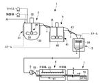
- the acrylic rubber veil can be suitably produced by the production method of the present invention including the following steps (1) to (5). That is, (1) An emulsion polymerization step in which a monomer component containing (meth) acrylic acid ester as a main component is emulsified with water and an emulsifier and emulsion-polymerized in the presence of a polymerization catalyst to obtain an emulsion polymerization solution.
- the emulsion polymerization step of the above (1) in the method for producing an acrylic rubber veil of the present invention is characterized in that the above-mentioned monomer component is emulsified with water and an emulsifier and emulsion-polymerized in the presence of a polymerization catalyst to obtain an emulsion polymerization solution. And.
- the emulsifier used in the emulsion polymerization step is not limited, and examples thereof include an anionic emulsifier, a cationic emulsifier, and a nonionic emulsifier. Among these, anionic emulsifiers and nonionic emulsifiers are preferable, and anionic emulsifiers are particularly preferable.
- anionic emulsifier examples include fatty acid-based emulsifiers, sulfonic acid-based emulsifiers, sulfosuccinic acid-based emulsifiers, sulfuric acid-based emulsifiers, phosphoric acid-based emulsifiers, etc., and sulfuric acid-based emulsifiers are preferable.
- fatty acid-based emulsifiers examples include sodium octanate, sodium decanoate, sodium laurate, sodium myristate, sodium palmitate, sodium stearate, and the like.
- sulfonic acid-based emulsifier examples include sodium hexane sulfonate, sodium octane sulfonate, sodium decane sulfonate, sodium toluene sulfonate, sodium cumene sulfonate, sodium octylbenzene sulfonate, sodium dodecylbenzene sulfonate, and dodecylbenzene sulfonic acid.
- examples thereof include ammonium, sodium naphthalene sulfonate, sodium alkylnaphthalene sulfonate, sodium alkyldiphenyl ether disulfonate and the like.
- sulfosuccinic acid-based emulsifier examples include sodium dioctyl sulfosuccinate and sodium dihexyl sulfosuccinate.
- a sulfate ester salt can be preferably used as the sulfuric acid-based emulsifier.
- the sulfate ester salt include sodium lauryl sulfate, ammonium lauryl sulfate, sodium myristyl sulfate, sodium laureth sulfate, sodium polyoxyethylene alkyl sulfate, sodium polyoxyethylene alkylaryl sulfate, and the like, and sodium lauryl sulfate is particularly preferable.
- Examples of the phosphoric acid-based emulsifier include sodium lauryl phosphate, potassium lauryl phosphate, sodium polyoxyalkylene alkyl ether phosphoric acid ester, and the like.
- Examples of the cationic emulsifier include alkyltrimethylammonium chloride, dialkylammonium chloride, and benzylammonium chloride.
- nonionic emulsifier examples include polyoxyalkylene fatty acid esters such as polyoxyethylene stearic acid ester; polyoxyalkylene alkyl ethers such as polyoxyethylene dodecyl ether; polyoxyalkylene alkyl phenol ethers such as polyoxyethylene nonylphenyl ether; and poly.
- examples thereof include oxyethylene sorbitan alkyl ester, and polyoxyalkylene alkyl ether and polyoxyalkylene alkyl phenol ether are preferable, and polyoxyethylene alkyl ether and polyoxyethylene alkyl phenol ether are more preferable.
- Each of these emulsifiers can be used alone or in combination of two or more, and the amount used is usually 0.01 to 10 parts by weight, preferably 0.1 to 10 parts by weight, based on 100 parts by weight of the monomer component. It is in the range of 5 parts by weight, more preferably 1 to 3 parts by weight.
- a conventional method may be followed, and examples thereof include a method of stirring the monomer, emulsifier and water using a stirrer such as a homogenizer or a disk turbine. ..
- the amount of water used is usually in the range of 10 to 750 parts by weight, preferably 50 to 500 parts by weight, and more preferably 100 to 400 parts by weight with respect to 100 parts by weight of the monomer component.
- the polymerization catalyst used in the emulsion polymerization step is not limited as long as it is usually used in emulsion polymerization, but for example, a redox catalyst composed of a radical generator and a reducing agent can be used.
- radical generator examples include peroxides and azo compounds, and peroxides are preferable.
- peroxide an inorganic peroxide or an organic peroxide is used.
- Examples of the inorganic peroxide include sodium persulfate, potassium persulfate, hydrogen peroxide, ammonium persulfate, etc.
- potassium persulfate, hydrogen peroxide, ammonium persulfate are preferable, and potassium persulfate is preferable. Especially preferable.
- organic peroxide examples include 2,2-di (4,4-di- (t-butylperoxy) cyclohexyl) propane, 1-di- (t-hexylperoxy) cyclohexane, and 1,1. -Di- (t-butylperoxy) cyclohexane, 4,4-di- (t-butylperoxy) n-butyl valerate, 2,2-di- (t-butylperoxy) butane, t-butylhydro Peroxide, cumene hydroperoxide, diisopropylbenzene hydroperoxide, paramentan hydroperoxide, benzoyl peroxide, 1,1,3,3-tetraethylbutylhydroperoxide, t-butylcumyl peroxide, di-t-butyl Peroxide, di-t-hexyl peroxide, di (2-t-butylperoxyisopropyl) benzene
- azo compound examples include azobisisobutyronitrile, 4,4'-azobis (4-cyanovaleric acid), 2,2'-azobis [2- (2-imidazolin-2-yl) propane, 2, 2'-azobis (propane-2-carboamidine), 2,2'-azobis [N- (2-carboxyethyl) -2-methylpropaneamide], 2,2'-azobis ⁇ 2- [1- (2) -Hydroxyethyl) -2-imidazolin-2-yl] propane ⁇ , 2,2'-azobis (1-imino-1-pyrrolidino-2-methylpropane) and 2,2'-azobis ⁇ 2-methyl-N- [1,1-bis (hydroxymethyl) -2-hydroxyethyl] propanamide ⁇ and the like can be mentioned.
- radical generators can be used individually or in combination of two or more, and the amount used is usually 0.0001 to 5 parts by weight, preferably 0.% by weight, based on 100 parts by weight of the monomer component. It is in the range of 0005 to 1 part by weight, more preferably 0.001 to 0.5 parts by weight.
- the reducing agent is not limited as long as it is used in the redox catalyst of emulsion polymerization, but in the present invention, it is particularly preferable to use at least two kinds of reducing agents in combination.
- the at least two types of reducing agents for example, a combination of a metal ion compound in a reduced state and another reducing agent is suitable.
- the metal ion compound in the reduced state is not particularly limited, and examples thereof include ferrous sulfate, sodium hexamethylenediamine tetraacetate, and cuprous naphthenate, and among these, ferrous sulfate is preferable.
- These reduced metal ion compounds can be used alone or in combination of two or more, and the amount used is usually 0.000001 to 0.01 weight by weight based on 100 parts by weight of the monomer component. Parts, preferably in the range of 0.00001 to 0.001 parts by weight, more preferably in the range of 0.00005 to 0.0005 parts by weight.
- the reducing agent other than the metal ion compound in the reduced state is not particularly limited, but is, for example, ascorbic acid such as ascorbic acid, sodium ascorbate, potassium ascorbate or a salt thereof; erythorbic acid, sodium erythorbicate, erythorbic acid.
- Elysorbic acid such as potassium or a salt thereof; sulphinate such as sodium hydroxymethane sulfite; sodium sulfite, potassium sulfite, sodium hydrogen sulfite, aldehyde sodium hydrogen sulfite, potassium hydrogen sulfite sulfite; sodium pyrosulfite, potassium pyrosulfite, Pyro sulfites such as sodium pyrosulfite and potassium hydrogen sulfite; thiosulfates such as sodium thiosulfite and potassium thiosulfite; subphosphates, sodium bisulfite, potassium bisulfite, sodium hydrogen phosphite, potassium hydrogen phosphite Phosphoric acid or a salt thereof; pyrophosylic acid such as pyrophosphate, sodium pyrophosphate, potassium pyrophosphate, sodium hydrogen pyrophosphate, potassium hydrogen pyrophosphate or a salt thereof; sodium formaldehyde
- the reducing agents other than the metal ion compounds in the reduced state can be used individually or in combination of two or more, and the amount used is usually 0.001 to 0.001 to 100 parts by weight of the monomer component. It is in the range of 1 part by weight, preferably 0.005 to 0.5 parts by weight, and more preferably 0.01 to 0.3 parts by weight.
- a preferable combination of the metal ion compound in the reduced state and the other reducing agent is a combination of ferrous sulfate and ascorbic acid or a salt thereof and / or sodium formaldehyde sulfoxylate, and more preferably ferrous sulfate. And ascorbate and / or sodium formaldehyde sulfoxylate, most preferably ferrous sulfate and alcorbate.
- the amount of ferrous sulfate used at this time is usually 0.000001 to 0.01 parts by weight, preferably 0.00001 to 0.001 parts by weight, and more preferably 0, based on 100 parts by weight of the monomer component.
- the amount of ascorbic acid or a salt thereof and / or sodium formaldehyde sulfoxylate used is usually 0.001 to 1 part by weight, preferably 0.001 to 1 part by weight, based on 100 parts by weight of the monomer component. Is in the range of 0.005 to 0.5 parts by weight, more preferably 0.01 to 0.3 parts by weight.
- the amount of water used in the emulsion polymerization reaction may be only the amount used at the time of emulsification of the monomer component, but is usually 10 to 1,000 parts by weight, preferably 10 to 1,000 parts by weight, based on 100 parts by weight of the monomer component used for polymerization. Is adjusted to be in the range of 50 to 500 parts by weight, more preferably 80 to 400 parts by weight, and most preferably 100 to 300 parts by weight.
- the method of the emulsion polymerization reaction may be a conventional method, and may be a batch type, a semi-batch type, or a continuous type.
- the polymerization temperature and the polymerization time are not particularly limited and can be appropriately selected depending on the type of polymerization initiator used and the like.
- the polymerization temperature is usually in the range of 0 to 100 ° C., preferably 5 to 80 ° C., more preferably 10 to 50 ° C., and the polymerization time is usually 0.5 to 100 hours, preferably 1 to 10 hours.
- the polymerization conversion rate of the emulsion polymerization reaction is not particularly limited, but when it is usually 80% by weight or more, preferably 90% by weight or more, and more preferably 95% by weight or more, the acrylic rubber bale produced is excellent in strength characteristics. Moreover, it is suitable because it has no monomeric odor.
- a polymerization inhibitor may be used to terminate the polymerization.
- the emulsion polymerization solution obtained in the emulsion polymerization step of the above (1) is brought into contact with a coagulation liquid consisting of a coagulant-containing aqueous solution to cause a hydrous crumb.
- a coagulation liquid consisting of a coagulant-containing aqueous solution to cause a hydrous crumb.
- the solid content concentration of the emulsion polymerization solution used in the coagulation step is not limited, but is usually adjusted to the range of 5 to 50% by weight, preferably 10 to 45% by weight, and more preferably 20 to 40% by weight.
- the coagulant used in the coagulation step is not particularly limited, but usually a metal salt is used.
- the metal salt include alkali metals, Group 2 metal salts of the Periodic Table, and other metal salts, preferably alkali metal salts, Group 2 metal salts of the Periodic Table, and more preferably alkali metal salts.
- alkali metal salt examples include sodium salts such as sodium chloride, sodium nitrate and sodium sulfate; potassium salts such as potassium chloride, potassium nitrate and potassium sulfate; and lithium salts such as lithium chloride, lithium nitrate and lithium sulfate.
- sodium salts such as sodium chloride and sodium sulfate are preferable, and sodium sulfate is particularly preferable.
- Examples of the Group 2 metal salt in the periodic table include magnesium chloride, calcium chloride, magnesium nitrate, calcium nitrate, magnesium sulfate, calcium sulfate and the like, and calcium chloride and magnesium sulfate are preferable.
- metal salts used as coagulants include, for example, zinc chloride, titanium chloride, manganese chloride, iron chloride, cobalt chloride, nickel chloride, aluminum chloride, tin chloride, zinc nitrate, titanium nitrate, manganese nitrate, iron nitrate. , Cobalt nitrate, nickel nitrate, aluminum nitrate, tin nitrate, zinc sulfate, titanium sulfate, manganese sulfate, iron sulfate, cobalt sulfate, nickel sulfate, aluminum sulfate, tin sulfate and the like.
- Each of these coagulants can be used alone or in combination of two or more, and the amount used is usually 0.01 to 100 parts by weight, preferably 0.1 to 100 parts by weight, based on 100 parts by weight of the monomer component. It is in the range of 50 parts by weight, more preferably 1 to 30 parts by weight. When the amount of the coagulant is in this range, it is preferable because it is possible to highly improve the compression set resistance and water resistance when the acrylic rubber veil is crosslinked while making the acrylic rubber solidify sufficiently. is there.
- the coagulant concentration of the coagulant used is usually 0.1 to 20% by weight, preferably 0.5 to 15% by weight, more preferably 1 to 10% by weight, and particularly preferably 1.5 to 1% by weight. It is preferable that the particle size of the hydrous crumb generated when it is in the range of 5% by weight can be uniformly focused in a specific region.
- the temperature of the coagulating liquid is not limited, but is preferably 40 ° C. or higher, preferably 40 to 90 ° C., more preferably 50 to 80 ° C., to produce a uniform hydrous crumb.
- the contact method between the emulsion polymerization solution and the coagulation solution is not limited, and for example, a method of adding the emulsion polymerization solution to the agitated coagulation solution and a method of adding the coagulation solution to the agitated emulsion polymerization solution. Either method may be used, but in the production method of the present invention, the method of adding the emulsion polymerization solution to the agitated coagulating liquid uniformly and focuses the shape and clam diameter of the water-containing crumb to be produced, and cleans the emulsifier and coagulant. It is suitable because the efficiency can be significantly improved.
- the rotation speed (stirring speed) of the coagulated liquid being agitated is represented by the rotation speed of the stirring blade of the stirring device provided in the coagulation bath, and is usually 100 rpm or more, preferably 200 to 1,000 rpm, more preferably 300 to 300. A range of 900 rpm, particularly preferably 400 to 800 rpm, is suitable.
- the rotation speed of the coagulation liquid is the rotation speed at which the coagulation liquid is vigorously agitated to some extent because the particle size of the water-containing crumbs produced can be made small and uniform.
- the peripheral speed of the coagulated liquid being agitated is represented by the linear velocity of the outer periphery of the stirring blade of the stirrer provided in the coagulation bath, and the water-containing crumb particle size generated when the coagulated liquid is vigorously agitated to a certain degree. Is preferable because it can be made small and uniform, and is usually 0.5 m / s or more, preferably 1 m / s or more, more preferably 1.5 m / s or more, particularly preferably 2 m / s or more, and most preferably 2.5 m / s. That is all.
- the upper limit of the peripheral speed is not limited, but the control of the coagulation reaction is usually performed when it is usually 50 m / s or less, preferably 30 m / s or less, more preferably 25 m / s or less, and most preferably 20 m / s or less. It is easy and suitable.
- the hydrous crumbs thus produced are suitable because they can satisfy all of the following conditions (a) to (e) when they are sieved by a JIS classification sieve.
- the JIS sieve complies with the provisions of Japanese Industrial Standards (JIS Z 8801-1).
- JIS Z 8801-1 The proportion of hydrous crumbs that do not pass through a JIS sieve with an opening of 9.5 mm is 10% by weight or less.
- B The proportion of hydrous crumbs that pass through a 9.5 mm mesh JIS sieve and do not pass through a 6.7 mm JIS sieve is 30% by weight or less.
- the proportion of relatively large hydrous crumbs that do not pass through the JIS sieve with an opening of 9.5 mm is 10% by weight or less, preferably 5% by weight or less, more preferably. Is 1% by weight or less
- the proportion of hydrous crumbs that pass through a 9.5 mm mesh JIS sieve but not a 6.7 mm JIS sieve is 30% by weight or less, preferably 20% by weight or less.
- the proportion of the hydrous crumb that passes through the JIS sieve having an opening of 6.7 mm but does not pass through the JIS sieve having a mesh size of 710 ⁇ m is 20% by weight or more, preferably 40% by weight or more. More preferably 70% by weight or more, most preferably 80% by weight or more, and (d) the proportion of hydrous crumb that passes through the JIS sieve having a mesh size of 710 ⁇ m but does not pass through the JIS sieve having a mesh size of 425 ⁇ m is 30% by weight or less, preferably 30% by weight or less.
- the proportion of relatively minute hydrous crumbs passing through a JIS sieve having an opening of 425 ⁇ m is 10% by weight or less, preferably 5% by weight.
- the cleaning efficiency of the emulsifier and the coagulant is remarkably improved, and the productivity is also increased, which is preferable.
- the proportion of the produced total hydrous crumb (f) that passes through the JIS sieve with an opening of 6.7 mm and does not pass through the JIS sieve with an opening of 4.75 mm is usually 40% by weight.
- it is preferably 10% by weight or less, more preferably 5% by weight or less, the cleaning efficiency of the emulsifier or coagulant is improved, which is preferable.
- the proportion of the produced total hydrous crumb that passes through the (g) JIS sieve with a mesh size of 4.75 mm and does not pass through the JIS sieve with a mesh size of 710 ⁇ m is usually 40% by weight or more.
- it is preferably 60% by weight or more, more preferably 80% by weight or more, the removal efficiency of the emulsifier and coagulant during cleaning and dehydration is remarkably improved, which is preferable.
- the proportion of the water-containing crumbs produced which (h) pass through the JIS sieve having a mesh size of 3.35 mm and do not pass through the JIS sieve having a mesh size of 710 ⁇ m is usually 20% by weight or more.
- it is preferably 40% by weight or more, more preferably 50% by weight or more, particularly preferably 60% by weight or more, and most preferably 70% by weight or more, the removal efficiency of the emulsifier and coagulant during washing and dehydration is remarkably high. It is suitable for improvement.
- the cleaning step (3) in the method for producing an acrylic rubber veil of the present invention is a step of cleaning the hydrous crumb produced in the solidification step (2).
- the cleaning method is not limited to the conventional method, and for example, the produced hydrous crumb can be mixed with a large amount of water.
- the amount of water used for washing is not particularly limited, but the amount per washing with water is usually 50 parts by weight or more, preferably 50 to 15,000 parts by weight, based on 100 parts by weight of the above-mentioned monomer component. It is preferable that the amount of ash in the acrylic rubber veil can be effectively reduced when the range is more preferably 100 to 10,000 parts by weight, particularly preferably 150 to 5,000 parts by weight.
- the temperature of the water used for cleaning is not limited, but it is suitable because the cleaning efficiency is improved when hot water is used as the cleaning water.
- the temperature of the hot water is not limited, but is preferably 40 ° C. or higher, preferably 40 to 100 ° C., more preferably 50 to 90 ° C., and most preferably 60 to 80 ° C., because the cleaning efficiency can be significantly increased. is there.
- the washing time is not limited, but is usually 1 to 120 minutes, preferably 2 to 60 minutes, and more preferably 3 to 30 minutes.
- the number of times of washing with water is not particularly limited, and is usually 1 to 10 times, preferably a plurality of times, and more preferably 2 to 3 times. From the viewpoint of reducing the residual amount of the coagulant in the finally obtained acrylic rubber veil, it is desirable that the number of washings with water is large, but the shape of the water-containing crumb and the diameter of the water-containing crumb should be specified. / Or the number of cleanings can be significantly reduced by setting the cleaning temperature within the above range.
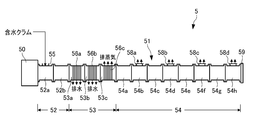
- the water-containing crumb washed in the washing step of the above (3) is combined with a dehydration barrel having a dehydration slit and a drying barrel under reduced pressure. It is characterized by dehydrating to a water content of 1 to 40% by weight in a dehydration barrel using a screw type extruder having a die at the tip, and then drying to less than 1% by weight in a drying barrel to extrude sheet-shaped dried rubber from the die. And.
- the water-containing crumb supplied to the screw type extruder is preferably one in which free water is removed (drained) after washing.
- Draining step In the method for producing an acrylic rubber bale of the present invention, free water is separated from the water-containing crumb after washing by a drainer after the washing (washing) step of (3) above and before the dehydration / drying step described later. It is preferable to provide a draining step to improve the dehydration efficiency.
- the drainer a known one can be used without particular limitation, and examples thereof include a wire mesh, a screen, an electric sieve, and the like, preferably a wire mesh and a screen.
- the opening of the drainer is not limited, but when it is usually in the range of 0.01 to 5 mm, preferably 0.1 to 1 mm, more preferably 0.2 to 0.6 mm, the water content crumb loss is small and It is suitable because it can drain water efficiently.
- the water content of the water-containing crumb after draining that is, the water content of the water-containing crumb added to the dehydration / drying step is not limited, but is usually 50 to 80% by weight, preferably 50 to 70% by weight, and more preferably 50 to 60% by weight. It is in the range of% by weight.
- the temperature of the water-containing crumb after draining that is, the temperature of the water-containing crumb put into the dehydration / drying step is not limited, but is usually 40 ° C. or higher, preferably 40 to 100 ° C., more preferably 50 to 90 ° C., particularly preferably.
- the temperature is in the range of 55 to 85 ° C, most preferably 60 to 80 ° C, a water-containing crumb having a high specific heat of 1.5 to 2.5 KJ / kg ⁇ K and difficult to raise the temperature like the acrylic rubber of the present invention is screw type.
- dehydrating and drying using an extruder it is suitable because it can be efficiently dehydrated and dried.
- Dehydration of hydrous crumbs Dehydration barrel
- Dehydration of the water-containing crumb is performed in a dehydration barrel having a dehydration slit provided in the screw type extruder.
- the opening of the dehydration slit may be appropriately selected according to the conditions of use, but is usually in the range of 0.01 to 5 mm, preferably 0.1 to 1 mm, and more preferably 0.2 to 0.6 mm.
- the number of dehydration barrels in the screw type extruder is not limited, but it is usually possible to efficiently dehydrate the adhesive acrylic rubber when the number is usually a plurality, preferably 2 to 10, more preferably 3 to 6. It is suitable because it can be done.
- the set temperature of the dehydration barrel is appropriately selected depending on the monomer composition of the acrylic rubber, the ash content, the water content of the crumb, the operating conditions, and the like, but is usually 60 to 150 ° C., preferably 70 to 140 ° C., more preferably 80. It is in the range of ⁇ 130 ° C.
- the set temperature of the drainage type dehydration barrel that dehydrates in the drainage state is usually 60 ° C. to 120 ° C., preferably 70 to 110 ° C., and more preferably 80 to 100 ° C.
- the set temperature of the exhaust steam type dehydration barrel that dehydrates in the exhaust steam state is usually in the range of 100 to 150 ° C., preferably 105 to 140 ° C., and more preferably 110 to 130 ° C.
- the water content after dehydration in the drainage type dehydration barrel that squeezes water from the water content crumb is not limited, but is usually 1 to 40% by weight, preferably 5 to 40% by weight, more preferably 5 to 35% by weight, and particularly preferably. When it is 10 to 35% by weight, most preferably 15 to 35% by weight, the productivity and the efficiency of ash removal are highly balanced and preferable.
- the acrylic rubber adheres to the dehydration slit portion and can hardly be dehydrated, and the water content is up to about 45 to 55% by weight. Only reduces.
- the water content can be reduced to the above range.
- the water content after dehydration in the drain type dehydration barrel portion is usually 5 to 40% by weight, preferably 10 to 35% by weight, more preferably. Is 15 to 35% by weight, and the water content after pre-drying in the exhaust steam type dehydration barrel portion is usually 1 to 30% by weight, preferably 3 to 20% by weight, and more preferably 5 to 15% by weight.
- the water content of the crumb after the dehydration step is 1 to 40% by weight as described above, but the dehydration time is shortened by setting the water content at this stage to the above lower limit or more. As a result, deterioration of acrylic rubber can be suppressed, and the amount of ash can be sufficiently reduced by setting the content to the above upper limit or less.
- Drying of hydrous crumb (dry barrel)
- the hydrous crumb after dehydration is dried in a drying barrel portion under reduced pressure provided on the downstream side (closer to the die) of the dehydration barrel of the screw type extruder.
- the degree of decompression of the drying barrel may be appropriately selected, but is preferably 1 to 50 kPa, preferably 2 to 30 kPa, more preferably 3 to 20 kPa, because the hydrous crumb can be efficiently dried.
- the set temperature of the drying barrel may be appropriately selected, but when it is usually in the range of 100 to 250 ° C., preferably 110 to 200 ° C., more preferably 120 to 180 ° C., there is no discoloration or deterioration of the acrylic rubber. It is suitable because it can be dried efficiently and the amount of gel in which the methyl ethyl ketone is insoluble in acrylic rubber can be reduced.
- the number of drying barrels in the screw type extruder is not limited, but is usually a plurality, preferably 2 to 10, and more preferably 3 to 8.
- the decompression degree may be an approximate decompression degree for all the dry barrels, or may be a different decompression degree.
- the set temperature may be changed to an approximate temperature for all the drying barrels, but the temperature of the clam introduction part (closer to the dehydration barrel) is higher than the temperature of the discharge part (on the die). It is preferable that the temperature of (closer) is higher because the drying efficiency can be increased.
- the water content of the dried rubber after drying is usually less than 1% by weight, preferably 0.8% by weight or less, and more preferably 0.6% by weight or less.
- the gel amount of the methyl ethyl ketone insoluble portion of the acrylic rubber veil can be reduced by melt-extruding the dry rubber with the water content set to this value (in a state where most of the water is removed), particularly in the screw type extruder. Suitable.
- Acrylic rubber shape (die part)
- the acrylic rubber dehydrated and dried by the screw portion of the dehydration barrel and the drying barrel is sent to the rectifying die portion without a screw.
- a breaker plate or wire mesh may or may not be provided between the screw portion and the die portion.
- the dry rubber extruded from the die portion of the screw type extruder is suitable because the die shape is made substantially rectangular and the die is formed into a sheet shape, so that air is less likely to be entrained and a dry rubber having a large specific gravity and excellent storage stability can be obtained. ..
- the resin pressure in the die portion is not particularly limited, but when it is usually in the range of 0.1 to 10 MPa, preferably 0.5 to 5 MPa, and more preferably 1 to 3 MPa, less air entrainment (high specific gravity). Moreover, it is excellent in productivity and suitable.
- Screw type extruder and operating conditions The screw length (L) of the screw type extruder used may be appropriately selected according to the purpose of use, but is usually 3,000 to 15,000 mm, preferably 4,000 to. It is in the range of 10,000 mm, more preferably 4,500 to 8,000 mm.
- the screw diameter (D) of the screw type extruder may be appropriately selected depending on the intended use, but is usually in the range of 50 to 250 mm, preferably 100 to 200 mm, and more preferably 120 to 160 mm.
- the ratio (L / D) of the screw length (L) to the screw diameter (D) of the screw type extruder is not limited, but is usually 10 to 100, preferably 20 to 80, more preferably 30 to 60, and particularly preferably. Is suitable because the water content can be reduced to less than 1% by weight without lowering the molecular weight of the dried rubber or causing discoloration when the value is in the range of 40 to 50.
- the rotation speed (N) of the screw type extruder may be appropriately selected according to various conditions, but is usually 10 to 1,000 rpm, preferably 50 to 750 rpm, more preferably 100 to 500 rpm, and most preferably. When the speed is 120 to 300 rpm, the water content of the acrylic rubber and the gel amount of the insoluble methyl ethyl ketone can be efficiently reduced, which is preferable.
- the extrusion amount (Q) of the screw type extruder is not limited, but is usually 100 to 1,500 kg / hr, preferably 300 to 1,200 kg / hr, more preferably 400 to 1,000 kg / hr, and most preferably. It is in the range of 500 to 800 kg / hr.
- the ratio (Q / N) of the extrusion amount (Q) to the rotation speed (N) of the screw type extruder is also not limited, but is usually in the range of 2 to 10, preferably 3 to 8, and more preferably 4 to 6.
- the quality including the strength characteristics of the acrylic rubber veil that is sometimes obtained and the productivity of manufacturing are highly balanced and suitable.
- Sheet-shaped dry rubber The shape of the dry rubber extruded from the screw-type extruder by the manufacturing method of the present invention is sheet-like. In this case, the specific gravity can be increased without entraining air during extrusion, and the storage stability is highly improved. Therefore, it is suitable.
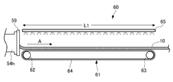
- the sheet-shaped dry rubber extruded from the screw type extruder in this way is usually cooled and cut to be used as an acrylic rubber sheet.
- the thickness of the sheet-shaped dry rubber extruded from the screw type extruder is not particularly limited, but is usually in the range of 1 to 40 mm, preferably 2 to 35 mm, more preferably 3 to 30 mm, and most preferably 5 to 25 mm. It is suitable because it has excellent workability and productivity at some time. In particular, since the thermal conductivity of the sheet-shaped dry rubber is as low as 0.15 to 0.35 W / mK, the thickness of the sheet-shaped dry rubber is usually 1 to 30 mm when the cooling efficiency is increased and the productivity is remarkably improved.
- the range is preferably 2 to 25 mm, more preferably 3 to 15 mm, and particularly preferably 4 to 12 mm.
- the width of the sheet-shaped dry rubber extruded from the screw type extruder is appropriately selected according to the purpose of use, but is usually in the range of 300 to 1,200 mm, preferably 400 to 1,000 mm, and more preferably 500 to 800 mm. is there.
- the temperature of the dry rubber extruded from the screw type extruder is not limited, but is usually in the range of 100 to 200 ° C, preferably 110 to 180 ° C, and more preferably 120 to 160 ° C.
- the water content of the dry rubber extruded from the screw type extruder is usually less than 1% by weight, preferably 0.8% by weight or less, and more preferably 0.6% by weight or less.
- the complex viscosity ([ ⁇ ] 100 ° C.) of the sheet-shaped dry rubber extruded from the screw type extruder at 100 ° C. is not limited, but is usually 1,500 to 6,000 Pa ⁇ s, preferably 2,000 to 5, When the range is 000 Pa ⁇ s, more preferably 2,500 to 4,000 Pa ⁇ s, and most preferably 2,500 to 3,500 Pa ⁇ s, the extrudability as a sheet and the shape retention are highly balanced. Is suitable.
- the extrudability can be improved, and by setting it to the above upper limit or less, the shape of the sheet-shaped dried rubber can be suppressed from collapsing or breaking. ..
- the sheet-shaped dry rubber extruded from the screw type extruder is laminated and veiled after cutting because the amount of air entrained is small and the storage stability is excellent.
- the cutting method of the sheet-shaped dry rubber is not limited, but since the acrylic rubber of the acrylic rubber veil of the present invention has strong adhesiveness, the sheet-shaped dry rubber is cooled in order to continuously cut without entraining air. It is preferable to do this afterwards.
- the cutting temperature of the sheet-shaped dry rubber is not limited, but is preferably 60 ° C. or lower, preferably 55 ° C. or lower, more preferably 50 ° C. or lower, with a high balance between cutability and productivity.
- the complex viscosity ([ ⁇ ] 60 ° C.) of the sheet-shaped dry rubber at 60 ° C. is not limited, but is usually 15,000 Pa ⁇ s or less, preferably 2,000 to 10,000 Pa ⁇ s, more preferably 2,500. When it is in the range of about 7,000 Pa ⁇ s, most preferably 2,700 to 5,500 Pa ⁇ s, it is preferable that it can be cut continuously without entraining air.
- the ratio ([ ⁇ ] 100 ° C./[ ⁇ ] 60 ° C.) of the complex viscosity at 100 ° C. ([ ⁇ ] 100 ° C.) of the sheet-shaped dried rubber to the complex viscosity ([ ⁇ ] 60 ° C.) at 60 ° C. is Of the air, but not limited, usually in the range of 0.5 or more, preferably 0.5 to 0.98, more preferably 0.6 to 0.95, most preferably 0.75 to 0.93. It is suitable because there is little entrainment and the cutting and productivity are highly balanced.
- the cooling method of the sheet-shaped dry rubber may be left at room temperature without limitation and allowed to cool. However, since the thermal conductivity of the sheet-shaped dry rubber is very small, 0.15 to 0.35 W / mK, it is blown or blown. Forced cooling such as an air cooling method under cooling, a water spraying method in which water is sprayed, or an immersion method in which water is immersed is preferable in order to increase productivity, and an air cooling method in which air is blown or cooled is particularly preferable.
- the sheet-shaped dry rubber can be extruded from a screw-type extruder onto a conveyor such as a belt conveyor, and can be conveyed and cooled while blowing cold air.
- the temperature of the cold air is not limited, but is usually in the range of 0 to 25 ° C, preferably 5 to 25 ° C, and more preferably 10 to 20 ° C.
- the length to be cooled is not particularly limited, but is usually in the range of 5 to 500 m, preferably 10 to 200 m, and more preferably 20 to 100 m.
- the cooling rate of the sheet-shaped dry rubber is not limited, but is preferably 50 ° C./hr or higher, more preferably 100 ° C./hr or higher, and more preferably 150 ° C./hr or higher because cutting is particularly easy. ..
- the cutting length of the sheet-shaped dry rubber is not limited and may be appropriately selected according to the size of the acrylic rubber veil to be manufactured, but is usually 100 to 800 mm, preferably 200 to 500 mm, more preferably 250 to 450 mm. The range.
- the bale step (5) in the method for producing an acrylic rubber veil of the present invention is, for example, bale by laminating and integrating sheet-shaped dry rubber.
- the laminating temperature of the sheet-shaped dry rubber is not limited, but is preferably 30 ° C. or higher, preferably 35 ° C. or higher, more preferably 40 ° C. or higher, because the air entrained during laminating can be released well.
- the number of laminated layers may be appropriately selected according to the size or weight of the acrylic rubber veil.
- the acrylic rubber veil of the present invention thus obtained has excellent operability and storage stability as compared with crumb-shaped acrylic rubber, and the acrylic rubber veil is put into a mixer such as a Banbury mixer or a roll as it is or after cutting a required amount. can do.
- the rubber mixture of the present invention is characterized in that the above acrylic rubber veil is mixed with a filler and a cross-linking agent.
- the filler used in the rubber mixture is not limited, and examples thereof include a reinforcing filler and a non-reinforcing filler, and a reinforcing filler is preferable.
- Examples of such a reinforcing filler include carbon black such as furnace black, acetylene black, thermal black, channel black, and graphite; silica such as wet silica, dry silica, and colloidal silica; and the like.
- the non-reinforcing filler includes quartz powder, silica soil, zinc oxide, basic magnesium carbonate, activated calcium carbonate, magnesium silicate, aluminum silicate, titanium dioxide, talc, aluminum sulfate, calcium sulfate, and barium sulfate. And so on.
- fillers can be used individually or in combination of two or more, and the blending amount thereof is not particularly limited, but the filler is usually 1 to 200 with respect to 100 parts by weight of the acrylic rubber veil. It is in the range of 10 to 150 parts by weight, more preferably 20 to 100 parts by weight.
- the cross-linking agent used in the rubber mixture may be appropriately selected according to the type and application of the reactive group contained in the acrylic rubber constituting the acrylic rubber bale, but is exceptional as long as it can cross-link the acrylic rubber bale.
- polyvalent amine compounds such as diamine compounds and carbonates thereof; sulfur compounds; sulfur donors; triazinethiol compounds; polyvalent epoxy compounds; ammonium organic carboxylates; organic peroxides; polyvalent carboxylics.
- Conventionally known cross-linking agents such as acids; quaternary onium salts; imidazole compounds; isocyanuric acid compounds; organic peroxides; triazine compounds; can be used.
- polyvalent amine compounds ammonium carboxylates, metal dithiocarbamic acid salts and triazinethiol compounds are preferable, hexamethylenediamine carbamate, 2,2'-bis [4- (4-aminophenoxy) phenyl] propane, and benzoate.
- Ammonium acid, 2,4,6-trimercapto-1,3,5-triazine is particularly preferred.
- the acrylic rubber veil to be used is composed of a carboxyl group-containing acrylic rubber
- a polyvalent amine compound and a carbonate thereof as a cross-linking agent.
- the polyvalent amine compound include aliphatic polyvalent amine compounds such as hexamethylenediamine, hexamethylenediamine carbamate, and N, N'-dicinnamylidene-1,6-hexanediamine; 4,4'-methylenedianiline, p.
- acrylic rubber veil to be used is composed of epoxy group-containing acrylic rubber
- aliphatic polyvalent amine compounds such as hexamethylenediamine and hexamethylenediamine carbamate and their carbonates are used as cross-linking agents; 4,4'-methylenedi.
- Aromatic polyvalent amine compounds such as aniline; ammonium carboxylic acids such as ammonium benzoate and ammonium adipate; metal dithiocarbamic acids such as zinc dimethyldithiocarbamate; polyvalent carboxylic acids such as tetradecanodic acid; cetyltrimethylammonium bromide and the like
- a quaternary onium salt an imidazole compound such as 2-methylimidazole; an isocyanuric acid compound such as ammonium isocyanurate; and the like can be used.
- ammonium carboxylic acid salt and metal dithiocarbamate salt are preferable, and ammonium benzoate is preferable. More preferable.
- the acrylic rubber veil to be used is composed of halogen atom-containing acrylic rubber
- sulfur it is preferable to use sulfur, a sulfur donor, or a triazine thiol compound as a cross-linking agent.
- sulfur donor include dipentamethylene thiuram hexasulfide and triethyl thiuram disulfide.
- triazine compound examples include 6-trimercapto-s-triazine, 2-anilino-4,6-dithiol-s-triazine, 1-dibutylamino-3,5-dimercaptotriazine, 2-dibutylamino-4, 6-Dithiol-s-Triazine, 1-Phenylamino-3,5-Dimercaptotriazine, 2,4,6-Trimercapto-1,3,5-Triazine, 1-Hexylamino-3,5-Dimercaptotriazine Among these, 2,4,6-trimercapto-1,3,5-triazine is preferable.
- cross-linking agents can be used alone or in combination of two or more, and the blending amount thereof is usually 0.001 to 20 parts by weight, preferably 0.1 to 10 parts by weight, based on 100 parts by weight of the acrylic rubber veil. It is by weight, more preferably 0.1 to 5 parts by weight.
- the blending amount of the cross-linking agent is usually 0.001 to 20 parts by weight, preferably 0.1 to 10 parts by weight, based on 100 parts by weight of the acrylic rubber veil. It is by weight, more preferably 0.1 to 5 parts by weight.
- rubber mixture of the present invention in addition to the above acrylic rubber veil, other rubber components can be blended as a rubber component, if necessary.
- the other rubber components to be blended as needed are not particularly limited, and for example, natural rubber, polybutadiene rubber, polyisoprene rubber, styrene-butadiene rubber, acrylonitrile-butadiene rubber, silicon rubber, fluororubber, and olefin elastomer. , Styrene-based elastomer, vinyl chloride-based elastomer, polyester-based elastomer, polyamide-based elastomer, polyurethane-based elastomer, polysiloxane-based elastomer and the like.
- the shape of the other rubber component is not limited, and may be, for example, a powder or granular material, a crumb, a sheet, a veil, or the like.
- These other rubber components can be used alone or in combination of two or more.
- the amount of these other rubber components used is appropriately selected within a range that does not impair the effects of the present invention.
- the rubber mixture of the present invention can be blended with an anti-aging agent as needed.
- the anti-aging agent is not particularly limited, but is 2,6-di-t-butyl-4-methylphenol, 2,6-di-t-butylphenol, butylhydroxyaniline, 2,6-di-t-butyl-.
- anti-aging agents can be used individually or in combination of two or more, and the blending amount thereof is 0.01 to 15 parts by weight, preferably 0.1 to 100 parts by weight, based on 100 parts by weight of the acrylic rubber veil. It is in the range of 10 parts by weight, more preferably 1 to 5 parts by weight.
- the rubber mixture of the present invention contains the acrylic rubber veil of the present invention, a filler, a cross-linking agent and, if necessary, other rubber components and an anti-aging agent, and is usually used in the art as necessary.
- additional blending of other additives such as cross-linking aids, cross-linking accelerators, cross-linking retarders, silane coupling agents, plasticizers, processing aids, rubbers, pigments, colorants, antistatic agents, foaming agents, etc. it can.
- These other compounding agents can be used alone or in combination of two or more, and the amount of each compounding is appropriately selected within a range that does not impair the effects of the present invention.
- Examples of the method for producing a rubber mixture of the present invention include a method of mixing a filler, a cross-linking agent and other compounding agents which can be contained as needed in the acrylic rubber veil of the present invention. Any means conventionally used in the rubber processing field, such as an open roll, a Banbury mixer, and various kneaders, can be used. That is, using these mixers, the acrylic rubber veil can be mixed by directly mixing the filler, the cross-linking agent and the like, preferably by directly kneading.
- the acrylic rubber veil of the present invention may be used in the form of the obtained veil, or may be used after being divided (cut, etc.).
- each component is not limited, but for example, after sufficiently mixing the components that are difficult to react or decompose by heat, the cross-linking agent, which is a component that easily reacts or decomposes by heat, is mixed at a temperature at which the reaction or decomposition does not occur.
- Two-step mixing which mixes in a short time, is preferable. Specifically, it is preferable to mix the acrylic rubber veil and the filler in the first step and then mix the cross-linking agent in the second step.
- Other rubber components and anti-aging agents are usually mixed in the first stage, the cross-linking accelerator may be selected in the second stage, and other compounding agents may be appropriately selected.
- the Mooney viscosity (ML1 + 4,100 ° C.; compound Mooney) of the rubber mixture of the present invention is not limited, but is usually in the range of 10 to 150, preferably 20 to 100, and more preferably 25 to 80.
- the rubber crosslinked product of the present invention is obtained by cross-linking the above rubber mixture.
- the rubber crosslinked product of the present invention is formed by using the rubber mixture of the present invention with a molding machine corresponding to a desired shape, for example, an extruder, an injection molding machine, a compressor, a roll, etc., and then heated to carry out a cross-linking reaction. It can be manufactured by fixing the shape as a rubber crosslinked product.
- the cross-linking may be performed after molding in advance or at the same time as the molding.
- the molding temperature is usually 10 to 200 ° C, preferably 25 to 150 ° C.
- the crosslinking temperature is usually 100 to 250 ° C., preferably 130 to 220 ° C., more preferably 150 to 200 ° C.
- the crosslinking time is usually 0.1 minutes to 10 hours, preferably 1 minute to 5 hours.
- a method used for cross-linking rubber such as press heating, steam heating, oven heating and hot air heating may be appropriately selected.
- the rubber crosslinked product of the present invention may be further heated for secondary cross-linking depending on the shape, size, etc. of the rubber cross-linked product.
- the secondary cross-linking varies depending on the heating method, cross-linking temperature, shape and the like, but is preferably carried out for 1 to 48 hours.
- the heating method and heating temperature may be appropriately selected.
- the crosslinked rubber product of the present invention has excellent water resistance while maintaining basic characteristics as rubber such as tensile strength, elongation, and hardness.
- the rubber crosslinked product of the present invention makes use of the above-mentioned excellent characteristics, for example, O-ring, packing, diaphragm, oil seal, shaft seal, bearing sheath, mechanical seal, well head seal, seal for electric / electronic equipment, and the like.
- Sealing materials such as seals for air compression equipment; rocker cover gaskets attached to the connection between the cylinder block and the cylinder head, oil pan gaskets attached to the connection between the oil pan and the cylinder head or the transmission case, positive electrode, electrolyte.
- gaskets such as gaskets for fuel cell separators and gaskets for top covers of hard disk drives mounted between a pair of housings that sandwich a unit cell with a plate and a negative electrode; cushioning material, vibration isolator; wire coating material; industrial belt Classes; tubes, hoses; sheets; etc.
- the rubber crosslinked product of the present invention is also used as an extruded molded product and a mold crosslinked product for automobile applications, for example, a fuel oil system around a fuel tank such as a fuel hose, a filler neck hose, a vent hose, a paper hose, and an oil hose. It is suitably used for various hoses such as hoses, turbo air hoses, air hoses such as mission control hoses, radiator hoses, heater hoses, brake hoses, and air conditioner hoses.
- FIG. 1 is a diagram schematically showing an example of an acrylic rubber manufacturing system having an apparatus configuration used for manufacturing an acrylic rubber veil according to an embodiment of the present invention.
- the acrylic rubber production system 1 shown in FIG. 1 can be used.
- the acrylic rubber manufacturing system 1 shown in FIG. 1 is composed of an emulsion polymerization reactor (not shown), a coagulation device 3, a cleaning device 4, a drainer 43, a screw type extruder 5, a cooling device 6, and a bale device 7. ..
- the emulsion polymerization reactor is configured to perform the treatment related to the emulsion polymerization step described above.
- this emulsion polymerization reactor includes, for example, a polymerization reaction tank, a temperature control unit for controlling the reaction temperature, a motor, and a stirring device including a stirring blade.
- water and an emulsifier are mixed with a monomer component for forming acrylic rubber, emulsified while appropriately stirring with a stirrer, and emulsion polymerization is carried out in the presence of a polymerization catalyst to obtain an emulsion polymerization solution. Can be obtained.
- the emulsion polymerization reactor may be a batch type, a semi-batch type, or a continuous type, and may be any of a tank type reactor and a tube type reactor.
- the coagulation device 3 shown in FIG. 1 is configured to perform the process related to the coagulation step described above.
- the coagulation device 3 includes, for example, a stirring tank 30, a heating unit 31 for heating the inside of the stirring tank 30, and a temperature control unit (not shown) for controlling the temperature inside the stirring tank 30. It has a stirring device 34 including a motor 32 and a stirring blade 33, and a drive control unit (not shown) that controls the rotation speed and rotation speed of the stirring blade 33.
- a hydrous crumb can be produced by bringing the emulsion polymerization solution obtained by the emulsion polymerization reactor into contact with the coagulation solution as a coagulant and coagulating it.
- the contact between the emulsion polymerization solution and the coagulation solution adopts a method of adding the emulsion polymerization solution to the stirring coagulation solution. That is, a hydrous crumb is generated by filling the stirring tank 30 of the coagulation device 3 with a coagulation liquid and adding and contacting the emulsion polymerization liquid with the coagulation liquid to coagulate the emulsion polymerization liquid.
- the heating unit 31 of the coagulation device 3 is configured to heat the coagulation liquid filled in the stirring tank 30. Further, the temperature control unit of the coagulation device 3 controls the temperature inside the stirring tank 30 by controlling the heating operation by the heating unit 31 while monitoring the temperature inside the stirring tank 30 measured by the thermometer. It is configured. The temperature of the coagulating liquid in the stirring tank 30 is controlled by the temperature control unit so as to be usually in the range of 40 ° C. or higher, preferably 40 to 90 ° C., and more preferably 50 to 80 ° C.
- the stirring device 34 of the coagulating device 3 is configured to stir the coagulating liquid filled in the stirring tank 30.
- the stirring device 34 includes a motor 32 that generates rotational power and a stirring blade 33 that extends in a direction perpendicular to the rotation axis of the motor 32.
- the stirring blade 33 can flow the coagulating liquid by rotating around the rotation axis by the rotational power of the motor 32 in the coagulating liquid filled in the stirring tank 30.
- the shape and size of the stirring blade 33, the number of installations, and the like are not particularly limited.
- the drive control unit of the coagulation device 3 is configured to control the rotational drive of the motor 32 of the stirring device 34 to set the rotation speed and the rotation speed of the stirring blade 33 of the stirring device 34 to predetermined values.
- the rotation of the stirring blade 33 by the drive control unit so that the stirring number of the coagulating liquid is, for example, usually 100 rpm or more, preferably 200 to 1,000 rpm, more preferably 300 to 900 rpm, and particularly preferably 400 to 800 rpm. Is controlled.
- the peripheral speed of the coagulant is usually 0.5 m / s or more, preferably 1 m / s or more, more preferably 1.5 m / s or more, particularly preferably 2 m / s or more, and most preferably 2.5 m / s or more.
- the rotation of the stirring blade 33 is controlled by the drive control unit. Further, the drive control unit agitates the coagulant so that the upper limit of the peripheral speed is usually 50 m / s or less, preferably 30 m / s or less, more preferably 25 m / s or less, and most preferably 20 m / s or less.
- the rotation of the wing 33 is controlled.
- the cleaning device 4 shown in FIG. 1 is configured to perform the processing related to the cleaning process described above.
- the cleaning device 4 includes, for example, a cleaning tank 40, a heating unit 41 that heats the inside of the cleaning tank 40, and a temperature control unit (not shown) that controls the temperature inside the cleaning tank 40.
- a temperature control unit not shown
- the amount of ash in the finally obtained acrylic rubber veil can be effectively reduced by mixing the hydrous crumb generated by the coagulation device 3 with a large amount of water and cleaning.
- the heating unit 41 of the cleaning device 4 is configured to heat the inside of the cleaning tank 40. Further, the temperature control unit of the cleaning device 4 controls the temperature inside the cleaning tank 40 by controlling the heating operation by the heating unit 41 while monitoring the temperature inside the cleaning tank 40 measured by the thermometer. It is configured. As described above, the temperature of the washing water in the washing tank 40 is usually controlled to be in the range of 40 ° C. or higher, preferably 40 to 100 ° C., more preferably 50 to 90 ° C., and most preferably 60 to 80 ° C. To.
- the water-containing crumb washed by the washing device 4 is supplied to the screw type extruder 5 that performs the dehydration step and the drying step. At this time, it is preferable that the water-containing crumb after cleaning is supplied to the screw type extruder 5 through a drainer 43 capable of separating free water.
- a drainer 43 capable of separating free water.
- a wire mesh, a screen, an electric sieve, or the like can be used.
- the temperature of the water-containing crumb is preferably 40 ° C. or higher, more preferably 60 ° C. or higher.
- the temperature of the water-containing crumb when supplied to the screw type extruder 5 is maintained at 60 ° C. or higher.
- the temperature of the hydrous crumb may be 40 ° C. or higher, preferably 60 ° C. or higher when it is conveyed from the cleaning device 4 to the screw type extruder 5.
- the screw type extruder 5 shown in FIG. 1 is configured to perform the processes related to the above-mentioned dehydration step and drying step.
- a centrifuge, a squeezer, or the like may be used as the dehydrator for performing the treatment related to the dehydration step, and the treatment related to the drying step may be performed.
- a hot air dryer, a vacuum dryer, an expander dryer, a kneader type dryer, or the like may be used as the dryer.
- the screw type extruder 5 is configured to mold the dried rubber obtained through the dehydration step and the drying step into a predetermined shape and discharge it.
- the screw type extruder 5 has a dehydration barrel portion 53 having a function as a dehydrator for dehydrating the hydrous crumb washed by the cleaning device 4, and a dryer having a function as a dryer for drying the hydrous crumb.
- a barrel portion 54 is provided, and a die 59 having a molding function for forming a water-containing crumb is provided on the downstream side of the screw type extruder 5.
- FIG. 2 shows a configuration of a specific example suitable for the screw type extruder 5 shown in FIG.
- the above-mentioned dehydration / drying step can be suitably performed.
- the screw type extruder 5 shown in FIG. 2 is a twin-screw type extruder / dryer provided with a pair of screws (not shown) in the barrel unit 51.
- the screw type extruder 5 has a drive unit 50 that rotationally drives a pair of screws in the barrel unit 51.
- the drive unit 50 is attached to the upstream end (left end in FIG. 2) of the barrel unit 51.
- the screw type extruder 5 has a die 59 at the downstream end (right end in FIG. 2) of the barrel unit 51.
- the barrel unit 51 has a supply barrel portion 52, a dehydration barrel portion 53, and a dry barrel portion 54 from the upstream side to the downstream side (from the left side to the right side in FIG. 2).
- the supply barrel portion 52 is composed of two supply barrels, that is, a first supply barrel 52a and a second supply barrel 52b.
- the dehydration barrel portion 53 is composed of three dehydration barrels, that is, a first dehydration barrel 53a, a second dehydration barrel 53b, and a third dehydration barrel 53c.
- the drying barrel portion 54 includes eight drying barrels, that is, a first drying barrel 54a, a second drying barrel 54b, a third drying barrel 54c, a fourth drying barrel 54d, and a fifth drying barrel 54e. , A sixth dry barrel 54f, a seventh dry barrel 54g, and an eighth dry barrel 54h.
- the barrel unit 51 is configured by connecting 13 divided barrels 52a to 52b, 53a to 53c, 54a to 54h from the upstream side to the downstream side.
- the screw type extruder 5 individually heats the barrels 52a to 52b, 53a to 53c, 54a to 54h, and determines the water content crumbs in the barrels 52a to 52b, 53a to 53c, 54a to 54h, respectively. It has a heating means (not shown) for heating to a temperature.
- the heating means includes a number corresponding to each barrel 52a to 52b, 53a to 53c, 54a to 54h.
- a heating means for example, a configuration is adopted in which high-temperature steam is supplied from the steam supply means to the steam distribution jackets formed in the barrels 52a to 52b, 53a to 53c, 54a to 54h. It is not limited to this.
- the screw type extruder 5 has a temperature control means (not shown) that controls a set temperature of each heating means corresponding to each barrel 52a to 52b, 53a to 53c, 54a to 54h.
- the number of supply barrels, dehydration barrels, and drying barrels that constitute each barrel portion 52, 53, 54 in the barrel unit 51 is not limited to the mode shown in FIG. 2, and the acrylic rubber to be dried is used.
- the number can be set according to the water content of the water-containing crumb.
- the number of supply barrels installed in the supply barrel portion 52 is, for example, 1 to 3.
- the number of dehydration barrels installed in the dehydration barrel portion 53 is preferably, for example, 2 to 10, and more preferably 3 to 6, because dehydration of the water-containing crumb of the adhesive acrylic rubber can be efficiently performed.
- the number of dry barrels installed in the dry barrel portion 54 is preferably, for example, 2 to 10, and more preferably 3 to 8.
- the pair of screws in the barrel unit 51 are rotationally driven by a driving means such as a motor housed in the driving unit 50.
- the pair of screws extend from the upstream side to the downstream side in the barrel unit 51, and by being rotationally driven, the water-containing crumbs supplied to the supply barrel portion 52 can be conveyed to the downstream side while being mixed. It has become like.
- the pair of screws is preferably a biaxial meshing type in which the peaks and valleys are meshed with each other, whereby the dehydration efficiency and the drying efficiency of the hydrous crumb can be improved.
- the rotation direction of the pair of screws may be the same direction or different directions, but from the viewpoint of self-cleaning performance, a type that rotates in the same direction is preferable.
- the screw shape of the pair of screws is not particularly limited as long as it is a shape required for each barrel portion 52, 53, 54, and is not particularly limited.
- the supply barrel portion 52 is an area for supplying the hydrous crumb into the barrel unit 51.
- the first supply barrel 52a of the supply barrel portion 52 has a feed port 55 for supplying a water-containing crumb in the barrel unit 51.
- the dehydration barrel portion 53 is a region for separating and discharging a liquid (serum water) containing a coagulant or the like from the hydrous crumb.
- the first to third dehydration barrels 53a to 53c constituting the dehydration barrel portion 53 have dehydration slits 56a, 56b, and 56c for discharging the water content of the hydrous crumb to the outside, respectively.
- a plurality of the dehydration slits 56a, 56b, 56c are formed in the dehydration barrels 53a to 53c, respectively.
- the slit widths that is, the openings of the dehydration slits 56a, 56b, and 56c may be appropriately selected according to the usage conditions, and are usually 0.01 to 5 mm, so that the water-containing crumbs are less damaged and the water-containing crumbs have little loss. From the viewpoint of efficient dehydration, it is preferably 0.1 to 1 mm, and more preferably 0.2 to 0.6 mm.
- the dehydration barrel portion 53 is suitable because it is possible to efficiently reduce the water content of the adhesive acrylic rubber by combining drainage and exhaust steam.
- which of the first to third dehydration barrels 53a to 53c is used for drainage or exhaust steam may be appropriately set according to the purpose of use, but is usually manufactured.
- the dehydration barrel portion 53 has four dehydration barrels
- drainage may be performed by three dehydration barrels on the upstream side, and steam may be exhausted by one dehydration barrel on the downstream side.
- steam may be exhausted by one dehydration barrel on the downstream side.
- the set temperature of the dehydration barrel portion 53 is usually in the range of 60 to 150 ° C., preferably 70 to 140 ° C., more preferably 80 to 130 ° C., and is dehydrated in the drained state.
- the set temperature of the dehydration barrel to be dehydrated is usually 60 ° C. to 120 ° C., preferably 70 to 110 ° C., more preferably 80 to 100 ° C.
- the set temperature of the dehydration barrel to be dehydrated in the exhausted steam state is usually 100 to 150 ° C.
- the temperature is preferably in the range of 105 to 140 ° C, more preferably 110 to 130 ° C.
- the drying barrel portion 54 is a region where the hydrous crumb after dehydration is dried under reduced pressure.
- the second dry barrel 54b, the fourth dry barrel 54d, the sixth dry barrel 54f, and the eighth dry barrel 54h are It has vent ports 58a, 58b, 58c, and 58d for degassing, respectively. Vent pipes (not shown) are connected to the vent ports 58a, 58b, 58c, and 58d, respectively.
- Vacuum pumps (not shown) are connected to the ends of each vent pipe, and the operation of these vacuum pumps reduces the pressure inside the drying barrel portion 54 to a predetermined pressure.
- the screw type extruder 5 has a pressure control means (not shown) that controls the operation of these vacuum pumps to control the degree of decompression in the drying barrel portion 54.
- the degree of decompression in the dry barrel portion 54 may be appropriately selected, but as described above, it is usually set to 1 to 50 kPa, preferably 2 to 30 kPa, and more preferably 3 to 20 kPa.
- the set temperature in the drying barrel portion 54 may be appropriately selected, but as described above, it is usually set to 100 to 250 ° C, preferably 110 to 200 ° C, and more preferably 120 to 180 ° C.
- the set temperatures in all the dry barrels 54a to 54h may be approximated or different, but on the upstream side (dehydrated barrel portion). It is preferable to set the temperature on the downstream side (die 59 side) to a higher temperature than the temperature on the downstream side (53 side) because the drying efficiency is improved.
- the die 59 is a mold arranged at the downstream end of the barrel unit 51 and has a discharge port having a predetermined nozzle shape.
- the acrylic rubber dried in the drying barrel portion 54 is extruded into a shape corresponding to a predetermined nozzle shape by passing through the discharge port of the die 59.
- the acrylic rubber that passes through the die 59 is formed into various shapes such as granular, columnar, round bar, and sheet depending on the nozzle shape of the die 59. For example, by making the discharge port of the die 59 substantially rectangular, the acrylic rubber can be extruded into a sheet shape.
- a breaker plate or wire mesh may or may not be provided between the screw and the die 59.
- the water-containing crumb of the raw material acrylic rubber is extruded into a sheet-shaped dry rubber as follows.
- the water-containing crumb of acrylic rubber obtained through the cleaning step is supplied from the feed port 55 to the supply barrel portion 52.
- the water-containing crumb supplied to the supply barrel portion 52 is sent from the supply barrel portion 52 to the dehydration barrel portion 53 by the rotation of the pair of screws in the barrel unit 51.
- the dehydration barrel portion 53 as described above, the moisture contained in the water-containing crumb is drained and exhausted from the dehydration slits 56a, 56b, 56c provided in the first to third dehydration barrels 53a to 53c, respectively. ,
- the hydrous crumb is dehydrated.
- the water-containing crumb dehydrated by the dehydration barrel portion 53 is sent to the dry barrel portion 54 by the rotation of a pair of screws in the barrel unit 51.
- the hydrous crumb sent to the dry barrel portion 54 is plasticized and mixed to form a melt, which generates heat and is carried to the downstream side while raising the temperature. Then, the water contained in the melt of the acrylic rubber is vaporized, and the water (steam) is discharged to the outside through vent pipes (not shown) connected to the vent ports 58a, 58b, 58c, and 58d, respectively.
- the hydrous crumb is dried and becomes a melt of acrylic rubber, and the acrylic rubber is supplied to the die 59 by the rotation of a pair of screws in the barrel unit 51 to form a sheet. It is extruded from the die 59 as a dry rubber.
- the rotation speed (N) of the pair of screws in the barrel unit 51 may be appropriately selected according to various conditions, and is usually 10 to 1,000 rpm, and the water content and gel amount of the acrylic rubber veil can be efficiently adjusted. From the viewpoint of reduction, it is preferably 50 to 750 rpm, more preferably 100 to 500 rpm, and most preferably 120 to 300 rpm.
- the extrusion amount (Q) of acrylic rubber is not particularly limited, but is usually 100 to 1,500 kg / hr, preferably 300 to 1,200 kg / hr, and more preferably 400 to 1,000 kg / hr. There is, and 500 to 800 kg / hr is the most preferable.
- the ratio (Q / N) of the extrusion amount (Q) of the acrylic rubber to the rotation speed (N) of the screw is not particularly limited, but is usually 1 to 20, preferably 2 to 10, and more preferably. It is 3 to 8, and 4 to 6 is particularly preferable.
- the cooling device 6 shown in FIG. 1 is configured to cool the dried rubber obtained through the dehydration step by the dehydrator and the drying step by the dryer.
- the cooling method by the cooling device 6 various methods including an air cooling method by blowing air or cooling, a water spraying method of spraying water, a dipping method of immersing in water, and the like can be adopted. Further, the dried rubber may be cooled by leaving it at room temperature.
- the dried rubber discharged from the screw type extruder 5 is extruded into various shapes such as granular, columnar, round bar, and sheet according to the nozzle shape of the die 59.
- the transport type cooling device 60 for cooling the sheet-shaped dry rubber 10 formed into a sheet shape will be described with reference to FIG.
- FIG. 3 shows the configuration of a transport type cooling device 60 suitable as the cooling device 6 shown in FIG.
- the transport type cooling device 60 shown in FIG. 3 is configured to cool the sheet-shaped dry rubber 10 discharged from the discharge port of the die 59 of the screw type extruder 5 by an air cooling method while transporting the sheet-shaped dry rubber 10.
- this transport type cooling device 60 the sheet-shaped dry rubber discharged from the screw type extruder 5 can be suitably cooled.
- the transport type cooling device 60 shown in FIG. 3 is used, for example, directly connected to the die 59 of the screw type extruder 5 shown in FIG. 2 or installed in the vicinity of the die 59.
- the transport type cooling device 60 sends cold air to the conveyor 61 that conveys the sheet-shaped dry rubber 10 discharged from the die 59 of the screw type extruder 5 in the direction of arrow A in FIG. 3 and the sheet-shaped dry rubber 10 on the conveyor 61. It has a cooling means 65 for spraying.
- the conveyor 61 has rollers 62 and 63, and a conveyor belt 64 that is wound around the rollers 62 and 63 and on which the sheet-shaped dry rubber 10 is placed.
- the conveyor 61 is configured to continuously convey the sheet-shaped dry rubber 10 discharged from the die 59 of the screw type extruder 5 to the downstream side (right side in FIG. 3) on the conveyor belt 64.
- the cooling means 65 is not particularly limited, but has, for example, a structure capable of blowing the cooling air sent from the cooling air generating means (not shown) onto the surface of the sheet-shaped dry rubber 10 on the conveyor belt 64. And so on.
- the length L1 of the conveyor 61 and the cooling means 65 of the transport type cooling device 60 (the length of the portion where the cooling air can be blown) is not particularly limited, but is, for example, 10 to 100 m, preferably 20 to 50 m. ..
- the transport speed of the sheet-shaped dry rubber 10 in the transport-type cooling device 60 is the length L1 of the conveyor 61 and the cooling means 65, the discharge speed of the sheet-shaped dry rubber 10 discharged from the die 59 of the screw type extruder 5. It may be appropriately adjusted according to the target cooling rate, cooling time, etc., but is, for example, 10 to 100 m / hr, more preferably 15 to 70 m / hr.
- the sheet-shaped dry rubber 10 discharged from the die 59 of the screw type extruder 5 is conveyed by the conveyor 61, and the sheet-shaped dry rubber 10 is transported from the cooling means 65.
- the sheet-shaped dry rubber 10 is cooled by blowing cooling air.
- the transport type cooling device 60 is not particularly limited to a configuration including one conveyor 61 and one cooling means 65 as shown in FIG. 3, and two or more conveyors 61 and two or more corresponding conveyors 61. It may be configured to include the cooling means 65 of the above. In that case, the total length of each of the two or more conveyors 61 and the cooling means 65 may be within the above range.
- the bale device 7 shown in FIG. 1 is configured to extrude from a screw type extruder 5 and further process a dry rubber cooled by the cooling device 6 to produce a bale which is a block.
- the screw type extruder 5 can extrude the dried rubber into various shapes such as granular, columnar, round bar, and sheet, and the bale device 7 has various shapes as described above. It is configured to veil dry rubber molded into a shape.
- the weight and shape of the acrylic rubber bale produced by the bale-forming device 7 are not particularly limited, but for example, an acrylic rubber bale having a substantially rectangular parallelepiped shape of about 20 kg is produced.
- the bale device 7 may include, for example, a baler, and may manufacture an acrylic rubber bale by compressing the cooled dry rubber with the baler.
- the bale-forming device 7 arranged on the downstream side of the transport-type cooling device 60 shown in FIG. 3 may be provided with a cutting mechanism for cutting the sheet-shaped dry rubber 10.
- the cutting mechanism of the bale device 7 continuously cuts the cooled sheet-shaped dry rubber 10 at predetermined intervals and processes it into a cut sheet-shaped dry rubber 16 having a predetermined size. It is configured as follows. By laminating a plurality of cut sheet-shaped dry rubbers 16 cut to a predetermined size by a cutting mechanism, an acrylic rubber veil in which the cut-sheet-shaped dry rubbers 16 are laminated can be manufactured.
- the cut sheet-shaped dry rubber 16 When producing an acrylic rubber veil on which the cut sheet-shaped dry rubber 16 is laminated, it is preferable to laminate the cut sheet-shaped dry rubber 16 at 40 ° C. or higher, for example. By laminating the cut sheet-shaped dry rubber 16 at 40 ° C. or higher, good air release is realized by further cooling and compression by its own weight.
- [Monomer composition] Regarding the monomer composition in acrylic rubber, the monomer composition of each monomer unit in acrylic rubber was confirmed by 1 H-NMR, and the activity of the reactive group remained in acrylic rubber and each reaction thereof.
- the reactive group content was confirmed by the following test method.
- the content ratio of each monomer unit in the acrylic rubber was calculated from the amount used in the polymerization reaction of each monomer and the polymerization conversion rate. Specifically, since the polymerization reaction was an emulsion polymerization reaction and the polymerization conversion rate was approximately 100% in which none of the unreacted monomers could be confirmed, the content ratio of each monomer unit was set to a single amount. It was the same as the amount used by the body.
- the content of the reactive group in the acrylic rubber veil was measured as the content in the acrylic rubber veil by the following method.
- the amount of carboxyl groups was calculated by dissolving an acrylic rubber veil in acetone and performing potentiometric titration with a potassium hydroxide solution.
- the amount of epoxy group was calculated by dissolving an acrylic rubber veil in methyl ethyl ketone, adding a specified amount of hydrochloric acid to react with the epoxy group, and titrating the remaining amount of hydrochloric acid with potassium hydroxide.
- the amount of chlorine was calculated by completely burning an acrylic rubber veil in a combustion flask, absorbing the generated chlorine in water, and titrating with silver nitrate.
- the amount of each component (ppm) in the acrylic rubber veil ash content was measured by XRF using ZSX Primus (manufactured by Rigaku) by pressing the ash content collected at the time of the above ash content measurement onto a ⁇ 20 mm titration filter paper.
- Glass transition temperature (Tg) The glass transition temperature (Tg) of acrylic rubber was measured using a differential scanning calorimeter (DSC, product name "X-DSC7000", manufactured by Hitachi High-Tech Science Co., Ltd.).
- the water content (%) of the acrylic rubber veil was measured according to JIS K6238-1: Oven A (volatile content measurement) method.
- the weight average molecular weight (Mw) and molecular weight distribution (Mz / Mw) of the acrylic rubber constituting the acrylic rubber veil are such that lithium chloride is 0.05 mol / L and 37% concentrated hydrochloric acid is 0.01% in dimethylformamide as a solvent. It is an absolute molecular weight and an absolute molecular weight distribution measured by the GPC-MALS method using the solutions added in.
- a multi-angle laser light scattering photometric meter (MALS) and a differential refractometer (RI) are incorporated into a GPC (Gel Permeation Chromatography) device, and the light scattering intensity and refraction of the molecular chain solution size-sorted by the GPC device are incorporated.
- the molecular weight of the solute and its content were sequentially calculated and obtained by measuring the rate difference with the elution time.
- the measurement conditions and measurement method by the GPC device are as follows.
- the complex viscosity ⁇ of the acrylic rubber bale is subjected to temperature dispersion (40 to 120 ° C.) at a strain of 473% and 1 Hz using a dynamic viscoelasticity measuring device “Rubber Process Analyzer RPA-2000” (manufactured by Alpha Technology). The measurement was performed to determine the complex viscoelasticity ⁇ at each temperature.
- the dynamic viscoelasticity at 60 ° C. is defined as the complex viscoelasticity ⁇ (60 ° C.)
- the dynamic viscoelasticity at 100 ° C. is defined as the complex viscoelasticity ⁇ (100 ° C.).
- the values of ° C.) / ⁇ (60 ° C.) and ⁇ (60 ° C.) / ⁇ (100 ° C.) were calculated.
- Example 1 In a mixing container equipped with a homomixer, 46 parts of pure water, 48.5 parts of ethyl acrylate, 29 parts of n-butyl acrylate, 21 parts of methoxyethyl acrylate, 1.5 parts of vinyl chloroacetate, and lauryl sulfate as an emulsifier. 0.709 parts of sodium salt and 1.82 parts of polyoxyethylene dodecyl ether (molecular weight 1500) were charged and stirred to obtain a monomer emulsion.
- the screw type extruder used in the first embodiment has one supply barrel, three dehydration barrels (first to third dehydration barrels), and five drying barrels (first to fifth drying barrels). It is configured.
- the first and second dehydration barrels are designed to drain water, and the third dehydration barrel is designed to drain steam.
- the operating conditions of the screw type extruder are as follows.
- Moisture content Moisture content of the hydrous crumb after drainage in the second dehydration barrel: 20% Moisture content of the hydrous crumb after steam exhaust in the third dehydration barrel: 10% Moisture content of the hydrous crumb after drying in the 5th drying barrel: 0.4% Rubber temperature: -The temperature of the hydrous crumb supplied to the first supply barrel: 65 ° C.
- the sheet-shaped dry rubber extruded from the screw type extruder is cooled to 50 ° C., cut with a cutter, and laminated to 20 parts (20 kg) before the temperature drops below 40 ° C.
- Acrylic rubber veil ( A) was obtained.
- the viscosity (ML1 + 4,100 ° C.) was measured and shown in Table 2.
- the value of "water content (%) after dehydration (drainage)" shown in the dehydration process column of Table 2 is the water content of the water content crumb immediately after drainage by the drainage type dehydration barrel (immediately before the exhaust steam type dehydration barrel). ..
- the obtained rubber mixture was placed in a mold having a length of 15 cm, a width of 15 cm, and a depth of 0.2 cm, and was first crosslinked by pressing at 180 ° C. for 10 minutes while pressurizing at a press pressure of 10 MPa, and then the obtained primary was obtained.
- the crosslinked product was further heated in a gear oven at 180 ° C. for 2 hours for secondary cross-linking to obtain a sheet-shaped rubber crosslinked product. Then, a 3 cm ⁇ 2 cm ⁇ 0.2 cm test piece was cut out from the obtained sheet-shaped rubber crosslinked product and subjected to a water resistance test, and the results are shown in Table 2.
- Example 2 The monomer component was changed to 98.5 parts of ethyl acrylate and 1.5 parts of vinyl chloroacetate, and the temperature of the first dehydration barrel of the screw type extruder was set to 100 ° C. and the temperature of the second dehydration barrel was set to 120. Acrylic was carried out in the same manner as in Example 1 except that the temperature was changed to 30% and the water content of the water content crumb after drainage in the first dehydration barrel was changed to 30%. A rubber bale (B) was obtained and each characteristic was evaluated. The results are shown in Table 2.
- Example 3 Acrylic was carried out in the same manner as in Example 2 except that the monomer component was changed to 43 parts of ethyl acrylate, 25 parts of n-butyl acrylate, 26 parts of methoxyethyl acrylate, 2 parts of acrylonitrile and 4 parts of allylglycidyl ether. A rubber bale (C) was obtained and each characteristic (the compounding agent was replaced with "formulation 2") was evaluated. The results are shown in Table 2.
- Example 4 Examples except that the monomer component was changed to 4.5 parts of ethyl acrylate, 64.5 parts of n-butyl acrylate, 39.5 parts of methoxyethyl acrylate, and 1.5 parts of mono-n-butyl fumarate.
- Acrylic rubber veil (D) was obtained in the same manner as in No. 2, and each characteristic (the compounding agent was changed to "formulation 3") was evaluated. The results are shown in Table 2.
- Example 5 Example 2 except that the monomer component is changed to 42.2 parts of ethyl acrylate, 35 parts of n-butyl acrylate, 20 parts of methoxyethyl acrylate, 1.5 parts of acrylonitrile, and 1.3 parts of vinyl chloroacetate.
- an acrylic rubber bale (E) was obtained and each characteristic was evaluated. The results are shown in Table 2.
- Acrylic rubber veils (A) to (E) having a total content of at least 50% by weight and a specific gravity of 0.9 or more are excellent in storage stability, water resistance, and workability. Can be understood (Examples 1 to 5).
- sodium (Na) was obtained by performing the coagulation method and the washing method by the method of Reference Example 1 as compared with Comparative Example 1. It can be seen that the total amount (Na + S) of and sulfur (S) has not changed, but the amount of sodium (Na) has decreased and the Na / S ratio has decreased. This is because the coagulant (sodium sulfate: Na 2 SO 4 : Na ratio is large) used by performing the coagulation and washing method of Reference Example 1 is almost removed, but the emulsifier (sodium lauryl sulfate: NaC 12 H 25 SO) is removed. It is presumed that sodium (Na) and sulfur (S) derived from 4 ) are contained in the hydrous crumb and cannot be sufficiently removed by washing.
- the ash content in the acrylic rubber veil is reduced by performing a solidification reaction in the same manner as in Reference Example 1, washing twice with warm water, and dehydrating and drying to a water content of less than 1% by weight with a screw type extruder. It can be seen that the amount is greatly reduced and all the properties of water resistance, storage stability and processability are remarkably improved (Examples 1 to 5).
- the water resistance is the effect of significantly reducing the amount of ash by dehydration drying with a screw type extruder (assuming that the Na / S ratio is within a specific ratio), but it is preserved.
- stability and workability it can be seen that changes that cannot be explained only by the ash content and the ash content ratio occur in the screw type extruder.
- the crumb-shaped acrylic rubber obtained by drying the washed hydrous crumb with hot air is sticky and loosely agglomerated, and its specific gravity is as small as 0.7, and it is in a state of entraining air (comparison).
- the acrylic rubber veils obtained by drying with a screw type extruder, forming into a sheet, and laminating them all have a high specific gravity of 1.0 and contain almost no air. It can be seen that the storage stability is excellent (Examples 1 to 5).
- the polymerization reaction was carried out to a polymerization conversion rate of approximately 100% by emulsion polymerization, so that the gel amount of the methyl ethyl ketone insoluble content of acrylic rubber increased sharply, and the crumb-shaped acrylic rubber dried with hot air became a high gel amount as it was.
- the drying barrel does not contain substantially water. It is presumed that the gel of the insoluble methyl ethyl ketone that rapidly increased in the polymerization reaction disappeared because it was dried to the state and melt-kneaded.
- the weight average molecular weight (Mw) of the acrylic rubber veil of the present invention exceeds 1 million, and the ratio (Mz) of the z average molecular weight (Mz) and the weight average molecular weight (Mw) with an emphasis on the high molecular weight region is shown.
- / Mw) is much larger than 1.3, and it can be seen that the strength characteristics of the acrylic rubber bale are maintained and workability is ensured.
Landscapes
- Chemical & Material Sciences (AREA)
- Health & Medical Sciences (AREA)
- Chemical Kinetics & Catalysis (AREA)
- Medicinal Chemistry (AREA)
- Polymers & Plastics (AREA)
- Organic Chemistry (AREA)
- Engineering & Computer Science (AREA)
- Mechanical Engineering (AREA)
- General Chemical & Material Sciences (AREA)
- Addition Polymer Or Copolymer, Post-Treatments, Or Chemical Modifications (AREA)
- Compositions Of Macromolecular Compounds (AREA)
Abstract
Priority Applications (5)
| Application Number | Priority Date | Filing Date | Title |
|---|---|---|---|
| US17/625,817 US20220251330A1 (en) | 2019-07-19 | 2020-06-05 | Acrylic rubber bale excellent in storage stability and water resistance |
| JP2021534589A JP7567793B2 (ja) | 2019-07-19 | 2020-06-05 | 保存安定性や耐水性に優れるアクリルゴムベール |
| EP20844891.0A EP4001324A4 (fr) | 2019-07-19 | 2020-06-05 | Balle de caoutchouc acrylique excellente en termes de stabilite au stockage et d'aptitude au formage |
| KR1020217042749A KR102721541B1 (ko) | 2019-07-19 | 2020-06-05 | 보존 안정성이나 내수성이 우수한 아크릴 고무 베일 |
| CN202080047971.5A CN114051506B (zh) | 2019-07-19 | 2020-06-05 | 保存稳定性、耐水性优异的丙烯酸橡胶胶包 |
Applications Claiming Priority (2)
| Application Number | Priority Date | Filing Date | Title |
|---|---|---|---|
| JP2019134148 | 2019-07-19 | ||
| JP2019-134148 | 2019-07-19 |
Publications (1)
| Publication Number | Publication Date |
|---|---|
| WO2021014796A1 true WO2021014796A1 (fr) | 2021-01-28 |
Family
ID=74193297
Family Applications (1)
| Application Number | Title | Priority Date | Filing Date |
|---|---|---|---|
| PCT/JP2020/022319 Ceased WO2021014796A1 (fr) | 2019-07-19 | 2020-06-05 | Balle de caoutchouc acrylique excellente en termes de stabilite au stockage et d'aptitude au formage |
Country Status (6)
| Country | Link |
|---|---|
| US (1) | US20220251330A1 (fr) |
| EP (1) | EP4001324A4 (fr) |
| JP (1) | JP7567793B2 (fr) |
| KR (1) | KR102721541B1 (fr) |
| CN (1) | CN114051506B (fr) |
| WO (1) | WO2021014796A1 (fr) |
Cited By (1)
| Publication number | Priority date | Publication date | Assignee | Title |
|---|---|---|---|---|
| WO2021261214A1 (fr) * | 2020-06-23 | 2021-12-30 | 日本ゼオン株式会社 | Balle de caoutchouc acrylique présentant une excellente aptitude au traitement de banbury |
Families Citing this family (1)
| Publication number | Priority date | Publication date | Assignee | Title |
|---|---|---|---|---|
| EP4001316A4 (fr) * | 2019-07-19 | 2023-09-27 | Zeon Corporation | Balle de caoutchouc acrylique excellente en termes de stabilite au stockage et d'aptitude au formage |
Citations (6)
| Publication number | Priority date | Publication date | Assignee | Title |
|---|---|---|---|---|
| JPH01225512A (ja) | 1988-03-04 | 1989-09-08 | Nippon Zeon Co Ltd | ゴム状重合体の乾燥方法 |
| JP2006328239A (ja) | 2005-05-26 | 2006-12-07 | Nippon Zeon Co Ltd | ゴム状重合体の製造方法 |
| WO2018079783A1 (fr) | 2016-10-31 | 2018-05-03 | 日本ゼオン株式会社 | Caoutchouc acrylique, et produit réticulé de caoutchouc |
| WO2018116828A1 (fr) | 2016-12-19 | 2018-06-28 | 日本ゼオン株式会社 | Procédé de production de caoutchouc acrylique |
| WO2018139466A1 (fr) * | 2017-01-27 | 2018-08-02 | 日本ゼオン株式会社 | Procédé de production de caoutchouc acrylique |
| WO2018143101A1 (fr) * | 2017-01-31 | 2018-08-09 | 日本ゼオン株式会社 | Caoutchouc acrylique, composition de caoutchouc acrylique, et produit réticulé de caoutchouc acrylique |
Family Cites Families (5)
| Publication number | Priority date | Publication date | Assignee | Title |
|---|---|---|---|---|
| CN101550208B (zh) * | 2008-12-23 | 2011-06-08 | 上海高分子功能材料研究所 | 丙烯酸酯橡胶本体聚合的反应连续挤出方法 |
| EP3087138B1 (fr) * | 2013-12-23 | 2021-06-09 | Arlanxeo Singapore Pte. Ltd. | Caoutchoucs possédant des niveaux réglables d'anti-agglomérants contenant du métal |
| JP6937315B2 (ja) * | 2016-10-31 | 2021-09-22 | ポリプラスチックス株式会社 | ポリアリーレンサルファイド系樹脂組成物及びインサート成形品 |
| KR102457641B1 (ko) * | 2016-10-31 | 2022-10-20 | 니폰 제온 가부시키가이샤 | 아크릴 고무의 제조 방법 |
| US11492482B2 (en) * | 2017-10-31 | 2022-11-08 | Unimatec Co., Ltd. | Acrylic rubber |
-
2020
- 2020-06-05 WO PCT/JP2020/022319 patent/WO2021014796A1/fr not_active Ceased
- 2020-06-05 KR KR1020217042749A patent/KR102721541B1/ko active Active
- 2020-06-05 CN CN202080047971.5A patent/CN114051506B/zh active Active
- 2020-06-05 US US17/625,817 patent/US20220251330A1/en not_active Abandoned
- 2020-06-05 EP EP20844891.0A patent/EP4001324A4/fr not_active Withdrawn
- 2020-06-05 JP JP2021534589A patent/JP7567793B2/ja active Active
Patent Citations (6)
| Publication number | Priority date | Publication date | Assignee | Title |
|---|---|---|---|---|
| JPH01225512A (ja) | 1988-03-04 | 1989-09-08 | Nippon Zeon Co Ltd | ゴム状重合体の乾燥方法 |
| JP2006328239A (ja) | 2005-05-26 | 2006-12-07 | Nippon Zeon Co Ltd | ゴム状重合体の製造方法 |
| WO2018079783A1 (fr) | 2016-10-31 | 2018-05-03 | 日本ゼオン株式会社 | Caoutchouc acrylique, et produit réticulé de caoutchouc |
| WO2018116828A1 (fr) | 2016-12-19 | 2018-06-28 | 日本ゼオン株式会社 | Procédé de production de caoutchouc acrylique |
| WO2018139466A1 (fr) * | 2017-01-27 | 2018-08-02 | 日本ゼオン株式会社 | Procédé de production de caoutchouc acrylique |
| WO2018143101A1 (fr) * | 2017-01-31 | 2018-08-09 | 日本ゼオン株式会社 | Caoutchouc acrylique, composition de caoutchouc acrylique, et produit réticulé de caoutchouc acrylique |
Cited By (2)
| Publication number | Priority date | Publication date | Assignee | Title |
|---|---|---|---|---|
| WO2021261214A1 (fr) * | 2020-06-23 | 2021-12-30 | 日本ゼオン株式会社 | Balle de caoutchouc acrylique présentant une excellente aptitude au traitement de banbury |
| WO2021261215A1 (fr) * | 2020-06-23 | 2021-12-30 | 日本ゼオン株式会社 | Balle de caoutchouc acrylique excellente en termes de résistance à l'eau et d'aptitude au formage par procédé branbury |
Also Published As
| Publication number | Publication date |
|---|---|
| KR20220038296A (ko) | 2022-03-28 |
| CN114051506A (zh) | 2022-02-15 |
| KR102721541B1 (ko) | 2024-10-23 |
| CN114051506B (zh) | 2024-02-20 |
| US20220251330A1 (en) | 2022-08-11 |
| JPWO2021014796A1 (fr) | 2021-01-28 |
| EP4001324A4 (fr) | 2023-08-09 |
| EP4001324A1 (fr) | 2022-05-25 |
| JP7567793B2 (ja) | 2024-10-16 |
Similar Documents
| Publication | Publication Date | Title |
|---|---|---|
| JP2021028403A (ja) | 保存安定性と加工性に優れるアクリルゴムベール | |
| WO2021014792A1 (fr) | Voile de caoutchouc acrylique excellent en termes de stabilité de conservation et d'usinabilité | |
| WO2021014793A1 (fr) | Voile de caoutchouc acrylique excellent en termes de caractéristiques de résistance et d'usinabilité | |
| WO2021015143A1 (fr) | Balle de caoutchouc acrylique excellente en termes de stabilite au stockage et d'aptitude au formage | |
| WO2021014790A1 (fr) | Balle de caoutchouc acrylique possédant une excellente aptitude au façonnage et une excellente résistance à l'eau | |
| WO2021014795A1 (fr) | Caoutchouc acrylique ayant une résistance à l'eau supérieure | |
| WO2021014791A1 (fr) | Feuille de caoutchouc acrylique excellente en termes de stabilite au stockage et d'aptitude au formage | |
| JP6828842B2 (ja) | 加工性及び耐水性に優れるアクリルゴムベール | |
| WO2021014796A1 (fr) | Balle de caoutchouc acrylique excellente en termes de stabilite au stockage et d'aptitude au formage | |
| WO2021014789A1 (fr) | Feuille de caoutchouc acrylique présentant une excellente résistance à l'eau | |
| JP2021017572A (ja) | 保存安定性及び耐水性に優れるアクリルゴムベール | |
| JP2021017554A (ja) | 加工性に優れるアクリルゴムシート | |
| WO2021014794A1 (fr) | Caoutchouc acrylique ayant une excellent stabilité au stockage | |
| JP6866951B2 (ja) | 保存安定性や耐水性に優れるアクリルゴムベール | |
| JP6791412B1 (ja) | 耐水性に優れるアクリルゴムシート | |
| JP7284110B2 (ja) | 保存安定性と耐水性に優れるアクリルゴムベール | |
| WO2021014797A1 (fr) | Balle de caoutchouc acrylique excellente en termes de stabilite au stockage et d'aptitude au formage | |
| JP2021017577A (ja) | 強度特性と保存安定性に優れるアクリルゴムベール | |
| JP2021017571A (ja) | 保存安定性に優れるアクリルゴムシート | |
| JP2021105125A (ja) | 耐熱性と保存安定性に優れるアクリルゴム成形体 | |
| JP2021017551A (ja) | 保存安定性に優れるアクリルゴムシート | |
| JP2021105123A (ja) | 耐熱性と加工性に優れるアクリルゴム | |
| JP2021017575A (ja) | 加工性や耐水性に優れるアクリルゴムベール | |
| JP2021017549A (ja) | 保存安定性と耐水性に優れるアクリルゴムシート | |
| JP2022097580A (ja) | 保存安定性と加工性に優れるアクリルゴムベールの製造方法 |
Legal Events
| Date | Code | Title | Description |
|---|---|---|---|
| 121 | Ep: the epo has been informed by wipo that ep was designated in this application |
Ref document number: 20844891 Country of ref document: EP Kind code of ref document: A1 |
|
| ENP | Entry into the national phase |
Ref document number: 2021534589 Country of ref document: JP Kind code of ref document: A |
|
| ENP | Entry into the national phase |
Ref document number: 20217042749 Country of ref document: KR Kind code of ref document: A |
|
| NENP | Non-entry into the national phase |
Ref country code: DE |
|
| ENP | Entry into the national phase |
Ref document number: 2020844891 Country of ref document: EP Effective date: 20220221 |