WO2021015263A1 - Papier de base pour produit emballé avec du papier de base, produit emballé avec du papier de base, dispositif permettant de fabriquer un produit emballé avec du papier de base, et procédé de fabrication d'un produit emballé avec du papier de base - Google Patents
Papier de base pour produit emballé avec du papier de base, produit emballé avec du papier de base, dispositif permettant de fabriquer un produit emballé avec du papier de base, et procédé de fabrication d'un produit emballé avec du papier de base Download PDFInfo
- Publication number
- WO2021015263A1 WO2021015263A1 PCT/JP2020/028525 JP2020028525W WO2021015263A1 WO 2021015263 A1 WO2021015263 A1 WO 2021015263A1 JP 2020028525 W JP2020028525 W JP 2020028525W WO 2021015263 A1 WO2021015263 A1 WO 2021015263A1
- Authority
- WO
- WIPO (PCT)
- Prior art keywords
- mount
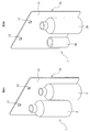
- package
- article
- packaging
- sticking
- Prior art date
- Legal status (The legal status is an assumption and is not a legal conclusion. Google has not performed a legal analysis and makes no representation as to the accuracy of the status listed.)
- Ceased
Links
Images






Classifications
-
- B—PERFORMING OPERATIONS; TRANSPORTING
- B65—CONVEYING; PACKING; STORING; HANDLING THIN OR FILAMENTARY MATERIAL
- B65B—MACHINES, APPARATUS OR DEVICES FOR, OR METHODS OF, PACKAGING ARTICLES OR MATERIALS; UNPACKING
- B65B53/00—Shrinking wrappers, containers, or container covers during or after packaging
-
- B—PERFORMING OPERATIONS; TRANSPORTING
- B65—CONVEYING; PACKING; STORING; HANDLING THIN OR FILAMENTARY MATERIAL
- B65D—CONTAINERS FOR STORAGE OR TRANSPORT OF ARTICLES OR MATERIALS, e.g. BAGS, BARRELS, BOTTLES, BOXES, CANS, CARTONS, CRATES, DRUMS, JARS, TANKS, HOPPERS, FORWARDING CONTAINERS; ACCESSORIES, CLOSURES, OR FITTINGS THEREFOR; PACKAGING ELEMENTS; PACKAGES
- B65D73/00—Packages comprising articles attached to cards, sheets or webs
Definitions
- the present invention relates to a packaging technique suitable for a packaging mode in which an article such as a product wrapped in a synthetic resin film is attached to a mount.
- Blister packs and packaged products with mounts are known as packaging modes for packaging products and other articles so that they can be displayed by covering them with a transparent or opaque synthetic resin film.
- a tubular shrink film is preliminarily attached to the mount as a transparent or opaque synthetic resin film like the mount with a tubular film disclosed in Patent Document 1.
- mount first put the article in the tubular shrink film, and then heat shrink the tubular shrink film to wrap the article and wrap it with the mount. And.
- the article is wrapped in a synthetic resin film such as a shrink film, and then the package is made of a double-sided tape or a hot melt adhesive. If it is attached to the mount by an adhesive means such as, the synthetic resin film can be neatly attached to the outer shape of the article, and it is easy to control the attachment position of the package to the mount after that. It can improve aesthetics and productivity.
- the outer shape of the article is a cylinder
- the area of the attachment portion between the article and the mount after being wrapped with the synthetic resin film becomes narrow (in a thin band shape). Therefore, the holding power of the package against the mount may not be sufficiently secured.
- the area of the attachment portion can be secured, but there is a problem that the mount is warped and deformed.
- the present invention has been made by paying attention to such a problem, and the synthetic resin film is used to sufficiently secure the holding force (adhesive strength) of the bonded portion between the article and the mount after packaging. It is an object of the present invention to provide a mount for a packaged product with a mount, a packaged product with a mount, an apparatus for manufacturing a packaged product with a mount, and a method for manufacturing the packaged product with a mount, which can prevent deformation of the mount due to sticking.
- the mount for a packaged product with a mount is a mount for attaching a package in which an article is wrapped in a synthetic resin film to obtain a packaged product with a mount. Therefore, it is possible to project to the side of the one surface by limiting the attachment portion set on one surface and the attachment portion to which the packaging body is attached and the portion other than the part of the attachment portion. It is characterized by including a slit formed so as to form a clear image area.
- the packaged product with a mount comprises a mount having a sticking portion set on one surface and an article wrapped with a synthetic resin film attached to the sticking portion of the mount. It is characterized in that a package is provided, and the mount for a packaged product with a mount according to one aspect of the present invention is used as the mount.
- the method for producing a packaged product with a mount according to one aspect of the present invention is a method for producing a packaged product with a mount according to one aspect of the present invention, in which the article is wrapped with the synthetic resin film and packaged.
- the one side of the mount is opposed to the package, and the imaged portion is attached to the outer shape of the article, and the coating is applied by an adhesive means such as a double-sided tape or a hot melt adhesive. It is characterized by including a sticking step of sticking the package to the dressing portion.
- the packaged product manufacturing apparatus with a mount according to one aspect of the present invention is a packaged product manufacturing apparatus with a mount for producing the packaged product with a mount according to one aspect of the present invention, and the article is packaged with the synthetic resin film.
- the packaging device to be used the bonding means supply device for supplying the bonding means such as double-sided tape or hot melt adhesive to the sticking portion of the mount, and the one surface of the mount facing the packaging body. By pressing the imaged portion from the side opposite to one surface, the imaged portion is attached to the outer shape of the article, and the package is attached to the adhesive portion to which the adhesive means is supplied. It is characterized by comprising a sticking device.
- the imaged portion provided on the attachment portion of the mount is attached to the outer shape of the article, and the article after packaging is attached with a synthetic resin film while the main body portion of the mount remains flat. Can be attached to the part. Therefore, it is possible to sufficiently secure the holding force (adhesive strength) of the sticking portion between the article and the mount after packaging and prevent the mount from being deformed by sticking.
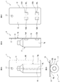
- FIG. 1 is a perspective view illustrating an embodiment of a packaged product with a mount according to an aspect of the present invention.
- 2A, 2B, 2C and 2D are explanatory views of an embodiment of a packaged product with a mount according to one aspect of the present invention, FIG. 2A is a front view thereof, FIG. 2B is a side view, and FIG. 2C is a side view.
- the rear view and FIG. 2D are plan views.
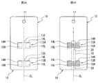
- 3A and 3B are explanatory views of an embodiment of a mount for a packaged product with a mount according to one aspect of the present invention, FIG. 3A is a front view in a state where an adhesive means is not arranged, and FIG. 3B is an adhesive means.
- FIG. 4 is a schematic view illustrating an embodiment of a packaged product manufacturing apparatus with a mount according to one aspect of the present invention.
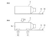
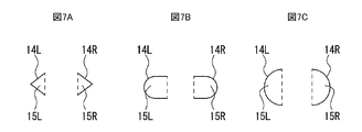
- 5A, 5B and 5C are schematic views illustrating a packaging process in the packaging product manufacturing apparatus of FIG. 6A and 6B are schematic views illustrating a sticking process in the packaging product manufacturing apparatus of FIG. 7A, 7B and 7C are visionary portions of the attachment portion and are views showing other examples of the cut shape of the slit.
- 8A and 8B are views showing another example of the final aspect of the packaged product with mount.
- 9A and 9B are diagrams showing other aspects of manufacturing a package with a mount.
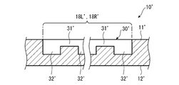
- FIG. 10 is an enlarged view of a main part for explaining a modified example of the mount for a packaged product with a mount according to one aspect of the present invention.
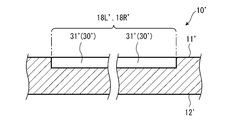
- FIG. 11 is a schematic view illustrating a first example of the cross section of the arrow XX portion of FIG.
- FIG. 12 is a schematic view illustrating a second example of the cross section of the arrow XX portion of FIG.
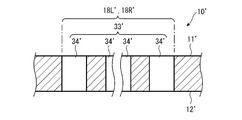
- FIG. 13 is a schematic view illustrating a third example of the cross section of the arrow XX portion of FIG.
- FIG. 14 is a schematic view illustrating a fourth example of the cross section of the arrow XX portion of FIG.
- FIG. 15 is a perspective view illustrating a modified example of the packaged product with a mount according to one aspect of the present invention.
- the packaged product 1 with a mount of the present embodiment includes a mount 10 and a package 2 attached to the front surface 11 of the mount 10.
- the mount 10 of this embodiment is made of cardboard.
- the mount 10 has a rectangular outer shape on the front surface 11 when viewed from the front, a circular hanging hole 17 is formed in the center of the upper portion, and the four corners are chamfered in an arc shape.
- Information such as an effect on the display and a description of the product to be packaged is printed on the front and back of the mount 10.
- the package 2 is an article 3 having a cylindrical outer shape portion 3 g wrapped with a shrink film 4 which is a synthetic resin film.
- the article 3 is, for example, a cosmetic product, in which the upper portion of the cylindrical outer shape portion 3g is formed in a truncated cone shape, and a screw cap is provided in the center of the upper portion.
- the attachment portions 13A and 13B are set on the mount 10, and the front surfaces 11 of the mount 10 are set on the attachment portions 13A and 13B.
- an adhesive means 20 such as a double-sided tape or a hot melt adhesive is supplied, and the package 2 is attached to the attachment portions 13A and 13B from the front surface 11 of the mount 10.
- the package 2 is attached with a position where the axis CL of the cylindrical outer shape portion 3 g is parallel to the long side or the short side (long side in this example) of the front surface 11. It is set to the planned position 16 (see the two-dot chain line portion in FIG. 3B).
- the position where the center of the rectangular front surface 11 and the axis CL coincide with each other is the scheduled attachment position 16.
- the attachment portions 13A and 13B are provided at a plurality of positions (two upper and lower positions in this example) along the axis CL of the cylindrical outer shape portion 3g with respect to the planned attachment position 16 of the package 2. Has been done.
- the mount 10 is set on the front surface 11 and has the attachment portions 13A and 13B to which the package 2 is attached, and a part of the attachment portions 13A and 13B.
- Slits 14L, 14R formed so as to form image parts 15L, 15R which can be bent or folded back toward the front surface 11 to project out, leaving 13s and limiting a part other than 13s.
- the slits 14L and 14R leave the central portion 13s of the attachment portions 13A and 13B as a part, and only the left and right side portions of the central portion 13s are bent or bent toward the front surface 11. It is formed so as to form two image forming portions 15L and 15R that can be folded back and overhanged.
- the sticking portions 13A and 13B are provided with two image portions 15L and 15R so as to be sandwiched from the left and right sides of the axis CL with the axis CL of the outer shape portion 3g as the center.
- the slits 14L and 14R are formed by cutting into a U shape in which the left and right side portions are [].
- the slits 14L and 14R are formed in advance when the mount 10 is punched.
- the broken line portion in FIG. 2C (in FIG. 3A, the portion of the rectangular broken line portion indicating the central portion 13s, the portion of the vertical line) is bent or folded back toward the front surface 11, and the drawing portions 15L and 15R are formed.
- the base end portion constituting the above is shown.
- the slits 14L and 14R of the present embodiment are formed when the front surface 11 is viewed from the front after the packaging body 2 is attached to the mount 10 as shown in FIGS. 1 and 2A to 2D.
- the image areas 15L and 15R are formed in a range hidden behind the package 2 and cannot be seen.
- the packaged product manufacturing apparatus 100 with a mount includes a conveyor 170 for transporting the article 3, the package 2, and the packaged product 1 with a mount.
- the conveyor 170 has a horizontal transport surface.
- the housing 110 is arranged at an appropriate position on the conveyor 170.
- the housing 110 is provided with a packaging device 120 at the upper part on the entry side, and a heating device 130 and a sticking device 140 are arranged in this order inside the housing 110.
- the packaging device 120 is equipped with a packaging means for packaging the article 3 with the shrink film 4.
- An adhesive supply device 160 and a mount supply device 150 are attached to the positions of the sticking device 140.
- the mount supply device 150 is arranged below the conveyor 170.
- the mount supply device 150 has a magazine that accommodates a plurality of mounts 10 (not shown below) and a carrier that arranges the mounts 10 accommodated in the magazines one by one at a predetermined position on the conveyor 170.
- the adhesive supply device 160 is configured to be able to supply the adhesive means 20 such as a hot melt adhesive to the mount 10 arranged at a predetermined position only in the range of the attachment portions 13A and 13B of the mount 10.
- the sticking device 140 has a manipulator configured so that the packaging body 2 in which the article 3 is wrapped in the shrink film 4 and the front surface 11 of the mount 10 face each other, and a pressing mechanism.
- the package 2 is placed in the lying position by the manipulator of the sticking device 140, and the article 3 is a shrink film as shown in FIG. 6A.
- the packaging body 2 packaged in 4 and the front surface 11 of the mount 10 face each other.
- the arrow indicated by the reference numeral R in FIG. 4 shows an image in which the package 2 is placed in a lying position and faces the front surface 11 of the mount 10 by a manipulator.
- the mount 10 when the mounts are arranged so as to face each other is in a state where the imaged portions 15L and 15R of the two attachment portions 13A and 13B are flat (face-to-face with the front surface 11).
- the adhesive supply device 160 applies the adhesive means 20 such as hot melt adhesive to the mount 10 arranged at a predetermined position only in the range of the attachment portions 13A and 13B of the mount 10. Supply (gluing process).
- the main body portion of the mount 10 remains flat by the pressing mechanism of the sticking device 140, and only the drawing portions 15L and 15R are attached to the outer shape of the article 3 to make it hot.
- the package 2 is attached to the upper and lower adhesive portions 13A and 13B by the adhesive means 20 which is a melt adhesive (adhesion step).
- the shrink film 4 is used to sufficiently secure the holding force (adhesive strength) of the attachment portions 13A and 13B between the article 3 and the mount 10 after packaging, and the other parts of the mount 10 are attached so as not to be attached. Therefore, it is possible to prevent deformation of the mount 10 due to sticking.
- the arrows indicated by reference numerals F3 in FIGS. 4 and 6B indicate an image in which the package 2 is pressed and held on the front surface 11 side of the mount 10 by a manipulator, and reference numerals F1 and F2 are shown in FIGS. 4 and 6B.
- the arrow indicated by is an image in which the upper and lower sticking portions 13A and 13B are pressed so as to follow the outer shape of the article 3 by the left and right image portions 15L and 15R, respectively.
- the package 2 in which the article 3 is wrapped in the shrink film 4 is attached to the planned attachment position 16 of the mount 10, and the package 1 with the mount is manufactured.
- the manufactured packaged product 1 with a mount is carried out to the next process downstream (arrow in OUT in FIG. 4).
- the mount 10 of the present embodiment As described above, according to the method of manufacturing the mount 10 for the package with the mount, the package 1 with the mount, the package manufacturing apparatus 100 with the mount, and the package 1 with the mount using the same, the mount 10 of the present embodiment.
- the article 3 is wrapped in a shrink film 4, and then the package 2 is attached by an adhesive means 20 such as a double-sided tape or a hot melt adhesive. Since it is attached to the mount 10, the shrink film 4 can be neatly attached to the outer shape of the article 3. Further, since it is easy to manage the attachment position of the package 2 with respect to the mount 10, the aesthetic appearance and productivity of the package 1 with the mount can be improved.
- a part 13s of the sticking portions 13A and 13B is left, and a part other than the part 13s is bent or folded back toward the front surface 11 to project. It is provided with slits 14L, 14R formed so as to form the components 15L, 15R.
- the attachment portions 13A and 13B to the mount 10 are attached to the cylindrical outer peripheral surface of the article 3 along only the drawing portions 15L and 15R, the areas of the attachment portions 13A and 13B are secured.
- the mount body can be left flat, the mount 10 does not warp and deform.
- the sticking portions 13A and 13B are provided with two image portions 15L and 15R so as to be sandwiched from the left and right sides of the axis CL with the axis CL of the outer shape portion 3g as the center. Therefore, it is suitable for ensuring sufficient holding power of the package 2 with respect to the mount 10.
- the imaged portions 15L and 15R are behind the packaging body 2. Since it is formed in a range hidden behind and invisible, it is suitable for improving the aesthetic appearance at the time of display while sufficiently securing the holding force of the package 2 with respect to the mount 10.
- the mount for the packaged product with the mount, the packaged product with the mount, and the packaging product manufacturing apparatus with the mount and the method for manufacturing the packaged product with the mount according to the present embodiment the synthetic resin film such as shrink film 4 or the like. It is possible to sufficiently secure the holding force (adhesive strength) of the attachment portions 13A and 13B between the article 3 and the mount 10 after packaging and prevent the mount 10 from being deformed by the attachment.
- the mount for the packaged product with the mount, the packaged product with the mount, the device for manufacturing the packaged product with the mount, and the method for manufacturing the packaged product with the mount according to the present invention are not limited to the above embodiments, and the method of manufacturing the packaged product with the mount is not limited to the above embodiment. Various modifications are possible without deviating from the purpose.
- the slits 14L and 14R may be cut into a triangular shape such as ⁇ > (FIG. 7A), or a U-shape. It may be cut into (Fig. 7B). Further, it may be cut into a semicircular shape (FIG. 7C), and the imaged portions 15L and 15R of the sticking portion can be configured to have a shape corresponding to each.
- the broken line portion of FIGS. 7A to 7C indicates a base end portion that is bent or folded back toward the front surface 11 to form the drawing portions 15L and 15R.
- the cutting step of the slits 14L and 14R has shown an example in which the slits 14L and 14R are formed in advance at the time of punching of the mount 10, but the present invention is not limited to this, and the packaging product manufacturing in which the packaging body 2 is attached to the mount 10 is not limited to this. It may be performed inside the machine of the device 100. Further, for example, in the above embodiment, regarding the method of adhering the package 2 to the hanging mount 10, in the gluing step, a hot melt adhesive is used as the adhesive means 20 inside the housing 110 of the package manufacturing apparatus 100. An example of supplying is shown, but the present invention is not limited to this.
- the front surface 11 of the mount 10 is set as one surface, and a hot melt adhesive is applied to the front surface 11 in advance, and the mounting position 16 of the mount 10 is planned to be attached.
- the hot melt adhesive may be melted by heat.
- the adhesive means 20 is not limited to the hot melt adhesive, and for example, double-sided tape may be used.
- the packaging mode of the article 3 is the packaging body 2 packaged with the shrink film 4, but the present invention is not limited to this, and a transparent or opaque synthetic resin film other than the shrink film is used. It may be present, or may be film packaging such as caramel packaging, three-way seal packaging, four-way seal packaging, and vertical pillow packaging. Further, it may be wrapped around the body.
- the outer shape of the mount 10 is rectangular is shown, but the outer shape of the mount 10 is not limited to the rectangle, and any outer shape can be set in addition to the rectangle.
- a free hole shape can be arbitrarily set in addition to the round hole.
- a plurality of packages 2 (two in FIG. 8A) can be attached to 10 at the same time (FIG. 8A), and the package 2 is not limited to the same shape, but has different shapes as shown in FIG. 8B, for example.
- a plurality of packages 2A and 2B can be attached to one mount 10.
- a plurality of hanging holes 17 (two in the examples of FIGS. 8A and 8B) may be provided.
- the shape of the hanging hole 17 is not limited to a circular shape, and may be an elliptical shape or a composite shape thereof in addition to a triangular hole and a rectangular hole.
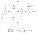
- the article 3 in the upright posture is wrapped with the shrink film 4 to form the package 2, and then the package 2 is set in the lying posture, and the front of the mount 10 is set in the lying posture.
- An example of sticking to the sticking portions 13A and 13B facing the surface 11 is shown, but the present invention is not limited to this.
- the sticking portion is opposed to the front surface 11 of the mount 10 in the standing posture. It may be attached to 13A and 13B.
- the article 3 in the prone position is wrapped with a synthetic resin film such as a shrink film to form a package 2, and then the article 3 in the prone position faces the front surface 11 of the mount 10 in the prone position. It may be attached to the attachment portions 13A and 13B.
- the example of FIG. 9B shows a plan view, and is an example in which a horizontal pillow package is formed by a three-way sticker having a seal portion on the bottom surface, and the horizontal pillow package is attached to the mount 10 in a lying position. The seal on the bottom is shown as an image.
- FIGS. 10 to 14 [Modification example of mount]
- a modified example mount 10' (mount for packaging with a mount) will be described with reference to FIGS. 10 to 14.
- the mount 10'of this modification has the same configuration as the above-described configuration except for a special description, and the same reference numerals are given to these configurations, and detailed description thereof will be omitted.
- the mount 10'of this modified example in addition to the slits 14L'and 14R'formed so as to form the imaged portions 15L'and 15R', the imaged portions 15L'and 15R' A weak portion 30'(indicated by a broken line for convenience of illustration) is provided at the base end portions 18L'and 18R'.
- the slit 14R'on the right side and the base end portion 18R' are provided in a D shape, and if the D shape is subdivided into an I shape and a C shape, the base end portion 18R'is located at the I-shaped portion.
- the left slit 14L'and the proximal end portion 18L' show an example in which the slit 14R'and the proximal end portion 18R'are provided symmetrically with respect to the slit 14R'and the proximal end portion 18R'.
- the weak portion 30'exemplified here is provided in each of the proximal end portions 18L'and 18R'in the same configuration.
- the weak portion 30' is a structure (repulsive force suppressing structure) for suppressing the repulsive force due to the overhang of the imaged portions 15L'and 15R' bent or folded back toward the front surface 11' (one surface). is there.
- the base end portions 18L'and 18R' that function as the pivots of the imageable portions 15L'and 15R' that project from the main body portion 19'(mounting paper main body portion) that remains flat on the mount 10'and can be displaced.
- a weak portion 30' is provided which intentionally reduces the rigidity (so-called "stiffness") or strength.
- Various structures can be applied to the weak portion 30'as long as the repulsive force due to the overhang of the image forming portions 15L'and 15R'can be suppressed by the base end portions 18L'and 18R'.
- a perforated structure 33'(see FIG. 13) penetrating in the thickness direction of the mount 10' is also illustrated.
- the recess 31' is a recessed portion in the thickness direction of the mount 10'.
- the recess 31' can be formed linearly by a recessing process such as embossing, embossing, or deep digging on the base end portions 18L'and 18R'.
- FIG. 11 shows an example in which a linear recess 31'continuous over the entire area of the base end portions 18L'and 18R' is compacted from the front surface 11'.
- the recess 31' may be provided only in a part of the base end portions 18L'and 18R', may be provided in various forms such as a wavy line (curve shape) and a broken line shape, and the back surface 12' may be provided. It may be recessed from.
- the half-cut portion 32' is a portion cut in the thickness direction of the mount 10'without penetrating in the thickness direction.
- the half-cut portion 32' can be formed by so-called half-cut processing (also referred to as "half-cut processing").
- FIG. 12 shows an example in which the half-cut portion 32', which is provided intermittently at the base end portions 18L'and 18R'and has a broken line shape along a straight line, is cut from the front surface 11'.
- the half-cut portion 32' may be continuously provided over the entire area of the base end portions 18L'and 18R', may be provided along lines having various shapes such as straight lines and wavy lines, and may be provided on the back surface. It may be cut from 12'.
- the perforated structure 33' is a structure in which all cut portions 34'that penetrate the mount 10'in the thickness direction and are cut in the thickness direction are intermittently provided.
- the perforation structure 33' is formed by intermittently arranging all cut portions 34'formed by so-called total cutting (also referred to as "total cutting") in a perforated pattern (that is, perforation). It is possible.
- FIG. 13 illustrates a perforated structure 33'that is intermittently provided at the base end portions 18L'and 18R'and in which all the cut portions 34' in the shape of a broken line along a straight line are cut.
- all the cut portions 34' may be cut intermittently along lines having various shapes such as straight lines and wavy lines. If all the cut portions 33'are provided over the entire area of the base end portions 18L'and 18R', the imaging portions 15L'and 15R'will be cut out. Therefore, in the base end portions 18L'and 18R', the entire cut portion 33'is intermittent so that the portion where the imaging portion 15L', 15R'and the main body portion 19'(see FIG. 10) are continuously connected remains intermittently. Is arranged as a target.
- One of these recesses 31', half-cut portion 32', and perforated structure 33' may be applied to the weak portion 30'alone, or a plurality of them may be applied to the weak portion 30'in combination. May be good.
- the recess 31'and the half-cut portion 32' may be arranged in the weak portion 30'.
- a processing procedure for the weak portion 30' after processing to intermittently provide the half-cut portion 32'at the proximal end portions 18L'and 18R' from the front surface 11', the proximal end portion 18L', An example is given in which a process of providing a continuous recess 31'over the entire area of 18R' is performed from the front surface 11'.
- the notch of the half-cut portion 32' is intermittently arranged at a position deeper than the recess 31' recessed from the front surface 11'.
- the weak portion 30' can be provided on the mount 10'by utilizing an existing processing device or method for embossing the mount 10'.
- the base end portions 18L'and 18R' are compacted, the base end portions 18L'and 18R'are suppressed while suppressing a decrease in strength connecting the image forming portions 15L'and 15R'and the main body portion 19'. It is possible to reduce the stiffness in the direction intersecting the extending direction of ′. By suppressing the rigidity in the direction in which the main body portion 19'and the drawing portions 15L'and 15R' are connected in this way, the repulsive force of the drawing portions 15L'and 15R'can be suppressed.
- the degree of suppression of the repulsive force can be adjusted by the depth of cut of the half-cut portion 32'. Therefore, an appropriate repulsive force can be set according to the thickness and properties of the mount 10', and it is also possible to suppress fluctuations in the repulsive force that may fluctuate depending on the manufacturing environment such as temperature and humidity.
- the perforated structure 33' is applied to the weak portion 30', a simple manufacturing method is provided because the entire cut portion 34'that does not require delicate adjustment of the depth of cut is provided like the half cut portion 32'.
- a weak portion 30' can be provided. Further, by adjusting the pitch (density) of all the cut portions 34'in the perforated structure 33', the degree of suppression of the repulsive force can be adjusted.
- the overhanging image areas 15L'and 15R' As an example of the recess 31'and the half-cut portion 32', when the weak portion 30'is processed from the front surface 11'of the mount 10'as described above, the overhanging image areas 15L'and 15R' The compression deformation on the front surface 11'side at the base end portions 18L'and 18R' is relaxed. As a result, the repulsive force can be efficiently suppressed.
- the weak portion 30' that does not penetrate in the thickness direction of the mount 10'such as the recess 31'and the half-cut portion 32', when a fluid material such as a hot melt adhesive is used for the adhesive means 20
- a fluid material such as a hot melt adhesive
- the protrusion of the fluidized material from the front surface 11'to the back surface 12' through the weak portion 30' is structurally avoided.
- the handleability of the mount 10'in the manufacturing process can be ensured, which contributes to the improvement of the quality of the mount 10'.
- the weak portion 30'in which at least two of the recess 31', the half-cut portion 32', and the perforated structure 33' are provided side by side the repulsive force due to the overhang of the imaged portions 15L'and 15R'is surely suppressed. Therefore, the degree of suppression of the repulsive force can be adjusted according to the number of recesses 31', half-cut portions 32', and perforated structures 33'.
- a second weak portion may be provided in the drawing portions 15L'and 15R' along with the base end portions 18L'and 18R'.
- the packaged product 1 ′′ with a mount of this modification is provided with a packaged body 2 ′′ in which the article 3 ′′ is packaged by the shrink film 4 ′′ as a synthetic resin film.
- the article 3 ′′ is packaged by the heat-shrinked shrink film 4 ′′.
- the package 2 ′′ corresponds to the edge of the shrink film 4 ′′ before the heat shrinkage.
- a linear seal portion 4S "(so-called” seal wire ") extends at the portion.
- the seal portion 4S ′′ is also referred to as a “seal wire” and is a linear mark generated when the edges of the shrink film are sealed to each other.
- FIG. 15 illustrates the seal portion 4S ′′ of the three-way pillow packaging.
- the shrink film 4 ′′ that is heat-shrinked and wraps the article 3 ′′ has a property of being easily broken starting from the seal portion 4S ′′.
- the shrink film 4 ′′ that wraps the article 3 is It is easy to tear with the seal part 4S "as a starting point.
- the shrink film 4 "of the package 2" can be broken and the article 3 "can be taken out. Therefore, the package 1" with the mount can be taken out. Usability can be improved.
- the shrink film 4 "is broken if the shrink film 4" remains attached to the attachment portions 13A “and 13B" (mounting sheet 10 ") via the adhesive means 20", the packaged product with the backing sheet 1 It is easy to dispose of the mount 10 ′′ and the shrink film 4 ′′ other than the article 3 ′′ together. From this point as well, it contributes to improving the usability of the packaged product 1 "with mount.
- the mount is not limited to the cardboard described above, and various materials can be used. From the viewpoint of ensuring printability and rigidity, it is preferable to use white paperboard as the mount. Among these white paperboards, it is more preferable to use coated balls, uncoated balls, high-grade paperboards, special paperboards, cup base papers and the like.
- the basis weight of the mount is 400 to 500 [g / m 2 ] from the viewpoint of ensuring the workability of the mount, suppressing the warp of the mount, and appropriately setting the repulsive force of the imaged portion.
- the mount is not limited to paper, and a resin or rubber mount may be used. When a mount that is not made of paper is used, it is preferable that an adhesive means suitable for the material is appropriately used.
- the hot melt adhesive used as the adhesive for the mount various known systems such as EVA type, olefin type, rubber type, polyamide type and polyester type can be appropriately used. Of these, a rubber-based hot melt adhesive is preferable from the viewpoint of ensuring durability, and an olefin-based hot melt adhesive is preferable from the viewpoint of ensuring compatibility with a polypropylene-based shrink film.
- a two-component curing type hot melt agent can also be used.
- the two-component curing type hot melt agents it is preferable to use a reaction type containing urethane resin as a main component from the viewpoint of ensuring high heat resistance and adhesiveness.
- a reaction-type hot melt agent when cooled, it solidifies in a form that leaves isocyanate groups, and after cooling, the water in the air reacts with the isocyanate groups to advance the polymer, resulting in higher heat resistance. Adhesiveness is obtained.
- shrink film various known films such as polyethylene terephthalate film, polyethylene film, polypropylene film and the like can be appropriately used. From the viewpoint of suppressing the occurrence of wrinkles during heat shrinkage (so-called “shrink”) and from the viewpoint of heat shrinkage at a low temperature, it is particularly preferable to use a polypropylene-based shrink film having a main composition of polyolefin.
Landscapes
- Engineering & Computer Science (AREA)
- Mechanical Engineering (AREA)
- Packages (AREA)
Abstract
Dans la présente invention, pour garantir une force de maintien (adhérence) adéquate entre des parties adhérentes d'un papier de base (10) et un produit (3) qui a été enveloppé dans un film de résine synthétique (4), et pour empêcher la déformation du papier de base (10) provoquée par l'adhérence, le papier de base (10) comprend : des parties adhérentes (13A, 13B) qui sont disposées sur une surface avant (11) et auxquelles un corps d'emballage (2) adhère ; et des fentes (14L, 14R) formées de telle sorte que des sections des parties adhérentes (13A, 13B) autres qu'une partie (13s) des parties adhérentes sont conçues en tant que sections définies (15L, 15R) qui peuvent faire saillie à partir de la surface avant (11).
Applications Claiming Priority (2)
| Application Number | Priority Date | Filing Date | Title |
|---|---|---|---|
| JP2019135846 | 2019-07-24 | ||
| JP2019-135846 | 2019-07-24 |
Publications (1)
| Publication Number | Publication Date |
|---|---|
| WO2021015263A1 true WO2021015263A1 (fr) | 2021-01-28 |
Family
ID=74193069
Family Applications (1)
| Application Number | Title | Priority Date | Filing Date |
|---|---|---|---|
| PCT/JP2020/028525 Ceased WO2021015263A1 (fr) | 2019-07-24 | 2020-07-22 | Papier de base pour produit emballé avec du papier de base, produit emballé avec du papier de base, dispositif permettant de fabriquer un produit emballé avec du papier de base, et procédé de fabrication d'un produit emballé avec du papier de base |
Country Status (2)
| Country | Link |
|---|---|
| JP (2) | JP7593585B2 (fr) |
| WO (1) | WO2021015263A1 (fr) |
Families Citing this family (1)
| Publication number | Priority date | Publication date | Assignee | Title |
|---|---|---|---|---|
| JP7598829B2 (ja) * | 2021-07-02 | 2024-12-12 | 株式会社フジシール | 台紙およびフィルム付き台紙 |
Citations (6)
| Publication number | Priority date | Publication date | Assignee | Title |
|---|---|---|---|---|
| JPS54126981U (fr) * | 1978-02-22 | 1979-09-04 | ||
| JPH0429966A (ja) * | 1990-04-06 | 1992-01-31 | Taoka Chem Co Ltd | 3,5−ジクロロ−4−エチル−2−ヒドロキシベンゼンスルホン酸の製造方法 |
| JP2012025483A (ja) * | 2010-07-28 | 2012-02-09 | Fuji Seal International Inc | 支持体 |
| JP2014141264A (ja) * | 2013-01-22 | 2014-08-07 | Toyo Ink Sc Holdings Co Ltd | 台紙付き包装体の製造方法 |
| US20150114869A1 (en) * | 2013-10-25 | 2015-04-30 | National Concessions Group Inc. | Product packaging with removable indicia |
| JP2017052538A (ja) * | 2015-09-09 | 2017-03-16 | 凸版印刷株式会社 | シュリンクフィルム付台紙の製造方法及びシュリンクフィルム付台紙製造装置 |
Family Cites Families (9)
| Publication number | Priority date | Publication date | Assignee | Title |
|---|---|---|---|---|
| JPH0126619Y2 (fr) * | 1984-11-30 | 1989-08-09 | ||
| JPH0740530U (ja) * | 1993-12-28 | 1995-07-18 | 岡本印刷株式会社 | 包装容器 |
| JP2001206364A (ja) * | 2000-01-31 | 2001-07-31 | Mitsubishi Plastics Ind Ltd | 折り曲げ罫線入りプラスチックシート及び包装ケース |
| JP2006095934A (ja) * | 2004-09-30 | 2006-04-13 | Toppan Printing Co Ltd | リード罫及びリード罫が形成された紙器用ブランク並びにリード罫形成用刃物 |
| JP2013252869A (ja) * | 2012-06-05 | 2013-12-19 | Sigma Shigyo Kk | 包装体 |
| JP6200700B2 (ja) * | 2013-06-19 | 2017-09-20 | 株式会社フジシールインターナショナル | 包材および包装体 |
| JP6340189B2 (ja) * | 2013-11-28 | 2018-06-06 | 花王株式会社 | 台紙付包装体 |
| JP6167080B2 (ja) * | 2014-08-29 | 2017-07-19 | アイパックスイケタニ株式会社 | 台紙付き起立包装体 |
| JP6875145B2 (ja) * | 2017-02-21 | 2021-05-19 | 株式会社フジシール | 台紙及び筒状フィルム付き台紙 |
-
2020
- 2020-07-22 JP JP2020125579A patent/JP7593585B2/ja active Active
- 2020-07-22 WO PCT/JP2020/028525 patent/WO2021015263A1/fr not_active Ceased
-
2022
- 2022-11-08 JP JP2022179060A patent/JP2023001268A/ja active Pending
Patent Citations (6)
| Publication number | Priority date | Publication date | Assignee | Title |
|---|---|---|---|---|
| JPS54126981U (fr) * | 1978-02-22 | 1979-09-04 | ||
| JPH0429966A (ja) * | 1990-04-06 | 1992-01-31 | Taoka Chem Co Ltd | 3,5−ジクロロ−4−エチル−2−ヒドロキシベンゼンスルホン酸の製造方法 |
| JP2012025483A (ja) * | 2010-07-28 | 2012-02-09 | Fuji Seal International Inc | 支持体 |
| JP2014141264A (ja) * | 2013-01-22 | 2014-08-07 | Toyo Ink Sc Holdings Co Ltd | 台紙付き包装体の製造方法 |
| US20150114869A1 (en) * | 2013-10-25 | 2015-04-30 | National Concessions Group Inc. | Product packaging with removable indicia |
| JP2017052538A (ja) * | 2015-09-09 | 2017-03-16 | 凸版印刷株式会社 | シュリンクフィルム付台紙の製造方法及びシュリンクフィルム付台紙製造装置 |
Also Published As
| Publication number | Publication date |
|---|---|
| JP2021020738A (ja) | 2021-02-18 |
| JP2023001268A (ja) | 2023-01-04 |
| JP7593585B2 (ja) | 2024-12-03 |
Similar Documents
| Publication | Publication Date | Title |
|---|---|---|
| CA2771801C (fr) | Procede de fixation de languettes de saisie d'une couche de support de pansement film | |
| JP2021020738A (ja) | 台紙付き包装品用台紙、台紙付き包装品、並びに、台紙付き包装品製造装置および台紙付き包装品の製造方法 | |
| JP2013094974A (ja) | 配送伝票 | |
| JPH10503998A (ja) | 短いフラップを備えた箱を部分粘着テープにより封止する方法及び該方法により形成したパッケージ | |
| US11702268B2 (en) | Bonding label | |
| JP2013163523A (ja) | スキンパック包装体 | |
| JP2018135116A (ja) | 台紙及び筒状フィルム付き台紙 | |
| JPH1072063A (ja) | 包装作業性を改善したプラスチック気泡シート | |
| JP2011148528A (ja) | ブリスター容器、及びブリスター容器の製造方法 | |
| JP2015030480A (ja) | 製品保持具 | |
| US8101256B1 (en) | Label structure including a two ply reclosable flap | |
| JP3145144U (ja) | ブリスター包装台紙 | |
| JP6023975B2 (ja) | シュリンクフィルム付き台紙、包装体、及び包装体の製造方法 | |
| US6645592B1 (en) | Laminated liner system | |
| JP2007003724A (ja) | 巻付けラベル、及び巻付けラベル連続体 | |
| JP2021020736A (ja) | 台紙付き包装品用台紙、台紙付き包装品、並びに、台紙付き包装品製造装置および台紙付き包装品の製造方法 | |
| JP2021020738A5 (fr) | ||
| JP5117144B2 (ja) | 積層ラベル | |
| JP4847368B2 (ja) | 収納ラベル | |
| JP2020193273A (ja) | 両面接着テープ、テープロール及び梱包用箱 | |
| JP6585364B2 (ja) | 包装体 | |
| JP2014105011A (ja) | 結束ラベル、及び包装体 | |
| JP6919737B2 (ja) | 剥離ラベル、連続剥離ラベル、配送伝票 | |
| JPH0752970A (ja) | 台板付き商品包装体及びその製造方法 | |
| JP2015189504A (ja) | 貼付対象物の供給用帯状体 |
Legal Events
| Date | Code | Title | Description |
|---|---|---|---|
| 121 | Ep: the epo has been informed by wipo that ep was designated in this application |
Ref document number: 20845082 Country of ref document: EP Kind code of ref document: A1 |
|
| NENP | Non-entry into the national phase |
Ref country code: DE |
|
| 122 | Ep: pct application non-entry in european phase |
Ref document number: 20845082 Country of ref document: EP Kind code of ref document: A1 |