WO2021024992A1 - 医療用チューブの先端位置検出システム - Google Patents
医療用チューブの先端位置検出システム Download PDFInfo
- Publication number
- WO2021024992A1 WO2021024992A1 PCT/JP2020/029697 JP2020029697W WO2021024992A1 WO 2021024992 A1 WO2021024992 A1 WO 2021024992A1 JP 2020029697 W JP2020029697 W JP 2020029697W WO 2021024992 A1 WO2021024992 A1 WO 2021024992A1
- Authority
- WO
- WIPO (PCT)
- Prior art keywords
- tube
- light
- light emitting
- detection system
- position detection
- Prior art date
- Legal status (The legal status is an assumption and is not a legal conclusion. Google has not performed a legal analysis and makes no representation as to the accuracy of the status listed.)
- Ceased
Links
Images





Classifications
-
- A—HUMAN NECESSITIES
- A61—MEDICAL OR VETERINARY SCIENCE; HYGIENE
- A61J—CONTAINERS SPECIALLY ADAPTED FOR MEDICAL OR PHARMACEUTICAL PURPOSES; DEVICES OR METHODS SPECIALLY ADAPTED FOR BRINGING PHARMACEUTICAL PRODUCTS INTO PARTICULAR PHYSICAL OR ADMINISTERING FORMS; DEVICES FOR ADMINISTERING FOOD OR MEDICINES ORALLY; BABY COMFORTERS; DEVICES FOR RECEIVING SPITTLE
- A61J15/00—Feeding-tubes for therapeutic purposes
-
- A—HUMAN NECESSITIES
- A61—MEDICAL OR VETERINARY SCIENCE; HYGIENE
- A61M—DEVICES FOR INTRODUCING MEDIA INTO, OR ONTO, THE BODY; DEVICES FOR TRANSDUCING BODY MEDIA OR FOR TAKING MEDIA FROM THE BODY; DEVICES FOR PRODUCING OR ENDING SLEEP OR STUPOR
- A61M25/00—Catheters; Hollow probes
- A61M25/01—Introducing, guiding, advancing, emplacing or holding catheters
- A61M25/0105—Steering means as part of the catheter or advancing means; Markers for positioning
-
- A—HUMAN NECESSITIES
- A61—MEDICAL OR VETERINARY SCIENCE; HYGIENE
- A61J—CONTAINERS SPECIALLY ADAPTED FOR MEDICAL OR PHARMACEUTICAL PURPOSES; DEVICES OR METHODS SPECIALLY ADAPTED FOR BRINGING PHARMACEUTICAL PRODUCTS INTO PARTICULAR PHYSICAL OR ADMINISTERING FORMS; DEVICES FOR ADMINISTERING FOOD OR MEDICINES ORALLY; BABY COMFORTERS; DEVICES FOR RECEIVING SPITTLE
- A61J15/00—Feeding-tubes for therapeutic purposes
- A61J15/0026—Parts, details or accessories for feeding-tubes
- A61J15/008—Sensor means, e.g. for sensing reflux, acidity or pressure
- A61J15/0088—Sensor means, e.g. for sensing reflux, acidity or pressure for sensing parameters related to the device
-
- A—HUMAN NECESSITIES
- A61—MEDICAL OR VETERINARY SCIENCE; HYGIENE
- A61B—DIAGNOSIS; SURGERY; IDENTIFICATION
- A61B90/00—Instruments, implements or accessories specially adapted for surgery or diagnosis and not covered by any of the groups A61B1/00 - A61B50/00, e.g. for luxation treatment or for protecting wound edges
- A61B90/39—Markers, e.g. radio-opaque or breast lesions markers
-
- A—HUMAN NECESSITIES
- A61—MEDICAL OR VETERINARY SCIENCE; HYGIENE
- A61J—CONTAINERS SPECIALLY ADAPTED FOR MEDICAL OR PHARMACEUTICAL PURPOSES; DEVICES OR METHODS SPECIALLY ADAPTED FOR BRINGING PHARMACEUTICAL PRODUCTS INTO PARTICULAR PHYSICAL OR ADMINISTERING FORMS; DEVICES FOR ADMINISTERING FOOD OR MEDICINES ORALLY; BABY COMFORTERS; DEVICES FOR RECEIVING SPITTLE
- A61J15/00—Feeding-tubes for therapeutic purposes
- A61J15/0011—Feeding-tubes for delivery of nourishment to the mouth; Mouth pieces therefor
-
- A—HUMAN NECESSITIES
- A61—MEDICAL OR VETERINARY SCIENCE; HYGIENE
- A61J—CONTAINERS SPECIALLY ADAPTED FOR MEDICAL OR PHARMACEUTICAL PURPOSES; DEVICES OR METHODS SPECIALLY ADAPTED FOR BRINGING PHARMACEUTICAL PRODUCTS INTO PARTICULAR PHYSICAL OR ADMINISTERING FORMS; DEVICES FOR ADMINISTERING FOOD OR MEDICINES ORALLY; BABY COMFORTERS; DEVICES FOR RECEIVING SPITTLE
- A61J15/00—Feeding-tubes for therapeutic purposes
- A61J15/0026—Parts, details or accessories for feeding-tubes
-
- A—HUMAN NECESSITIES
- A61—MEDICAL OR VETERINARY SCIENCE; HYGIENE
- A61J—CONTAINERS SPECIALLY ADAPTED FOR MEDICAL OR PHARMACEUTICAL PURPOSES; DEVICES OR METHODS SPECIALLY ADAPTED FOR BRINGING PHARMACEUTICAL PRODUCTS INTO PARTICULAR PHYSICAL OR ADMINISTERING FORMS; DEVICES FOR ADMINISTERING FOOD OR MEDICINES ORALLY; BABY COMFORTERS; DEVICES FOR RECEIVING SPITTLE
- A61J15/00—Feeding-tubes for therapeutic purposes
- A61J15/0026—Parts, details or accessories for feeding-tubes
- A61J15/008—Sensor means, e.g. for sensing reflux, acidity or pressure
- A61J15/0084—Sensor means, e.g. for sensing reflux, acidity or pressure for sensing parameters related to the patient
-
- A—HUMAN NECESSITIES
- A61—MEDICAL OR VETERINARY SCIENCE; HYGIENE
- A61M—DEVICES FOR INTRODUCING MEDIA INTO, OR ONTO, THE BODY; DEVICES FOR TRANSDUCING BODY MEDIA OR FOR TAKING MEDIA FROM THE BODY; DEVICES FOR PRODUCING OR ENDING SLEEP OR STUPOR
- A61M25/00—Catheters; Hollow probes
- A61M25/01—Introducing, guiding, advancing, emplacing or holding catheters
- A61M25/0102—Insertion or introduction using an inner stiffening member, e.g. stylet or push-rod
-
- A—HUMAN NECESSITIES
- A61—MEDICAL OR VETERINARY SCIENCE; HYGIENE
- A61M—DEVICES FOR INTRODUCING MEDIA INTO, OR ONTO, THE BODY; DEVICES FOR TRANSDUCING BODY MEDIA OR FOR TAKING MEDIA FROM THE BODY; DEVICES FOR PRODUCING OR ENDING SLEEP OR STUPOR
- A61M39/00—Tubes, tube connectors, tube couplings, valves, access sites or the like, specially adapted for medical use
- A61M39/10—Tube connectors; Tube couplings
-
- A—HUMAN NECESSITIES
- A61—MEDICAL OR VETERINARY SCIENCE; HYGIENE
- A61B—DIAGNOSIS; SURGERY; IDENTIFICATION
- A61B17/00—Surgical instruments, devices or methods
- A61B2017/00681—Aspects not otherwise provided for
- A61B2017/00734—Aspects not otherwise provided for battery operated
-
- A—HUMAN NECESSITIES
- A61—MEDICAL OR VETERINARY SCIENCE; HYGIENE
- A61B—DIAGNOSIS; SURGERY; IDENTIFICATION
- A61B90/00—Instruments, implements or accessories specially adapted for surgery or diagnosis and not covered by any of the groups A61B1/00 - A61B50/00, e.g. for luxation treatment or for protecting wound edges
- A61B90/30—Devices for illuminating a surgical field, the devices having an interrelation with other surgical devices or with a surgical procedure
- A61B2090/306—Devices for illuminating a surgical field, the devices having an interrelation with other surgical devices or with a surgical procedure using optical fibres
-
- A—HUMAN NECESSITIES
- A61—MEDICAL OR VETERINARY SCIENCE; HYGIENE
- A61B—DIAGNOSIS; SURGERY; IDENTIFICATION
- A61B90/00—Instruments, implements or accessories specially adapted for surgery or diagnosis and not covered by any of the groups A61B1/00 - A61B50/00, e.g. for luxation treatment or for protecting wound edges
- A61B90/30—Devices for illuminating a surgical field, the devices having an interrelation with other surgical devices or with a surgical procedure
- A61B2090/309—Devices for illuminating a surgical field, the devices having an interrelation with other surgical devices or with a surgical procedure using white LEDs
-
- A—HUMAN NECESSITIES
- A61—MEDICAL OR VETERINARY SCIENCE; HYGIENE
- A61B—DIAGNOSIS; SURGERY; IDENTIFICATION
- A61B90/00—Instruments, implements or accessories specially adapted for surgery or diagnosis and not covered by any of the groups A61B1/00 - A61B50/00, e.g. for luxation treatment or for protecting wound edges
- A61B90/36—Image-producing devices or illumination devices not otherwise provided for
- A61B90/37—Surgical systems with images on a monitor during operation
- A61B2090/373—Surgical systems with images on a monitor during operation using light, e.g. by using optical scanners
-
- A—HUMAN NECESSITIES
- A61—MEDICAL OR VETERINARY SCIENCE; HYGIENE
- A61B—DIAGNOSIS; SURGERY; IDENTIFICATION
- A61B90/00—Instruments, implements or accessories specially adapted for surgery or diagnosis and not covered by any of the groups A61B1/00 - A61B50/00, e.g. for luxation treatment or for protecting wound edges
- A61B90/36—Image-producing devices or illumination devices not otherwise provided for
- A61B90/37—Surgical systems with images on a monitor during operation
- A61B2090/376—Surgical systems with images on a monitor during operation using X-rays, e.g. fluoroscopy
-
- A—HUMAN NECESSITIES
- A61—MEDICAL OR VETERINARY SCIENCE; HYGIENE
- A61B—DIAGNOSIS; SURGERY; IDENTIFICATION
- A61B90/00—Instruments, implements or accessories specially adapted for surgery or diagnosis and not covered by any of the groups A61B1/00 - A61B50/00, e.g. for luxation treatment or for protecting wound edges
- A61B90/39—Markers, e.g. radio-opaque or breast lesions markers
- A61B2090/3937—Visible markers
-
- A—HUMAN NECESSITIES
- A61—MEDICAL OR VETERINARY SCIENCE; HYGIENE
- A61B—DIAGNOSIS; SURGERY; IDENTIFICATION
- A61B90/00—Instruments, implements or accessories specially adapted for surgery or diagnosis and not covered by any of the groups A61B1/00 - A61B50/00, e.g. for luxation treatment or for protecting wound edges
- A61B90/39—Markers, e.g. radio-opaque or breast lesions markers
- A61B2090/3937—Visible markers
- A61B2090/3945—Active visible markers, e.g. light emitting diodes
-
- A—HUMAN NECESSITIES
- A61—MEDICAL OR VETERINARY SCIENCE; HYGIENE
- A61J—CONTAINERS SPECIALLY ADAPTED FOR MEDICAL OR PHARMACEUTICAL PURPOSES; DEVICES OR METHODS SPECIALLY ADAPTED FOR BRINGING PHARMACEUTICAL PRODUCTS INTO PARTICULAR PHYSICAL OR ADMINISTERING FORMS; DEVICES FOR ADMINISTERING FOOD OR MEDICINES ORALLY; BABY COMFORTERS; DEVICES FOR RECEIVING SPITTLE
- A61J15/00—Feeding-tubes for therapeutic purposes
- A61J15/0003—Nasal or oral feeding-tubes, e.g. tube entering body through nose or mouth
-
- A—HUMAN NECESSITIES
- A61—MEDICAL OR VETERINARY SCIENCE; HYGIENE
- A61M—DEVICES FOR INTRODUCING MEDIA INTO, OR ONTO, THE BODY; DEVICES FOR TRANSDUCING BODY MEDIA OR FOR TAKING MEDIA FROM THE BODY; DEVICES FOR PRODUCING OR ENDING SLEEP OR STUPOR
- A61M39/00—Tubes, tube connectors, tube couplings, valves, access sites or the like, specially adapted for medical use
- A61M39/10—Tube connectors; Tube couplings
- A61M2039/1033—Swivel nut connectors, e.g. threaded connectors, bayonet-connectors
-
- A—HUMAN NECESSITIES
- A61—MEDICAL OR VETERINARY SCIENCE; HYGIENE
- A61M—DEVICES FOR INTRODUCING MEDIA INTO, OR ONTO, THE BODY; DEVICES FOR TRANSDUCING BODY MEDIA OR FOR TAKING MEDIA FROM THE BODY; DEVICES FOR PRODUCING OR ENDING SLEEP OR STUPOR
- A61M25/00—Catheters; Hollow probes
- A61M25/01—Introducing, guiding, advancing, emplacing or holding catheters
Definitions
- the present invention relates to a system for detecting the position of the tip of a tube inserted into the human body.
- tube feeding is widely used in which various medical tubes are inserted into the body cavity of a patient for treatment.
- a medical tube referred to as an oral / nasal tube, hereinafter simply referred to as an oral / nasal tube
- Oral and nasal tube feeding is performed by delivering nutritional supplements directly to the stomach via a "tube").
- the tip of the tube When performing oral or nasal tube feeding, the tip of the tube must be securely located in the stomach. Misinsertion of the tube into the trachea / bronchus is extremely dangerous. It is necessary to accurately confirm the position of the tube tip in the patient's body.
- X-ray fluoroscopy is the most reliable method for confirming the position of the tube tip. However, it is necessary to move the patient to the X-ray device for confirmation, which puts a heavy burden on the patient's body. The tube remains in place in the patient for several days. During that time, the tip of the tube may move due to cough reflex or vomiting. Therefore, it is necessary to confirm the position of the tip at predetermined time intervals. If X-ray fluoroscopy is performed each time, the burden on the patient is further increased, and the X-ray exposure dose is also increased.
- a method of measuring the pH of the liquid sucked through the tube to determine whether or not the tip of the tube is in the stomach may be used.
- this method is less reliable for patients with suppressed gastric acid secretion.
- Patent Document 1 describes a method of confirming the position of the tube tip by inserting a tube into which an optical fiber is inserted in advance into a patient and observing the light radiated from the tip of the optical fiber from outside the body. This method is simple and does not burden the patient.
- Patent Document 1 can be used only when the tube is first inserted into the patient, and cannot be used for the subsequent periodic confirmation of the tube tip position.
- An object of the present invention is to easily, accurately and safely detect the position of the tip of a tube inserted into a patient.
- the present invention relates to a medical tube tip position detection system for detecting the position of the tip of a tube inserted into a patient.
- the system comprises a light source device that emits light, a hollow tube having a flow path through which a liquid can pass, and a tube such that light from the light source device can enter the end face of the base end of the tube. It includes a connector provided at the base end and a light emitting portion provided at the tip of the tube. The light from the light source device is passed through the tube and emitted from the light emitting unit, and the light from the light emitting unit is transmitted to the body surface.
- the position of the tip of the tube inserted into the patient can be detected easily, accurately and safely.
- FIG. 1 shows a schematic configuration of a tip position detection system for a medical tube according to a first embodiment of the present invention.
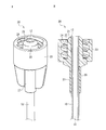
- FIG. 2A is a perspective view of the connector according to the first embodiment of the present invention.
- FIG. 2B is a cross-sectional view of the connector.
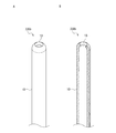
- FIG. 3A is a perspective view of a light emitting portion according to the first embodiment of the present invention.
- FIG. 3B is a cross-sectional view of the light emitting portion.
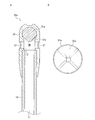
- FIG. 4A is a cross-sectional view of another light emitting portion according to the first embodiment of the present invention.
- FIG. 4B is a front view of the reflecting surface of the reflecting member of the light emitting portion.
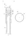
- FIG. 5A is a cross-sectional view of still another light emitting portion according to the first embodiment of the present invention.
- FIG. 5B is a front view of the reflecting surface of the reflecting member of the light emitting portion.
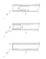
- 6A to 6C are cross-sectional views of still another light emitting portion according to the first embodiment of the present invention.
- FIG. 7A is a perspective view of the light emitting portion according to the second embodiment of the present invention.
- FIG. 7B is a cross-sectional view of the light emitting portion.
- FIG. 8A is an exploded perspective view of the light emitting portion according to the second embodiment of the present invention as viewed from the tip end side.
- FIG. 8B is an exploded perspective view seen from the base end side of the light emitting portion.
- FIG. 9A is a cross-sectional view of another light emitting portion according to the second embodiment of the present invention.
- FIG. 9B is an exploded perspective view seen from the tip end side of the light emitting portion.
- FIG. 10 is a cross-sectional view of still another light emitting portion according to the second embodiment of the present invention.
- FIG. 11A is a side view of the light emitting portion according to the third embodiment of the present invention.
- FIG. 11B is a perspective view of the light emitting portion.
- FIG. 12A is a perspective view of another light emitting unit according to the third embodiment of the present invention.
- FIG. 12B is a cross-sectional perspective view of the light emitting portion.
- FIG. 13A is a perspective view of still another light emitting unit according to the third embodiment of the present invention.
- FIG. 13A is a perspective view of still another light emitting unit according to the third embodiment of the present invention.
- FIG. 13B is a cross-sectional perspective view of the light emitting portion.
- FIG. 14A is a perspective view of still another light emitting unit according to the third embodiment of the present invention.
- FIG. 14B is a cross-sectional perspective view of the light emitting portion.
- FIG. 15A is a perspective view of still another light emitting unit according to the third embodiment of the present invention.
- FIG. 15B is a cross-sectional perspective view of the light emitting portion.
- the wavelength of the light emitted by the light source device may be 360 nm to 3000 nm.
- Light of this wavelength has high transmittance to the human body, which makes it easy to detect the position of the tube tip.
- light of this wavelength is minimally invasive to the human body, and is therefore excellent in safety.
- the connector includes a tubular male member into which the tube is inserted, an outer cylinder surrounding the male member, and a female screw formed on an inner peripheral surface of the outer cylinder facing the male member. May be good. Thereby, oral / nasal tube feeding can be performed by using a tube provided with the connector of the present invention instead of the conventional oral / nasal tube. Since the tube is inserted into the male member, it is easy to inject light from the light source device into the end face of the base end of the tube.
- the end face of the base end of the tube may be exposed to the opening at the tip of the male member.
- Such an embodiment is advantageous for incident light from the light source device on the end face of the proximal end of the tube.
- the light emitting unit may include a reflecting member that reflects the light emitted from the tube.
- the reflecting member reflects the light emitted from the tube in various directions including the radial direction (the direction perpendicular to the longitudinal direction of the tube). Therefore, regardless of the orientation of the light emitting portion in the patient's body, it becomes easy to observe the light from the light emitting portion from the patient's body surface.
- the reflective member may have a spherical surface or a conical surface on the side facing the end surface of the tip of the tube. This makes it possible to reflect the light emitted from the tube in various directions including the radial direction with a simple configuration.
- the reflective member may be made of titanium. Since titanium is excellent in corrosion resistance and biocompatibility, such an embodiment is advantageous for maintaining good light reflection characteristics for a long period of time.
- the reflective member may be provided in direct contact with the tube. Such an aspect is advantageous in simplifying the configuration of the light emitting portion and facilitating the manufacture of the tube provided with the light emitting portion.
- the housing can be omitted in the light emitting portion.
- the reflective member may be a metal vapor deposition layer. According to such an aspect, the reflective member can be easily provided on the tube.
- the light emitting unit may include a refracting member that refracts the light emitted from the tube.
- the refracting member refracts the light emitted from the tube in various directions including the radial direction. Therefore, regardless of the orientation of the light emitting portion in the patient's body, it becomes easy to observe the light from the light emitting portion from the patient's body surface.
- the light emitting unit may include the tip of the tube formed so that the light passing through the tube is refracted and emitted. According to this aspect, the light that has passed through the tube is refracted in various directions including the radial direction and emitted from the tube. Therefore, regardless of the orientation of the light emitting portion in the patient's body, it becomes easy to observe the light from the light emitting portion from the patient's body surface.
- the light emitting portion may include a hole penetrating the tube or a recess provided on the inner or outer surface of the tube. According to this aspect, the light that has passed through the tube is refracted at the holes or recesses and emitted from the tube in various directions including the radial direction. Therefore, regardless of the orientation of the light emitting portion in the patient's body, it becomes easy to observe the light from the light emitting portion from the patient's body surface.
- the outer surface of the tube may be provided with a light leakage prevention layer for preventing light leakage from the outer surface of the tube.
- the leakage light prevention layer may be removed from the light emitting portion. According to such an embodiment, the light that has passed through the tube is refracted from the region where the light leakage prevention layer is removed and emitted in various directions including the radial direction. Therefore, it is possible to observe the light from the light emitting portion from the surface of the patient's body by a simple method regardless of the orientation of the light emitting portion in the patient's body.
- the light emitting unit may include a housing.
- the housing may be provided with holes that allow the liquid that has passed through the tube to flow out to the outside world. According to such an embodiment, the liquid that has passed through the flow path of the tube can be administered to the patient through the hole of the housing. Further, the housing can be used to hold the reflective member or the refracting member at a desired position with respect to the end face of the tip of the tube.
- the light emitting unit may include a housing having translucency. According to such an embodiment, the light loss when the light emitted from the tip of the tube passes through the housing is reduced. This is advantageous for ensuring the brightness of the light emitting portion and facilitates the detection of the tube tip position.
- the surface roughness Ra of the outer surface of the tube may be 1.2 ⁇ m or less. According to such an embodiment, the light loss as the light passes through the tube is reduced. This is advantageous for ensuring the brightness of the light emitting portion and facilitates the detection of the tube tip position.
- the outer surface of the tube may be covered with a coating material having a lower refractive index than the tube. According to such an embodiment, the light loss as the light passes through the tube is reduced. This is advantageous for ensuring the brightness of the light emitting portion and facilitates the detection of the tube tip position.
- the system of the present invention may further include a stylet or optical fiber that can be inserted into and removed from the flow path of the tube.
- Stylets and optical fibers improve tube insertability.
- the stylet also allows the position of the tube to be confirmed by fluoroscopy.
- the optical fiber improves the brightness of the light emitting part and facilitates the detection of the tube tip position.
- FIG. 1 shows a schematic configuration of a system 1 according to a first embodiment of the present invention applied to oral and nasal tube feeding.
- An oral / nasal tube (hereinafter, simply referred to as a tube) 10 is inserted through the nasal cavity of the patient 90, and the tip thereof reaches the stomach 91.
- the tube 10 has flexibility that allows it to be curved and deformed.
- the tube 10 is a hollow tubular object in which a continuous flow path 11 (see FIGS. 2B and 3B described later) is formed over the entire length thereof.
- a liquid such as a nutritional supplement is administered to the patient's stomach 91 through the flow path 11.
- a connector 20 is provided at the base end of the tube 10.
- a light emitting unit 30 is provided at the tip of the tube 10.
- the connector 20 can be repeatedly connected to and separated from the light source device 50.
- the light from the light source (not shown) built in the light source device 50 passes through the tube 10 and is emitted from the light emitting unit 30.
- the light from the light emitting unit 30 passes through the body of the patient 90 and illuminates the body surface. The surgeon can confirm the position of the tip of the tube 10 from the light emitting position on the body surface of the patient 90.
- FIG. 2A is a perspective view of the connector 20, and FIG. 2B is a cross-sectional view of the connector 20.
- the connector 20 is a male connector including a tubular male member 21.
- the outer peripheral surface 22 of the male member 21 is a tapered surface (so-called male tapered surface) whose outer diameter decreases as it approaches the tip.
- the cylindrical outer cylinder 23 is arranged coaxially with the male member 21.
- the outer cylinder 23 is separated from the male member 21 in the radial direction and surrounds the male member 21.
- a female screw 24 is provided on the inner peripheral surface of the outer cylinder 23 facing the male member 21.
- the tip of the male member 21 projects from the tip of the outer cylinder 23.
- the tubular base cylinder 27 extends coaxially with the male member 21 toward the side opposite to the male member 21.
- the through hole 29 penetrates the connector 20 from the tip of the male member 21 to the tip of the base cylinder 27.
- the tube 10 is inserted into the through hole 29 from the base cylinder 27 to the male member 21.
- a flat end face 12 is formed at the base end of the tube 10.
- the end face 12 is perpendicular to the longitudinal direction of the tube 10.
- the end surface 12 is exposed to the opening at the tip of the male member 21 and forms a plane common to the tip surface of the male member 21.
- the tube 10 is fixed to the connector 20 by adhesion or the like to the inner surface of the through hole 29, for example, at the position of the base cylinder 27.
- the connector 20 (particularly, the outer peripheral surface 22 of the male member 21 and the female screw 24) is a male connector provided at the base end of an oral / nasal tube generally used for oral / nasal tube feeding (for example, Patent Documents 2 and 2). 3) is configured to be compatible. Therefore, oral / nasal tube feeding can be performed by using the tube 10 provided with the connector 20 instead of the conventional oral / nasal tube.
- the connector 20 is made of a hard material (hard material) and has mechanical strength (rigidity) that is not substantially deformed by an external force.
- the material of the connector 20 is not limited, but for example, polypropylene (PP), polycarbonate (PC), polyacetal (POM), polystyrene, polyamide, polyethylene, hard polyvinyl chloride, ABS (acrylonitrile-butadiene-).
- a resin such as styrene copolymer
- the connector 20 can be integrally manufactured as a single component by an injection molding method or the like using the above resin.
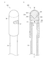
- FIG. 3A is a perspective view of the light emitting unit 30, and FIG. 3B is a cross-sectional view of the light emitting unit 30.
- the light emitting unit 30 includes a reflecting member 31 and a housing 35.
- the housing 35 has a hollow cannonball shape in which one end (tip) in the longitudinal direction bulges in a dome shape (hemispherical shape) and the other end (base end) is open.
- the tip of the tube 10 is inserted into the opening of the housing 35.
- the housing 35 is liquid-tightly fixed to the tube 10 by adhesion or the like.
- the reflective member 31 has a spherical shape and is housed in the deepest part of the lumen 36 of the housing 35.
- a flat end face 13 is formed at the tip of the tube 10.
- the end face 13 is perpendicular to the longitudinal direction of the tube 10.
- the reflective member 31 faces the end face 13 and is separated from the end face 13.
- the center of the reflective member 31 is located on the central axis of the tube 10.
- the outer diameter of the reflective member 31 is not limited, but is preferably the same as or slightly larger than the outer diameter of the tube 10. The light emitted from the end surface 13 that has passed through the tube 10 is reflected by the spherical surface 32 of the reflecting member 31 and passes through the housing 35.
- the housing 35 is provided with a hole (side hole) 37 that penetrates the housing 35 in the radial direction.
- the "radial direction” means the direction of a straight line orthogonal to the central axis of the tube 10 (which passes through the center of the reflective member 31).
- the hole 37 communicates the inner cavity 36 of the housing 35 with the outside world of the housing 35 between the end surface 13 and the reflective member 31.
- two holes 37 are provided, but the number of holes 37 may be one or three or more.
- the reflective member 31 may be made of a translucent material.
- the translucent material is not limited, but metals such as titanium, stainless steel, cobalt alloy, aluminum, and iron are preferable. Titanium, stainless steel, and cobalt alloys are excellent in corrosion resistance and biocompatibility, and can maintain good light reflection characteristics for a long period of time. Of these, titanium is preferable. Stainless steel, aluminum and iron are inexpensive. Since titanium, aluminum and the like are non-magnetic materials or low magnetic materials, they are not easily attracted during MRI inspection.
- the spherical surface 32 of the reflecting member 31 preferably has a gloss so as to function as a reflecting surface that reflects the light emitted from the end surface 13, and is particularly preferably mirror-finished.
- the reflective member 31 can also function as a weight to facilitate insertion of the tube 10 into the gastrointestinal tract.
- a weight different from the reflective member 31 may be housed in the housing 35.
- another weight is arranged on the side opposite to the end face 31 with respect to the reflective member 31.
- the reflective member 31 may be made of a translucent material. Even if it is a translucent material, it can be used as a reflecting member 31 as long as it can reflect at least a part of the light emitted from the end face 13.
- the translucent material may be plastic, glass or the like. Since plastic and glass are low electric conductors, they do not cause burns due to heat generation during MRI examination.
- the surface of the translucent material may be subjected to a process (reflection process) for reflecting light.
- the reflection processing is not limited, and examples thereof include various coatings, satin finish processing, metal deposition, and mirror surface processing.
- the reflective member 31 may be a mirror.
- a part of the light incident on the reflecting member 31 may be reflected on the surface of the reflecting member 31, and the remaining light may be incident on the reflecting member 31.
- the light may be refracted when it enters the reflecting member 31 and when it is emitted from the reflecting member 31. That is, the reflective member 31 may also function as a refracting member (see the second embodiment described later).
- the material of the housing 35 is not limited, but is preferably provided with translucency and flexibility, and for example, resins such as polyurethane, polyethylene, silicone, acrylic, and polypropylene can be used.
- the material of the tube 10 is not limited, but is preferably provided with flexibility and translucency, and for example, resins such as polyurethane, acrylic, silicone, polyethylene, styrene elastomer, and polybutadiene can be used.
- the portion where the light incident from the end surface 12 of the base end constitutes the thickness of the tube 10 (between the inner surface and the outer surface of the tube 10), hereinafter referred to as “tube 10”. It is emitted from the end face 13 (see FIG. 3B) of the tip through the "thick portion"), and the light emitting portion 30 emits light.
- the light emitting portion 30 emits light.
- the means for reducing the leakage light is not limited, but for example, (1) smoothing the outer surface of the tube 10, (2) covering the outer surface of the tube 10 with a coating material having a refractive index lower than that of the tube 10 (3).
- a metal vapor deposition layer such as silver or aluminum is provided on the outer surface of the tube 10, and (4) the tube 10 has a two-layer structure consisting of an inner layer having a high refractive index and an outer layer having a low refractive index. Alternatively, a combination of two or more can be adopted.
- the surface roughness Ra of the outer surface of the tube 10 is preferably 1.2 ⁇ m or less, more preferably 1.0 ⁇ m or less, and particularly preferably 0.4 ⁇ m or less.
- the method for smoothing the outer surface of the tube 10 is not limited, and for example, when the resin material of the tube 10 is extruded from the base, a method of setting the base temperature higher than usual can be adopted.
- the coating material covering the outer surface of the tube 10 depends on the material of the tube 10, and examples thereof include silicone oil, fluorine, and a UV curable low refractive index material. Since these have a lower refractive index than the resin material constituting the tube 10, the light emitted from the inside of the tube 10 to the coating material layer is reduced.
- the method of covering the outer surface of the tube 10 with fluorine is not limited, and examples thereof include a method of applying liquid fluorine to the outer surface of the tube 10 and a method of spraying fluorine gas on the outer surface of the tube 10.
- the tube 10 having a two-layer structure is formed by co-extruding two types of materials having different refractive indexes so that the high refractive index material is the inner layer and the low refractive index material is the outer layer.
- the tube 10 may have a three-layer structure including an inner layer and an outer layer having a low refractive index and an intermediate layer having a high refractive index between them.
- the tube 10 may have an additional multi-layer structure (eg, a five-layer structure). In either case, the light passes through the high refractive index layer.
- the end faces 12 and 13 are preferably smooth, and specifically, the surface roughness Ra of the end faces 12 and 13 is 1.2 ⁇ m or less, further 1.0 ⁇ m or less, and particularly 0.4 ⁇ m or less. Is preferable.
- Such smooth end faces 12 and 13 can be obtained, for example, by polishing the end faces 12 and 13.
- the light source device 50 includes a light source (not shown) that emits light.
- the light is preferably visible light or near-infrared light, and the wavelength of the light is not limited, but is preferably 360 nm or more, more preferably 630 nm or more, and preferably 3000 nm or less, further preferably 780 nm or less. ..
- Light having a wavelength in this range has high transmittance for the human body, is minimally invasive to the human body, and is highly safe. Since the visible light can be observed with the naked eye, the position of the light emitting unit 30 can be easily confirmed.
- Near-infrared light is more translucent than visible light and can be observed through a dedicated camera such as an infrared camera.
- the light source device 50 includes a socket (insertion port) 51 to which the connector 20 can be attached and detached.
- the light source is arranged so as to face the end surface 12 of the tube 10 when the connector 20 is connected to the socket 51.
- the light source may include a lens so that light can be efficiently incident on the end face 12.
- the socket 51 may include a switch (not shown) that turns on / off the light emission of the light source in conjunction with the attachment / detachment of the connector 20 to the socket 51. This is advantageous in ensuring that the light emitted from the light source device 50 does not enter the eyes of the operator or patient when the connector 20 is not connected.
- the light source device 50 may include a plurality of sockets 51, and in this case, each of the plurality of sockets 51 may include a light source that emits light having different wavelengths from each other.
- the first socket may include a light source that emits light having a wavelength of 630 nm
- the second socket may include a light source that emits light having a wavelength of 780 nm.
- the power source of the light source device 50 may be either a commercial power source or a battery (including a storage battery). When a battery is used as a power source, the portability of the light source device 50 can be improved, the size and weight can be easily reduced.
- the connector 20 When the connector 20 is connected to the light source device 50, the light emitting unit 30 emits light. The light from the light emitting unit 30 passes through the human body. The surgeon can confirm the position of the light emitting portion 30 from the light emitting position on the body surface of the patient 90. Light can be observed with the naked eye depending on its wavelength. If necessary, the light emitting position may be confirmed by taking a picture with an infrared camera.
- the connector 20 may be connected to the light source device 50 before the tube 10 is inserted into the patient 90, or may be connected to the light source device 50 when the light emitting unit 30 is considered to have reached the stomach.
- the tube 10 in which the stylet is inserted into the flow path 11 in advance may be inserted into the patient 90.
- the base end of the stylet can be derived from the connector 20. In this case, after pulling out the stylet from the tube 10, the connector 20 is connected to the light source device 50.
- the tube 10 in which the optical fiber is inserted into the flow path 11 so that the tip thereof reaches the light emitting portion 30 may be inserted into the patient 90.
- the tip of the optical fiber is also made to emit light in addition to the light emitting unit 30. Since the luminous flux from the light emitting unit 30 increases, the position of the light emitting unit 30 can be confirmed more accurately. After confirming that the tip of the tube 10 has reached the stomach, the optical fiber is pulled out from the tube 10.
- the flexural modulus and strength of the tube 10 are increased as compared with the case of the tube 10 alone, so that the insertability of the tube 10 into the human body is improved.
- the stylet and optical fiber preferably have a flexural modulus higher than that of the tube 10. Stylets and optical fibers having a flexural modulus higher than that of the tube 10 are more assembling to the tube 10 than those having a flexural modulus lower than that of the tube 10.
- X-ray fluoroscopy may be used in combination to confirm the position of the tube 10 more accurately. It is known that the halide can be confirmed under fluoroscopy.
- the halide can be included in the tube 10.
- the tube 10 is X-rayed by a method such as coating the outer surface of the tube 10 with a halide, kneading the halide into the material constituting the tube 10, or polymerizing the halide on the resin constituting the tube 10. It can be provided with line contrast.
- the optical fiber When the optical fiber is inserted into the tube 10, the optical fiber may be impregnated with a halogen substance by the same method as described above to provide the optical fiber with X-ray contrast.
- the stylet contains fine metal wires and has X-ray contrast. Therefore, when the stylet is inserted into the tube 10, it is not necessary to provide the tube 10 with X-ray contrast.
- the connector 20 After confirming that the tip of the tube 10 (that is, the light emitting portion 30) has reached the stomach, the connector 20 is connected to a connector (female connector) provided at the downstream end of the tube that conveys the nutrient (for example, patent). See FIG. 16A in Document 3).
- the nutritional supplement is administered to the patient through the flow path 11 of the tube 10 and through the hole 37 of the housing 35.
- Tube 10 is placed in patient 90 for several days. During this time, the light emitting unit 30 may move due to the tube 10 curling up. Therefore, at predetermined time intervals (for example, immediately before the nutritional supplement is administered to the patient 90), the connector 20 is connected to the light source device 50, the light emitting unit 30 is made to emit light, and the position is confirmed.
- the light emitting unit 30 provided at the tip of the tube 10 is made to emit light, and the light from the light emitting unit 30 is observed through the body of the patient 90. Therefore, the position of the tip of the tube 10 can be detected easily and accurately.
- the light emitted from the light emitting unit 30 is highly safe, unlike X-rays. Since the reflecting member 31 reflects the light from the end face 13 in various directions, the light from the light emitting unit 30 can be observed from the body surface of the patient 90 regardless of the direction of the light emitting unit 30.
- Patent Document 1 it is necessary to insert an optical fiber into the tube in order to confirm the position of the tip of the tube. After inserting the tube 10 into the patient and pulling out the optical fiber, it is necessary to reinsert the optical fiber into the tube in order to reconfirm the position of the tube tip. This can lead to accidents where the optical fiber penetrates the tube and damages the gastrointestinal wall.
- the tube 10 itself serves as a light transmission path, and a light emitting unit 30 is provided at the tip of the tube 10.
- the optical fiber essential in Patent Document 1 is not required in the first embodiment. Therefore, in the first embodiment, the above-mentioned accident that may occur in Patent Document 1 cannot occur. After inserting the tube 10 into the patient 90, the position of the tip of the tube 10 can be confirmed at any time.
- the system 1 of the first embodiment is excellent in safety.
- the system 1 of the first embodiment since the tube 10 itself functions as a light guide member, a light guide member such as an optical fiber is not required separately from the tube 10. Therefore, the system 1 of the first embodiment has a simple configuration and is inexpensive.
- the light emitting unit 30 includes a spherical reflecting member 31, and the light emitted from the end face 13 is reflected by the spherical surface 32 of the reflecting member 31.
- the reflective member of the present invention is not limited to this.
- the light emitting unit 30a may include a reflecting member 31a having a quadrangular pyramid surface 32a as a reflecting surface.
- the quadrangular pyramid surface 32a is arranged coaxially with the tube 10 so as to be separated from and opposed to the end surface 13.
- the light emitted from the end surface 13 is reflected by the quadrangular pyramid surface 32a and passes through the housing 35.
- the reflecting member 31a may have an arbitrary pyramid surface (preferably a regular pyramid surface) such as a triangular pyramid surface, a pentagonal pyramid surface, or the like, instead of the quadrangular pyramid surface 32a.
- the light emitting unit 30b may include a reflecting member 31b having a conical surface 32b as a reflecting surface.
- the conical surface 32b is arranged coaxially with the tube 10 so as to be separated from and opposed to the end surface 13.
- the light emitted from the end surface 13 is reflected by the conical surface 32b and passes through the housing 35.
- the reflective member 31b includes a flat surface 33b on the opposite side of the conical surface 32b, and a cylindrical surface 34b connecting the conical surface 32b and the flat surface 33b.
- Such a reflective member 31b can be easily manufactured by cutting a metal material (for example, lathe cutting).
- the reflective member may have any convex curved surface other than the spherical surface 32 and the convex cone surfaces 32a and 32b as a reflective surface on the side facing the end surface 13.
- the reflective surface of the reflective member does not have to be a convex surface, but may be a concave surface.
- the reflective member does not have to have a lump shape as a whole, and may have, for example, a ring shape facing the end face 13.
- the ring-shaped reflective member may be separated from the end face 13 or may be in contact with the end face 13 (see, for example, FIG. 6A described later).
- the nutrient spilled from the tip of the tube 10 may be configured to pass through the central opening of the ring-shaped reflective member.
- the housing 35 itself may have a function as a reflective member.
- the housing 35 is provided with a surface facing the end surface 13 as a reflecting surface.
- the light emitted from the end surface 13 is reflected by the reflecting surface of the housing 35.
- the reflecting surface may have any shape such as a spherical surface, a conical surface, and a ring shape.
- the reflecting surface is not limited to a convex surface, and may be a concave surface.
- the reflecting surface may be separated from the end surface 13 or may be in contact with the end surface 13.
- a part of the light incident on the reflecting surface of the housing 35 may be incident on the reflecting surface and emitted from the outer surface of the housing 35. Light may be refracted when it enters the housing 35 and when it exits the housing 35. That is, the housing 35 may function as a refracting member (see the second embodiment described later) in addition to the reflecting member.
- a metal vapor deposition layer or various coating layers may be provided on the reflective surface of the housing 35.
- the reflective member may be provided in direct contact with the tube 10.
- a reflective member is referred to as a "direct contact type reflective member" in the present invention.
- the light emitting portion 30c may include a direct contact type reflective member 31c provided on the end surface 13 of the tube 10.
- the light emitting unit 30d may include a direct contact type reflective member 31d provided in a region near the end surface 13 of the inner surface of the tube 10.
- the light emitting portion 30e may include a direct contact reflective member 31e provided in a region slightly distant from the end surface 13 of the inner surface of the tube 10.
- the direct contact type reflective member is not limited, but a metal vapor deposition layer and various coating layers can be exemplified, and a metal vapor deposition layer is particularly preferable.
- a reflective member created as a member separate from the tube 10 may be fixed to the tube 10 to form a direct contact type reflective member. Light enters the contact-type reflective member directly from the thick portion of the tube 10, is reflected by the reflective member, passes through the thick portion of the tube 10 again, and is emitted from the tube 10 (for example, the outer surface of the tube 10).
- the light emitting portion including the direct contact type reflecting member has a simple structure, and it is easy to provide the light emitting portion in the tube. Further, it is not necessary for the light emitting unit to include the housing 35.
- the direct contact type reflective member may be provided on the outer surface of the tube 10.
- the light emitting unit emits more light along a substantially radial direction rather than a longitudinal direction of the tube 10.
- a conical chamfer 13d is formed at the opening end defining the opening at the end surface 13 of the tube 10, and a reflective member 31d is also provided at the chamfer 13d.
- the light incident on the chamfer 13d can be reflected outward in the radial direction.
- the amount of light emitted from the end face 13 substantially along the longitudinal direction of the tube 10 is relatively small.
- the reflective member 31e is provided away from the end face 13. Most of the light is reflected by the reflecting member 31e and emitted from the tube 10 along a substantially radial direction. There is little light reaching the end face 13. Therefore, the amount of light emitted from the end face 13 substantially along the longitudinal direction of the tube 10 is relatively small.
- a low refractive index coating material, a metal vapor deposition layer, a low refractive index material layer, etc. provided on the tube 10 to reduce leakage light in order to enhance the emission of light from the tube 10 (hereinafter, these are collectively referred to).
- the “leakage light prevention layer”) may be removed in the region where light is emitted, and in addition to or instead of this, a fine unevenness is provided in the region where light is emitted on the outer surface of the tube 10. You may.
- the "fine unevenness” may be an irregular unevenness such as a pear ground, or a regular unevenness such as a knurled surface or a bellows shape. The fine irregularities also have a diffusing action that causes light to be emitted from the tube 10 in various directions.
- FIG. 7A is a perspective view of the light emitting unit 230 of the second embodiment.
- FIG. 7B is a cross-sectional view of the light emitting unit 230.
- the light emitting unit 230 of the second embodiment includes a refraction member 231 instead of the reflection member 31 (see FIG. 3B) of the first embodiment.
- the refraction member 231 is configured by combining a first prism 233 and a second prism 237 having different refractive indexes.
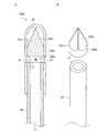
- FIG. 8A is an exploded perspective view seen from the front end side of the light emitting unit 230
- FIG. 8B is an exploded perspective view seen from the base end side of the light emitting unit 230
- the housing 35 (see FIGS. 7A and 7B) is not shown.
- the first prism 233 is a cylindrical surface that connects a concave conical surface 234 facing the second prism 237, a flat surface 235 facing the tube 10, and an outer peripheral edge of the concave conical surface 234 and an outer peripheral edge of the flat surface 235. 236 and.
- the second prism 237 includes a convex conical surface 238 facing the first prism 233 and a convex curved surface (spherical surface) 239 on the opposite side of the first prism 233.
- the concave conical surface 234 has a shape obtained by cutting a regular square pyramid surface with a cylindrical surface 236 coaxial with the regular square conical surface.
- the convex conical surface 238 has the same geometric shape as the concave conical surface 234. As shown in FIG. 7B, the first prism 233 and the second prism 237 are joined and combined so that the four side surfaces of the concave conical surface 234 and the four side surfaces of the convex conical surface 238 are in surface contact with each other. ..
- the flat surface 235 of the first prism 233 is parallel to and separated from the end surface 13 of the tube 10.
- the cylindrical surface 236 of the first prism 233 and the convex curved surface 239 of the second prism 237 are in close contact with the inner surface of the housing 35.
- the first and second prisms 233 and 237 are arranged coaxially with the tube 10.
- the outer diameters of the first and second prisms 233 and 237 are not limited, but are preferably the same as or slightly larger than the outer diameter of the tube 10.
- the first prism 233 and the second prism 237 are made of a hard material having translucency.
- the materials of the first and second prisms 233 and 237 are not limited, but materials generally used as optical materials are preferable, and specifically, glass, polymethylmethacrylate resin (PMMA), polystyrene, and the like. Resin materials such as polycarbonate and polyolefin are preferable.
- the first prism 233 and the second prism 237 are made of materials having different refractive indexes.
- the light that has passed through the tube 10 and emitted from the end surface 13 is incident on the flat surface 235, and some of the light passes through the joint surface between the concave conical surface 234 and the convex conical surface 238, the convex curved surface 239, and the housing 35 in this order. Another part of the light passes through the cylindrical surface 236 and the housing 35 in sequence.
- Light is refracted as it passes through a boundary surface (refractive surface) where the refractive index changes, such as a flat surface 235, a joint surface between a concave conical surface 234 and a convex conical surface 238, a convex curved surface 239, and a cylindrical surface 236.
- the refracting member 231 refracts the light from the end face 13 in various directions, the light from the light emitting unit 230 is emitted from the body surface of the patient 90 regardless of the orientation of the light emitting unit 230, as in the reflection member 31 of the first embodiment. It can be observed from.
- the shape of the joint surface (concave conical surface 234 and convex conical surface 238) between the first prism 233 and the second prism 237 is a part of the regular square pyramid surface. Not limited.
- the shape of the joint surface between the first prism 233 and the second prism 237 may be a part of any regular polygonal pyramid surface, or may be a conical surface.
- the shape of the joint surface between the first prism 233 and the second prism 237 is not limited to the conical surface, and may be a spherical surface or an arbitrary curved surface.
- the first prism 233 may be provided with a convex surface
- the second prism 237 may be provided with a concave surface to be joined to the convex surface.
- Part or all of the light incident on the refracting surface may be reflected by the joint surface.
- the refracting member may be composed of three or more prisms.
- the refracting member may be composed of a single prism.
- the refraction member may be composed of only the second prism 237. In this case, the light emitted from the end surface 13 is refracted when passing through the convex cone surface 238 and the convex curved surface 239.
- the second prism 237 may be integrated with the housing 35 using the same material as the housing 35.
- the first prism 233 may be present or may be omitted.
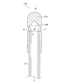
- FIG. 9A is a cross-sectional view of another light emitting unit 230a of the second embodiment.
- the light emitting unit 230a includes a refracting member 231a composed of a single prism.
- FIG. 9B is an exploded perspective view seen from the tip end side of the light emitting unit 230a. In FIG. 9B, the housing 35 (see FIG. 9A) is not shown.
- the refracting member (prism) 231a has a flat surface 235a facing the tube 10, a convex conical surface 234a on the opposite side of the flat surface 235a, and an outer peripheral edge of the flat surface 235a and an outer peripheral edge of the convex cone surface 234a. It is provided with a cylindrical surface 236a to be connected.
- the convex cone surface 234a has a shape obtained by cutting a regular square cone surface with a cylindrical surface 236a coaxial with the regular square cone surface. As shown in FIG. 9A, the flat surface 235a is parallel to and separated from the end surface 13 of the tube 10. The cylindrical surface 236a is in close contact with the inner surface of the housing 35. The refracting member 231a is arranged coaxially with the tube 10. The light emitted from the end surface 13 enters the flat surface 235a, some light passes through the convex cone surface 234a and the housing 35 in order, and another part of the light passes through the cylindrical surface 236a and the housing 35 in order. ..
- the convex cone surface 234a may be any pyramid surface or conical surface.
- FIG. 10 is a cross-sectional view of still another light emitting unit 230b of the second embodiment.
- a refraction member (prism) 231b made of the same material as the housing 35 is integrated with the housing 35. That is, a concave conical surface 234b is provided on the inner surface of the housing 35.
- the concave conical surface 234b has a shape obtained by cutting a regular square conical surface with a cylindrical surface (inner peripheral surface of the housing 35) coaxial with the regular square conical surface.
- the concave conical surface 234b is arranged coaxially with the tube 10 so as to be separated from and opposed to the end surface 13.
- the light emitted from the end surface 13 is refracted when it enters the concave conical surface 234b, passes through the refracting member 231b, and is emitted from the outer surface of the housing 35.
- the concave cone surface 234b may be any pyramid surface or conical surface.
- the shape of the refracting surface of the refracting member is arbitrary, such as a convex surface (convex curved surface or convex conical surface), a concave surface (concave curved surface or concave conical surface), and a flat surface.
- the refracting surface may be provided with fine irregularities as described in the first embodiment.
- the second embodiment is the same as the first embodiment except for the above.
- the description of the first embodiment also applies to the second embodiment.
- the third embodiment is different from the first and second embodiments in terms of the light emitting unit.
- the light emitting portion of the third embodiment includes a tip of a tube 10 formed so that light is refracted when emitted from the tube 10 and emitted in various directions.
- FIG. 11A is a side view of the light emitting unit 330 of the third embodiment
- FIG. 11B is a perspective view of the light emitting unit 330.
- the light emitting unit 330 does not include the reflection members 31, 31a to 31e of the first embodiment and the refraction members 231,231a, 231b of the second embodiment.
- the light emitting unit 330 includes four wedge-shaped notches 331 formed at the tip of the tube 10.
- the four notches 331 are arranged adjacent to each other in the circumferential direction of the tube 10 at equal intervals.
- Each notch 331 is composed of a first surface 331a parallel to the longitudinal direction of the tube 10 and a second surface 331b inclined with respect to the first surface 331a. At the deepest part of the notch 331, the first surface 331a and the second surface 331b are connected.
- the light that has passed through the tube 10 is refracted when it is emitted from the first surface 331a and the second surface 331b. Since the first and second surfaces 331a and 331b are arranged at equal angular intervals in the circumferential direction of the tube 10, the light emitted from each of the first and second surfaces 331a and 331b travels in various directions. Similar to the first and second embodiments, the light from the light emitting unit 330 can be observed from the body surface of the patient 90 regardless of the orientation of the light emitting unit 330.
- the light emitting unit 330 may include a housing similar to the housing 35 of the first and second embodiments.
- the tip of the tube 10 in which the notch 331 is formed is housed in the housing.
- the housing may include a weight to facilitate insertion of the tube 10 into the gastrointestinal tract.
- the weight is arranged apart from the notch 331 in the longitudinal direction of the tube 10.
- the shape of the notch 331 is not limited to the above-mentioned substantially right triangle, and may be any triangle such as an isosceles triangle. Alternatively, the notch 331 may be any polygon (for example, trapezoid) other than a triangle, or any curve. Also, the number of notches 331 is not limited to the above embodiment. The notches 331 may not be arranged at equal intervals in the circumferential direction.
- the light emitting unit 330 includes a plurality of notches 331, but the present invention is not limited to this.
- the tip of the tube 10 may be provided with a shape that refracts the light so that the light that has passed through the tube 10 is emitted obliquely with respect to the longitudinal direction of the tube 10.
- the end face of the tip of the tube 10 may be a conical surface whose inner diameter increases toward the tip or a conical surface whose outer diameter decreases toward the tip. In this case as well, the light can be refracted in various directions and emitted.
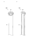
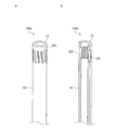
- FIG. 12A is a perspective view of another light emitting unit 330a according to the third embodiment.
- FIG. 12B is a cross-sectional perspective view of the light emitting unit 330a.
- the tip portion of the tube 10 is divided into a plurality of branch portions 332 by a plurality of notches along the longitudinal direction of the tube 10.
- the plurality of branch portions 332 are curved in a flare shape toward the outer side in the radial direction.
- the bifurcation portions 332 adjacent to each other in the circumferential direction are separated from each other.
- the light that has passed through the tube 10 is emitted from the side surface and the tip surface of each branch portion 332. Light is refracted as it exits each surface of the branch 332.
- the light emitted from each surface of each branch portion 332 travels in various directions. Regardless of the orientation of the light emitting unit 330a, the light from the light emitting unit 330a can be observed from the body surface of the patient 90.
- the light leakage prevention layer provided on the tube 10 may be removed.
- FIG. 13A is a perspective view of still another light emitting unit 330b of the third embodiment.
- FIG. 13B is a cross-sectional perspective view of the light emitting unit 330b.
- the tip portion of the tube 10 is curved inward in the radial direction.
- the end surface 13 at the tip of the tube 10 forms a substantially concave conical surface.
- the light that has passed through the tube 10 is emitted from the end face 13.
- the light is refracted as it exits the end face 13. Since the end face 13 is curved in a substantially concave conical surface shape, the light emitted from the end face 13 is once converged and then diverged like the light emitted from the convex lens. Therefore, the light from the light emitting unit 330b can be observed from the body surface of the patient 90 regardless of the orientation of the light emitting unit 330b.
- FIG. 14A is a perspective view of still another light emitting unit 330c of the third embodiment.
- FIG. 14B is a cross-sectional perspective view of the light emitting unit 330c.
- a plurality of slot-shaped holes 333 that penetrate the tube 10 in the radial direction are formed in the vicinity of the tip of the tube 10. Most of the light passing through the tube 10 is emitted from the side surface of the hole 333 (the surface defining the hole 333 and connecting the inner surface and the outer surface of the tube 10) before reaching the end surface 13. Light is refracted as it exits the sides. Since the plurality of holes 333 are arranged at substantially equal intervals in the circumferential direction, the light emitted from the side surface of each hole 333 travels in various directions.
- the amount of light emitted from the end face 13 substantially along the longitudinal direction of the tube 10 is relatively small. Regardless of the orientation of the light emitting unit 330c, the light from the light emitting unit 330c can be observed from the body surface of the patient 90.
- the longitudinal direction of the hole 333 may be parallel to the longitudinal direction of the tube 10, but is preferably slightly inclined with respect to the longitudinal direction of the tube 10, as shown in FIGS. 14A and 14B. This is advantageous for diffusing and emitting light over a wide range from the light emitting unit 330c.
- the number of holes 333 is arbitrary.
- FIG. 15A is a perspective view of still another light emitting unit 330d of the third embodiment.
- FIG. 15B is a cross-sectional perspective view of the light emitting unit 330d.
- Near the tip of the tube 10 one or more (two in this example) holes 334 having a substantially elliptical shape (or a substantially circular shape) penetrating the tube 10 in the radial direction are formed. A part of the light passing through the tube 10 is emitted from the side surface of the hole 334 (the surface defining the hole 334 and connecting the inner surface and the outer surface of the tube 10) before reaching the end surface 13. Light is refracted as it exits the sides.
- each hole 334 Since a plurality of holes 334 are arranged discretely in the circumferential direction and the side surface of each hole 334 forms a substantially elliptical (or substantially circular) closed curved surface, the light emitted from the side surface of each hole 334 is emitted. , Go in various directions. The amount of light emitted from the end face 13 substantially along the longitudinal direction of the tube 10 is relatively small. Regardless of the orientation of the light emitting unit 330d, the light from the light emitting unit 330d can be observed from the body surface of the patient 90.
- the number of holes 334 is arbitrary, but it is preferably large, and specifically, it is preferably four or more. As the number of holes 334 increases, light can be diffused and emitted from the light emitting unit 330d in a wider range.
- the shapes of the holes 333 and 334 are arbitrary, for example, elliptical, circular, various polygons (triangle, quadrangle, pentagon, etc.), arc, "V", and the like. May be good.
- the number of holes 333 and 334 is arbitrary, does not have to be plural, and may be one.
- the arrangement of the holes 333 and 334 is also arbitrary. When a plurality of holes 333 and 334 are provided, they may be provided at substantially equal intervals in the circumferential direction, or may not be provided at substantially equal intervals in the circumferential direction.
- a row of a plurality of holes 333, 334 arranged along the circumferential direction of the tube 10 may be provided at a plurality of positions different in the longitudinal direction of the tube 10.
- the light emitting portions 330c and 330d may have a recess that does not penetrate the tube 10 instead of the holes 333 and 334 that penetrate the tube 10.
- the recess may be provided on either the inner surface or the outer surface of the tube 10. Light is refracted as it exits the surface defining the recess.
- a high refractive index layer (a layer having a higher refractive index than the material of the tube 10) or the first embodiment in the end surface 13 of the tip of the tube 10 and / or the region near the tip of the inner surface and / or the outer surface of the tube 10.
- the fine unevenness described in the above may be provided.
- the light leakage prevention layer may be removed in a region near the tip of the inner surface and / or outer surface of the tube 10. Two or more of the addition of the high refractive index layer, the addition of fine irregularities, and the removal of the light leakage prevention layer may be combined. Light is refracted and emitted from the region (light emitting region) where these treatments have been applied. The position where the light emitting region is provided is arbitrary.
- the light emitting region is provided slightly away from the end face 13 of the tube 10, the light reaching the end face 13 of the tube 10 is reduced. It is advantageous for emitting light in various directions.
- the light emitting units 330a to 330d may have the same housing as the housing 35 of the first and second embodiments.
- the tip portion of the tube 10 configured to refract and emit light is housed in a housing.
- the housing may include a weight to facilitate insertion of the tube 10 into the gastrointestinal tract.
- the weight is arranged apart from the tip of the tube 10 in the longitudinal direction of the tube 10.
- the light emitting unit of the third embodiment includes a configuration provided in the tube itself so that light is emitted in various directions including the radial direction.
- the light emitting unit of the third embodiment does not need to include the reflecting member of the first embodiment or the refracting member of the second embodiment. Therefore, the number of members constituting the light emitting unit is small, and the configuration of the light emitting unit is simple. Further, the light loss that can occur due to the tube and the reflecting member or the refracting member being separated from each other does not occur in the third embodiment.
- the light emitting portion of the third embodiment may be combined with the reflecting member of the first embodiment or the refracting member of the second embodiment.
- the third embodiment is the same as the first embodiment except for the above.
- the description of the first embodiment also applies to the third embodiment.
- the present invention was applied to oral and nasal tube feeding in the above-described first to third embodiments, the present invention can be applied to any other field in which a tube is inserted into the human body.
- the present invention can be applied when a catheter (tube) is inserted into an artery or a vein.
- the liquid flowing through the tube is optional, such as a nutrient, a drug, a contrast medium, or blood.
- the configuration of the connector, light emitting part, tube, etc. can be changed according to the field of application.
- the connector provided at the base end of the tube is not limited to the male connector 20 shown in the above-described first to third embodiments.
- the connector may not be provided with the female screw 24, and may not be provided with the outer cylinder 23.
- the shape of the male member 21 can be changed arbitrarily.
- the connector may be a female connector.
- the present invention can be widely used in the medical field.
- the present invention can be preferably used in tube feeding, particularly oral and nasal tube feeding.
Landscapes
- Health & Medical Sciences (AREA)
- Life Sciences & Earth Sciences (AREA)
- Animal Behavior & Ethology (AREA)
- General Health & Medical Sciences (AREA)
- Public Health (AREA)
- Veterinary Medicine (AREA)
- Pulmonology (AREA)
- Heart & Thoracic Surgery (AREA)
- Engineering & Computer Science (AREA)
- Biomedical Technology (AREA)
- Hematology (AREA)
- Anesthesiology (AREA)
- Biophysics (AREA)
- Surgery (AREA)
- Otolaryngology (AREA)
- Nuclear Medicine, Radiotherapy & Molecular Imaging (AREA)
- Oral & Maxillofacial Surgery (AREA)
- Pathology (AREA)
- Medical Informatics (AREA)
- Molecular Biology (AREA)
- Media Introduction/Drainage Providing Device (AREA)
- Infusion, Injection, And Reservoir Apparatuses (AREA)
- Light Guides In General And Applications Therefor (AREA)
- Medical Preparation Storing Or Oral Administration Devices (AREA)
Abstract
Description
図1は、経口・経鼻経管栄養に適用した本発明の実施形態1にかかるシステム1の概略構成を示す。経口・経鼻チューブ(以下、単にチューブという)10が患者90の鼻腔から挿入され、その先端は胃91に達している。チューブ10は、湾曲変形が可能な可撓性を有している。チューブ10は、その全長にわたって連続する流路11(後述する図2B、図3B参照)が形成された中空の筒状物である。栄養剤等の液体は、流路11を通って患者の胃91に投与される。チューブ10の基端にはコネクタ20が設けられている。チューブ10の先端には、発光部30が設けられている。コネクタ20は、光源装置50に繰り返し接続及び分離が可能である。コネクタ20を光源装置50に接続したとき、光源装置50に内蔵された光源(図示せず)からの光は、チューブ10を通過して発光部30から発射される。発光部30からの光は患者90の身体を透過して体表面を光らせる。術者は、患者90の体表面での発光位置からチューブ10の先端の位置を確認することができる。
本実施形態2は、発光部に関して実施形態1と異なる。図7Aは、本実施形態2の発光部230の斜視図である。図7Bは、発光部230の断面図である。図7Bに示されているように、本実施形態2の発光部230は、実施形態1の反射部材31(図3B参照)に代えて、屈折部材231を備える。屈折部材231は、屈折率が異なる第1プリズム233と第2プリズム237とが組み合わされて構成される。
本実施形態3は、発光部に関して実施形態1,2と異なる。本実施形態3の発光部は、光がチューブ10から出射する際に屈折され様々な方向に出射するように形成されたチューブ10の先端を含む。
10 チューブ
11 流路
12 チューブの基端の端面
13 チューブの先端の端面
20 コネクタ
21 オス部材
23 外筒
24 雌ネジ
30,30a~30e,230,230a,230b,330,330a~330d 発光部
31,31a~31e 反射部材
32 球面
32a,32b 錐面
35 ハウジング
37 ハウジングの孔
231,231a,231b 屈折部材
333,334 チューブを貫通する孔
50 光源装置
Claims (18)
- 患者に挿入されるチューブの先端の位置を検出するための医療用チューブの先端位置検出システムであって、
光を発射する光源装置と、
液体が通過可能な流路を有する中空のチューブと、
前記チューブの基端の端面に前記光源装置からの光が入射可能なように、前記チューブの基端に設けられたコネクタと、
前記チューブの先端に設けられた発光部とを備え、
前記光源装置からの光を前記チューブを通過させて前記発光部から発射させ、前記発光部からの光を体表面に透過させることを特徴とする医療用チューブの先端位置検出システム。 - 前記光源装置が発射する光の波長は360nm~3000nmである請求項1に記載の医療用チューブの先端位置検出システム。
- 前記コネクタは、前記チューブが挿入された筒状のオス部材と、前記オス部材を取り囲む外筒と、前記外筒の前記オス部材に対向する内周面に形成された雌ネジとを備える請求項1又は2に記載の医療用チューブの先端位置検出システム。
- 前記チューブの基端の前記端面が、前記オス部材の先端の開口に露出している請求項3に記載の医療用チューブの先端位置検出システム。
- 前記発光部は、前記チューブから出射した光を反射させる反射部材を含む請求項1~4のいずれか一項に記載の医療用チューブの先端位置検出システム。
- 前記反射部材は、前記チューブの先端の端面に対向する側に、球面または錐面を備える請求項5に記載の医療用チューブの先端位置検出システム。
- 前記反射部材はチタンからなる請求項5又は6に記載の医療用チューブの先端位置検出システム。
- 前記反射部材が前記チューブに直接接触して設けられている請求項5に記載の医療用チューブの先端位置検出システム。
- 前記反射部材が、金属蒸着層である請求項8に記載の医療用チューブの先端位置検出システム。
- 前記発光部は、前記チューブから出射した光を屈折させる屈折部材を含む請求項1~4のいずれか一項に記載の医療用チューブの先端位置検出システム。
- 前記発光部は、前記チューブを通過した光が屈折して出射するように形成された前記チューブの先端を含む請求項1~4のいずれか一項に記載の医療用チューブの先端位置検出システム。
- 前記発光部は、前記チューブを貫通する孔、または、前記チューブの内面もしくは外面に設けられた凹部を含む請求項1~4のいずれか一項に記載の医療用チューブの先端位置検出システム。
- 前記チューブを通過する光が前記チューブの外面から出射するのを防止するための漏れ光防止層が、前記チューブの外面に設けられており、
前記発光部において前記漏れ光防止層が除去されている請求項1~4,8~11のいずれか一項に記載の医療用チューブの先端位置検出システム。 - 前記発光部は、ハウジングを備え、
前記ハウジングに、前記チューブを通過した液体を外界に流出させることが可能な孔が設けられている請求項1~13のいずれか一項に記載の医療用チューブの先端位置検出システム。 - 前記発光部は、透光性を有するハウジングを備える請求項1~14のいずれか一項に記載の医療用チューブの先端位置検出システム。
- 前記チューブの外面の表面粗さRaは1.2μm以下である請求項1~15のいずれか一項に記載の医療用チューブの先端位置検出システム。
- 前記チューブの外面が、前記チューブより低屈折率の被覆材で覆われている請求項1~16のいずれか一項に記載の医療用チューブの先端位置検出システム。
- 前記チューブの前記流路に挿抜可能なスタイレット又は光ファイバーを更に備える請求項1~17のいずれか一項に記載の医療用チューブの先端位置検出システム。
Priority Applications (6)
| Application Number | Priority Date | Filing Date | Title |
|---|---|---|---|
| CN202080053707.2A CN114173741B (zh) | 2019-08-05 | 2020-08-03 | 医疗用软管的前端位置检测系统 |
| JP2021537306A JPWO2021024992A1 (ja) | 2019-08-05 | 2020-08-03 | |
| EP20850704.6A EP4011430A4 (en) | 2019-08-05 | 2020-08-03 | MEDICAL TUBE DISTAL END POSITION DETECTION SYSTEM |
| US17/632,353 US12589053B2 (en) | 2019-08-05 | 2020-08-03 | System for detecting position of distal end of medical tube |
| KR1020227006098A KR102937497B1 (ko) | 2019-08-05 | 2020-08-03 | 의료용 튜브의 선단 위치 검출 시스템 |
| JP2024202423A JP2025028912A (ja) | 2019-08-05 | 2024-11-20 | 医療用チューブの先端位置検出システム |
Applications Claiming Priority (2)
| Application Number | Priority Date | Filing Date | Title |
|---|---|---|---|
| JP2019-143894 | 2019-08-05 | ||
| JP2019143894 | 2019-08-05 |
Publications (1)
| Publication Number | Publication Date |
|---|---|
| WO2021024992A1 true WO2021024992A1 (ja) | 2021-02-11 |
Family
ID=74503820
Family Applications (1)
| Application Number | Title | Priority Date | Filing Date |
|---|---|---|---|
| PCT/JP2020/029697 Ceased WO2021024992A1 (ja) | 2019-08-05 | 2020-08-03 | 医療用チューブの先端位置検出システム |
Country Status (6)
| Country | Link |
|---|---|
| US (1) | US12589053B2 (ja) |
| EP (1) | EP4011430A4 (ja) |
| JP (2) | JPWO2021024992A1 (ja) |
| KR (1) | KR102937497B1 (ja) |
| CN (1) | CN114173741B (ja) |
| WO (1) | WO2021024992A1 (ja) |
Cited By (5)
| Publication number | Priority date | Publication date | Assignee | Title |
|---|---|---|---|---|
| WO2022168529A1 (ja) * | 2021-02-02 | 2022-08-11 | 株式会社ジェイ・エム・エス | アダプタ |
| JP2022175740A (ja) * | 2021-05-14 | 2022-11-25 | 株式会社ジェイ・エム・エス | 医療用カテーテル |
| WO2023090229A1 (ja) * | 2021-11-16 | 2023-05-25 | スタンレー電気株式会社 | 撮像装置 |
| CN116437978A (zh) * | 2020-09-09 | 2023-07-14 | 神经科学株式会社 | 医用软管、医用软管位置确认系统 |
| JP2024011567A (ja) * | 2022-07-15 | 2024-01-25 | 株式会社ジェイ・エム・エス | 医療用カテーテル |
Citations (22)
| Publication number | Priority date | Publication date | Assignee | Title |
|---|---|---|---|---|
| US3866599A (en) * | 1972-01-21 | 1975-02-18 | Univ Washington | Fiberoptic catheter |
| US4567882A (en) * | 1982-12-06 | 1986-02-04 | Vanderbilt University | Method for locating the illuminated tip of an endotracheal tube |
| DE3603782A1 (de) * | 1986-02-06 | 1987-10-15 | Hauer Gerald | Verfahren zum orten einer venenstrippersonde sowie vorrichtung zur durchfuehrung des verfahrens |
| JPH0680439U (ja) | 1993-04-28 | 1994-11-15 | 日本シャーウッド株式会社 | 経腸栄養補給用チューブ |
| JPH08215316A (ja) | 1995-02-16 | 1996-08-27 | Terumo Corp | カテーテル |
| JP2004318090A (ja) * | 2003-04-01 | 2004-11-11 | Fuji Photo Film Co Ltd | プラスチック光ファイバの製造方法及び製造装置 |
| JP2004536639A (ja) * | 2001-06-19 | 2004-12-09 | ザ・トラステイーズ・オブ・ザ・ユニバーシテイ・オブ・ペンシルベニア | 侵襲性カテーテルの配置用の光学的案内システム |
| JP2008224979A (ja) * | 2007-03-12 | 2008-09-25 | Sumitomo Electric Ind Ltd | 光照射ファイバ及び光照射ファイバの製造方法 |
| US20120215073A1 (en) | 2009-08-21 | 2012-08-23 | Sherman Audrey A | Methods and products for illuminating tissue |
| JP2013198644A (ja) | 2012-03-26 | 2013-10-03 | Panasonic Corp | 管先端位置確認装置 |
| US20130267888A1 (en) * | 2012-04-05 | 2013-10-10 | Veritas Medical, L.L.C. | Methods and apparatus to inactivate infectious agents on a catheter residing in a body cavity |
| WO2013171870A1 (ja) | 2012-05-17 | 2013-11-21 | ケミカル機器株式会社 | 経管栄養カテーテルの体内位置を確認するための装置及び方法 |
| JP2015077168A (ja) | 2013-10-15 | 2015-04-23 | ニプロ株式会社 | アブレーションデバイス |
| JP2015077336A (ja) | 2013-10-18 | 2015-04-23 | ジーニアルライト株式会社 | 生体用モニタリング装置 |
| JP2015119837A (ja) | 2013-12-24 | 2015-07-02 | 株式会社ジェイ・エム・エス | オスコネクタ |
| WO2015133119A1 (ja) | 2014-03-04 | 2015-09-11 | 学校法人久留米大学 | 先端加工された光照射用光ファイバー及びこれを用いた体内照灯装置 |
| JP2016067526A (ja) * | 2014-09-29 | 2016-05-09 | テルモ株式会社 | レーザー光照射装置 |
| US20160331646A1 (en) | 2006-04-12 | 2016-11-17 | Syripump Limited | Feeding tube position confirmation device |
| WO2017172388A1 (en) | 2016-03-28 | 2017-10-05 | Becton, Dickinson And Company | Optical fiber sensor |
| JP2018029753A (ja) | 2016-08-24 | 2018-03-01 | 株式会社ジェイ・エム・エス | コネクタ用カバー |
| JP2018089004A (ja) | 2016-11-30 | 2018-06-14 | 京セラ株式会社 | 経口栄養摂取器具、および、経口栄養摂取器具の製造方法 |
| EP3603692A1 (en) | 2016-07-25 | 2020-02-05 | Nikkiso Co., Ltd. | Light introduction device and sterilization system |
Family Cites Families (17)
| Publication number | Priority date | Publication date | Assignee | Title |
|---|---|---|---|---|
| EP0131659A1 (en) * | 1983-07-08 | 1985-01-23 | Vanderbilt University | Medical tube and method of use thereof |
| US7992573B2 (en) | 2001-06-19 | 2011-08-09 | The Trustees Of The University Of Pennsylvania | Optically guided system for precise placement of a medical catheter in a patient |
| KR20040088402A (ko) | 2003-04-01 | 2004-10-16 | 후지 샤신 필름 가부시기가이샤 | 플라스틱 광섬유 제조 방법 및 장치 |
| US20080039715A1 (en) * | 2004-11-04 | 2008-02-14 | Wilson David F | Three-dimensional optical guidance for catheter placement |
| US20080118214A1 (en) * | 2006-04-20 | 2008-05-22 | Peng Chen | Optical fiber for detecting stress and associated method |
| EP2150194B1 (en) * | 2007-04-27 | 2012-09-12 | Tyco Healthcare Group LP | System for treating hollow anatomical structures |
| WO2009108933A2 (en) * | 2008-02-28 | 2009-09-03 | Palomar Medical Technologies, Inc. | Systems and methods for treatment of soft tissue |
| US8795162B2 (en) * | 2009-11-10 | 2014-08-05 | Invuity, Inc. | Illuminated suction apparatus |
| JP2012115535A (ja) * | 2010-12-02 | 2012-06-21 | Kochi Univ | 近赤外蛍光を発する医療具及び医療具位置確認システム |
| JP5924641B2 (ja) * | 2011-10-17 | 2016-05-25 | 学校法人東京電機大学 | 医療用チューブの先端位置検出システムおよび当該システムに適用する医療用チューブ |
| WO2014138923A1 (en) * | 2013-03-15 | 2014-09-18 | Synaptive Medical (Barbados) Inc. | Insert imaging device for surgical procedures |
| EP3058888B1 (en) | 2013-10-15 | 2019-06-12 | Nipro Corporation | Ablation system and ablation device |
| JP6807012B2 (ja) * | 2016-02-19 | 2021-01-06 | 株式会社ジェイ・エム・エス | アダプタ |
| US20200061388A1 (en) * | 2016-11-28 | 2020-02-27 | The General Hospital Corporation | Systems, methods, and flexible optical waveguides for scleral crosslinking |
| US10234614B2 (en) * | 2017-01-20 | 2019-03-19 | Corning Research & Development Corporation | Light source assemblies and systems and methods with mode homogenization |
| US11666732B2 (en) | 2017-05-11 | 2023-06-06 | Takashi Mato | Catheter device |
| CN109172990B (zh) * | 2018-10-25 | 2021-04-06 | 河南大学 | 一种医疗软管路径监测及控制系统 |
-
2020
- 2020-08-03 JP JP2021537306A patent/JPWO2021024992A1/ja active Pending
- 2020-08-03 EP EP20850704.6A patent/EP4011430A4/en active Pending
- 2020-08-03 WO PCT/JP2020/029697 patent/WO2021024992A1/ja not_active Ceased
- 2020-08-03 KR KR1020227006098A patent/KR102937497B1/ko active Active
- 2020-08-03 CN CN202080053707.2A patent/CN114173741B/zh active Active
- 2020-08-03 US US17/632,353 patent/US12589053B2/en active Active
-
2024
- 2024-11-20 JP JP2024202423A patent/JP2025028912A/ja active Pending
Patent Citations (22)
| Publication number | Priority date | Publication date | Assignee | Title |
|---|---|---|---|---|
| US3866599A (en) * | 1972-01-21 | 1975-02-18 | Univ Washington | Fiberoptic catheter |
| US4567882A (en) * | 1982-12-06 | 1986-02-04 | Vanderbilt University | Method for locating the illuminated tip of an endotracheal tube |
| DE3603782A1 (de) * | 1986-02-06 | 1987-10-15 | Hauer Gerald | Verfahren zum orten einer venenstrippersonde sowie vorrichtung zur durchfuehrung des verfahrens |
| JPH0680439U (ja) | 1993-04-28 | 1994-11-15 | 日本シャーウッド株式会社 | 経腸栄養補給用チューブ |
| JPH08215316A (ja) | 1995-02-16 | 1996-08-27 | Terumo Corp | カテーテル |
| JP2004536639A (ja) * | 2001-06-19 | 2004-12-09 | ザ・トラステイーズ・オブ・ザ・ユニバーシテイ・オブ・ペンシルベニア | 侵襲性カテーテルの配置用の光学的案内システム |
| JP2004318090A (ja) * | 2003-04-01 | 2004-11-11 | Fuji Photo Film Co Ltd | プラスチック光ファイバの製造方法及び製造装置 |
| US20160331646A1 (en) | 2006-04-12 | 2016-11-17 | Syripump Limited | Feeding tube position confirmation device |
| JP2008224979A (ja) * | 2007-03-12 | 2008-09-25 | Sumitomo Electric Ind Ltd | 光照射ファイバ及び光照射ファイバの製造方法 |
| US20120215073A1 (en) | 2009-08-21 | 2012-08-23 | Sherman Audrey A | Methods and products for illuminating tissue |
| JP2013198644A (ja) | 2012-03-26 | 2013-10-03 | Panasonic Corp | 管先端位置確認装置 |
| US20130267888A1 (en) * | 2012-04-05 | 2013-10-10 | Veritas Medical, L.L.C. | Methods and apparatus to inactivate infectious agents on a catheter residing in a body cavity |
| WO2013171870A1 (ja) | 2012-05-17 | 2013-11-21 | ケミカル機器株式会社 | 経管栄養カテーテルの体内位置を確認するための装置及び方法 |
| JP2015077168A (ja) | 2013-10-15 | 2015-04-23 | ニプロ株式会社 | アブレーションデバイス |
| JP2015077336A (ja) | 2013-10-18 | 2015-04-23 | ジーニアルライト株式会社 | 生体用モニタリング装置 |
| JP2015119837A (ja) | 2013-12-24 | 2015-07-02 | 株式会社ジェイ・エム・エス | オスコネクタ |
| WO2015133119A1 (ja) | 2014-03-04 | 2015-09-11 | 学校法人久留米大学 | 先端加工された光照射用光ファイバー及びこれを用いた体内照灯装置 |
| JP2016067526A (ja) * | 2014-09-29 | 2016-05-09 | テルモ株式会社 | レーザー光照射装置 |
| WO2017172388A1 (en) | 2016-03-28 | 2017-10-05 | Becton, Dickinson And Company | Optical fiber sensor |
| EP3603692A1 (en) | 2016-07-25 | 2020-02-05 | Nikkiso Co., Ltd. | Light introduction device and sterilization system |
| JP2018029753A (ja) | 2016-08-24 | 2018-03-01 | 株式会社ジェイ・エム・エス | コネクタ用カバー |
| JP2018089004A (ja) | 2016-11-30 | 2018-06-14 | 京セラ株式会社 | 経口栄養摂取器具、および、経口栄養摂取器具の製造方法 |
Non-Patent Citations (1)
| Title |
|---|
| See also references of EP4011430A4 |
Cited By (9)
| Publication number | Priority date | Publication date | Assignee | Title |
|---|---|---|---|---|
| CN116437978A (zh) * | 2020-09-09 | 2023-07-14 | 神经科学株式会社 | 医用软管、医用软管位置确认系统 |
| EP4212199A4 (en) * | 2020-09-09 | 2024-09-18 | Neuroceuticals Inc. | Medical tube, and medical tube position detection system |
| EP4649989A3 (en) * | 2020-09-09 | 2026-01-28 | Otsuka Clinical Solutions, Inc. | Medical tube, and medical tube position detection system |
| CN116437978B (zh) * | 2020-09-09 | 2026-02-24 | 大冢临床服务株式会社 | 医用软管、医用软管位置确认系统 |
| WO2022168529A1 (ja) * | 2021-02-02 | 2022-08-11 | 株式会社ジェイ・エム・エス | アダプタ |
| JP2022175740A (ja) * | 2021-05-14 | 2022-11-25 | 株式会社ジェイ・エム・エス | 医療用カテーテル |
| JP7699337B2 (ja) | 2021-05-14 | 2025-06-27 | 株式会社ジェイ・エム・エス | 医療用カテーテル |
| WO2023090229A1 (ja) * | 2021-11-16 | 2023-05-25 | スタンレー電気株式会社 | 撮像装置 |
| JP2024011567A (ja) * | 2022-07-15 | 2024-01-25 | 株式会社ジェイ・エム・エス | 医療用カテーテル |
Also Published As
| Publication number | Publication date |
|---|---|
| CN114173741A (zh) | 2022-03-11 |
| KR20220044970A (ko) | 2022-04-12 |
| KR102937497B1 (ko) | 2026-03-10 |
| EP4011430A4 (en) | 2023-07-26 |
| JPWO2021024992A1 (ja) | 2021-02-11 |
| EP4011430A1 (en) | 2022-06-15 |
| CN114173741B (zh) | 2025-11-04 |
| US20220287917A1 (en) | 2022-09-15 |
| US12589053B2 (en) | 2026-03-31 |
| JP2025028912A (ja) | 2025-03-05 |
Similar Documents
| Publication | Publication Date | Title |
|---|---|---|
| KR102937497B1 (ko) | 의료용 튜브의 선단 위치 검출 시스템 | |
| JP6896699B2 (ja) | 画像誘導治療/診断カテーテル用マイクロ成形アナモフィック反射器レンズ | |
| US10173075B2 (en) | Light-guided ophthalmic radiation device | |
| US20240082559A1 (en) | Adapter | |
| JP6499375B2 (ja) | 放射状照明システム | |
| US12023005B2 (en) | Positioning a tube in a lumen via transillumination | |
| JPS63212343A (ja) | カテーテル | |
| US11874455B2 (en) | Light irradiation device and light irradiation system | |
| CN109938679B (zh) | 带有护套管的内窥镜 | |
| WO2020039866A1 (ja) | 涙道内挿管システム | |
| JP2015066018A (ja) | 光ガイドシステム | |
| CN218917821U (zh) | 匀光棒、照明装置及内窥镜 | |
| JP2016214373A (ja) | 光照射器システム、子宮頸部用光線力学的治療装置および照射方法 | |
| JP7620272B2 (ja) | コネクタ | |
| JP2024051066A (ja) | バルーンカテーテル | |
| US11045665B2 (en) | Light-guided ophthalmic radiation device | |
| JP7699337B2 (ja) | 医療用カテーテル | |
| CN116783529A (zh) | 适配器 | |
| WO2018221404A1 (ja) | カテーテル装置 | |
| JP7193299B2 (ja) | 画像診断用カテーテル | |
| CN209437858U (zh) | 一种用于插管的辅助装置 | |
| JP2003284678A (ja) | 医療用内視鏡 | |
| CN120417826A (zh) | 内窥镜以及内窥镜的制造方法 | |
| JPH0451211A (ja) | ファイバスコープ |
Legal Events
| Date | Code | Title | Description |
|---|---|---|---|
| 121 | Ep: the epo has been informed by wipo that ep was designated in this application |
Ref document number: 20850704 Country of ref document: EP Kind code of ref document: A1 |
|
| ENP | Entry into the national phase |
Ref document number: 2021537306 Country of ref document: JP Kind code of ref document: A |
|
| NENP | Non-entry into the national phase |
Ref country code: DE |
|
| ENP | Entry into the national phase |
Ref document number: 20227006098 Country of ref document: KR Kind code of ref document: A |
|
| ENP | Entry into the national phase |
Ref document number: 2020850704 Country of ref document: EP Effective date: 20220307 |
|
| WWG | Wipo information: grant in national office |
Ref document number: 202080053707.2 Country of ref document: CN |
|
| WWG | Wipo information: grant in national office |
Ref document number: 17632353 Country of ref document: US |