WO2021039927A1 - ガスタービンエンジン - Google Patents
ガスタービンエンジン Download PDFInfo
- Publication number
- WO2021039927A1 WO2021039927A1 PCT/JP2020/032457 JP2020032457W WO2021039927A1 WO 2021039927 A1 WO2021039927 A1 WO 2021039927A1 JP 2020032457 W JP2020032457 W JP 2020032457W WO 2021039927 A1 WO2021039927 A1 WO 2021039927A1
- Authority
- WO
- WIPO (PCT)
- Prior art keywords
- oil mist
- air
- heat exchange
- pipe
- gas turbine
- Prior art date
- Legal status (The legal status is an assumption and is not a legal conclusion. Google has not performed a legal analysis and makes no representation as to the accuracy of the status listed.)
- Ceased
Links
Images



Classifications
-
- F—MECHANICAL ENGINEERING; LIGHTING; HEATING; WEAPONS; BLASTING
- F02—COMBUSTION ENGINES; HOT-GAS OR COMBUSTION-PRODUCT ENGINE PLANTS
- F02C—GAS-TURBINE PLANTS; AIR INTAKES FOR JET-PROPULSION PLANTS; CONTROLLING FUEL SUPPLY IN AIR-BREATHING JET-PROPULSION PLANTS
- F02C7/00—Features, components parts, details or accessories, not provided for in, or of interest apart form groups F02C1/00 - F02C6/00; Air intakes for jet-propulsion plants
- F02C7/06—Arrangements of bearings; Lubricating
-
- F—MECHANICAL ENGINEERING; LIGHTING; HEATING; WEAPONS; BLASTING
- F02—COMBUSTION ENGINES; HOT-GAS OR COMBUSTION-PRODUCT ENGINE PLANTS
- F02C—GAS-TURBINE PLANTS; AIR INTAKES FOR JET-PROPULSION PLANTS; CONTROLLING FUEL SUPPLY IN AIR-BREATHING JET-PROPULSION PLANTS
- F02C6/00—Plural gas-turbine plants; Combinations of gas-turbine plants with other apparatus; Adaptations of gas-turbine plants for special use
- F02C6/04—Gas-turbine plants providing heated or pressurised working fluid for other apparatus, e.g. without mechanical power output
- F02C6/06—Gas-turbine plants providing heated or pressurised working fluid for other apparatus, e.g. without mechanical power output providing compressed gas
- F02C6/08—Gas-turbine plants providing heated or pressurised working fluid for other apparatus, e.g. without mechanical power output providing compressed gas the gas being bled from the gas-turbine compressor
-
- F—MECHANICAL ENGINEERING; LIGHTING; HEATING; WEAPONS; BLASTING
- F01—MACHINES OR ENGINES IN GENERAL; ENGINE PLANTS IN GENERAL; STEAM ENGINES
- F01D—NON-POSITIVE DISPLACEMENT MACHINES OR ENGINES, e.g. STEAM TURBINES
- F01D25/00—Component parts, details, or accessories, not provided for in, or of interest apart from, other groups
- F01D25/18—Lubricating arrangements
-
- F—MECHANICAL ENGINEERING; LIGHTING; HEATING; WEAPONS; BLASTING
- F02—COMBUSTION ENGINES; HOT-GAS OR COMBUSTION-PRODUCT ENGINE PLANTS
- F02C—GAS-TURBINE PLANTS; AIR INTAKES FOR JET-PROPULSION PLANTS; CONTROLLING FUEL SUPPLY IN AIR-BREATHING JET-PROPULSION PLANTS
- F02C7/00—Features, components parts, details or accessories, not provided for in, or of interest apart form groups F02C1/00 - F02C6/00; Air intakes for jet-propulsion plants
- F02C7/12—Cooling of plants
- F02C7/14—Cooling of plants of fluids in the plant, e.g. lubricant or fuel
-
- F—MECHANICAL ENGINEERING; LIGHTING; HEATING; WEAPONS; BLASTING
- F02—COMBUSTION ENGINES; HOT-GAS OR COMBUSTION-PRODUCT ENGINE PLANTS
- F02C—GAS-TURBINE PLANTS; AIR INTAKES FOR JET-PROPULSION PLANTS; CONTROLLING FUEL SUPPLY IN AIR-BREATHING JET-PROPULSION PLANTS
- F02C7/00—Features, components parts, details or accessories, not provided for in, or of interest apart form groups F02C1/00 - F02C6/00; Air intakes for jet-propulsion plants
- F02C7/12—Cooling of plants
- F02C7/16—Cooling of plants characterised by cooling medium
-
- F—MECHANICAL ENGINEERING; LIGHTING; HEATING; WEAPONS; BLASTING
- F02—COMBUSTION ENGINES; HOT-GAS OR COMBUSTION-PRODUCT ENGINE PLANTS
- F02C—GAS-TURBINE PLANTS; AIR INTAKES FOR JET-PROPULSION PLANTS; CONTROLLING FUEL SUPPLY IN AIR-BREATHING JET-PROPULSION PLANTS
- F02C9/00—Controlling gas-turbine plants; Controlling fuel supply in air- breathing jet-propulsion plants
- F02C9/16—Control of working fluid flow
- F02C9/18—Control of working fluid flow by bleeding, bypassing or acting on variable working fluid interconnections between turbines or compressors or their stages
-
- F—MECHANICAL ENGINEERING; LIGHTING; HEATING; WEAPONS; BLASTING
- F02—COMBUSTION ENGINES; HOT-GAS OR COMBUSTION-PRODUCT ENGINE PLANTS
- F02K—JET-PROPULSION PLANTS
- F02K3/00—Plants including a gas turbine driving a compressor or a ducted fan
- F02K3/08—Plants including a gas turbine driving a compressor or a ducted fan with supplementary heating of the working fluid; Control thereof
- F02K3/105—Heating the by-pass flow
- F02K3/115—Heating the by-pass flow by means of indirect heat exchange
-
- F—MECHANICAL ENGINEERING; LIGHTING; HEATING; WEAPONS; BLASTING
- F16—ENGINEERING ELEMENTS AND UNITS; GENERAL MEASURES FOR PRODUCING AND MAINTAINING EFFECTIVE FUNCTIONING OF MACHINES OR INSTALLATIONS; THERMAL INSULATION IN GENERAL
- F16N—LUBRICATING
- F16N7/00—Arrangements for supplying oil or unspecified lubricant from a stationary reservoir or the equivalent in or on the machine or member to be lubricated
- F16N7/30—Arrangements for supplying oil or unspecified lubricant from a stationary reservoir or the equivalent in or on the machine or member to be lubricated the oil being fed or carried along by another fluid
- F16N7/32—Mist lubrication
-
- F—MECHANICAL ENGINEERING; LIGHTING; HEATING; WEAPONS; BLASTING
- F05—INDEXING SCHEMES RELATING TO ENGINES OR PUMPS IN VARIOUS SUBCLASSES OF CLASSES F01-F04
- F05D—INDEXING SCHEME FOR ASPECTS RELATING TO NON-POSITIVE-DISPLACEMENT MACHINES OR ENGINES, GAS-TURBINES OR JET-PROPULSION PLANTS
- F05D2220/00—Application
- F05D2220/30—Application in turbines
- F05D2220/32—Application in turbines in gas turbines
-
- F—MECHANICAL ENGINEERING; LIGHTING; HEATING; WEAPONS; BLASTING
- F05—INDEXING SCHEMES RELATING TO ENGINES OR PUMPS IN VARIOUS SUBCLASSES OF CLASSES F01-F04
- F05D—INDEXING SCHEME FOR ASPECTS RELATING TO NON-POSITIVE-DISPLACEMENT MACHINES OR ENGINES, GAS-TURBINES OR JET-PROPULSION PLANTS
- F05D2240/00—Components
- F05D2240/50—Bearings
-
- F—MECHANICAL ENGINEERING; LIGHTING; HEATING; WEAPONS; BLASTING
- F05—INDEXING SCHEMES RELATING TO ENGINES OR PUMPS IN VARIOUS SUBCLASSES OF CLASSES F01-F04
- F05D—INDEXING SCHEME FOR ASPECTS RELATING TO NON-POSITIVE-DISPLACEMENT MACHINES OR ENGINES, GAS-TURBINES OR JET-PROPULSION PLANTS
- F05D2260/00—Function
- F05D2260/98—Lubrication
-
- F—MECHANICAL ENGINEERING; LIGHTING; HEATING; WEAPONS; BLASTING
- F16—ENGINEERING ELEMENTS AND UNITS; GENERAL MEASURES FOR PRODUCING AND MAINTAINING EFFECTIVE FUNCTIONING OF MACHINES OR INSTALLATIONS; THERMAL INSULATION IN GENERAL
- F16N—LUBRICATING
- F16N2210/00—Applications
- F16N2210/02—Turbines
-
- F—MECHANICAL ENGINEERING; LIGHTING; HEATING; WEAPONS; BLASTING
- F16—ENGINEERING ELEMENTS AND UNITS; GENERAL MEASURES FOR PRODUCING AND MAINTAINING EFFECTIVE FUNCTIONING OF MACHINES OR INSTALLATIONS; THERMAL INSULATION IN GENERAL
- F16N—LUBRICATING
- F16N2210/00—Applications
- F16N2210/14—Bearings
-
- Y—GENERAL TAGGING OF NEW TECHNOLOGICAL DEVELOPMENTS; GENERAL TAGGING OF CROSS-SECTIONAL TECHNOLOGIES SPANNING OVER SEVERAL SECTIONS OF THE IPC; TECHNICAL SUBJECTS COVERED BY FORMER USPC CROSS-REFERENCE ART COLLECTIONS [XRACs] AND DIGESTS
- Y02—TECHNOLOGIES OR APPLICATIONS FOR MITIGATION OR ADAPTATION AGAINST CLIMATE CHANGE
- Y02T—CLIMATE CHANGE MITIGATION TECHNOLOGIES RELATED TO TRANSPORTATION
- Y02T50/00—Aeronautics or air transport
- Y02T50/60—Efficient propulsion technologies, e.g. for aircraft
Definitions
- the present invention relates to a gas turbine engine.
- Patent Document 1 discloses a mechanism for supplying oil mist to bearings in a flying gas turbine engine.
- compressed air is introduced into the oil mist generating means from the compressor of the engine when the flying object flies.
- the oil mist generating means the oil is mist-ized by the introduced compressed air to generate oil mist.
- the generated oil mist is supplied to the bearing.
- an object of the present invention is to provide a gas turbine engine capable of supplying a lower temperature oil mist to a bearing while reducing the size of the gas turbine engine.
- the gas turbine engine is a gas turbine engine in which a compressor, a combustor and a turbine are arranged side by side along a rotation axis, and is in front of the compressor.
- a fan that rotates in conjunction with the rotating shaft, an inner shell that houses the compressor, the combustor, and the turbine, and a bypass path through which a part of the air sent by the fan passes.
- a casing having an outer shell formed between the inner shell, a plurality of bearings arranged inside the inner shell, and at least one air extraction port of the compressor arranged outside the outer shell.
- An oil mist generator that generates oil mist by mixing compressed air extracted from the compressor and oil, at least one air pipe that guides the compressed air extracted from the compressor to the oil mist generator, and the oil mist generation. It includes at least one oil mist pipe that guides the oil mist generated by the apparatus to the plurality of bearings, and at least one of the air pipe and the oil mist pipe is cooled by air passing through the bypass path. It has a heat exchange unit arranged in the bypass path.
- the compressed air and / or the oil mist flowing through the heat exchange section is cooled by the low temperature air passing through the bypass path. Therefore, it is not necessary to separately provide a heat exchanger for cooling the oil mist in the gas turbine engine.
- the heat exchanger provided separately can be miniaturized. Therefore, it is possible to supply a lower temperature oil mist to the bearing while reducing the size of the gas turbine engine.
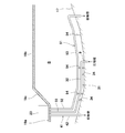
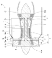
- FIG. 1 is a schematic cross-sectional view of an aircraft gas turbine engine according to the first embodiment.
- FIG. 2 is a front view of the aircraft gas turbine engine shown in FIG. 1 as viewed from the front.
- FIG. 3 is an enlarged view of a part of the bypass path shown in FIG.
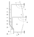
- FIG. 4 is an enlarged view of a part of the bypass path of the aircraft gas turbine engine according to the first modification of the first embodiment.
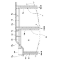
- FIG. 5 is a schematic cross-sectional view of the aircraft gas turbine engine according to the second embodiment.
- FIG. 6 is an enlarged view of a part of the bypass path shown in FIG.
- FIG. 7 is an enlarged view of a part of the bypass path of the aircraft gas turbine engine according to the second modification of the second embodiment.
- forward means the upstream side in the direction in which air flows in the engine
- rear means the downstream side in the direction in which air flows in the engine. That is, “front” means the side where the fan is provided in the axial direction of the engine rotation axis, and “rear” means the side where the fan is provided in the axial direction of the engine rotation axis. Means the side.
- the "radial direction” means a direction orthogonal to the rotation axis of the rotation axis of the engine.
- “Circular direction” means the direction around the rotation axis of the rotation axis of the engine.
- aircraft is a concept including an airplane flying by a propulsive force generated by a gas turbine, an unmanned flying object, and the like.
- FIG. 1 is a cross-sectional view of an aircraft gas turbine engine 1A according to the first embodiment.
- FIG. 2 is a front view of the gas turbine engine 1A shown in FIG. 1 as viewed from the front.
- the gas turbine engine is exemplified for an aircraft, but the gas turbine engine is not particularly limited to the aircraft.
- the aircraft gas turbine engine 1A includes a rotating shaft 2, a fan 3, a compressor 4, a combustor 5, a turbine 6, and a casing 7.
- the rotating shaft 2 extends in the front-rear direction of the gas turbine engine 1A.
- the rotating shaft 2 is supported by a plurality of bearings 8 arranged along the axial direction of the rotating shaft 2.
- the fan 3 is connected to the front portion of the rotating shaft 2 and rotates together with the rotating shaft 2.
- the compressor 4, the combustor 5, and the turbine 6 are arranged in this order from the front to the rear along the rotation shaft 2.
- the casing 7 is a tubular object having an axis that coincides with the rotation axis of the rotation shaft 2, and houses the rotation shaft 2, the fan 3, the compressor 4, the combustor 5, and the turbine 6.
- the gas turbine engine 1A is a twin-screw gas turbine engine.
- the compressor 4 has a low-pressure compressor 13 and a high-pressure compressor 14 arranged behind the low-pressure compressor 13.
- the low-pressure compressor 13 and the high-pressure compressor 14 are both axial-flow compressors.
- the types of the low-pressure compressor 13 and the high-pressure compressor 14 are not limited to this.
- the high pressure compressor 14 may be a centrifugal compressor.
- the turbine 6 has a low pressure turbine 15 and a high pressure turbine 16 arranged in front of the low pressure turbine 15.
- the rotating shaft 2 has a low-pressure shaft 11 that connects the low-pressure compressor 13 to the low-pressure turbine 15 and a high-pressure shaft 12 that connects the high-pressure compressor 14 to the high-pressure turbine 16.
- the high pressure shaft 12 is a tubular shaft having a hollow space inside.
- the low pressure shaft 11 is inserted into the hollow space of the high pressure shaft 12.
- the low pressure turbine 15 is connected to the fan 3 via a low pressure shaft 11.
- Casing 7 has an inner shell 17, an outer shell 18, and a plurality of struts 19.
- the inner shell 17 has a substantially cylindrical shape and houses a compressor 4, a combustor 5, and a turbine 6.
- the outer shell 18 has a substantially cylindrical shape, and is arranged concentrically with the inner shell 17 in a state of being separated radially outward from the inner shell 17.
- the rigidity of the inner shell 17 is higher than that of the outer shell 18.
- the plurality of struts 19 are arranged at intervals in the circumferential direction. Each strut 19 connects the inner shell 17 to the outer shell 18.
- the strut 19 extends radially inward from the outer shell 18, penetrates the inner shell 17 in the radial direction, and extends to a flow path of air compressed by the compressor 4.
- the struts 19 are arranged at corresponding positions between the low-pressure compressor 13 and the high-pressure compressor 14 in the axial direction of the rotating shaft 2, but the position of the struts 19 is not limited to this.
- the casing 7 may have struts other than the struts 19.
- the casing 7 may have struts in front of the low-pressure compressor 13 and behind the high-pressure compressor 14 in the axial direction of the rotating shaft 2.
- a cylindrical bypass path B is formed between the inner shell 17 and the outer shell 18. A part of the air sucked by the fan 3 is sent to the inside of the inner shell 17, that is, the low-pressure compressor 13, and the rest passes through the bypass path B and is discharged to the rear.
- the outer peripheral surfaces of the outer shell 18 of the casing 7 include a first region 18a, a second region 18b provided behind the first region 18a, a first region 18a, and a second region. It has a third region 18c that connects the 18b.
- the first region 18a has a smaller diameter than the second region 18b.
- the first region 18a is provided at a position corresponding to at least the low-pressure compressor 13 in the front-rear direction (rotational axis direction).
- the second region 18b is provided at a position corresponding to at least the combustor 5 in the front-rear direction (rotational axis direction).
- the third region 18c is an inclined region whose diameter gradually increases toward the rear.
- a plurality of electric auxiliary machines 21 are installed in the first region 18a along the outer peripheral surface of the first region 18a.
- the electric auxiliary machine 21 is arranged radially inside the outer peripheral surface of the second region 18b when viewed from the front.
- the electric auxiliary machine 21 includes an electric fuel pump 22, an oil mist generator 23, and a controller 25.
- the electric fuel pump 22 supplies fuel from a fuel tank (not shown) to the combustor 5.
- the oil mist generator 23 generates oil mist by mixing the compressed air extracted from the compressor 4 and the oil.
- the controller 25 controls the electric fuel pump 22 and the oil mist generator 23 in response to predetermined sensor data and external commands.
- the oil mist generator 23 includes a first oil mist generator 23A and a second oil mist generator 23B.
- the first and second oil mist generators 23A and 23B each include a lubricating oil tank (not shown) and an electric lubricating oil pump 24 that mixes the oil in the lubricating oil tank with the compressed air extracted from the compressor 4. Be prepared.
- the electric lubricating oil pumps 24 of the first and second oil mist generators 23A and 23B are arranged in the circumferential direction along the outer peripheral surface of the outer shell 18 of the casing 7.
- the air pipe 31 and the first and second oil mist pipes 41 and 51 are connected to the oil mist generator 23.
- the air pipe 31 guides the compressed air extracted from the compressor 4 to the oil mist generator 23.
- the air pipe 31 is connected to an air extraction port 9 for extracting compressed air compressed by the compressor 4.
- the bleed air port 9 is provided at a position in the inner shell 17 where compressed air is extracted from, for example, the middle stage or the last stage of the high-pressure compressor 14. However, the bleed air port 9 may be provided in the middle of the low-pressure compressor 13 or between the low-pressure compressor 13 and the high-pressure compressor 14.
- Compressed air guided by the air pipe 31 flows into the first and second oil mist pipes 41 and 51.
- the first oil mist generator 23A generates an oil mist by discharging a small amount of oil to the compressed air supplied from the air pipe 31 by the electric lubricating oil pump 24.
- the oil mist generated by the first oil mist generator 23A is guided to the first oil mist pipe 41.
- the second oil mist generator 23B generates oil mist by discharging a small amount of oil to the compressed air supplied from the air pipe 31 by its electric lubricating oil pump 24.
- the oil mist generated by the second oil mist generator 23B is guided to the second oil mist pipe 51.
- the first and second oil mist pipes 41 and 51 guide the oil mist generated by the oil mist generator 23 to a plurality of bearings 8 that support the rotating shaft 2 in the space inside the inner shell 17 in the radial direction.
- the plurality of bearings 8 include a front bearing 8a located in front of the air extraction port 9 and a rear bearing 8b located behind the air extraction port 9.
- the front bearing 8a supports a portion of the low-pressure shaft 11 on the front side of the high-pressure shaft 12.
- the rear bearing 8b supports a portion of the low-pressure shaft 11 behind the high-pressure shaft 12.
- the first oil mist pipe 41 supplies oil mist to the front bearing 8a (more specifically, the bearing chamber accommodating the front bearing 8a) to lubricate the front bearing 8a.
- the second oil mist pipe 51 supplies oil mist to the rear bearing 8b (more specifically, the bearing chamber accommodating the rear bearing 8b) to lubricate the rear bearing 8b.
- the oil mist that cooled the front bearing 8a and the rear bearing 8b is guided to the bypass path B through the discharge flow path (not shown), and is discharged to the bypass path B, respectively.
- the drain channel may be provided in the struts 19 and struts arranged at other positions.
- a part of the air pipe 31 and the first and second oil mist pipes 41 and 51 may be formed by, for example, a casing or a housing.
- FIG. 3 is an enlarged view of a part of the bypass path B shown in FIG. In FIG. 3, the strut 19 is omitted.
- the air extraction port 9 is installed behind the oil mist generator 23.
- the bleeding port 9 is located behind the third region 18c in the axial direction of the rotating shaft 2.
- the air pipe 31 extends in the axial direction of the rotation shaft 2 along the outer surface of the inner shell 17 from the vicinity of the air extraction port 9 in the bypass path B toward the front. Then, the air pipe 31 extends radially outward from the vicinity of the outer surface of the inner shell 17 at a position corresponding to the oil mist generator 23 in the axial direction, penetrates the first region 18a of the outer shell 18, and oils. Connect to the mist generator 23.
- the air pipe 31 has a first heat exchange unit 32 and a second heat exchange unit 33.
- the first and second heat exchange units 32 and 33 are arranged in the bypass path B, and are cooled by coming into contact with the air flowing through the bypass path B.
- the first and second heat exchange units 32 and 33 are exposed in the bypass path B, respectively.
- the first heat exchange unit 32 extends in the axial direction of the rotation shaft 2 along the outer surface of the inner shell 17 along the bypass path B. Specifically, the first heat exchange unit 32 extends from a position corresponding to the bleeding port 9 in the axial direction of the rotating shaft 2 to a position corresponding to the oil mist generating device 23.
- the first heat exchange unit 32 is supported on the outer surface of the inner shell 17 by at least one support member 34 extending in the radial direction.
- the downstream end of the first heat exchange section 32 in the direction in which the compressed air flows is connected to the upstream end of the second heat exchange section 33 in the direction in which the compressed air flows.
- the second heat exchange unit 33 extends in the radial direction of the rotating shaft 2 along the bypass path B toward the oil mist generator 23.
- the compressed air flowing through the first and second heat exchange units 32 and 33 is cooled by the low-temperature air passing through the bypass path B and guided to the oil mist generator 23.
- the front bearing 8a is arranged at a position corresponding to the oil mist generator 23 in the axial direction of the rotating shaft 2 (see also FIG. 1).
- the first oil mist pipe 41 extends radially from the first oil mist generator 23A toward the front bearing 8a so as to penetrate the first region 18a and the inner shell 17 of the outer shell 18.
- the first oil mist pipe 41 has a third heat exchange section 42.
- the third heat exchange unit 42 is arranged in the bypass path B, and is cooled by coming into contact with the air flowing through the bypass path B.
- the third heat exchange unit 42 is exposed in the bypass path B.
- the oil mist flowing through the third heat exchange section 42 is cooled by the low-temperature air passing through the bypass path B and guided to the front bearing 8a.
- the third heat exchange section 42 of the first oil mist pipe 41 may be provided on the outer surface of the strut 19 (not shown) in FIG. 3 so as to be in contact with the air flowing through the bypass path B.
- the rear bearing 8b is arranged behind the bleeding port 9 in the axial direction of the rotating shaft 2.
- the second oil mist pipe 51 extends radially inward from the oil mist generator 23B and penetrates the first region 18a of the outer shell 18. Then, the second oil mist pipe 51 extends in the axial direction of the rotating shaft 2 along the outer surface of the inner shell 17 in the bypass path B, and penetrates the outer shell 18 at a position corresponding to the rear bearing 8b in the axial direction. doing.
- the second oil mist pipe 51 has a fourth heat exchange section 52 and a fifth heat exchange section 53.
- the fourth and fifth heat exchange units 52 and 53 are arranged in the bypass path B, and are cooled by coming into contact with the air flowing through the bypass path B. In the present embodiment, the fourth and fifth heat exchange units 52 and 53 are exposed in the bypass path B, respectively.
- the fourth heat exchange unit 52 is located at a position corresponding to the oil mist generator 23 in the axial direction of the rotating shaft 2.
- the fourth heat exchange unit 52 extends in the radial direction of the rotating shaft 2 in the bypass path B.
- the downstream end of the fourth heat exchange section 52 in the direction in which the oil mist flows is connected to the upstream end of the fifth heat exchange section 53 in the direction in which the oil mist flows.
- the fifth heat exchange unit 53 extends in the axial direction of the rotation shaft 2 along the outer surface of the inner shell 17 along the bypass path B.
- the fifth heat exchange unit 53 extends from a position corresponding to the oil mist generator 23 in the axial direction of the rotating shaft 2 to a position corresponding to the rear bearing 8b.
- the fifth heat exchange unit 53 is supported on the outer surface of the inner shell 17 by at least one support member 54 extending in the radial direction.
- the oil mist flowing through the fourth and fifth heat exchange portions 52 and 53 is cooled by the low-temperature air flowing through the bypass path B and guided to the rear bearing 8b.
- the compressed air flowing through the heat exchange units 32 and 33 is cooled by the low-temperature air passing through the bypass path B, and the inside of the heat exchange units 42, 52 and 53 is cooled.
- the flowing oil mist is cooled by the low temperature air passing through the bypass path B. Therefore, it is not necessary to separately provide a heat exchanger for cooling the oil mist in the gas turbine engine.
- the heat exchanger provided separately can be miniaturized. Therefore, it is possible to supply a lower temperature oil mist to the bearing while reducing the size of the gas turbine engine.
- the heat exchange unit 32 and 53 extend in the axial direction of the rotating shaft 2 in the bypass path B, the heat exchange unit can be lengthened with a simple configuration, and the inside of the heat exchange units 32 and 53 can be lengthened, respectively.
- the compressed air and oil mist that pass through can be made colder.
- first and second oil mist generators 23A and 23B are installed on the outer peripheral surface of the outer shell 18 and in front of the bleed air port 9, and the heat exchange portion 32 of the air pipe 31 is provided. It extends axially along the bypass path B. Therefore, the length of the heat exchange unit 32 can be increased while suppressing the overall length of the air pipe 31 from becoming long.
- the first region 18a on the outer peripheral surface of the outer shell 18 on which the oil mist generating device 23 is installed has a reduced diameter, the amount of protrusion of the oil mist generating device 23 to the outside in the radial direction is reduced, and the gas turbine.
- the front projected area of the engine can be reduced.
- the oil mist generator 23 includes the first oil mist generator 23A and the second oil mist generator 23B, the individual oil mist generators can be miniaturized to the outside of the oil mist generator 23 in the radial direction. The amount of protrusion to the oil can be further reduced.
- both the heat exchange portion 32 of the air pipe and the heat exchange portion 53 of the second oil mist pipe 51 are bypass paths B. Since it extends in the axial direction at, the oil mist leading to the rear bearing 8b can be lowered to a lower temperature, and the cooling performance of the rear bearing 8b can be improved.
- the second heat exchange section 33 and the fourth heat exchange section 52 extending in the axial direction in the bypass path B are supported by the outer peripheral surface of the inner shell 17. Therefore, the air pipe 31 and the second oil mist pipe 51 are more stable than when the second heat exchange unit 33 and the fourth heat exchange unit 52 are supported by the outer shell 18 having a lower rigidity than the inner shell 17. Can be supported.
- FIG. 4 is an enlarged view of a part of the bypass path of the aircraft gas turbine engine according to the first modification of the first embodiment.
- the strut 19 is hollow.
- the strut 19 is formed so that air from the bypass path B does not enter the internal space thereof.
- the axially extending portion of the rotating shaft 2 in the air pipe 31 and the second oil mist pipe 51 penetrates the peripheral wall of the strut 19. Further, in each of the air pipe 31 and the first and second oil mist pipes 41 and 51, the portion extending in the radial direction of the rotating shaft 2 between the inner shell 17 and the outer shell 18 is inside the strut 19. Is inserted.
- the portions of the air pipe 31 and the first and second oil mist pipes 41 and 51 located inside the struts 19 do not come into contact with the air flowing through the bypass path B.
- the air pipe 31 has a first heat exchange unit 32 extending in the axial direction of the rotating shaft 2, but does not have a second heat exchange unit 33 extending in the radial direction of the rotating shaft 2.
- the first oil mist pipe 41 does not have the third heat exchange section 42.
- the second oil mist pipe 51 has a fifth heat exchange section 53 extending in the axial direction of the rotary shaft 2, but does not have a fourth heat exchange section 52 extending in the radial direction of the rotary shaft 2.
- the strut 19 may be solid. Further, when the air pipe 31 and each of the first and second oil mist pipes 41 and 51 form an air flow path in, for example, a solid strut 19, the inner peripheral wall of the strut 19 forming the flow path. It may be composed of.
- the air pipe 31 has the first heat exchange unit 32 and the second oil mist pipe 51 has the fifth heat exchange unit 53, the same effect as that of the first embodiment can be obtained in the first modification. can get.
- FIG. 5 is a cross-sectional view of the aircraft gas turbine engine 1B according to the second embodiment.
- FIG. 6 is an enlarged view of a part of the bypass path B shown in FIG. In FIG. 6, the strut 19 is omitted.
- the air pipe 31 and the second oil mist pipe 51 supported on the outer surface of the inner shell 17 instead of the air pipe 61 and the second oil mist pipe 71 supported on the inner surface of the outer shell 18 It differs from the first embodiment in that it has. In the following description, the air pipe 61 and the second oil mist pipe 71 will be described, and the description of other elements will be omitted.
- the air pipe 61 extends radially outward from the air extraction port 9 at the bypass path B. Then, the vicinity of the inner surface of the outer shell 18 extends forward along the inner surface of the outer shell 18 in the axial direction of the rotation shaft 2, penetrates the third region 18c of the outer shell 18, and is connected to the oil mist generator 23. To do.
- the air pipe 61 has a first heat exchange unit 62 and a second heat exchange unit 63.
- the first and second heat exchange units 62 and 63 are arranged in the bypass path B, and are cooled by coming into contact with the air flowing through the bypass path B.
- the first and second heat exchange units 62 and 63 are exposed in the bypass path B, respectively.
- the first heat exchange unit 62 extends from the bleed air port 9 toward the outer shell 18 in the radial direction of the rotating shaft 2 by a bypass path B.
- the downstream end of the first heat exchange section 62 in the direction in which the compressed air flows is connected to the upstream end of the second heat exchange section 63 in the direction in which the compressed air flows.
- the second heat exchange unit 63 extends in the axial direction of the rotation shaft 2 along the inner surface of the outer shell 18 along the bypass path B. Specifically, the second heat exchange unit 63 extends from a position corresponding to the bleeding port 9 in the axial direction of the rotating shaft 2 to the surface of the outer shell 18 opposite to the third region 18c.
- the second heat exchange unit 63 is supported on the inner surface of the outer shell 18 by at least one support member 64 extending in the radial direction.
- the compressed air flowing through the first and second heat exchange units 62 and 63 is cooled by the low-temperature air passing through the bypass path B and guided to the oil mist generator 23.
- the second oil mist pipe 71 extends rearward from the oil mist generator 23B and penetrates the third region 18c of the outer shell 18 in the axial direction of the rotating shaft 2. Then, the second oil mist pipe 71 extends in the axial direction of the rotating shaft 2 along the inner surface of the outer shell 18 in the bypass path B, and extends in the radial direction at a position corresponding to the rear bearing 8b in the axial direction. It penetrates the inner shell 17.
- the second oil mist pipe 71 has a fourth heat exchange section 72 and a fifth heat exchange section 73.
- the fourth and fifth heat exchange units 72 and 73 are arranged in the bypass path B, and are cooled by coming into contact with the air flowing through the bypass path B.
- the fourth and fifth heat exchange units 72 and 73 are exposed in the bypass path B, respectively.
- the fourth heat exchange unit 72 extends along the inner surface of the outer shell 18 from the surface of the outer shell 18 opposite to the third region 18c to the position corresponding to the rear bearing 8b in the axial direction of the rotating shaft 2.
- the fourth heat exchange portion 72 is supported on the inner surface of the outer shell 18 by at least one support member 74 extending in the radial direction.
- the downstream end of the fourth heat exchange section 72 in the direction in which the oil mist flows is connected to the upstream end of the fifth heat exchange section 73 in the direction in which the oil mist flows.
- the fifth heat exchange unit 73 is located at a position corresponding to the rear bearing 8b in the axial direction of the rotating shaft 2.
- the fifth heat exchange unit 73 extends in the radial direction of the rotating shaft 2 in the bypass path B.
- the oil mist flowing through the fourth and fifth heat exchange portions 72 and 73 is cooled by the low-temperature air passing through the bypass path B and guided to the rear bearing 8b.
- the second heat exchange section 63 and the fourth heat exchange section 72 extending in the axial direction in the bypass path B are supported by the inner peripheral surface of the outer shell 18. Therefore, heat is less likely to be transferred from the inner shell 17 as compared with the case where the second heat exchange unit 63 and the fourth heat exchange unit 72 are supported by the inner shell 17, and the second heat exchange unit 63 and the fourth heat exchange unit 63 and the fourth heat exchange unit 72.
- the cooling performance of the unit 72 can be improved.
- the second heat exchange section 63 and the fourth heat exchange section 72 are located at positions overlapping the third region of the outer shell 18, so that the bypass path B is used. It is difficult for foreign matter that has entered to hit the second heat exchange section 63 and the fourth heat exchange section 72. Further, since the air pipe 61 and the oil mist pipe 71 extend axially in the bypass path B and penetrate the third region 18c, the air pipe 61 and the oil mist pipe 71 are compared with the case where the air pipe 61 and the oil mist pipe 71 penetrate the second region 18b. It is possible to prevent the total length of 71 from becoming long.
- FIG. 7 is an enlarged view of a part of the bypass path of the aircraft gas turbine engine according to the second modification of the second embodiment.
- the casing 7 has struts 19b, 19c other than the struts 19 that connect the inner shell 17 to the outer shell 18.
- the struts 19b are arranged at positions corresponding to the bleeding ports 9 in the axial direction of the rotating shaft 2.
- the struts 19c are arranged at positions corresponding to the rear bearings 8b in the axial direction of the rotating shaft 2.
- the struts 19, 19b, and 19c are hollow, respectively.
- the struts 19, 19b, 19c are formed so that air from the bypass path B does not enter the internal space thereof.
- the portion of the air pipe 61 located inside the strut 19 does not come into contact with the air flowing through the bypass path B.
- the air pipe 61 has a second heat exchange portion 63 extending in the axial direction of the rotating shaft 2, but does not have a first heat exchange portion 62 extending in the radial direction of the rotating shaft 2. ..
- the first oil mist pipe 41 a portion extending in the radial direction of the rotating shaft 2 between the inner shell 17 and the outer shell 18 inserts the inside of the strut 19.
- the first oil mist pipe 41 does not have the third heat exchange section 42, as in the first modification.
- the second oil mist pipe 71 has a fourth heat exchange portion 72 extending in the axial direction of the rotating shaft 2, but a fifth heat exchange portion 73 extending in the radial direction of the rotating shaft 2. I don't have it.
- each of the air pipe 61 and the first and second oil mist pipes 41 and 71 forms the flow path when the air flow path is formed in the solid struts 19, 19b and 19c, respectively. It may be composed of the inner peripheral walls of the struts 19, 19b, 19c.
- the air pipe 61 has the second heat exchange unit 63 and the second oil mist pipe 71 has the fourth heat exchange unit 72, the same effect as that of the second embodiment can be obtained in the second modification. can get.
- the number of air pipes, the number of oil mist pipes, the arrangement of air pipes and oil mist pipes in the gas turbine engines 1A and 1B, and the like are not limited to those described in the above embodiment.
- the gas turbine engine may include a plurality of air pipes, in which case only some of the air pipes have a heat exchange section. You may.
- the gas turbine engine may have a plurality of air extraction ports, and an air pipe may be connected to each of the plurality of air extraction ports.
- the air pipe connected to one air extraction port may have a plurality of branch pipes extending from one pipe in a plurality of branches, and each branch pipe may have a heat exchange section arranged in a bypass path. You may have.
- the gas turbine engine according to at least some embodiments of the present invention may include one or more oil mist pipes. Only a part of the oil mist pipes among the plurality of oil mist pipes may have a heat exchange section. For example, in the first embodiment, only one of the first and second oil mist pipes 41 and 51 may have a heat exchange unit.
- the number of oil mist pipes and the number of bearings 8 may be the same or different.
- the first oil mist pipe 41 may supply the oil mist to a plurality of front bearings (for example, a bearing that supports the low pressure shaft 11 and a bearing that supports the high pressure shaft 12) located in front of the air extraction port 9.
- the second oil mist pipe 51 may supply the oil mist to a plurality of rear bearings (for example, a bearing that supports the low pressure shaft 11 and a bearing that supports the high pressure shaft 12) located behind the air extraction port 9.
- the air pipe may have a configuration having only one of the first heat exchange section and the second heat exchange section.
- one of the axially extending portion and the radially extending portion of the rotating shaft in the air pipe may be completely covered with a protective member so as not to come into contact with the air flowing through the bypass path.
- the second oil mist pipe may have a configuration having only one of the fourth heat exchange section and the fifth heat exchange section.
- the protective member that covers the pipe so as not to come into contact with the air passing through the bypass path may be a strut as shown in the above-mentioned modifications 1 and 2.
- each heat exchange part of the air pipe and the oil mist pipe does not have to be exposed, and is covered with a protective member (not shown) so as to come into contact with the air passing through the bypass path B. May be good.
- the protective member may be provided with a plurality of holes through which air passes.
- the position of the extraction port is not limited to that described in the above embodiment.
- the bleeding port may be provided at a position corresponding to the third region 18c, for example, a position corresponding to the oil mist generating device 23 in the axial direction of the rotating shaft 2.
- the heat exchange portions extending in the axial directions of the air pipe and the oil mist pipe were supported by the support member 34 extending in the radial direction, but the method of supporting the air pipe and the oil mist pipe in each bypass path is this. Not limited.
- the heat exchange portion extending in the axial direction in the bypass path may be in contact with the outer surface of the inner shell or the inner surface of the outer shell.
- the shape of the casing 7 is not limited to that described in the above embodiment.
- the oil mist generator 23 does not have to be located in the first region 18a.
- the oil mist generating device 23 may be located at a position corresponding to the bleeding port 9 or behind the bleeding port 9 in the axial direction of the rotating shaft 2. Further, the number of oil mist generators included in the oil mist generator 23 may be one or three or more.
- the gas turbine engine includes a plurality of oil mist generators, a part of the plurality of oil mist generators may be located in front of the air extraction port, and the rest may be located behind the air extraction port.
- gas turbine engine is not limited to the twin-screw gas turbine engine, and may be a single-screw gas turbine engine.
Landscapes
- Engineering & Computer Science (AREA)
- Chemical & Material Sciences (AREA)
- Combustion & Propulsion (AREA)
- General Engineering & Computer Science (AREA)
- Mechanical Engineering (AREA)
- Physics & Mathematics (AREA)
- Fluid Mechanics (AREA)
- Oil, Petroleum & Natural Gas (AREA)
- Motor Or Generator Cooling System (AREA)
Abstract
Description
そこで、本発明は、ガスタービンエンジンの小型化を図りつつ、より低温のオイルミストを軸受へ供給することができるガスタービンエンジンを提供することを目的とする。
図1は、第1実施形態に係る航空機用ガスタービンエンジン1Aの断面図である。図2は、図1に示すガスタービンエンジン1Aの前方から見た正面図である。なお、本実施形態および後述の第2実施形態では、ガスタービンエンジンとして航空機用が例示されているが、ガスタービンエンジンは特に航空機用に限定されるものではない。図1に示すように、航空機用ガスタービンエンジン1Aは、回転軸2、ファン3、圧縮機4、燃焼器5、タービン6及びケーシング7を備える。回転軸2は、ガスタービンエンジン1Aの前後方向に延びる。回転軸2は、当該回転軸2の軸線方向に沿って配置された複数の軸受8で支持されている。ファン3は、回転軸2の前部に接続され、回転軸2と共に回転する。圧縮機4、燃焼器5及びタービン6は、この順に前方から後方に向けて回転軸2に沿って並んでいる。ケーシング7は、回転軸2の回転軸線と一致する軸線を有する筒状物であり、回転軸2、ファン3、圧縮機4、燃焼器5及びタービン6を収容している。
図4は、第1実施形態の変形例1に係る航空機用ガスタービンエンジンのバイパス路の一部を拡大した図である。変形例1では、ストラット19は、中空となっている。ストラット19は、その内部空間にバイパス路Bからの空気が入り込まないように形成されている。空気配管31及び第2オイルミスト配管51における回転軸2の軸方向に延びる部分は、ストラット19の周壁を貫通している。また、空気配管31並びに第1及び第2オイルミスト配管41,51の各々の配管のうち、内殻17と外殻18との間において回転軸2の径方向に延びる部分が、ストラット19の内部を挿通する。
次に、第2実施形態に係る航空機用ガスタービンエンジン1Bについて、図5及び6を参照して説明する。図5は、第2実施形態に係る航空機用ガスタービンエンジン1Bの断面図である。図6は、図5に示すバイパス路Bの一部を拡大した図である。なお、図6において、ストラット19は省略する。第2実施形態では、内殻17の外表面に支持された空気配管31及び第2オイルミスト配管51の代わりに、外殻18の内表面に支持された空気配管61及び第2オイルミスト配管71を有する点で第1実施形態と異なる。以下の説明では、空気配管61及び第2オイルミスト配管71について説明し、他の要素については説明を省略する。
図7は、第2実施形態の変形例2に係る航空機用ガスタービンエンジンのバイパス路の一部を拡大した図である。変形例2では、ケーシング7が、内殻17を外殻18に連結する、ストラット19以外のストラット19b,19cを有する。ストラット19bは、回転軸2の軸方向における抽気口9に対応する位置に配置されている。また、ストラット19cは、回転軸2の軸方向における後軸受8bに対応する位置に配置されている。ストラット19,19b,19cは、それぞれ中空となっている。ストラット19,19b,19cは、その内部空間にバイパス路Bからの空気が入り込まないように形成されている。
本発明は、上述した実施形態に限定されるものではなく、本発明の要旨を逸脱しない範囲で種々の変形が可能である。
2 :回転軸
3 :ファン
4 :圧縮機
5 :燃焼器
6 :タービン
7 :ケーシング
8 :軸受
8a :前軸受
8b :後軸受
9 :抽気口
17 :内殻
18 :外殻
18a :第1領域
18b :第2領域
18c :第3領域
23 :オイルミスト生成装置
23A :第1オイルミスト生成器
23B :第2オイルミスト生成器
31,61 :空気配管
32,62 :第1熱交換部
33,63 :第2熱交換部
41 :第1オイルミスト配管
42 :第3熱交換部
51,71 :第2オイルミスト配管
52,72 :第4熱交換部
53,73 :第5熱交換部
B :バイパス路
Claims (6)
- 圧縮機、燃焼器及びタービンが回転軸に沿って並んで配置されたガスタービンエンジンであって、
前記圧縮機の前方に配置され、前記回転軸に連動して回転するファンと、
前記圧縮機、前記燃焼器及び前記タービンが収容される内殻と、前記ファンが送出する一部の空気が通流するバイパス路を前記内殻との間に形成する外殻と、を有するケーシングと、
前記内殻の内側に配置された複数の軸受と、
前記外殻の外側に配置され、少なくとも1つの抽気口を通じて前記圧縮機から抽気した圧縮空気とオイルとを混在させてオイルミストを生成するオイルミスト生成装置と、
前記圧縮機から抽気した圧縮空気を前記オイルミスト生成装置に導く少なくとも1つの空気配管と、
前記オイルミスト生成装置にて生成した前記オイルミストを前記複数の軸受に導く少なくとも1つのオイルミスト配管と、を備え、
前記空気配管及び前記オイルミスト配管の少なくとも一方が、前記バイパス路を通流する空気により冷却される、前記バイパス路に配置された熱交換部を有する、ガスタービンエンジン。 - 前記熱交換部の少なくとも一部は、前記バイパス路にて前記回転軸の軸方向に延びている、請求項1に記載のガスタービンエンジン。
- 前記オイルミスト生成装置は、前記外殻の外周面であって且つ前記抽気口より前方又は後方に設置されており、
少なくとも前記空気配管は、前記熱交換部を有しており、
前記空気配管が有する前記熱交換部は、前記軸方向における前記抽気口と前記オイルミスト生成装置との間の少なくとも一部で、前記バイパス路にて前記軸方向に延びている、請求項2に記載のガスタービンエンジン。 - 前記外殻の外周面は、前記抽気口の前方に位置する第1領域と、前記第1領域の後方に位置し、前記第1領域よりも大径である第2領域と、前記第1領域と前記第2領域とをつなぐ第3領域と、を有し、
前記オイルミスト生成装置は、前記第1領域に設置される、請求項3に記載のガスタービンエンジン。 - 前記空気配管及び前記オイルミスト配管の少なくとも一方は、前記バイパス路にて前記軸方向に延びて前記第3領域を貫通する、請求項4に記載のガスタービンエンジン。
- 前記複数の軸受は、前記抽気口より前方に位置する前軸受と、前記抽気口より後方に位置する後軸受とを含み、
前記オイルミスト生成装置は、第1オイルミスト生成器と第2オイルミスト生成器とを含み、
前記少なくとも1つのオイルミスト配管は、前記第1オイルミスト生成器にて生成した前記オイルミストを前記前軸受に導く第1オイルミスト配管と、前記第2オイルミスト生成器にて生成した前記オイルミストを前記後軸受に導く第2オイルミスト配管とを含み、
前記第2オイルミスト配管は、前記バイパス流路にて、少なくとも一部が前記回転軸の軸方向に延びる前記熱交換部を含む、請求項1~5のいずれか1項に記載のガスタービンエンジン。
Priority Applications (3)
| Application Number | Priority Date | Filing Date | Title |
|---|---|---|---|
| EP20858778.2A EP4023870B1 (en) | 2019-08-30 | 2020-08-27 | Gas turbine engine |
| US17/638,556 US11746699B2 (en) | 2019-08-30 | 2020-08-27 | Gas turbine engine |
| JP2021543016A JP7365418B2 (ja) | 2019-08-30 | 2020-08-27 | ガスタービンエンジン |
Applications Claiming Priority (2)
| Application Number | Priority Date | Filing Date | Title |
|---|---|---|---|
| JP2019-157864 | 2019-08-30 | ||
| JP2019157864 | 2019-08-30 |
Publications (1)
| Publication Number | Publication Date |
|---|---|
| WO2021039927A1 true WO2021039927A1 (ja) | 2021-03-04 |
Family
ID=74684244
Family Applications (1)
| Application Number | Title | Priority Date | Filing Date |
|---|---|---|---|
| PCT/JP2020/032457 Ceased WO2021039927A1 (ja) | 2019-08-30 | 2020-08-27 | ガスタービンエンジン |
Country Status (4)
| Country | Link |
|---|---|
| US (1) | US11746699B2 (ja) |
| EP (1) | EP4023870B1 (ja) |
| JP (1) | JP7365418B2 (ja) |
| WO (1) | WO2021039927A1 (ja) |
Cited By (1)
| Publication number | Priority date | Publication date | Assignee | Title |
|---|---|---|---|---|
| JP7875339B1 (ja) * | 2025-04-30 | 2026-06-17 | 川崎重工業株式会社 | ガスタービンエンジン |
Families Citing this family (1)
| Publication number | Priority date | Publication date | Assignee | Title |
|---|---|---|---|---|
| JP7152911B2 (ja) * | 2018-09-05 | 2022-10-13 | 川崎重工業株式会社 | 航空機用ガスタービンのオイル供給装置 |
Citations (8)
| Publication number | Priority date | Publication date | Assignee | Title |
|---|---|---|---|---|
| JPS531710A (en) * | 1976-06-14 | 1978-01-10 | Gen Electric | Method and equipment for reducing gas turbine engine exhaust substance |
| JPH1089087A (ja) * | 1996-09-10 | 1998-04-07 | Mitsubishi Heavy Ind Ltd | ガスタービンのオイルミスト発生装置 |
| JP2001165390A (ja) | 1999-12-08 | 2001-06-22 | Kawasaki Heavy Ind Ltd | ベアリング潤滑方法およびベアリング機構 |
| US7748209B1 (en) * | 2006-12-08 | 2010-07-06 | Florida Turbine Technologies, Inc. | Small single use gas turbine engine with oil-less bearing arrangement |
| JP2013083159A (ja) * | 2011-10-06 | 2013-05-09 | Mitsubishi Heavy Ind Ltd | 潤滑油供給装置 |
| JP2014163407A (ja) * | 2013-02-21 | 2014-09-08 | Mitsubishi Heavy Ind Ltd | オイルミスト生成装置 |
| JP2014163236A (ja) * | 2013-02-21 | 2014-09-08 | Mitsubishi Heavy Ind Ltd | オイルミスト生成装置 |
| JP2017187021A (ja) * | 2016-03-11 | 2017-10-12 | ゼネラル・エレクトリック・カンパニイ | アクティブクリアランス制御のための方法および装置 |
Family Cites Families (12)
| Publication number | Priority date | Publication date | Assignee | Title |
|---|---|---|---|---|
| GB889305A (en) * | 1959-11-26 | 1962-02-14 | Rolls Royce | Gas turbine engine |
| GB1013139A (en) * | 1964-09-04 | 1965-12-15 | Rolls Royce | Gas turbine engine |
| US4561246A (en) * | 1983-12-23 | 1985-12-31 | United Technologies Corporation | Bearing compartment for a gas turbine engine |
| US6035627A (en) * | 1998-04-21 | 2000-03-14 | Pratt & Whitney Canada Inc. | Turbine engine with cooled P3 air to impeller rear cavity |
| US7451753B2 (en) * | 2006-04-21 | 2008-11-18 | Pratt & Whitney Canada Corp. | Pre-heating of a liquid in an aircraft reservoir |
| US7862293B2 (en) * | 2007-05-03 | 2011-01-04 | Pratt & Whitney Canada Corp. | Low profile bleed air cooler |
| JP5667651B2 (ja) * | 2013-02-28 | 2015-02-12 | 川崎重工業株式会社 | ミストセパレータ |
| US11162419B2 (en) * | 2018-02-12 | 2021-11-02 | General Electric Company | Method and structure for operating engine with bowed rotor condition |
| US11181007B1 (en) * | 2019-02-28 | 2021-11-23 | Florida Turbine Technologies, Inc. | Gas turbine engine bearing with fuel lubrication and cooling |
| EP4023872B1 (en) * | 2019-08-30 | 2025-09-24 | Kawasaki Jukogyo Kabushiki Kaisha | Gas turbine engine |
| JP7336919B2 (ja) * | 2019-08-30 | 2023-09-01 | 川崎重工業株式会社 | ガスタービンエンジン |
| JP7445452B2 (ja) * | 2020-02-14 | 2024-03-07 | 川崎重工業株式会社 | ガスタービンエンジン |
-
2020
- 2020-08-27 EP EP20858778.2A patent/EP4023870B1/en active Active
- 2020-08-27 JP JP2021543016A patent/JP7365418B2/ja active Active
- 2020-08-27 WO PCT/JP2020/032457 patent/WO2021039927A1/ja not_active Ceased
- 2020-08-27 US US17/638,556 patent/US11746699B2/en active Active
Patent Citations (8)
| Publication number | Priority date | Publication date | Assignee | Title |
|---|---|---|---|---|
| JPS531710A (en) * | 1976-06-14 | 1978-01-10 | Gen Electric | Method and equipment for reducing gas turbine engine exhaust substance |
| JPH1089087A (ja) * | 1996-09-10 | 1998-04-07 | Mitsubishi Heavy Ind Ltd | ガスタービンのオイルミスト発生装置 |
| JP2001165390A (ja) | 1999-12-08 | 2001-06-22 | Kawasaki Heavy Ind Ltd | ベアリング潤滑方法およびベアリング機構 |
| US7748209B1 (en) * | 2006-12-08 | 2010-07-06 | Florida Turbine Technologies, Inc. | Small single use gas turbine engine with oil-less bearing arrangement |
| JP2013083159A (ja) * | 2011-10-06 | 2013-05-09 | Mitsubishi Heavy Ind Ltd | 潤滑油供給装置 |
| JP2014163407A (ja) * | 2013-02-21 | 2014-09-08 | Mitsubishi Heavy Ind Ltd | オイルミスト生成装置 |
| JP2014163236A (ja) * | 2013-02-21 | 2014-09-08 | Mitsubishi Heavy Ind Ltd | オイルミスト生成装置 |
| JP2017187021A (ja) * | 2016-03-11 | 2017-10-12 | ゼネラル・エレクトリック・カンパニイ | アクティブクリアランス制御のための方法および装置 |
Non-Patent Citations (1)
| Title |
|---|
| See also references of EP4023870A4 |
Cited By (1)
| Publication number | Priority date | Publication date | Assignee | Title |
|---|---|---|---|---|
| JP7875339B1 (ja) * | 2025-04-30 | 2026-06-17 | 川崎重工業株式会社 | ガスタービンエンジン |
Also Published As
| Publication number | Publication date |
|---|---|
| JPWO2021039927A1 (ja) | 2021-03-04 |
| EP4023870A1 (en) | 2022-07-06 |
| EP4023870A4 (en) | 2023-09-27 |
| JP7365418B2 (ja) | 2023-10-19 |
| US11746699B2 (en) | 2023-09-05 |
| US20220316396A1 (en) | 2022-10-06 |
| EP4023870B1 (en) | 2026-01-21 |
Similar Documents
| Publication | Publication Date | Title |
|---|---|---|
| CN103883401B (zh) | 组合油底壳装置 | |
| JP6105368B2 (ja) | 油スクープマニホールド | |
| US20180313266A1 (en) | Gas turbine engine oil tank | |
| JP7174169B2 (ja) | ガスタービンエンジン | |
| US10578020B2 (en) | Integral oil tank heat exchanger | |
| JP6193559B2 (ja) | ガスタービンのロードカップリングのための冷却システム | |
| EP3054112B1 (en) | Nose cone assembly and method of circulating air in a gas turbine engine | |
| JP2017082789A (ja) | ガスタービンエンジンサンプ熱交換器 | |
| US10060350B2 (en) | Nose cone assembly and method of circulating air in a gas turbine engine | |
| JP2011231767A (ja) | ガスタービンエンジン | |
| CN106837552A (zh) | 用于冷却飞行器发动机流体的方法及系统 | |
| JP2006063980A (ja) | ガスタービンエンジンのフレーム | |
| BR102016029924A2 (pt) | Heat exchanger assembly, system, method for cooling a fluid and gas turbine engine | |
| JP2005083199A (ja) | ガスタービン設備及び冷却空気供給方法 | |
| JP2017048781A (ja) | ガスタービンエンジンのベアリングコンパートメントにおけるハイドロダイナミックシール | |
| US9797407B2 (en) | Aircraft engine | |
| CN110268152A (zh) | 包括用于通过径向臂向涡轮风扇发动机的排气容置部供应空气的中间流的涡轮风扇发动机 | |
| JP7365418B2 (ja) | ガスタービンエンジン | |
| JP2018519455A (ja) | ガスタービン機関 | |
| JP6375149B2 (ja) | 軸受の排油構造 | |
| JP5818622B2 (ja) | 潤滑油供給装置 | |
| US20150345389A1 (en) | Multi Stage Air Flow Management | |
| US11108302B2 (en) | Electric generator having a liquid coolant system | |
| CN107532800A (zh) | 涡轮机的肘形燃烧室 | |
| JP4735082B2 (ja) | ガスタービンエンジン |
Legal Events
| Date | Code | Title | Description |
|---|---|---|---|
| 121 | Ep: the epo has been informed by wipo that ep was designated in this application |
Ref document number: 20858778 Country of ref document: EP Kind code of ref document: A1 |
|
| ENP | Entry into the national phase |
Ref document number: 2021543016 Country of ref document: JP Kind code of ref document: A |
|
| NENP | Non-entry into the national phase |
Ref country code: DE |
|
| ENP | Entry into the national phase |
Ref document number: 2020858778 Country of ref document: EP Effective date: 20220330 |
|
| WWG | Wipo information: grant in national office |
Ref document number: 2020858778 Country of ref document: EP |