WO2021059985A1 - Dispositif de réfrigération à semi-conducteur - Google Patents
Dispositif de réfrigération à semi-conducteur Download PDFInfo
- Publication number
- WO2021059985A1 WO2021059985A1 PCT/JP2020/034168 JP2020034168W WO2021059985A1 WO 2021059985 A1 WO2021059985 A1 WO 2021059985A1 JP 2020034168 W JP2020034168 W JP 2020034168W WO 2021059985 A1 WO2021059985 A1 WO 2021059985A1
- Authority
- WO
- WIPO (PCT)
- Prior art keywords
- heat
- heat exchanger
- heat medium
- magnetic
- unit
- Prior art date
- Legal status (The legal status is an assumption and is not a legal conclusion. Google has not performed a legal analysis and makes no representation as to the accuracy of the status listed.)
- Ceased
Links
Images


Classifications
-
- F—MECHANICAL ENGINEERING; LIGHTING; HEATING; WEAPONS; BLASTING
- F25—REFRIGERATION OR COOLING; COMBINED HEATING AND REFRIGERATION SYSTEMS; HEAT PUMP SYSTEMS; MANUFACTURE OR STORAGE OF ICE; LIQUEFACTION SOLIDIFICATION OF GASES
- F25B—REFRIGERATION MACHINES, PLANTS OR SYSTEMS; COMBINED HEATING AND REFRIGERATION SYSTEMS; HEAT PUMP SYSTEMS
- F25B21/00—Machines, plants or systems, using electric or magnetic effects
-
- F—MECHANICAL ENGINEERING; LIGHTING; HEATING; WEAPONS; BLASTING
- F25—REFRIGERATION OR COOLING; COMBINED HEATING AND REFRIGERATION SYSTEMS; HEAT PUMP SYSTEMS; MANUFACTURE OR STORAGE OF ICE; LIQUEFACTION SOLIDIFICATION OF GASES
- F25B—REFRIGERATION MACHINES, PLANTS OR SYSTEMS; COMBINED HEATING AND REFRIGERATION SYSTEMS; HEAT PUMP SYSTEMS
- F25B13/00—Compression machines, plants or systems, with reversible cycle
-
- F—MECHANICAL ENGINEERING; LIGHTING; HEATING; WEAPONS; BLASTING
- F25—REFRIGERATION OR COOLING; COMBINED HEATING AND REFRIGERATION SYSTEMS; HEAT PUMP SYSTEMS; MANUFACTURE OR STORAGE OF ICE; LIQUEFACTION SOLIDIFICATION OF GASES
- F25B—REFRIGERATION MACHINES, PLANTS OR SYSTEMS; COMBINED HEATING AND REFRIGERATION SYSTEMS; HEAT PUMP SYSTEMS
- F25B41/00—Fluid-circulation arrangements
- F25B41/20—Disposition of valves, e.g. of on-off valves or flow control valves
-
- F—MECHANICAL ENGINEERING; LIGHTING; HEATING; WEAPONS; BLASTING
- F25—REFRIGERATION OR COOLING; COMBINED HEATING AND REFRIGERATION SYSTEMS; HEAT PUMP SYSTEMS; MANUFACTURE OR STORAGE OF ICE; LIQUEFACTION SOLIDIFICATION OF GASES
- F25B—REFRIGERATION MACHINES, PLANTS OR SYSTEMS; COMBINED HEATING AND REFRIGERATION SYSTEMS; HEAT PUMP SYSTEMS
- F25B41/00—Fluid-circulation arrangements
- F25B41/40—Fluid line arrangements
-
- F—MECHANICAL ENGINEERING; LIGHTING; HEATING; WEAPONS; BLASTING
- F25—REFRIGERATION OR COOLING; COMBINED HEATING AND REFRIGERATION SYSTEMS; HEAT PUMP SYSTEMS; MANUFACTURE OR STORAGE OF ICE; LIQUEFACTION SOLIDIFICATION OF GASES
- F25B—REFRIGERATION MACHINES, PLANTS OR SYSTEMS; COMBINED HEATING AND REFRIGERATION SYSTEMS; HEAT PUMP SYSTEMS
- F25B47/00—Arrangements for preventing or removing deposits or corrosion, not provided for in another subclass
- F25B47/02—Defrosting cycles
- F25B47/022—Defrosting cycles hot gas defrosting
- F25B47/025—Defrosting cycles hot gas defrosting by reversing the cycle
-
- F—MECHANICAL ENGINEERING; LIGHTING; HEATING; WEAPONS; BLASTING
- F25—REFRIGERATION OR COOLING; COMBINED HEATING AND REFRIGERATION SYSTEMS; HEAT PUMP SYSTEMS; MANUFACTURE OR STORAGE OF ICE; LIQUEFACTION SOLIDIFICATION OF GASES
- F25B—REFRIGERATION MACHINES, PLANTS OR SYSTEMS; COMBINED HEATING AND REFRIGERATION SYSTEMS; HEAT PUMP SYSTEMS
- F25B49/00—Arrangement or mounting of control or safety devices
-
- F—MECHANICAL ENGINEERING; LIGHTING; HEATING; WEAPONS; BLASTING
- F25—REFRIGERATION OR COOLING; COMBINED HEATING AND REFRIGERATION SYSTEMS; HEAT PUMP SYSTEMS; MANUFACTURE OR STORAGE OF ICE; LIQUEFACTION SOLIDIFICATION OF GASES
- F25B—REFRIGERATION MACHINES, PLANTS OR SYSTEMS; COMBINED HEATING AND REFRIGERATION SYSTEMS; HEAT PUMP SYSTEMS
- F25B2321/00—Details of machines, plants or systems, using electric or magnetic effects
- F25B2321/002—Details of machines, plants or systems, using electric or magnetic effects by using magneto-caloric effects
- F25B2321/0021—Details of machines, plants or systems, using electric or magnetic effects by using magneto-caloric effects with a static fixed magnet
-
- F—MECHANICAL ENGINEERING; LIGHTING; HEATING; WEAPONS; BLASTING
- F25—REFRIGERATION OR COOLING; COMBINED HEATING AND REFRIGERATION SYSTEMS; HEAT PUMP SYSTEMS; MANUFACTURE OR STORAGE OF ICE; LIQUEFACTION SOLIDIFICATION OF GASES
- F25B—REFRIGERATION MACHINES, PLANTS OR SYSTEMS; COMBINED HEATING AND REFRIGERATION SYSTEMS; HEAT PUMP SYSTEMS
- F25B2321/00—Details of machines, plants or systems, using electric or magnetic effects
- F25B2321/002—Details of machines, plants or systems, using electric or magnetic effects by using magneto-caloric effects
- F25B2321/0023—Details of machines, plants or systems, using electric or magnetic effects by using magneto-caloric effects with modulation, influencing or enhancing an existing magnetic field
-
- F—MECHANICAL ENGINEERING; LIGHTING; HEATING; WEAPONS; BLASTING
- F25—REFRIGERATION OR COOLING; COMBINED HEATING AND REFRIGERATION SYSTEMS; HEAT PUMP SYSTEMS; MANUFACTURE OR STORAGE OF ICE; LIQUEFACTION SOLIDIFICATION OF GASES
- F25B—REFRIGERATION MACHINES, PLANTS OR SYSTEMS; COMBINED HEATING AND REFRIGERATION SYSTEMS; HEAT PUMP SYSTEMS
- F25B2400/00—General features or devices for refrigeration machines, plants or systems, combined heating and refrigeration systems or heat-pump systems, i.e. not limited to a particular subgroup of F25B
- F25B2400/24—Storage receiver heat
-
- Y—GENERAL TAGGING OF NEW TECHNOLOGICAL DEVELOPMENTS; GENERAL TAGGING OF CROSS-SECTIONAL TECHNOLOGIES SPANNING OVER SEVERAL SECTIONS OF THE IPC; TECHNICAL SUBJECTS COVERED BY FORMER USPC CROSS-REFERENCE ART COLLECTIONS [XRACs] AND DIGESTS
- Y02—TECHNOLOGIES OR APPLICATIONS FOR MITIGATION OR ADAPTATION AGAINST CLIMATE CHANGE
- Y02B—CLIMATE CHANGE MITIGATION TECHNOLOGIES RELATED TO BUILDINGS, e.g. HOUSING, HOUSE APPLIANCES OR RELATED END-USER APPLICATIONS
- Y02B30/00—Energy efficient heating, ventilation or air conditioning [HVAC]
-
- Y—GENERAL TAGGING OF NEW TECHNOLOGICAL DEVELOPMENTS; GENERAL TAGGING OF CROSS-SECTIONAL TECHNOLOGIES SPANNING OVER SEVERAL SECTIONS OF THE IPC; TECHNICAL SUBJECTS COVERED BY FORMER USPC CROSS-REFERENCE ART COLLECTIONS [XRACs] AND DIGESTS
- Y02—TECHNOLOGIES OR APPLICATIONS FOR MITIGATION OR ADAPTATION AGAINST CLIMATE CHANGE
- Y02E—REDUCTION OF GREENHOUSE GAS [GHG] EMISSIONS, RELATED TO ENERGY GENERATION, TRANSMISSION OR DISTRIBUTION
- Y02E60/00—Enabling technologies; Technologies with a potential or indirect contribution to GHG emissions mitigation
- Y02E60/14—Thermal energy storage
Definitions
- This disclosure relates to a solid refrigeration system.
- the magnetic refrigeration apparatus disclosed in Patent Document 1 has a plurality of beds, a high temperature side heat exchanger, and a low temperature side heat exchanger.
- the bed, the high temperature side heat exchanger, and the low temperature side heat exchanger are connected to the heat medium circuit.
- the magnetic work material generates heat or absorbs heat as the magnetic field of the magnetic work material fluctuates.
- the heat medium of the heat medium circuit is heated by a magnetic working substance that generates heat.
- the heat medium of the heat medium circuit is cooled by an endothermic magnetic working substance. Due to such an operation, a temperature difference is generated between the heat medium of the high temperature side heat exchanger and the heat medium of the low temperature side heat exchanger.
- the low temperature side heat exchanger In the low temperature side heat exchanger, the temperature of the heat medium becomes low, so frost may form on the surface of the low temperature side heat exchanger.
- the low temperature side heat exchanger is defrosted by transporting the heat medium stored in the high temperature side heat exchanger to the low temperature side heat exchanger.
- the heat medium stored in the high temperature side heat exchanger is used for defrosting the low temperature side heat exchanger.
- the low temperature side heat exchanger cannot be sufficiently defrosted only by the heat of the heat medium in the high temperature side heat exchanger.
- the present disclosure is to provide a solid refrigerating apparatus capable of securing the heat required for defrosting the low temperature side heat exchanger, particularly a magnetic refrigerating apparatus.
- the first aspect of the present disclosure is to induce a calorific effect on the solid refrigerant substance (22), the internal flow paths (24, 25) in which the solid refrigerant substance (22) is arranged, and the solid refrigerant substance (22).
- a solid cooling unit (20) having an inducing unit (23) to induce, at least one first heat exchanger (11), at least one second heat exchanger (12), and the first heat exchanger ( 11), the heat medium circuit (C) to which the second heat exchanger (12) and the internal flow paths (24, 25) are connected, and the heat medium of the heat medium circuit (C) are reciprocally transferred.
- the heat medium heated by the solid cooling unit (20) is dissipated by the first heat exchanger (11) and cooled by the solid cooling unit (20).
- a solid refrigerating apparatus that performs a heating operation in which the heat medium is absorbed by the second heat exchanger (12) and a defrosting operation in which the frost of the second heat exchanger (12) is melted.
- the heat storage unit (13,16) is further provided, and in the defrosting operation, the heat stored in the heat storage unit (13,16) is used to melt the frost of the second heat exchanger (12). ..
- heat is stored in the heat storage section (13, 16) in the heating operation.
- the second heat exchanger (12) is defrosted by the heat stored in the heat storage units (13, 16).
- the heat storage unit includes a tank (13) for storing the heat medium heated by the solid cooling unit (20) in the heating operation, and the defrosting operation is performed. It is provided with a transport unit (14) that transports the heat medium in the tank (13) to the second heat exchanger (12).
- heat is stored in the tank (13) during the heating operation.
- the second heat exchanger (12) is defrosted by the heat stored in the tank (13).
- the third aspect is the first or second aspect, in which the heat storage unit includes a heat storage material (16).
- the heat storage unit includes a heat storage material (16) that stores heat of the heat medium heated by the solid cooling unit (20) in the heating operation, and the defrosting. It is provided with a transport unit (14) that transports the heat of the heat storage material (16) to the second heat exchanger (12) by a heat medium during operation.
- heat is stored in at least the heat storage material (16) in the heating operation.
- the second heat exchanger (12) is defrosted by the heat stored in the heat storage material (16).
- the heat medium heated by the solid cooling unit (20) in the heating operation is the first heat exchanger (11) and the heat storage unit (the heat storage unit (11).
- the heat generated from the solid cooling unit (20) is stored in the heat storage unit (13, 16).
- the second heat exchanger (12) is defrosted by the heat stored in the heat storage units (13, 16).
- the at least one second heat exchanger (12) is composed of a plurality of second heat exchangers (12), and the defrosting operation is a defrosting target.
- a plurality of defrosting operations for changing the second heat exchanger (12) and the second heat exchanger (12) for absorbing heat of the heat medium are included, and in each of the defrosting operations, the solid cooling unit (20) is used.
- the operation of supplying the heat medium of the heat storage unit (13, 16) to the other second heat exchanger (12) to be frosted is executed at the same time.
- the defrosting operation of the sixth aspect a plurality of defrosting operations are performed so that the second heat exchanger (12) to be defrosted is changed.
- the heat medium dissipates heat in the first heat exchanger (11) while the second heat exchanger (12) is defrosted. Therefore, the heating operation can be substantially continued.
- the heat storage unit (13, 16) is downstream of the first heat exchanger (11) in the heat medium circuit (C) during the heating operation. Placed on the side.
- the seventh aspect it is possible to suppress a decrease in the heating capacity of the first heat exchanger (11) due to heat storage in the heat storage units (13, 16) in the heating operation.
- the heat storage unit (13, 16) is parallel to the first heat exchanger (11) in the heat medium circuit (C) during the heating operation. Is placed in.
- the heat medium heated by the solid cooling unit (20) in the heating operation is the first heat exchanger (11) and the heat storage unit. (13,16) flows in parallel so that the heat medium in the heat storage unit (13,16) flows through the first heat exchanger (11) and the second heat exchanger (12) in the defrosting operation. The flow path of the heat medium circuit (C) is switched.
- the heat medium heated by the solid cooling unit (20) can be flowed in parallel to the first heat exchanger (11) and the heat storage unit (13, 16).
- the heat medium of the heat storage unit (13, 16) dissipates heat in the first heat exchanger (11) and the second heat exchanger (12).
- a tenth aspect is that in any one of the fifth to ninth aspects, the heat medium circuit (C) has a heat medium heated by the solid cooling unit (20) at least at the start of the heating operation. It includes a bypass flow path (66,71) that bypasses the heat storage section (13,16).
- the solid refrigerant substance is a magnetic working substance (22), and the inducing portion causes a magnetic field fluctuation in the magnetic working substance (22). It is a magnetic field modulation unit (23) to be applied, and the solid cooling unit is a single-layer magnetic refrigerating unit (20) made of one kind of magnetic working material (22), and is cooled by the magnetic refrigerating unit (20). It is configured to further perform a cooling operation in which the heat medium is absorbed by the first heat exchanger (11) and the heat medium heated by the magnetic refrigeration unit (20) is dissipated by the second heat exchanger (12).
- the heat medium circuit (C) communicates with the internal flow paths (24, 25) of the magnetic refrigeration section (20), respectively, in the first outflow section (41), the first inflow section (42), and the first.
- the switching mechanism (15) includes the two outflow portions (43) and the second inflow portion (44), and the heat medium heated by the magnetic refrigeration portion (20) in the heating operation is the first outflow portion ( 41), the heat medium that flows through the first heat exchanger (11), the heat storage section (13,16), and the first inflow section (42) and is cooled by the magnetic refrigeration section (20) is the first. 2
- a flow path is formed through the outflow section (43), the second heat exchanger (12), and the second inflow section (44), and the heat cooled by the magnetic refrigeration section (20) in the cooling operation.
- the medium flows through the first outflow section (41), the first heat exchanger (11), and the first inflow section (42), and the heat medium heated by the magnetic refrigeration section (20) is the second.
- a flow path is formed through the outflow section (43), the second heat exchanger (12), and the second inflow section (44), and in the defrosting operation, the heat medium of the heat storage section (13, 16) is formed.
- the cooling operation, the heating operation, and the defrosting operation can be switched in the single-layer magnetic refrigerating unit (20).
- the heat stored in the heat storage units (13, 16) in the heating operation is used for defrosting the second heat exchanger (12).
- the solid refrigerant substance is a magnetic working substance (22), and the inducing portion causes a magnetic field fluctuation in the magnetic working substance (22). It is a magnetic field modulation unit (23) to be applied, and the solid cooling unit is a cascade type magnetic refrigeration unit (20) composed of a plurality of types of magnetic working substances (22), and is cooled by the magnetic refrigeration unit (20). It is configured to further perform a cooling operation in which the heat medium is absorbed by the first heat exchanger (11) and the heat medium heated by the magnetic refrigeration unit (20) is dissipated by the second heat exchanger (12).
- the heat medium circuit (C) communicates with the internal flow paths (24, 25) of the magnetic refrigeration section (20), respectively, a low temperature outflow section (51), a low temperature inflow section (52), and a high temperature outflow section.
- the switching mechanism (15) includes the (53) and the high-temperature inflow section (54), and the heat medium heated by the magnetic refrigeration section (20) in the heating operation is the high-temperature outflow section (53) and the first. 1
- the heat medium that flows through the heat exchanger (11), the heat storage section (13,16), and the high temperature inflow section (54) and is cooled by the magnetic refrigeration section (20) is the low temperature outflow section (51).
- a flow path through the second heat exchanger (12) and the low temperature inflow section (52) is formed, and in the cooling operation, the heat medium cooled by the magnetic refrigeration section (20) is the low temperature outflow section (51). ), The first heat exchanger (11), and the low temperature inflow section (52), and the heat medium heated by the magnetic refrigeration section (20) is the high temperature outflow section (53) and the second heat exchange.
- a flow path is formed through the vessel (12) and the high temperature inflow portion (54), and in the defrosting operation, the heat medium of the heat storage portion (13, 16) flows through the second heat exchanger (12). Form a flow path.
- the cooling operation, the heating operation, and the defrosting operation can be switched in the cascade type magnetic refrigerating unit (20).
- the heat stored in the heat storage units (13, 16) in the heating operation is used for defrosting the second heat exchanger (12).
- the solid refrigerant substance is a magnetic working substance (22), and the inducing portion causes a magnetic field fluctuation in the magnetic working substance (22). It is a magnetic field modulation unit (23) to be applied, and the solid cooling unit is a magnetic refrigeration unit (20).
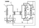
- FIG. 1 is a piping system diagram of the magnetic refrigeration apparatus according to the first embodiment.
- FIG. 2 is a schematic configuration diagram of the magnetic refrigeration unit according to the first embodiment.
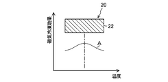
- FIG. 3 is a diagram schematically showing the relationship between the temperature of the single-layer magnetic refrigerating section according to the first embodiment and the magnetic refrigerating effect.
- FIG. 4 is a schematic configuration diagram of the magnetic refrigeration unit according to the first embodiment.
- FIG. 4 (A) shows the first operation
- FIG. 4 (B) shows the second operation.
- FIG. 5 is a schematic configuration diagram of the magnetic refrigeration unit according to the first embodiment.
- FIG. 5 (A) shows the third operation
- FIG. 5 (B) shows the fourth operation.
- FIG. 6 is a block diagram showing a relationship between a control device and a plurality of devices for which signals are exchanged between the control device.
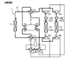
- FIG. 7 is a piping system diagram for explaining the cooling operation in the magnetic refrigeration apparatus according to the first embodiment.
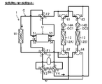
- FIG. 8 is a piping system diagram for explaining the heating operation in the magnetic refrigeration apparatus according to the first embodiment.
- FIG. 9 is a piping system diagram for explaining the defrosting operation in the magnetic refrigeration apparatus according to the first embodiment.
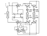
- FIG. 10 is a piping system diagram of the magnetic refrigeration apparatus according to the first modification of the first embodiment.
- FIG. 11 is a schematic configuration diagram of the magnetic refrigeration unit according to the first modification of the first embodiment.
- FIG. 12 is a diagram schematically showing the relationship between the temperature of the cascade-type magnetic refrigeration section and the magnetic refrigeration effect according to the first modification of the first embodiment.
- FIG. 13 is a schematic configuration diagram of the magnetic refrigeration unit according to the first modification of the first embodiment.
- FIG. 13 (A) shows the fifth operation
- FIG. 13 (B) shows the sixth operation.
- FIG. 14 is a piping system diagram for explaining the cooling operation in the magnetic refrigeration apparatus according to the first modification of the first embodiment.
- FIG. 15 is a piping system diagram for explaining a heating operation in the magnetic refrigeration apparatus according to the first modification of the first embodiment.
- FIG. 16 is a piping system diagram for explaining a defrosting operation in the magnetic refrigeration apparatus according to the first modification of the first embodiment.
- FIG. 17 is a piping system diagram for explaining a heating operation in the magnetic refrigeration apparatus according to the second modification of the first embodiment.
- FIG. 18 is a piping system diagram for explaining a defrosting operation in the magnetic refrigeration apparatus according to the second modification of the first embodiment.
- FIG. 19 is a piping system diagram for explaining a heating operation in the magnetic refrigeration apparatus according to the third modification of the first embodiment.
- FIG. 20 is a piping system diagram for explaining a defrosting operation in the magnetic refrigeration apparatus according to the third modification of the first embodiment.
- FIG. 21 is a piping system diagram of the magnetic refrigeration apparatus according to the second embodiment.
- FIG. 22 is a piping system diagram for explaining the cooling operation in the magnetic refrigeration apparatus according to the second embodiment.
- FIG. 23 is a piping system diagram for explaining a heating operation (first heating operation) in the magnetic refrigeration apparatus according to the second embodiment.
- FIG. 24 is a piping system diagram for explaining a heating operation (second heating operation) in the magnetic refrigeration apparatus according to the second embodiment.
- FIG. 25 is a piping system diagram for explaining a defrosting operation (first defrosting operation) in the magnetic refrigerating apparatus according to the second embodiment.
- FIG. 26 is a piping system diagram for explaining a defrosting operation (second defrosting operation) in the magnetic refrigerating apparatus according to the second embodiment.
- FIG. 27 is a piping system diagram of the magnetic refrigeration apparatus according to the first modification of the second embodiment.
- FIG. 28 is a piping system diagram for explaining the cooling operation in the magnetic refrigeration apparatus according to the first modification of the second embodiment.
- FIG. 29 is a piping system diagram for explaining a heating operation (first heating operation) in the magnetic refrigeration apparatus according to the first modification of the second embodiment.
- FIG. 30 is a piping system diagram for explaining a heating operation (second heating operation) in the magnetic refrigeration apparatus according to the first modification of the second embodiment.
- FIG. 31 is a piping system diagram for explaining a defrosting operation (first defrosting operation) in the magnetic refrigeration apparatus according to the first modification of the second embodiment.
- FIG. 32 is a piping system diagram for explaining a defrosting operation (second defrosting operation) in the magnetic refrigeration apparatus according to the first modification of the second embodiment.
- FIG. 33 is a piping system diagram of the magnetic refrigeration apparatus according to the third embodiment.
- FIG. 34 is a piping system diagram for explaining the cooling operation in the magnetic refrigeration apparatus according to the third embodiment.
- FIG. 35 is a piping system diagram for explaining a heating operation (first heating operation) in the magnetic refrigeration apparatus according to the third embodiment.
- FIG. 36 is a piping system diagram for explaining a heating operation (second heating operation) in the magnetic refrigeration apparatus according to the third embodiment.
- FIG. 37 is a piping system diagram for explaining the defrosting operation in the magnetic refrigeration apparatus according to the third embodiment.
- FIG. 38 is a piping system diagram of the magnetic refrigeration apparatus according to the first modification of the third embodiment.
- FIG. 39 is a piping system diagram for explaining the cooling operation in the magnetic refrigeration apparatus according to the first modification of the third embodiment.
- FIG. 40 is a piping system diagram for explaining a heating operation (first heating operation) in the magnetic refrigeration apparatus according to the first modification of the third embodiment.
- FIG. 41 is a piping system diagram for explaining a heating operation (second heating operation) in the magnetic refrigeration apparatus according to the first modification of the third embodiment.
- FIG. 42 is a piping system diagram for explaining the defrosting operation in the magnetic refrigeration apparatus according to the first modification of the third embodiment.
- FIG. 43 is a piping system diagram of the magnetic refrigeration apparatus according to another first example.
- FIG. 44 is a piping system diagram of the magnetic refrigeration apparatus according to another second example.
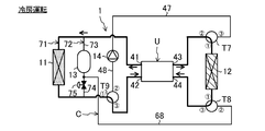
- Embodiment 1 The magnetic refrigeration apparatus (1) of the present embodiment adjusts the temperature of the heat medium by utilizing the magnetic calorific value effect.
- the magnetic refrigerating device (1) is a solid refrigerating device that adjusts the temperature of the heat medium by utilizing the calorific value effect.
- the magnetic refrigeration system (1) is applied to, for example, an air conditioner.
- the magnetic refrigeration system (1) regulates the temperature of the air in the space to be air-conditioned.
- the space to be air-conditioned is an indoor space.
- the magnetic refrigeration system (1) switches between cooling operation and heating operation.
- the magnetic refrigeration apparatus (1) includes a heat medium circuit (C) filled with a heat medium.
- the filled heat medium is conveyed.
- the heat medium includes, for example, a refrigerant, water, brine and the like.
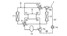
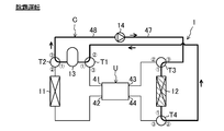
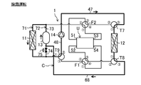
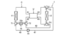
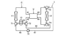
- the magnetic refrigeration system (1) includes a magnetic refrigeration unit (U), an indoor heat exchanger (11), an outdoor heat exchanger (12), a tank (13), a pump (14), and a switching mechanism (15). ) And a control device (100).
- the indoor heat exchanger (11) corresponds to the first heat exchanger and the outdoor heat exchanger (12) corresponds to the second heat exchanger.
- the tank (13) corresponds to the heat storage section.
- the pump (14) corresponds to the transport section.
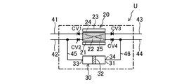
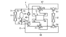
- the magnetic refrigeration unit (U) includes a magnetic refrigeration section (20) as a solid refrigeration section, a reciprocating pump (30), a first outflow pipe (41), and a first inflow pipe ( It has a 42), a second outflow pipe (43), a second inflow pipe (44), a first pump side pipe (45), and a second pump side pipe (46).
- the first outflow pipe (41) corresponds to the first outflow portion
- the first inflow pipe (42) corresponds to the first inflow portion.
- the second outflow pipe (43) corresponds to the second outflow portion
- the second inflow pipe (44) corresponds to the second outflow portion.
- the magnetic refrigeration section (20) has a bed (21), a magnetic working substance (22) as a solid working substance, and a magnetic field modulation section (23) as an inducing section.
- the bed (21) is a hollow case or column.
- the inside of the bed (21) is filled with a magnetic working substance (22).
- the magnetic working substance (22) generates heat when a magnetic field is applied or when the applied magnetic field becomes stronger.
- the magnetic working substance (22) absorbs heat when the magnetic field is removed or the applied magnetic field weakens.
- Examples of the material of the magnetic working substance (22) include Gd 5 (Ge 0.5 Si 0.5 ) 4 , La (Fe 1-x Si x ) 13 , La (Fe 1-x Co x Si y ) 13 , and La (Fe 1-x Si y) 13. 1-x Si x ) 13 Hy , Mn (As 0.9 Sb 0.1 ) and the like can be used.
- the magnetic refrigeration unit (20) of this embodiment is a single layer type.
- the magnetic refrigeration unit (20) is composed of one kind of magnetic working substance (22).
- This one type of magnetic working substance (22) has a relationship between the temperature and the magnetic freezing effect, for example, as shown in curve A in FIG.
- the Curie temperature of this one type of magnetic working substance (22) is preferably set to the average temperature of the heat medium flowing through each internal flow path (24, 25).
- the Curie temperature is the temperature at which the magnetic freezing effect of the magnetic working substance is maximized.
- the magnetic field modulator (23) adjusts the strength of the magnetic field applied to the magnetic working substance (22).
- the magnetic field modulation section (33) is a trigger section that induces a calorific value effect on a magnetic working substance (22) as a solid refrigerant substance.
- the magnetic field modulator (23) is composed of, for example, an electromagnet capable of modulating the magnetic field.
- the magnetic field modulation unit (23) performs the first modulation operation and the second modulation operation. In the first modulation operation, a magnetic field is applied to the magnetic working substance (22), or the applied magnetic field is strengthened. In the second modulation operation, the magnetic field applied to the magnetic working substance (22) is removed or the applied magnetic field is weakened.
- a first internal flow path (24) and a second internal flow path (25) are formed inside the bed (21).
- a first outflow pipe (41) is connected to one end of the first internal flow path (24).
- a second inflow pipe (44) is connected to the other end of the first internal flow path (24).
- a first inflow pipe (42) is connected to one end of the second internal flow path (25).
- a second outflow pipe (43) is connected to the other end of the second internal flow path (25).
- the first check valve (CV1) is provided in the first outflow pipe (41).
- a second check valve (CV2) is provided in the first inflow pipe (42).
- the second outflow pipe (43) is provided with a third check valve (CV3).
- the second inflow pipe (44) is provided with a fourth check valve (CV4).
- the first check valve (CV1) allows the flow of heat medium in the direction from the first internal flow path (24) of the magnetic refrigeration section (20) toward the indoor heat exchanger (11), and heat in the opposite direction. Prohibit the flow of media.
- the second check valve (CV2) allows the flow of heat medium in the direction from the indoor heat exchanger (11) to the second internal flow path (25) of the magnetic refrigeration section (20), and heat in the opposite direction. Prohibit the flow of media.
- the third check valve (CV3) allows the flow of heat medium in the direction from the second internal flow path (25) of the magnetic refrigeration section (20) to the outdoor heat exchanger (12), and heat in the opposite direction. Prohibit the flow of media.
- the fourth check valve (CV4) allows the flow of heat medium in the direction from the outdoor heat exchanger (12) to the second internal flow path (25) of the magnetic refrigeration section (20), and heat in the opposite direction. Prohibit the flow of media.
- the reciprocating pump (30) reciprocally conveys the heat medium of the heat medium circuit (C).
- the reciprocating pump (30) corresponds to the reciprocating transport mechanism.
- the reciprocating pump (30) is composed of a piston pump.
- the reciprocating pump (30) has a pump case (31), a piston (32), and a drive mechanism (not shown).
- the piston (32) is located inside the pump case (31).
- the piston (32) divides the inside of the pump case (31) into two chambers.
- the reciprocating pump (30) is provided with a first port (33) and a second port (34). One chamber of the pump case (31) communicates with the first port (33) and the other chamber communicates with the second port (34).
- One end of the first pump side pipe (45) is connected to the first port (33).
- the other end of the first pump side pipe (45) is connected to the upstream side of the second check valve (CV2) of the first inflow pipe (42).
- One end of the second pump side pipe (46) is connected to the second port (34).
- the other end of the second pump side pipe (46) is connected to the upstream side of the fourth check valve (CV4) of the second inflow pipe (44).
- the drive mechanism has a rod connected to the piston (32), a crank connected to the rod, and an electric motor for driving the crank.
- the electric motor rotates and drives the crank, the rod moves forward and backward.
- the reciprocating motion of the piston (32) is performed in the pump case (31).
- the first transfer operation and the second transfer operation are alternately and repeatedly performed.
- the piston (32) moves to the first port (33) side.
- the heat medium is discharged from the first port (33).
- the discharged heat medium flows through the first inflow pipe (42), the second internal flow path (25), and the second outflow pipe (43) in this order.
- the piston (32) moves to the second port (34) side.
- the heat medium is discharged from the second port (34).
- the discharged heat medium flows through the second inflow pipe (44), the first internal flow path (24), and the first outflow pipe (41) in this order.
- the indoor heat exchanger (11) shown in FIG. 1 is a utilization heat exchanger.
- the indoor heat exchanger (11) exchanges heat between the heat medium and the indoor air.
- One end of the indoor heat exchanger (11) is connected to the first outflow pipe (41) via a pipe.
- the other end of the indoor heat exchanger (11) is connected to the third port of the first three-way valve (T1) via a pipe.
- the outdoor heat exchanger (12) is a heat source heat exchanger.
- the outdoor heat exchanger (12) exchanges heat between the heat medium and the outdoor air.
- One end of the outdoor heat exchanger (12) is connected to the first port of the third three-way valve (T3) via a pipe.
- the other end of the outdoor heat exchanger (12) is connected to the first port of the fourth three-way valve (T4) via a pipe.
- the tank (13) is a container for storing a heat medium.
- the tank (13) has two ports. One of these ports is connected to the first port of the first three-way valve (T1) via a pipe. The other of these ports is connected to the first port of the second three-way valve (T2) via a pipe.
- the tank (13) is arranged on the downstream side of the indoor heat exchanger (11) in the heating operation.
- the pump (14) carries the heat medium. Specifically, in the defrosting operation described in detail later, the pump (14) conveys the heat medium in the tank (13) to the outdoor heat exchanger (12) to be defrosted.
- One end of the discharge pipe (47) is connected to the discharge side of the pump (14). The other end of the discharge pipe (47) is connected to the third port of the third three-way valve (T3).
- One end of the suction pipe (48) is connected to the suction side of the pump (14). The other end of the suction pipe (48) is connected to the second port of the first three-way valve (T1).
- the switching mechanism switches the flow path of the heat medium of the heat medium circuit (C).
- the switching mechanism switches the flow path of the heat medium at least in the heating operation and the defrosting operation.
- the switching mechanism (15) of the present embodiment switches the flow path of the heat medium in the cooling operation, the heating operation, and the defrosting operation.
- the switching mechanism (15) is composed of various valves.
- the switching mechanism (15) includes a first three-way valve (T1), a second three-way valve (T2), a third three-way valve (T3), and a fourth three-way valve (T4).
- Each three-way valve (T1, T2, T3, T4) has a first port, a second port, and a third port, respectively.
- the first port of the three-way valve is a symbol with a circle around 1
- the second port of the three-way valve is a symbol with a circle around 2
- the third port of the three-way valve is a circle with a circle of 3. It is a symbol.
- Each three-way valve switches between the first state (the state shown by the solid line in FIG. 1) and the second state (the state shown by the broken line in FIG. 1).
- Each of the three-way valves (T1, T2, T3, T4) in the first state communicates the first port and the second port.
- Each of the three-way valves (T1, T2, T3, T4) in the second state communicates the first port and the third port.
- the first port of the first three-way valve (T1) communicates with the tank (13).
- the second port of the first three-way valve (T1) communicates with the suction pipe (48).
- the third port of the first three-way valve (T1) communicates with the indoor heat exchanger (11).
- the first port of the second three-way valve (T2) communicates with the tank (13).
- the second port of the second three-way valve (T2) communicates with the first inflow pipe (42).
- One end of the relay pipe (49) is connected to the third port of the second three-way valve (T2).
- the first port of the third three-way valve (T3) communicates with the outdoor heat exchanger (12).
- the second port of the third three-way valve (T3) communicates with the second outflow pipe (43).
- the third port of the third three-way valve (T3) communicates with the discharge pipe (47).
- the 1st port of the 4th three-way valve (T4) communicates with the outdoor heat exchanger (12).
- the other end of the relay pipe (49) is connected to the second port of the fourth three-way valve (T4).
- the third port of the fourth three-way valve (T4) communicates with the second inflow pipe (44).
- the control device (100) controls the magnetic refrigeration device (1).
- the control device (100) is configured by using a microcomputer and a memory device (specifically, a semiconductor memory) for storing software for operating the microcomputer.
- control device (100) is connected to the magnetic refrigeration unit (U), the pump (14), and the switching mechanism (15) via a communication line.
- the control device (100) controls the magnetic field modulator (23), the reciprocating pump (30), the pump (14), and the switching mechanism (15), respectively.
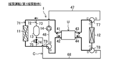
- the magnetic refrigerating device (1) performs a cooling operation, a heating operation, and a defrosting operation.
- the cooling operation the air in the indoor space is cooled.
- the cooling operation corresponds to the cooling operation.
- the heating operation the air in the indoor space is heated.
- the heating operation corresponds to the heating operation.
- the defrosting operation the frost in the outdoor heat exchanger (12) is melted.
- the first modulation operation of the magnetic field modulation unit (23) and the first transfer operation of the reciprocating pump (30) are performed at the same time.
- the heat medium is heated in the second internal flow path (25) of the magnetic refrigeration unit (20).
- the heated heat medium flows out of the second outflow pipe (43).
- the heat medium of the heat medium circuit (C) flows into the second port (34) of the pump case (31).
- the second modulation operation of the magnetic field modulation unit (23) and the second transfer operation of the reciprocating pump (30) are performed at the same time.
- the heat medium is cooled in the first internal flow path (24) of the magnetic refrigeration unit (20).
- the cooled heat medium flows out of the first outflow pipe (41).
- the heat medium of the heat medium circuit (C) flows into the first port (33) of the pump case (31).
- the first operation and the second operation are alternately repeated every second or so.
- the first three-way valve (T1) is in the second state
- the second three-way valve (T2) is in the first state
- the third three-way valve (T3) is in the first state
- the fourth three-way valve is in the first state.
- the valves (T4) are set to the second state respectively.
- the pump (14) stops.
- the switching mechanism (15) causes the heat medium cooled by the magnetic refrigeration section (20) to flow through the first outflow pipe (41), the indoor heat exchanger (11), and the first inflow pipe (42).
- the heat medium heated by the magnetic refrigeration section (20) forms a flow path through the second outflow pipe (43), the outdoor heat exchanger (12), and the second inflow pipe (44).
- the drawings show the flow of the heat medium in the first operation and the second operation in the same figure. Further, in the drawing, of the first heat exchanger (11) and the second heat exchanger (12), the heat exchanger through which the heat medium dissipates heat is hatched, and the heat exchanger on which the heat medium absorbs heat is marked with dots. are doing.
- the heat medium heated by the magnetic refrigeration unit (U) passes through the third three-way valve (T3) and flows through the outdoor heat exchanger (12). In the outdoor heat exchanger (12), the heat medium dissipates heat to the outdoor air. The heat medium radiated by the outdoor heat exchanger (12) passes through the fourth three-way valve (T4) and returns to the magnetic refrigeration unit (U).
- the heat medium cooled by the magnetic refrigeration unit (U) flows through the indoor heat exchanger (11).
- the heat medium absorbs heat from the indoor air.
- the indoor air is cooled.
- the heat medium absorbed by the indoor heat exchanger (11) passes through the first three-way valve (T1), the tank (13), and the second three-way valve (T2), and returns to the magnetic refrigeration unit (U).
- the second modulation operation of the magnetic field modulation unit (23) and the first transfer operation of the reciprocating pump (30) are performed at the same time.
- the heat medium is cooled in the second internal flow path (25) of the magnetic refrigeration unit (20).
- the cooled heat medium flows out of the second outflow pipe (43).
- the heat medium of the heat medium circuit (C) flows into the second port (34) of the pump case (31).
- the first modulation operation of the magnetic field modulation unit (23) and the second transfer operation of the reciprocating pump (30) are performed at the same time.
- the heat medium is heated in the first internal flow path (24) of the magnetic refrigeration unit (20).
- the heated heat medium flows out of the first outflow pipe (41).
- the heat medium of the heat medium circuit (C) flows into the first port (33) of the pump case (31).
- the first operation and the second operation are alternately repeated every second.
- the first three-way valve (T1) is in the second state
- the second three-way valve (T2) is in the first state
- the third three-way valve (T3) is in the first state
- the fourth three-way valve (T4) is set to the second state, respectively.
- the pump (14) stops.
- the switching mechanism (15) has the heat medium heated by the magnetic refrigeration section (20) as the first outflow pipe (41), the indoor heat exchanger (11), the tank (13) which is the heat storage section, and the first.
- the heat medium cooled by the magnetic refrigeration section (20) flows through the second outflow pipe (43), the outdoor heat exchanger (12), and the second inflow pipe (44).
- the heat medium cooled by the magnetic refrigerating section (20) in the third operation is endothermic by the outdoor heat exchanger (12), and the heat medium heated by the magnetic refrigerating section (20) in the third operation is used. Heat is dissipated by the indoor heat exchanger (11).
- the heat medium cooled by the magnetic refrigeration unit (U) passes through the third three-way valve (T3) and flows through the outdoor heat exchanger (12). In the outdoor heat exchanger (12), the heat medium absorbs heat from the outdoor air. The heat medium absorbed by the outdoor heat exchanger (12) passes through the fourth three-way valve (T4) and returns to the magnetic refrigeration unit (U).
- the heat medium heated by the magnetic refrigeration unit (U) flows through the indoor heat exchanger (11).
- the heat medium dissipates heat to the indoor air.
- the heat medium radiated by the indoor heat exchanger (11) passes through the first three-way valve (T1), the tank (13), and the second three-way valve (T2), and returns to the magnetic refrigeration unit (U).
- the heat medium heated by the magnetic refrigeration unit (U) is stored in the tank (13).
- the tank (13) stores the heat medium heated by the magnetic refrigeration unit (U).
- the tank (13) is located downstream of the indoor heat exchanger (11). Therefore, it is possible to suppress a decrease in the heating capacity of the indoor heat exchanger (11) due to the heat of the heat medium being stored in the tank (13). In particular, it is possible to suppress a decrease in the heating capacity at the start of the heating operation.
- the heat medium absorbs heat from the outdoor air in the outdoor heat exchanger (12). Therefore, frost may form on the surface of the outdoor heat exchanger (12).
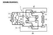
- the defrosting operation is performed when the condition indicating that the surface of the outdoor heat exchanger (12) is frosted is satisfied.
- the magnetic refrigeration unit (U) In the defrosting operation shown in FIG. 9, the magnetic refrigeration unit (U) is stopped. In the defrosting operation, the first three-way valve (T1) is in the first state, the second three-way valve (T2) is in the second state, the third three-way valve (T3) is in the second state, and the fourth three-way valve (T4). ) Is set to the first state.
- the pump (14) operates.
- the switching mechanism (15) forms a flow path through which the heat medium of the tank (13), which is the heat storage unit, flows through the outdoor heat exchanger (12).
- This flow path is a circulation flow path including a pump (14), a discharge pipe (47), an outdoor heat exchanger (12), a relay pipe (49), a tank (13), and a suction pipe (48).
- the heat medium in the tank (13) passes through the first three-way valve (T1), the suction pipe (48), the discharge pipe (47), and the third three-way valve (T3) in that order, and the outdoor heat.
- the heat medium flowing inside the outdoor heat exchanger (12) melts the frost on the surface of the outdoor heat exchanger (12).
- the heat medium used for defrosting the outdoor heat exchanger (12) passes through the fourth three-way valve (T4) and returns to the tank (13).
- the heat stored in the tank (13) in the heating operation is used for defrosting the outdoor heat exchanger (12).
- Embodiment 1- The feature of this embodiment is the magnetic field modulation that imparts magnetic field fluctuation to the magnetic working material (22), the internal flow path (24,25) in which the magnetic working material (22) is arranged, and the magnetic working material (22).
- a magnetic refrigeration unit (20) having a unit (23), at least one first heat exchanger (11) (indoor heat exchanger), at least one second heat exchanger (12), and the first.
- the heat medium circuit (C) in which the heat exchanger (11), the second heat exchanger (12), and the internal flow paths (24, 25) are connected, and the heat medium of the heat medium circuit (C)
- a reciprocating transport mechanism (30) for reciprocating transport is provided, and the heat medium heated by the magnetic refrigerating section (20) is dissipated by the first heat exchanger (11) and cooled by the magnetic refrigerating section (20).
- a magnetic refrigeration apparatus that performs a heating operation in which the heat medium is absorbed by the second heat exchanger (12) and a defrosting operation in which the frost of the second heat exchanger (12) is melted. In the defrosting operation, the heat stored in the heat storage unit (13) is used to melt the frost in the second heat exchanger (12). is there.
- the heat of the heat medium in the heating operation (heating operation), can be stored in the heat storage unit (13).
- the heat stored in the heating operation can be used for defrosting the second heat exchanger (outdoor heat exchanger (12)), so that sufficient heat required for this defrosting can be secured.
- the heat storage unit includes a tank (13) for storing the heat medium heated by the magnetic refrigeration unit (20) in the heating operation, and the inside of the tank (13) in the defrosting operation. It is provided with a transport unit (14) (pump) for transporting the heat medium to the second heat exchanger (12).
- the heat of the heat medium in the heating operation, can be stored in the tank (13).
- the heat medium stored in the tank (13) during the heating operation can be transported to the outdoor heat exchanger (12) by the pump (14).
- the pump (14) As a result, sufficient heat required for defrosting the outdoor heat exchanger (12) can be secured.
- the size of the tank (13) can be appropriately changed according to the amount of heat required for defrosting the outdoor heat exchanger (12).
- the feature of this embodiment is that the heat medium heated by the magnetic refrigeration unit (20) flows through the indoor heat exchanger (11) and the heat storage unit (13) in the heating operation, and the heat storage unit (20) in the defrosting operation. It is provided with a switching mechanism (15) for switching the flow path of the heat medium circuit (C) so that the heat medium in 13) flows through the outdoor heat exchanger (12).
- the heating operation for storing the heat of the heat medium in the heat storage unit (13) and the defrosting operation for flowing the heat medium in the heat storage unit (13) to the outdoor heat exchanger (12) are switched. Can be done.
- the feature of this embodiment is that the heat storage unit (13) is arranged on the downstream side of the first heat exchanger (11) in the heat medium circuit (C) during the heating operation.
- the heat medium heated by the magnetic refrigeration section (20) flows through the indoor heat exchanger (11) and the heat storage section (13) in this order. Therefore, it is possible to suppress a decrease in the heating capacity of the indoor heat exchanger (11) due to the heat of the heat medium being stored in the heat storage unit (13).
- the temperature of the heat storage unit (13) may be low at the start of the heating operation.
- the start-up time of the heating operation may become long.
- the start-up time of the indoor heat exchanger (11) can be shortened.
- the feature of this embodiment is that the heat medium cooled by the magnetic refrigeration unit (20) is absorbed by the first heat exchanger (11) and the heat medium heated by the magnetic refrigeration unit (20) is subjected to the second heat exchange.
- the magnetic refrigerating unit (20) is a single-layer type composed of one kind of magnetic working material (22), and is configured to further perform a cooling operation for dissipating heat from the vessel (12), and the heat medium circuit (C).
- the switching mechanism (15) includes two inflow sections (44), and in the heating operation, the heat medium heated by the magnetic refrigeration section (20) is the first outflow section (41) and the first heat exchanger.
- the heat medium that flows through the heat storage section (13, 16) and the first inflow section (42) and is cooled by the magnetic refrigeration section (20) is the second outflow section (43) and the second outflow section (43). 2
- a flow path through the heat exchanger (12) and the second inflow section (44) is formed, and in the cooling operation, the heat medium cooled by the magnetic refrigeration section (20) is the first outflow section (41). )
- the first heat exchanger (11), and the first inflow section (42), and the heat medium heated by the magnetic refrigeration section (20) is the second outflow section (43) and the second.
- a flow path is formed through the heat exchanger (12) and the second inflow section (44), and in the defrosting operation, the heat medium of the heat storage section (13, 16) is the second heat exchanger (12). ) Is formed.
- the above-mentioned cooling operation, heating operation, and defrosting operation can be switched.
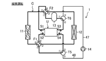
- ⁇ Modification 1 of Embodiment 1> In the first modification of the first embodiment, a so-called cascade type magnetic refrigeration unit (20) is used. As shown in FIGS. 10 and 11, the configuration of the magnetic refrigeration apparatus (1) of this modified example is different from the configuration of the magnetic refrigeration unit (U) and the heat medium circuit (C). The points that differ mainly from the embodiments will be described below.
- the magnetic refrigeration unit (U) has two magnetic refrigeration units (20). Specifically, the two magnetic refrigeration units (20) are composed of a first magnetic refrigeration unit (20A) and a second magnetic refrigeration unit (20B). Each magnetic refrigeration unit (20) has a bed (21) and a magnetic field modulation unit (23), respectively, as in the first embodiment. A first internal flow path (24) and a second internal flow path (25) are formed in each magnetic refrigeration unit (20), respectively.
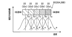
- the magnetic refrigeration section (20) of the modified example is a cascade type having a plurality of types of magnetic working substances (22). As shown in FIG. 12, the magnetic refrigeration section (20) of this example is composed of, for example, five types of magnetic working substances (22). In the magnetic refrigeration section (20), from the high temperature end to the low temperature end, the first magnetic working substance (22a), the second magnetic working substance (22b), the third magnetic working substance (22c), and the fourth magnetic working substance. (22d) and the fifth magnetic working substance (22e) are composed in this order.
- the temperature of each magnetic working substance (22) and the characteristics of the magnetic refrigeration effect are different from each other. Specifically, these magnetic working substances (22) have different Curie temperatures from each other.
- the Curie temperature of the first magnetic working material (22a) is Ta
- the Curie temperature of the second magnetic working material (22b) is Tb
- the Curie temperature of the third magnetic working material (22c) is Tc
- the curie temperature of the fourth magnetic working material (22d) Assuming that the Curie temperature is Td and the fifth magnetic working substance (22e) is Te, the relationship of Ta> Tb> Tc> Td> Te is satisfied.
- the magnetic refrigeration unit (U) has a low temperature outflow pipe (51), a low temperature inflow pipe (52), a high temperature outflow pipe (53), a high temperature inflow pipe (54), and a unit side pump (55).
- the magnetic refrigeration unit (U) has a low temperature first three-way valve (56), a low temperature second three-way valve (57), a high temperature first three-way valve (58), and a high temperature second three-way valve (59).
- the low temperature outflow pipe (51) corresponds to the low temperature outflow part
- the low temperature inflow pipe (52) corresponds to the low temperature inflow part.
- the high temperature outflow pipe (53) corresponds to the high temperature outflow part
- the high temperature inflow pipe (54) corresponds to the high temperature inflow part.
- the reciprocating transfer mechanism (50) is configured by these three-way valves (56,57,58,59) and the unit-side pump (55).
- the unit side pump (55) is installed in the high temperature outflow pipe (53).
- the unit-side pump (55) is a one-way pump.
- the unit-side pump (55) conveys the heat medium toward the downstream side of the high-temperature outflow pipe (53).
- each three-way valve (56,57,58,59) is the same as the configuration of the three-way valve described above.
- the first port of the low temperature first three-way valve (56) communicates with the low temperature outflow pipe (51).
- the second port of the low temperature first three-way valve (56) communicates with the low temperature end of the first internal flow path (24) of the second magnetic refrigeration section (20B).
- the third port of the low temperature first three-way valve (56) communicates with the low temperature end of the first internal flow path (24) of the first magnetic refrigeration section (20A).
- the first port of the low temperature second three-way valve (57) communicates with the low temperature inflow pipe (52).
- the second port of the low temperature second three-way valve (57) communicates with the low temperature end of the second internal flow path (25) of the second magnetic refrigeration section (20B).
- the third port of the low temperature second three-way valve (57) communicates with the low temperature end of the second internal flow path (25) of the first magnetic refrigeration section (20A).
- the first port of the high temperature first three-way valve (58) communicates with the high temperature outflow pipe (53).
- the second port of the high temperature first three-way valve (58) communicates with the high temperature end of the second internal flow path (25) of the second magnetic refrigeration section (20B).
- the third port of the high temperature first three-way valve (58) communicates with the high temperature end of the second internal flow path (25) of the first magnetic refrigeration section (20A).
- the first port of the high temperature second three-way valve (59) communicates with the high temperature inflow pipe (54).
- the second port of the high temperature second three-way valve (59) communicates with the high temperature end of the first internal flow path (24) of the second magnetic refrigeration section (20B).
- the third port of the high temperature second three-way valve (59) communicates with the high temperature end of the first internal flow path (24) of the first magnetic refrigeration section (20A).
- the switching mechanism (15) of this modified example includes a fifth three-way valve (T5), a sixth three-way valve (T6), a first four-way switching valve (F1), and a second four-way switching valve (T5).
- Has F2 The configuration of each three-way valve (T5) is the same as the configuration of the three-way valve described above.
- Each four-way switching valve (F1, F2) has a first port, a second port, a third port, and a fourth port, respectively.
- the first port of the four-way switching valve is a symbol with a circle around 1
- the second port of the four-way switching valve is a symbol with a circle around 2
- the third port of the four-way switching valve is a circle with a three. The symbol is circled, and the 4th port of the four-way switching valve is circled 4.
- Each four-way switching valve (F1, F2) switches between the first state (the state shown by the solid line in FIG. 1) and the second state (the state shown by the broken line in FIG. 1).
- Each of the four-way switching valves (F1 and F2) in the first state communicates the first port and the second port, and at the same time communicates the third port and the fourth port.
- Each of the four-way switching valves (F1 and F2) in the second state communicates the first port and the third port, and at the same time communicates the second port and the fourth port.
- the 1st port of the 5th three-way valve (T5) communicates with the tank (13).
- the second port of the fifth three-way valve (T5) communicates with the high temperature inflow pipe (54).
- the third port of the fifth three-way valve (T5) communicates with the suction pipe (48).
- the 1st port of the 6th three-way valve (T6) communicates with the outdoor heat exchanger (12).
- the second port of the sixth three-way valve (T6) communicates with the third port of the second four-way switching valve (F2).
- the third port of the sixth three-way valve (T6) communicates with the discharge pipe (47).
- the first port of the first four-way switching valve (F1) communicates with the tank (13).
- the second port of the first four-way switching valve (F1) communicates with the indoor heat exchanger (11).
- the third port of the first four-way switching valve (F1) communicates with the outdoor heat exchanger (12).
- the fourth port of the first four-way switching valve (F1) communicates with the low temperature inflow pipe (52).
- the first port of the second four-way switching valve (F2) communicates with the high temperature outflow pipe (53).
- the second port of the second four-way switching valve (F2) communicates with the indoor heat exchanger (11).
- the fourth port of the second four-way switching valve (F2) communicates with the low temperature outflow pipe (51).
- the magnetic refrigeration device (1) of this modified example has the same control device (100) as that of the embodiment.
- the configuration of the control device (100) is the same as that of the above embodiment. In FIG. 10 and other related drawings, the control device (100) is not shown.
- the magnetic refrigerating apparatus (1) of the first modification of the first embodiment performs a cooling operation, a heating operation, and a defrosting operation.
- the first magnetic refrigeration unit (20A) performs the first modulation operation
- the second magnetic refrigeration unit (20B) performs the second modulation operation.
- the low temperature first three-way valve (56) is in the first state
- the low temperature second three-way valve (57) is in the second state
- the high temperature first three-way valve (58) is in the second state
- the high temperature second three-way valve (59). are set to the first state respectively.
- the unit side pump (55) operates.
- the first magnetic refrigeration unit (20A) performs the second modulation operation
- the second magnetic refrigeration unit (20B) performs the first modulation operation.
- the low temperature first three-way valve (56) is in the second state
- the low temperature second three-way valve (57) is in the first state
- the high temperature first three-way valve (58) is in the first state
- the high temperature second three-way valve (59). are set to the second state respectively.
- the unit side pump (55) operates.
- the fifth three-way valve (T5) is in the first state
- the sixth three-way valve (T6) is in the first state
- the first four-way switching valve (F1) is in the second state.
- the second four-way switching valve (F2) is set to the second state.
- the switching mechanism (15) allows the heat medium cooled by each magnetic refrigeration unit (20) to flow through the low temperature outflow pipe (51), the indoor heat exchanger (11), and the low temperature inflow pipe (52).
- the heat medium heated by each magnetic refrigeration unit (20) forms a flow path through the high temperature outflow pipe (53), the outdoor heat exchanger (12), and the high temperature inflow pipe (54).
- the heat medium heated by the magnetic refrigeration unit (U) passes through the second four-way switching valve (F2) and the sixth three-way valve (T6), and flows through the outdoor heat exchanger (12).
- the heat medium dissipates heat to the outdoor air.
- the heat medium radiated by the outdoor heat exchanger (12) passes through the first four-way switching valve (F1), the tank (13), and the fifth three-way valve (T5), and returns to the magnetic refrigeration unit (U).
- the heat medium cooled by the magnetic refrigeration unit (U) passes through the second four-way switching valve (F2) and flows through the indoor heat exchanger (11).
- the heat medium absorbs heat from the indoor air.
- the indoor air is cooled.
- the heat medium absorbed by the indoor heat exchanger (11) passes through the first four-way switching valve (F1) and returns to the magnetic refrigeration unit (U).
- the fifth three-way valve (T5) is in the first state
- the sixth three-way valve (T6) is in the first state
- the first four-way switching valve (F1) is in the first state.
- the second four-way switching valve (F2) is set to the first state.
- the switching mechanism (15) uses the heat medium heated by each magnetic refrigeration unit (20) as a high-temperature outflow pipe (53), indoor heat exchanger (11), tank (13), and high-temperature inflow pipe (54). ), And the heat medium cooled by each magnetic refrigeration unit (20) forms a flow path through the low temperature outflow pipe (51), the outdoor heat exchanger (12), and the low temperature inflow pipe (52).
- the heat medium cooled by the magnetic refrigeration unit (U) passes through the second four-way switching valve (F2) and the sixth three-way valve (T6), and flows through the outdoor heat exchanger (12).
- the heat medium absorbs heat from the outdoor air.
- the heat medium absorbed by the outdoor heat exchanger (12) passes through the first four-way switching valve (F1) and returns to the magnetic refrigeration unit (U).
- the heat medium heated by the magnetic refrigeration unit (U) passes through the second four-way switching valve (F2) and flows through the indoor heat exchanger (11).
- the heat medium dissipates heat to the indoor air.
- the heat medium radiated by the indoor heat exchanger (11) passes through the first four-way switching valve (F1), the tank (13), and the fifth three-way valve (T5), and returns to the magnetic refrigeration unit (U).
- the heat medium heated by the magnetic refrigeration unit (U) is stored in the tank (13).
- the tank (13) stores the heat of the heat medium heated by the magnetic refrigeration unit (U).
- the switching mechanism (15) forms a flow path through which the heat medium of the tank (13), which is the heat storage unit, flows through the outdoor heat exchanger (12).
- This flow path is a circulation flow path including a pump (14), a discharge pipe (47), an outdoor heat exchanger (12), a tank (13), and a suction pipe (48).
- the heat medium in the tank (13) passes through the fifth three-way valve (T5), the suction pipe (48), the discharge pipe (47), and the sixth three-way valve (T6) in this order. , Flows through the outdoor heat exchanger (12). In the outdoor heat exchanger (12), the heat medium flowing inside the outdoor heat exchanger (12) melts the frost on the surface of the outdoor heat exchanger (12). The heat medium used for defrosting the outdoor heat exchanger (12) passes through the first four-way switching valve (F1) and returns to the tank (13).
- the heat stored in the tank (13) in the heating operation is used for defrosting the outdoor heat exchanger (12).
- the feature of this embodiment is that the heat medium cooled by the magnetic refrigeration unit (20) is absorbed by the first heat exchanger (11) and the heat medium heated by the magnetic refrigeration unit (20) is subjected to the second heat exchange.
- the magnetic refrigerating section (20) is a cascade type composed of a plurality of types of magnetic working materials (22), and the heat medium circuit (C) is configured to further perform a cooling operation in which heat is dissipated by the vessel (12).
- the switching mechanism (15) includes the high temperature outflow portion (53), the first heat exchanger (11), and the heat medium heated by the magnetic refrigeration unit (20).
- the heat medium that flows through the heat storage section (13, 16) and the high temperature inflow section (54) and is cooled by the magnetic refrigeration section (20) is the low temperature outflow section (51) and the second heat exchanger (12).
- the heat medium cooled by the magnetic refrigeration section (20) in the cooling operation is formed by the low temperature outflow section (51) and the first heat exchanger (1st heat exchanger).
- the heat medium heated by the magnetic refrigeration section (20) flows through the low temperature inflow section (52) and the high temperature outflow section (53), the second heat exchanger (12), and the high temperature inflow section.
- a flow path through the section (54) is formed, and in the defrosting operation, the heat medium of the heat storage section (13, 16) forms a flow path through the second heat exchanger (12).
- the above-mentioned cooling operation, heating operation, and defrosting operation can be switched.
- the second modification of the first embodiment has a different configuration of the heat medium circuit (C) from the first embodiment.
- the configuration of the magnetic refrigeration unit (U) of this modification is the same as the configuration of the first embodiment.
- the magnetic refrigeration section (20) of this modification is a single-layer type.
- the first three-way valve (T1), the tank (13), and the second three-way valve (T2) are indoor heat exchangers. It is located on the upstream side of (11).
- the first three-way valve (T1) is in the second state
- the second three-way valve (T2) is in the first state
- the third three-way valve (T3) is in the first state
- the fourth three-way valve is in the first state.
- the valves (T4) are set to the second state respectively.
- the magnetic refrigeration unit (U) alternately performs the third operation and the fourth operation.
- the pump (14) stops.
- the heat medium heated by the magnetic refrigeration unit (U) passes through the first three-way valve (T1), the tank (13), and the second three-way valve (T2), and flows through the indoor heat exchanger (11).
- the tank (13) is located upstream of the indoor heat exchanger (11). Therefore, the heat of the heat medium can be reliably stored in the tank (13).
- the heat medium radiated by the indoor heat exchanger (11) returns to the magnetic refrigeration unit (U).
- the heat medium cooled by the magnetic refrigeration unit (U) passes through the third three-way valve (T3) and absorbs heat in the outdoor heat exchanger (12). This heat medium passes through the fourth three-way valve (T4) and returns to the magnetic refrigeration unit (U).
- the first three-way valve (T1) is in the first state
- the second three-way valve (T2) is in the second state
- the third three-way valve (T3) is in the second state
- the three-way valve (T4) is set to the first state respectively.
- the magnetic refrigeration unit (U) stops.
- the pump (14) operates.
- the heat medium in the tank (13) passes through the second three-way valve (T2), the suction pipe (48), the discharge pipe (47), and the third three-way valve (T3) in this order, and passes through the outdoor heat exchanger (12). It flows. In the outdoor heat exchanger (12), the heat medium melts the frost.
- the heat medium used for defrosting the outdoor heat exchanger (12) passes through the fourth three-way valve (T4) and the first three-way valve (T1) and returns to the tank (13).
- the modified example 3 of the first embodiment has a different configuration of the heat medium circuit (C) from the modified example 1 of the first embodiment.
- the configuration of the magnetic refrigeration unit (U) of this modification is the same as the configuration of modification 1 of the first embodiment.
- the magnetic refrigeration section (20) of this modification is a cascade type. As shown in FIG. 19, in the heat medium circuit (C) of this modified example, in the heating operation, the sixth three-way valve (T6), the tank (13), and the second four-way switching valve (F2) exchange indoor heat. It is placed on the upstream side of the vessel (11).
- the fifth three-way valve (T5) is in the first state
- the sixth three-way valve (T6) is in the first state
- the first four-way switching valve (F1) is in the first state
- the second state is in the first state
- the four-way switching valve (F2) is set to the first state respectively.
- the magnetic refrigeration unit (U) alternately performs the fifth operation and the sixth operation.
- the pump (14) stops.
- the heat medium heated by the magnetic refrigeration unit (U) passes through the 6th three-way valve (T6), the tank (13), and the 2nd four-way switching valve (F2), and flows through the indoor heat exchanger (11).
- the tank (13) is located upstream of the indoor heat exchanger (11). Therefore, the heat of the heat medium can be reliably stored in the tank (13).
- the heat medium radiated by the indoor heat exchanger (11) passes through the first four-way switching valve (F1) and the fifth three-way valve (T5) in this order, and returns to the magnetic refrigeration unit (U).
- the heat medium cooled by the magnetic refrigeration unit (U) passes through the second four-way switching valve (F2) and absorbs heat in the outdoor heat exchanger (12). This heat medium passes through the first four-way switching valve (F1) and returns to the magnetic refrigeration unit (U).
- the fifth three-way valve (T5) is in the second state
- the sixth three-way valve (T6) is in the second state
- the first four-way switching valve (F1) is in the second state.
- the four-way switching valve (F2) is set to the second state, respectively.
- the magnetic refrigeration unit (U) stops.
- the pump (14) operates.
- the heat medium in the tank (13) passes through the second four-way switching valve (F2) and flows through the outdoor heat exchanger (12). In the outdoor heat exchanger (12), the heat medium melts the frost.
- the heat medium used for defrosting the outdoor heat exchanger (12) passes through the first four-way switching valve (F1), the fifth three-way valve (T5), and the sixth three-way valve (T6), and passes through the tank (13).
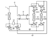
- the magnetic refrigeration apparatus (1) according to the second embodiment has a plurality of outdoor heat exchangers (12). In the defrosting operation, a defrosting operation is performed in which a plurality of outdoor heat exchangers (12) are individually defrosted.
- the configuration of the magnetic refrigeration unit (U) of the second embodiment is the same as the configuration of the first embodiment.
- the magnetic refrigeration unit (U) has a single-layer magnetic refrigeration unit (20).
- the switching mechanism (15) of the second embodiment is a third four-way switching valve (F3), a fourth four-way switching valve (F4), a first suction three-way valve (61), and a first discharge three-way valve. (62), a second suction three-way valve (63), and a second discharge three-way valve (64) are included.
- the first port of the third four-way switching valve (F3) communicates with each second port of the first discharge three-way valve (62) and the second discharge three-way valve (64) via the first relay pipe (65). ..
- the second port (34) of the third four-way switching valve (F3) communicates with the tank (13).
- the third port of the third four-way switching valve (F3) communicates with the indoor heat exchanger (11).
- the fourth port of the third four-way switching valve (F3) communicates with the second port of the fourth four-way switching valve (F4) via the bypass pipe (66).
- the bypass pipe (66) corresponds to the bypass flow path that bypasses the tank (13) in the first heating operation.
- the first port of the fourth four-way switching valve (F4) communicates with each third port of the first suction three-way valve (61) and the second suction three-way valve (63) via the second relay pipe (67). ..
- the third port of the fourth four-way switching valve (F4) communicates with the first inflow pipe (42).
- the fourth port of the fourth four-way switching valve (F4) communicates with the tank (13).
- the two outdoor circuits are connected in parallel to the heat medium circuit (C).
- the two outdoor circuits are composed of a first outdoor circuit (OC1) and a second outdoor circuit (OC2).
- the heat medium circuit (C) may have three or more outdoor circuits.
- the first outdoor circuit (OC1) is provided with a first outdoor heat exchanger (12A), a first pump (14A), a first suction three-way valve (61), and a first discharge three-way valve (62). Be done.
- the first outdoor heat exchanger (12A) is arranged on the discharge side of the first pump (14A).
- the first suction three-way valve (61) is arranged on the suction side of the first pump (14A).
- the first port of the first suction three-way valve (61) communicates with the first pump (14A).
- the second port of the first suction three-way valve (61) communicates with the second outflow pipe (43).
- the first port of the first discharge three-way valve (62) communicates with the first outdoor heat exchanger (12A).
- the third port of the first discharge three-way valve (62) communicates with the second inflow pipe (44).
- the second outdoor circuit (OC2) is provided with a second outdoor heat exchanger (12B), a second pump (14B), a second suction three-way valve (63), and a second discharge three-way valve (64). Be done.
- the second outdoor heat exchanger (12B) is arranged on the discharge side of the second pump (14B).
- a second suction three-way valve (63) is arranged on the suction side of the second pump (14B).
- the first port of the second suction three-way valve (63) communicates with the second pump (14B).
- the second port of the second suction three-way valve (63) communicates with the second outflow pipe (43).
- the first port of the second discharge three-way valve (64) communicates with the second outdoor heat exchanger (12B).
- the third port of the second discharge three-way valve (64) communicates with the second inflow pipe (44).
- the magnetic refrigerating apparatus (1) of the second embodiment performs a cooling operation, a heating operation, and a defrosting operation.
- the heating operation includes a first heating operation and a second heating operation.
- the defrosting operation includes a first defrosting operation and a second defrosting operation.
- the third four-way switching valve (F3) is in the first state
- the fourth four-way switching valve (F4) is in the second state
- the first suction three-way valve (61) is in the first state.
- the first discharge three-way valve (62) is set to the second state
- the second suction three-way valve (63) is set to the first state
- the second discharge three-way valve (64) is set to the second state.
- the first pump (14A) and the second pump (14B) are stopped.
- the first pump (14A) and the second pump (14B) may be operated.
- the heat medium heated by the magnetic refrigeration unit (U) flows in parallel with the first outdoor circuit (OC1) and the second outdoor circuit (OC2).
- the first outdoor circuit (OC1) the heat medium passes through the first suction three-way valve (61) and dissipates heat in the first outdoor heat exchanger (12A).
- the heat medium radiated by the first outdoor heat exchanger (12A) passes through the first discharge three-way valve (62) and returns to the magnetic refrigeration unit (U).
- the heat medium passes through the second suction three-way valve (63) and dissipates heat in the second outdoor heat exchanger (12B).
- the heat medium radiated by the second outdoor heat exchanger (12B) passes through the second discharge three-way valve (64) and returns to the magnetic refrigeration unit (U).
- the heat medium cooled by the magnetic refrigeration unit (U) flows through the indoor heat exchanger (11).
- the heat medium absorbs heat from the indoor air.
- the heat medium absorbed by the indoor heat exchanger (11) flows through the third four-way switching valve (F3), the bypass pipe (66), and the fourth four-way switching valve (F4), and returns to the magnetic refrigeration unit (U).
- the heating operation includes a first heating operation and a second heating operation.
- the first heating operation is executed at the start of the heating operation.
- the first heating operation is executed in a period after the command for executing the heating operation is received by the control device (100) until the condition for the heating operation to reach the steady operation is satisfied.
- This condition is, for example, that the suction temperature of the indoor heat exchanger (11) reaches a predetermined temperature.
- the second heating operation is executed.
- the third four-way switching valve (F3) is in the first state
- the fourth four-way switching valve (F4) is in the second state
- the first suction three-way valve (61) is in the first state.
- the first discharge three-way valve (62) is set to the second state
- the second suction three-way valve (63) is set to the first state
- the second discharge three-way valve (64) is set to the second state.
- the first pump (14A) and the second pump (14B) are stopped.
- the first pump (14A) and the second pump (14B) may be operated.
- the heat medium cooled by the magnetic refrigeration unit (U) flows in parallel with the first outdoor circuit (OC1) and the second outdoor circuit (OC2).
- the first outdoor circuit (OC1) the heat medium passes through the first suction three-way valve (61) and is endothermic in the first outdoor heat exchanger (12A).
- the heat medium absorbed by the first outdoor heat exchanger (12A) passes through the first discharge three-way valve (62) and returns to the magnetic refrigeration unit (U).
- the second outdoor circuit (OC2) the heat medium passes through the second suction three-way valve (63) and is endothermic in the second outdoor heat exchanger (12B).
- the heat medium absorbed by the second outdoor heat exchanger (12B) passes through the second discharge three-way valve (64) and returns to the magnetic refrigeration unit (U).
- the heat medium heated by the magnetic refrigeration unit (U) flows through the indoor heat exchanger (11).
- the heat medium dissipates heat to the indoor air.
- the heat medium radiated by the indoor heat exchanger (11) flows through the third four-way switching valve (F3), the bypass pipe (66), and the fourth four-way switching valve (F4), and returns to the magnetic refrigeration unit (U).
- the heat medium heated by the magnetic refrigeration unit (U) bypasses the tank (13) and returns to the magnetic refrigeration unit (U). Therefore, the heat of the heat medium is not stored in the tank (13). Therefore, the heating capacity of the indoor heat exchanger (11) can be quickly improved, and the start-up time of the heating operation can be shortened.
- the third four-way switching valve (F3) is in the second state
- the fourth four-way switching valve (F4) is in the first state
- the first suction three-way valve (61) is in the first state.
- the first discharge three-way valve (62) is set to the second state
- the second suction three-way valve (63) is set to the first state
- the second discharge three-way valve (64) is set to the second state.
- the first pump (14A) and the second pump (14B) are stopped.
- the first pump (14A) and the second pump (14B) may be operated.
- the heat medium cooled by the magnetic refrigeration unit (U) flows in parallel with the first outdoor circuit (OC1) and the second outdoor circuit (OC2).
- the first outdoor circuit (OC1) the heat medium passes through the first suction three-way valve (61) and is endothermic in the first outdoor heat exchanger (12A).
- the heat medium absorbed by the first outdoor heat exchanger (12A) passes through the first discharge three-way valve (62) and returns to the magnetic refrigeration unit (U).
- the second outdoor circuit (OC2) the heat medium passes through the second suction three-way valve (63) and is endothermic in the second outdoor heat exchanger (12B).
- the heat medium absorbed by the second outdoor heat exchanger (12B) passes through the second discharge three-way valve (64) and returns to the magnetic refrigeration unit (U).
- the heat medium heated by the magnetic refrigeration unit (U) flows through the indoor heat exchanger (11).
- the heat medium dissipates heat to the indoor air.
- the heat medium radiated by the indoor heat exchanger (11) flows through the tank (13).
- the heat of the heat medium is stored.
- the heat medium flowing through the tank (13) returns to the magnetic refrigeration unit (U).
- the defrosting operation includes a first defrosting operation and a second defrosting operation.
- the outdoor heat exchanger (12) to be defrosted and the outdoor heat exchanger (12) that absorbs heat from the heat medium are different from each other.
- the first defrosting operation and the second defrosting operation are performed at least once.
- the first outdoor heat exchanger (12A) is targeted for defrosting, and the heat medium absorbs heat in the second outdoor heat exchanger (12B).
- the second outdoor heat exchanger (12B) is targeted for defrosting, and the heat medium absorbs heat in the first outdoor heat exchanger (12A).
- the heat medium heated by the magnetic refrigeration unit (20) is dissipated by the indoor heat exchanger (11), and the heat medium cooled by the magnetic refrigeration unit (20) is dissipated by some outdoor heat exchangers (20).
- the operation of absorbing heat in 12) and the operation of supplying the heat medium of the tank (13) to the other outdoor heat exchanger (12) to be defrosted are executed at the same time.
- the third four-way switching valve (F3) is in the first state
- the fourth four-way switching valve (F4) is in the second state
- the first suction three-way valve (61) is in the second state.
- the first discharge three-way valve (62) is set to the first state
- the second suction three-way valve (63) is set to the first state
- the second discharge three-way valve (64) is set to the second state.
- the first pump (14A) operates.
- the second pump (14B) stops.
- the second pump (14B) may be operated.
- the heat medium cooled by the magnetic refrigeration unit (U) flows through the second outdoor circuit (OC2).
- the heat medium passes through the second suction three-way valve (63) and is endothermic in the second outdoor heat exchanger (12B).
- the heat medium absorbed by the second outdoor heat exchanger (12B) passes through the second discharge three-way valve (64) and returns to the magnetic refrigeration unit (U).
- the heat medium heated by the magnetic refrigeration unit (U) flows through the indoor heat exchanger (11).
- the heat medium dissipates heat to the indoor air.
- the heat medium radiated by the indoor heat exchanger (11) flows through the third four-way switching valve (F3), the bypass pipe (66), and the fourth four-way switching valve (F4), and returns to the magnetic refrigeration unit (U).
- the heat medium in the tank (13) passes through the 4th 4-way switching valve (F4) and the 1st suction 3-way valve (61), and flows through the 1st outdoor heat exchanger (12A).
- the heat medium flowing inside the first outdoor heat exchanger (12A) melts the frost on the surface of the first outdoor heat exchanger (12A).
- the heat medium used for defrosting the first outdoor heat exchanger (12A) passes through the first discharge three-way valve (62) and the third four-way switching valve (F3), and returns to the tank (13).
- the third four-way switching valve (F3) is in the first state
- the fourth four-way switching valve (F4) is in the second state
- the first suction three-way valve (61) is in the first state
- the first discharge three-way valve (62) is set to the second state
- the second suction three-way valve (63) is set to the second state
- the second discharge three-way valve (64) is set to the first state.
- the second pump (14B) operates.
- the first pump (14A) stops.
- the first pump (14A) may be operated.
- the heat medium cooled by the magnetic refrigeration unit (U) flows through the first outdoor circuit (OC1).
- the heat medium passes through the first suction three-way valve (61) and is endothermic in the first outdoor heat exchanger (12A).
- the heat medium absorbed by the first outdoor heat exchanger (12A) passes through the first discharge three-way valve (62) and returns to the magnetic refrigeration unit (U).
- the heat medium heated by the magnetic refrigeration unit (U) flows through the indoor heat exchanger (11).
- the heat medium dissipates heat to the indoor air.
- the heat medium radiated by the indoor heat exchanger (11) flows through the third four-way switching valve (F3), the bypass pipe (66), and the fourth four-way switching valve (F4), and returns to the magnetic refrigeration unit (U).
- the heat medium in the tank (13) passes through the 4th four-way switching valve (F4) and the second suction three-way valve (63), and flows through the second outdoor heat exchanger (12B).
- the heat medium flowing inside the second outdoor heat exchanger (12B) melts the frost on the surface of the second outdoor heat exchanger (12B).
- the heat medium used for defrosting the second outdoor heat exchanger (12B) passes through the second discharge three-way valve (64) and the third four-way switching valve (F3), and returns to the tank (13).
- the at least one second heat exchanger (12) is composed of a plurality of second heat exchangers (12), and the defrosting operation is the second heat exchanger to be defrosted. (12) and a plurality of defrosting operations for changing the second heat exchanger (12) for absorbing heat of the heat medium are included, and in each of the defrosting operations, the heat medium heated by the magnetic refrigerating unit (20) is described.
- the operation of supplying the heat medium of the heat storage unit (13, 16) to the second heat exchanger (12) is executed at the same time.
- the air can be heated by the first heat exchanger (11) while defrosting the second heat exchanger (12) to be defrosted.
- the outdoor heat exchanger (12) to be defrosted can be defrosted and the heating operation can be continued.
- the defrosting operation all the outdoor heat exchangers (12) can be defrosted by performing a plurality of defrosting operations.
- the magnetic refrigeration apparatus (1) of the first modification of the second embodiment shown in FIG. 27 has a so-called cascade type magnetic refrigeration unit (20).
- the configuration of the magnetic refrigeration unit (U) of the first modification of the second embodiment is the same as the configuration of the magnetic refrigeration unit (U) of the first modification of the first embodiment.
- the switching mechanism (15) of this modification has a first four-way switching valve (F1) and a second four-way switching valve (F2), as in the first modification of the first embodiment.
- the first port of the first four-way switching valve (F1) communicates with the third port of the third four-way switching valve (F3).
- the second port of the first four-way switching valve (F1) communicates with the indoor heat exchanger (11).
- the third port of the first four-way switching valve (F1) communicates with the low temperature inflow pipe (52).
- the fourth port of the first four-way switching valve (F1) communicates with the third port of the first discharge three-way valve (62) and the third port of the second discharge three-way valve (64), respectively.
- the first port of the second four-way switching valve (F2) communicates with the high temperature outflow pipe (53).
- the second port of the second four-way switching valve (F2) communicates with the indoor heat exchanger (11).
- the third port of the second four-way switching valve (F2) communicates with the low temperature outflow pipe (51).
- the fourth port of the second four-way switching valve (F2) communicates with the second port of the first suction three-way valve (61) and the second port of the second suction three-way valve (63), respectively.
- the other configurations of the magnetic refrigeration apparatus (1) of this modified example are basically the same as the configurations of the magnetic refrigeration apparatus (1) of the second embodiment.
- the magnetic refrigerating apparatus (1) of the first modification of the second embodiment performs a cooling operation, a heating operation, and a defrosting operation.
- the heating operation includes a first heating operation and a second heating operation.
- the defrosting operation includes a first defrosting operation and a second defrosting operation.
- the first four-way switching valve (F1) is in the second state
- the second four-way switching valve (F2) is in the second state
- the third four-way switching valve (F3) is in the first state.
- the four-way switching valve (F4) is in the second state
- the first suction three-way valve (61) is in the first state
- the first discharge three-way valve (62) is in the second state
- the second suction three-way valve (63) is in the second state.
- the second discharge three-way valve (64) is set in the second state, respectively.
- the first pump (14A) and the second pump (14B) are stopped.
- the first pump (14A) and the second pump (14B) may be operated.
- the heat medium absorbs heat in the indoor heat exchanger (11).
- the heat medium dissipates heat in the first outdoor heat exchanger (12A) and the second outdoor heat exchanger (12B), respectively.
- the heat medium heated by the magnetic refrigeration unit (U) bypasses the tank (13) and returns to the magnetic refrigeration unit (U).
- Heating operation is performed in the same manner as in the second embodiment.
- the first four-way switching valve (F1) is in the first state
- the second four-way switching valve (F2) is in the first state
- the third four-way switching valve (F3) is in the first state
- the 4th four-way switching valve (F4) is in the second state
- the first suction three-way valve (61) is in the first state
- the first discharge three-way valve (62) is in the second state
- the second suction three-way valve ( 63) is set to the first state
- the second discharge three-way valve (64) is set to the second state.
- the first pump (14A) and the second pump (14B) are stopped.
- the first pump (14A) and the second pump (14B) may be operated.
- the heat medium in the first heating operation, the heat medium dissipates heat in the indoor heat exchanger (11).
- the heat medium absorbs heat in the first outdoor heat exchanger (12A) and the second outdoor heat exchanger (12B), respectively.
- the heat medium heated by the magnetic refrigeration unit (U) bypasses the tank (13) and returns to the magnetic refrigeration unit (U). Thereby, as in the second embodiment, the start-up time of the heating operation can be shortened.
- the first four-way switching valve (F1) is in the first state
- the second four-way switching valve (F2) is in the first state
- the third four-way switching valve (F3) is in the second state
- the 4th four-way switching valve (F4) is in the first state
- the first suction three-way valve (61) is in the first state
- the first discharge three-way valve (62) is in the second state
- the second suction three-way valve ( 63) is set to the first state
- the second discharge three-way valve (64) is set to the second state.
- the first pump (14A) and the second pump (14B) are stopped.
- the first pump (14A) and the second pump (14B) may be operated.
- the heat medium dissipates heat in the indoor heat exchanger (11).
- the heat medium absorbs heat in the first outdoor heat exchanger (12A) and the second outdoor heat exchanger (12B), respectively.
- the heat medium heated by the magnetic refrigeration unit (U) passes through the tank (13) and returns to the magnetic refrigeration unit (U).
- the defrosting operation includes a first defrosting operation and a second defrosting operation.
- the outdoor heat exchanger (12) to be defrosted and the outdoor heat exchanger (12) that absorbs heat from the heat medium are different from each other.
- the first defrosting operation and the second defrosting operation are performed at least once.
- the first outdoor heat exchanger (12A) is targeted for defrosting, and the heat medium absorbs heat in the second outdoor heat exchanger (12B).
- the second outdoor heat exchanger (12B) is targeted for defrosting, and the heat medium absorbs heat in the first outdoor heat exchanger (12A).
- the heat medium heated by the magnetic refrigeration unit (20) is dissipated by the indoor heat exchanger (11), and the heat medium cooled by the magnetic refrigeration unit (20) is dissipated by some outdoor heat exchangers (20).
- the operation of absorbing heat in 12) and the operation of supplying the heat medium of the tank (13) to the other outdoor heat exchanger (12) to be defrosted are executed at the same time.
- the first four-way switching valve (F1) is in the first state
- the second four-way switching valve (F2) is in the first state
- the third four-way switching valve (F3) is in the first state
- the 4th four-way switching valve (F4) is in the second state
- the first suction three-way valve (61) is in the second state
- the first discharge three-way valve (62) is in the first state
- the second suction three-way valve. (63) is set to the first state
- the second discharge three-way valve (64) is set to the second state.
- the first pump (14A) operates.
- the second pump (14B) stops.
- the second pump (14B) may be operated.
- the heat medium absorbs heat in the second outdoor heat exchanger (12B), and the heat medium dissipates heat in the indoor heat exchanger (11). At the same time, the heat medium of the tank (13) dissipates heat in the first outdoor heat exchanger (12A), and the operation of returning to the tank (13) is performed.
- the first four-way switching valve (F1) is in the first state
- the second four-way switching valve (F2) is in the first state
- the third four-way switching valve (F3) is in the first state
- the 4th four-way switching valve (F4) is in the second state
- the first suction three-way valve (61) is in the first state
- the first discharge three-way valve (62) is in the second state
- the second suction three-way valve. (63) is set to the second state
- the second discharge three-way valve (64) is set to the first state.
- the second pump (14B) operates.
- the first pump (14A) stops.
- the first pump (14A) may be operated.
- the heat medium absorbs heat in the first outdoor heat exchanger (12A), and the heat medium dissipates heat in the indoor heat exchanger (11). At the same time, the heat medium of the tank (13) dissipates heat in the second outdoor heat exchanger (12B), and the operation of returning to the tank (13) is performed.
- the tank (13) may be arranged on the upstream side of the indoor heat exchanger (11) in the heating operation.
- the heat medium circuit (C) may have an outdoor heat exchanger (12) of N or more (N ⁇ 3).
- the number of outdoor heat exchangers to be defrosted is N (N ⁇ 3).
- a plurality of defrosting operations are performed so as to change the outdoor heat exchanger (12) to be defrosted.
- two or more outdoor heat exchangers (12) may be targeted for defrosting. For example, if the number of outdoor heat exchangers (12) is three, in one defrosting operation, two outdoor heat exchangers (12) are defrosted and the other one outdoor heat exchanger (12) heats up.
- the medium may be endothermic.
- Embodiment 3 In the heat medium circuit (C) of the magnetic refrigeration apparatus (1) of the third embodiment, the tank (13) and the indoor heat exchanger (11) are connected in parallel. It is the same as the configuration of the first embodiment.
- the magnetic refrigeration unit (U) has a single-layer magnetic refrigeration unit (20).
- the heat medium circuit (C) has a first flow path (71) and a second flow path (72).
- the first flow path (71) and the second flow path (72) are arranged in parallel with each other.
- An indoor heat exchanger (11) is provided in the first flow path (71).
- a tank (13) is provided in the second flow path (72).
- the first flow path (71) corresponds to a bypass flow path that bypasses the tank (13).
- One end of each of the first flow path (71) and the second flow path (72) communicates with the first outflow pipe (41).
- the other ends of each of the first flow path (71) and the second flow path (72) communicate with the first port of the ninth three-way valve (T9).
- the second flow path (72) includes the first pipe (73) and the second pipe (74). One end of the first pipe (73) is connected to the upper end of the tank (13). One end of the second pipe (74) is connected to the lower end of the tank (13).
- the switching mechanism (15) includes a 7th three-way valve (T7), an 8th three-way valve (T8), a 9th three-way valve (T9), and a control valve (75).
- the 1st port of the 7th three-way valve (T7) communicates with the outdoor heat exchanger (12).
- the second port of the seventh three-way valve (T7) communicates with the second outflow pipe (43).
- the third port of the seventh three-way valve (T7) communicates with the discharge pipe (47).
- the first port of the 8th three-way valve (T8) communicates with the outdoor heat exchanger (12).
- the second port of the eighth three-way valve (T8) communicates with the third relay pipe (68).
- the third port of the eighth three-way valve (T8) communicates with the second inflow pipe (44).
- the second port of the 9th three-way valve (T9) communicates with the suction pipe (48).
- the third port of the ninth three-way valve (T9) communicates with the first inflow pipe (42).
- the control valve (75) is provided in the second pipe (74).
- the control valve (75) is composed of, for example, an on-off valve.
- the control valve (75) may be a flow rate control valve whose opening degree can be adjusted in multiple stages.
- One end of the third relay pipe (68) is connected between the control valve (75) and the tank (13) in the second pipe (74).
- the magnetic refrigerating device (1) performs a cooling operation, a heating operation, and a defrosting operation.
- the heating operation includes a first heating operation and a second heating operation.
- the 7th three-way valve (T7) is set to the first state
- the eighth three-way valve (T8) is set to the second state
- the ninth three-way valve (T9) is set to the second state.
- the control valve (75) is closed.
- the pump (14) stops.
- the closed control valve (75) is shown in black.
- the heat medium heated by the magnetic refrigeration unit (U) passes through the 7th three-way valve (T7) and dissipates heat in the outdoor heat exchanger (12).
- the heat medium radiated by the outdoor heat exchanger (12) passes through the eighth three-way valve (T8) and returns to the magnetic refrigeration unit (U).
- the heat medium cooled by the magnetic refrigeration unit (U) flows into the first flow path (71) and flows through the indoor heat exchanger (11).
- the heat medium absorbs heat from the indoor air.
- the indoor air is cooled.
- the heat medium absorbed by the indoor heat exchanger (11) passes through the ninth three-way valve (T9) and returns to the magnetic refrigeration unit (U). In this way, the heat medium cooled by the magnetic refrigeration unit (U) substantially bypasses the tank (13) by flowing through the first flow path (71).
- the heating operation includes a first heating operation and a second heating operation. Similar to the second embodiment, the first heating operation is executed at the start of the heating operation. The first heating operation is executed in a period after the command for executing the heating operation is received by the control device (100) until the condition for the heating operation to reach the steady operation is satisfied. This condition is, for example, that the suction temperature of the indoor heat exchanger (11) reaches a predetermined temperature. When this condition is satisfied, the second heating operation is executed.
- the seventh three-way valve (T7) is set to the first state
- the eighth three-way valve (T8) is set to the second state
- the ninth three-way valve (T9) is set to the second state.
- the control valve (75) is closed.
- the heat medium cooled by the magnetic refrigeration unit (U) passes through the 7th three-way valve (T7) and absorbs heat in the outdoor heat exchanger (12).
- the heat medium absorbed by the outdoor heat exchanger (12) passes through the eighth three-way valve (T8) and returns to the magnetic refrigeration unit (U).
- the heat medium heated by the magnetic refrigeration unit (U) flows into the first flow path (71) and flows through the indoor heat exchanger (11).
- the heat medium dissipates heat to the indoor air.
- the heat medium radiated by the indoor heat exchanger (11) passes through the ninth three-way valve (T9) and returns to the magnetic refrigeration unit (U). In this way, the heat medium heated by the magnetic refrigeration unit (U) substantially bypasses the tank (13) by flowing through the first flow path (71).
- the seventh three-way valve (T7) is set to the first state
- the eighth three-way valve (T8) is set to the second state
- the ninth three-way valve (T9) is set to the second state.
- the control valve (75) can be opened.
- the heat medium cooled by the magnetic refrigeration unit (U) passes through the 7th three-way valve (T7) and absorbs heat in the outdoor heat exchanger (12).
- the heat medium absorbed by the outdoor heat exchanger (12) passes through the eighth three-way valve (T8) and returns to the magnetic refrigeration unit (U).
- the heat medium heated by the magnetic refrigeration unit (U) flows into the first flow path (71) and the second flow path (72).
- the heat medium of the first flow path (71) flows through the indoor heat exchanger (11).
- the indoor heat exchanger (11) the heat medium dissipates heat to the indoor air. As a result, the indoor air is heated.
- the heat medium radiated by the indoor heat exchanger (11) flows out of the first flow path (71).
- the heat medium of the second flow path (72) flows from the first pipe (73) to the upper part in the tank (13). Therefore, inside the tank (13), a heat medium having a high temperature tends to accumulate on the upper side thereof.
- the heat medium at the bottom of the tank (13) flows out from the second pipe (74) to the outside of the tank (13). This heat medium passes through the control valve (75) and flows out of the second flow path (72).
- the heat medium flowing out of the first flow path (71) and the second flow path (72) passes through the ninth three-way valve (T9) and returns to the magnetic refrigeration unit (U).
- the heat medium heated by the magnetic refrigeration unit (U) flows in parallel between the indoor heat exchanger (11) and the tank (13). Therefore, the indoor air can be heated by the indoor heat exchanger (11) and the heat can be stored in the tank (13) at the same time.
- the magnetic refrigeration unit (U) In the defrosting operation shown in FIG. 37, the magnetic refrigeration unit (U) is stopped. In the defrosting operation, the 7th three-way valve (T7) is set to the second state, the 8th three-way valve (T8) is set to the first state, and the 9th three-way valve (T9) is set to the first state.
- the control valve (75) is closed.
- the pump (14) operates.
- the heat medium of the second flow path (72) flows into the first flow path (71) and dissipates heat in the indoor heat exchanger (11). As a result, the indoor air is heated.
- the heat medium radiated by the indoor heat exchanger (11) flows out of the first flow path (71).
- This heat medium passes through the 9th three-way valve (T9), the suction pipe (48), the discharge pipe (47), and the 7th three-way valve (T7) in this order, and flows through the outdoor heat exchanger (12).
- the heat medium flowing inside the outdoor heat exchanger (12) melts the frost on the surface of the outdoor heat exchanger (12).
- the heat medium used for defrosting the outdoor heat exchanger (12) passes through the eighth three-way valve (T8) and the third relay pipe (68) in this order, and returns to the tank (13).
- the heat stored in the tank (13) in the heating operation is used for heating the indoor air by the indoor heat exchanger (11) and defrosting the outdoor heat exchanger (12).
- the magnetic refrigeration apparatus (1) of the first modification of the third embodiment shown in FIG. 38 has a so-called cascade type magnetic refrigeration unit (20).
- the configuration of the magnetic refrigeration unit (U) of the first modification of the third embodiment is the same as the configuration of the magnetic refrigeration unit (U) of the first modification of the first embodiment.
- the switching mechanism (15) of this modification has a first four-way switching valve (F1) and a second four-way switching valve (F2) as in the first embodiment.
- the first port of the first four-way switching valve (F1) communicates with the high temperature inflow pipe (54).
- the second port of the first four-way switching valve (F1) communicates with the third port of the ninth three-way valve (T9).
- the third port of the first four-way switching valve (F1) communicates with the low temperature inflow pipe (52).
- the fourth port of the first four-way switching valve (F1) communicates with the third port of the eighth three-way valve (T8).
- the first port of the second four-way switching valve (F2) communicates with the high temperature outflow pipe (53).
- the second port of the second four-way switching valve (F2) communicates with the first flow path (71) and the second flow path (72).
- the third port of the second four-way switching valve (F2) communicates with the low temperature outflow pipe (51).
- the fourth port of the second four-way switching valve (F2) communicates with the second port of the seventh three-way valve (T7).
- the other configurations of the magnetic refrigeration apparatus (1) of this modified example are basically the same as the configurations of the magnetic refrigeration apparatus (1) of the third embodiment.
- the magnetic refrigerating apparatus (1) of the first modification of the third embodiment performs a cooling operation, a heating operation, and a defrosting operation.
- the heating operation includes a first heating operation and a second heating operation.
- the first four-way switching valve (F1) is in the second state
- the second four-way switching valve (F2) is in the second state
- the seventh three-way valve (T7) is in the first state
- the 8 three-way valve (T8) is set to the second state
- the ninth three-way valve (T9) is set to the second state.
- the control valve (75) is closed.
- the pump (14) stops.
- the heat medium dissipates heat in the outdoor heat exchanger (12).
- the heat medium absorbs heat in the indoor heat exchanger (11).
- the heat medium cooled by the magnetic refrigeration unit (U) bypasses the tank (13) and returns to the magnetic refrigeration unit (U).
- Heating operation is performed in the same manner as in the third embodiment.
- the heat medium absorbs heat in the outdoor heat exchanger (12).
- the heat medium dissipates heat in the indoor heat exchanger (11).
- the heat medium heated by the magnetic refrigeration unit (U) bypasses the tank (13) and returns to the magnetic refrigeration unit (U).
- the first four-way switching valve (F1) is in the first state
- the second four-way switching valve (F2) is in the first state
- the seventh three-way valve (T7) is in the first state.
- the eighth three-way valve (T8) is set to the second state
- the ninth three-way valve (T9) is set to the second state.
- the control valve (75) can be opened.
- the pump (14) stops.
- the heat medium absorbs heat in the outdoor heat exchanger (12).
- the heat medium heated by the magnetic refrigeration unit (U) flows in parallel between the indoor heat exchanger (11) and the tank (13).
- the heat medium flows inward from the upper end of the tank (13). In the tank (13), the heat of the heat medium is stored.
- the 7th three-way valve (T7) is set to the second state
- the eighth three-way valve (T8) is set to the second state
- the ninth three-way valve (T9) is set to the first state.
- the control valve (75) is closed.
- the pump (14) operates.
- the heat medium in the tank (13) dissipates heat in the indoor heat exchanger (11).
- the heat medium radiated by the indoor heat exchanger (11) is further radiated by the outdoor heat exchanger (12).
- the tank (13) may be arranged on the upstream side of the indoor heat exchanger (11) in the heating operation.
- the heat medium may flow in from the lower part of the tank (13).
- the heat storage unit may be composed of the heat storage material (16).
- the heat storage material (16) is composed of a metal material having a large heat capacity, a phase change material, and the like. Inside the heat storage material (16), a flow path (16a) through which the heat medium flows is formed. In the heating operation, the heat medium heated by the magnetic refrigeration unit (U) flows through the flow path (16a) of the heat storage material (16). As a result, the heat of the heat medium is stored in the heat storage material (16). In the defrosting operation, the heat stored in the heat storage material (16) is used for defrosting the outdoor heat exchanger (12).
- the heat storage material (16) may be provided inside the tank (13) in which the heat medium is stored. In this configuration, the substantial heat storage capacity of the tank (13) is increased.
- the heat stored in the heat storage unit may be transferred to the second heat exchanger (12) via a metal material having high thermal conductivity. As a result, the second heat exchanger (12) can be defrosted.
- the magnetic field modulation unit (23) may be, for example, the following methods 1) to 4), or may be any other method.
- the heat storage unit may be configured to store heat generated from the device.
- the heat storage unit may be configured to recover the heat generated from the coil.
- the heat storage unit may be configured to recover the heat generated from the electronic component.
- the magnetic refrigerating device (1) may have two or more indoor heat exchangers (11) or two or more outdoor heat exchangers (12).
- the magnetic freezer (1) may cool the air inside the refrigerator or freezer.
- the first heat exchanger (11) is a heat source heat exchanger and the second heat exchanger (12) is a utilization heat exchanger.
- the utilization heat exchanger is a heat exchanger that cools the air inside the refrigerator.
- the operation in which the heat medium dissipates heat in the heat source heat exchanger and the heat medium absorbs heat in the utilization heat exchanger corresponds to the heating operation.
- the operation of using the heat stored in the heating operation for defrosting the heat exchanger used corresponds to the defrosting operation.
- the magnetic refrigeration device (1) may be a heat pump type chiller or a hot water supply device.
- the heat medium of the heat medium circuit (C) exchanges heat with another heat medium flowing through the flow path on the secondary side.
- Other heat media include fluids such as water and refrigerants.
- the heat medium of the heat medium circuit (C) may exchange heat with another heat medium flowing through the flow path on the secondary side.
- the decrease in the heating capacity may be suppressed.
- the output of the magnetic refrigeration unit (U) until the condition for starting the heating operation is satisfied is made larger than the output of the magnetic refrigeration unit (U) after the condition is satisfied.
- the output of the magnetic refrigeration unit (U) can be adjusted by, for example, the frequency at which the heat medium is reciprocated by the magnetic refrigeration unit (U). As a result, it is possible to suppress a decrease in the heating capacity at the start of the heating operation.
- the solid refrigerating device may be a method other than the magnetic refrigerating device that induces a magnetic calorific value effect on the magnetic working substance (22).
- the solid refrigerant substance (22) referred to here also includes substances having properties intermediate between liquid and solid, such as flexible crystals.
- solid refrigeration equipment include 1) a method of inducing an electric calorific value effect on a solid refrigerant substance, 2) a method of inducing a pressure calorific value effect on a solid refrigerant substance, and 3) an elastic heat quantity effect on a solid refrigerant substance. The method can be mentioned.
- the inducing part imparts electric field fluctuation to the solid refrigerant substance.
- the solid refrigerant substance undergoes a phase transition from the ferroelectric substance to the normal dielectric substance, and the solid refrigerant substance generates heat or absorbs heat.
- the inducing part applies a pressure fluctuation to the solid refrigerant substance, so that the solid refrigerant substance undergoes a phase transition and generates heat or endothermic.
- the inducing part imparts stress fluctuation to the solid refrigerant substance, so that the solid refrigerant substance undergoes a phase transition and generates heat or endothermic.
- the present disclosure is useful for solid refrigeration equipment, especially magnetic refrigeration equipment.
- Magnetic refrigeration equipment (solid refrigeration equipment) 11 Indoor heat exchanger (first heat exchanger) 12 Outdoor heat exchanger (second heat exchanger) 13 Tank (heat storage unit) 14 Pump (conveyor) 15 Switching mechanism 16 Heat storage material (heat storage section) 20 Magnetic freezing section (solid freezing section) 22 Magnetic work material (solid work material) 23 Magnetic field modulation section (induction section) 30 Reciprocating pump (reciprocating transfer mechanism) 41 1st outflow pipe (1st outflow part) 42 1st inflow pipe (1st inflow part) 43 Second outflow pipe (second outflow part) 44 Second inflow pipe (second inflow section) 50 Reciprocating transport mechanism 51 Low temperature outflow pipe (low temperature outflow part) 52 Low temperature inflow pipe (low temperature inflow part) 53 High temperature outflow pipe (high temperature outflow part) 54 High temperature inflow pipe (high temperature inflow part)
Landscapes
- Engineering & Computer Science (AREA)
- Physics & Mathematics (AREA)
- Mechanical Engineering (AREA)
- Thermal Sciences (AREA)
- General Engineering & Computer Science (AREA)
- Defrosting Systems (AREA)
- Air Conditioning Control Device (AREA)
Abstract
L'invention concerne un dispositif de réfrigération à semi-conducteur comprenant une unité de stockage de chaleur (13, 16) qui stocke de la chaleur pendant le une opération de chauffage. Pendant une opération de dégivrage, la chaleur stockée dans l'unité de stockage de chaleur (13, 16) est utilisée pour faire fondre le givre dans un second échangeur de chaleur (12).
Priority Applications (4)
| Application Number | Priority Date | Filing Date | Title |
|---|---|---|---|
| JP2021548778A JP7295462B2 (ja) | 2019-09-26 | 2020-09-09 | 固体冷凍装置 |
| CN202080066973.9A CN114450545B (zh) | 2019-09-26 | 2020-09-09 | 固态制冷装置 |
| EP20867195.8A EP4001797B1 (fr) | 2019-09-26 | 2020-09-09 | Dispositif de réfrigération à semi-conducteur |
| US17/684,244 US12241662B2 (en) | 2019-09-26 | 2022-03-01 | Solid-state refrigeration apparatus |
Applications Claiming Priority (2)
| Application Number | Priority Date | Filing Date | Title |
|---|---|---|---|
| JP2019175532 | 2019-09-26 | ||
| JP2019-175532 | 2019-09-26 |
Related Child Applications (1)
| Application Number | Title | Priority Date | Filing Date |
|---|---|---|---|
| US17/684,244 Continuation US12241662B2 (en) | 2019-09-26 | 2022-03-01 | Solid-state refrigeration apparatus |
Publications (1)
| Publication Number | Publication Date |
|---|---|
| WO2021059985A1 true WO2021059985A1 (fr) | 2021-04-01 |
Family
ID=75165701
Family Applications (1)
| Application Number | Title | Priority Date | Filing Date |
|---|---|---|---|
| PCT/JP2020/034168 Ceased WO2021059985A1 (fr) | 2019-09-26 | 2020-09-09 | Dispositif de réfrigération à semi-conducteur |
Country Status (5)
| Country | Link |
|---|---|
| US (1) | US12241662B2 (fr) |
| EP (1) | EP4001797B1 (fr) |
| JP (2) | JP7295462B2 (fr) |
| CN (1) | CN114450545B (fr) |
| WO (1) | WO2021059985A1 (fr) |
Cited By (1)
| Publication number | Priority date | Publication date | Assignee | Title |
|---|---|---|---|---|
| JPWO2023002698A1 (fr) * | 2021-07-20 | 2023-01-26 |
Families Citing this family (4)
| Publication number | Priority date | Publication date | Assignee | Title |
|---|---|---|---|---|
| US12270610B2 (en) * | 2021-04-02 | 2025-04-08 | Massachusetts Institute Of Technology | Barocaloric heat transfer systems and methods of use |
| US20260029170A1 (en) * | 2022-07-25 | 2026-01-29 | The Regents Of The University Of California | Methods, systems, and devices for ionocaloric heating and cooling |
| JP7777057B2 (ja) * | 2022-09-30 | 2025-11-27 | ダイキン工業株式会社 | 固体冷凍装置 |
| WO2025009698A1 (fr) * | 2023-07-03 | 2025-01-09 | 삼성전자주식회사 | Appareil à cycle de refroidissement et appareil ménager le comprenant |
Citations (10)
| Publication number | Priority date | Publication date | Assignee | Title |
|---|---|---|---|---|
| JPH01111174A (ja) * | 1987-10-23 | 1989-04-27 | Matsushita Electric Ind Co Ltd | 磁性冷暖房装置 |
| JP2004251594A (ja) * | 2003-02-21 | 2004-09-09 | Toyota Motor Corp | 蓄熱タンク |
| JP2004317040A (ja) * | 2003-04-17 | 2004-11-11 | Asmo Co Ltd | 温度調整装置 |
| JP2009287903A (ja) * | 2008-06-02 | 2009-12-10 | Kansai Electric Power Co Inc:The | 蓄熱式ヒートポンプ装置 |
| JP2011099672A (ja) * | 2011-01-11 | 2011-05-19 | Daikin Industries Ltd | 空気調和装置 |
| WO2014061134A1 (fr) * | 2012-10-18 | 2014-04-24 | ダイキン工業株式会社 | Climatiseur |
| US20140165595A1 (en) * | 2012-12-17 | 2014-06-19 | Astronautics Corporation Of America | Use of unidirectional flow modes of magnetic cooling systems |
| WO2017085859A1 (fr) * | 2015-11-20 | 2017-05-26 | 三菱電機株式会社 | Climatiseur |
| JP2019027611A (ja) * | 2017-07-25 | 2019-02-21 | 株式会社フジクラ | 磁気ヒートポンプ装置 |
| JP2019100592A (ja) * | 2017-11-30 | 2019-06-24 | 株式会社富士通ゼネラル | 空気調和装置 |
Family Cites Families (9)
| Publication number | Priority date | Publication date | Assignee | Title |
|---|---|---|---|---|
| JP2012057869A (ja) * | 2010-09-09 | 2012-03-22 | Panasonic Corp | 空気調和機 |
| JP5556739B2 (ja) * | 2011-05-17 | 2014-07-23 | 株式会社デンソー | 磁気ヒートポンプ装置 |
| KR101218546B1 (ko) * | 2011-05-23 | 2013-01-09 | 진주환 | 히트 펌프 시스템 |
| US10775060B2 (en) | 2013-10-24 | 2020-09-15 | Mitsubishi Electric Corporation | Air-conditioning apparatus |
| DE102013227034A1 (de) * | 2013-12-20 | 2015-06-25 | Bayerische Motoren Werke Aktiengesellschaft | Thermomanagement für ein Elektro- oder Hybridfahrzeug sowie ein Verfahren zur Konditionierung des Innenraums eines solchen Kraftfahrzeugs |
| KR101938717B1 (ko) * | 2014-03-18 | 2019-01-16 | 삼성전자주식회사 | 자기 재생기 유닛과 이를 갖는 자기 냉각 시스템 |
| US9677792B2 (en) * | 2014-07-28 | 2017-06-13 | Astronautics Corporation Of America | Magnetic refrigeration system with separated inlet and outlet flow |
| EP3244141A1 (fr) * | 2016-05-09 | 2017-11-15 | Vaillant GmbH | Dégivrage avec de la chaleur générée par moteur de compresseur |
| US10451322B2 (en) * | 2017-07-19 | 2019-10-22 | Haier Us Appliance Solutions, Inc. | Refrigerator appliance with a caloric heat pump |
-
2020
- 2020-09-09 JP JP2021548778A patent/JP7295462B2/ja active Active
- 2020-09-09 EP EP20867195.8A patent/EP4001797B1/fr active Active
- 2020-09-09 CN CN202080066973.9A patent/CN114450545B/zh active Active
- 2020-09-09 WO PCT/JP2020/034168 patent/WO2021059985A1/fr not_active Ceased
-
2022
- 2022-03-01 US US17/684,244 patent/US12241662B2/en active Active
-
2023
- 2023-06-08 JP JP2023094851A patent/JP7477805B2/ja active Active
Patent Citations (10)
| Publication number | Priority date | Publication date | Assignee | Title |
|---|---|---|---|---|
| JPH01111174A (ja) * | 1987-10-23 | 1989-04-27 | Matsushita Electric Ind Co Ltd | 磁性冷暖房装置 |
| JP2004251594A (ja) * | 2003-02-21 | 2004-09-09 | Toyota Motor Corp | 蓄熱タンク |
| JP2004317040A (ja) * | 2003-04-17 | 2004-11-11 | Asmo Co Ltd | 温度調整装置 |
| JP2009287903A (ja) * | 2008-06-02 | 2009-12-10 | Kansai Electric Power Co Inc:The | 蓄熱式ヒートポンプ装置 |
| JP2011099672A (ja) * | 2011-01-11 | 2011-05-19 | Daikin Industries Ltd | 空気調和装置 |
| WO2014061134A1 (fr) * | 2012-10-18 | 2014-04-24 | ダイキン工業株式会社 | Climatiseur |
| US20140165595A1 (en) * | 2012-12-17 | 2014-06-19 | Astronautics Corporation Of America | Use of unidirectional flow modes of magnetic cooling systems |
| WO2017085859A1 (fr) * | 2015-11-20 | 2017-05-26 | 三菱電機株式会社 | Climatiseur |
| JP2019027611A (ja) * | 2017-07-25 | 2019-02-21 | 株式会社フジクラ | 磁気ヒートポンプ装置 |
| JP2019100592A (ja) * | 2017-11-30 | 2019-06-24 | 株式会社富士通ゼネラル | 空気調和装置 |
Cited By (2)
| Publication number | Priority date | Publication date | Assignee | Title |
|---|---|---|---|---|
| JPWO2023002698A1 (fr) * | 2021-07-20 | 2023-01-26 | ||
| US12529528B2 (en) | 2021-07-20 | 2026-01-20 | Aisin Corporation | Heat absorption and radiation system |
Also Published As
| Publication number | Publication date |
|---|---|
| CN114450545A (zh) | 2022-05-06 |
| US12241662B2 (en) | 2025-03-04 |
| JPWO2021059985A1 (fr) | 2021-04-01 |
| JP7477805B2 (ja) | 2024-05-02 |
| US20220186991A1 (en) | 2022-06-16 |
| JP2023105220A (ja) | 2023-07-28 |
| JP7295462B2 (ja) | 2023-06-21 |
| CN114450545B (zh) | 2023-11-10 |
| EP4001797A1 (fr) | 2022-05-25 |
| EP4001797A4 (fr) | 2023-08-09 |
| EP4001797B1 (fr) | 2024-05-29 |
Similar Documents
| Publication | Publication Date | Title |
|---|---|---|
| JP7477805B2 (ja) | 固体冷凍装置 | |
| JP7364932B2 (ja) | 固体冷凍装置 | |
| JP7032684B2 (ja) | 固体冷凍装置 | |
| KR101639544B1 (ko) | 자기 냉각 시스템들의 단방향 흐름 모드들의 사용 | |
| CN110953760B (zh) | 磁制冷系统 | |
| WO2008051960A2 (fr) | Système de régulation de température muni de modules d'échange de chaleur avec refroidissement indirect par détente et chauffage électrique en tube | |
| WO2020054470A1 (fr) | Appareil de congélation magnétique | |
| JP7688248B2 (ja) | 固体冷凍装置 | |
| CN119213266B (zh) | 磁制冷装置 | |
| JP7564477B2 (ja) | 固体冷凍装置 | |
| KR101819522B1 (ko) | 자기 냉각 시스템 | |
| JP6865902B1 (ja) | 磁気温調システム | |
| JP7777057B2 (ja) | 固体冷凍装置 | |
| JP6505781B2 (ja) | 磁気ヒートポンプ装置 | |
| JP2023142130A (ja) | 磁気冷凍装置 |
Legal Events
| Date | Code | Title | Description |
|---|---|---|---|
| 121 | Ep: the epo has been informed by wipo that ep was designated in this application |
Ref document number: 20867195 Country of ref document: EP Kind code of ref document: A1 |
|
| ENP | Entry into the national phase |
Ref document number: 2021548778 Country of ref document: JP Kind code of ref document: A |
|
| ENP | Entry into the national phase |
Ref document number: 2020867195 Country of ref document: EP Effective date: 20220216 |
|
| NENP | Non-entry into the national phase |
Ref country code: DE |