WO2021060010A1 - 二次電池及びその製造方法 - Google Patents
二次電池及びその製造方法 Download PDFInfo
- Publication number
- WO2021060010A1 WO2021060010A1 PCT/JP2020/034405 JP2020034405W WO2021060010A1 WO 2021060010 A1 WO2021060010 A1 WO 2021060010A1 JP 2020034405 W JP2020034405 W JP 2020034405W WO 2021060010 A1 WO2021060010 A1 WO 2021060010A1
- Authority
- WO
- WIPO (PCT)
- Prior art keywords
- positive electrode
- tab group
- electrode tab
- current collector
- negative electrode
- Prior art date
- Legal status (The legal status is an assumption and is not a legal conclusion. Google has not performed a legal analysis and makes no representation as to the accuracy of the status listed.)
- Ceased
Links
Images







Classifications
-
- H—ELECTRICITY
- H01—ELECTRIC ELEMENTS
- H01M—PROCESSES OR MEANS, e.g. BATTERIES, FOR THE DIRECT CONVERSION OF CHEMICAL ENERGY INTO ELECTRICAL ENERGY
- H01M50/00—Constructional details or processes of manufacture of the non-active parts of electrochemical cells other than fuel cells, e.g. hybrid cells
- H01M50/50—Current conducting connections for cells or batteries
- H01M50/531—Electrode connections inside a battery casing
-
- H—ELECTRICITY
- H01—ELECTRIC ELEMENTS
- H01M—PROCESSES OR MEANS, e.g. BATTERIES, FOR THE DIRECT CONVERSION OF CHEMICAL ENERGY INTO ELECTRICAL ENERGY
- H01M50/00—Constructional details or processes of manufacture of the non-active parts of electrochemical cells other than fuel cells, e.g. hybrid cells
- H01M50/50—Current conducting connections for cells or batteries
- H01M50/531—Electrode connections inside a battery casing
- H01M50/538—Connection of several leads or tabs of wound or folded electrode stacks
-
- H—ELECTRICITY
- H01—ELECTRIC ELEMENTS
- H01M—PROCESSES OR MEANS, e.g. BATTERIES, FOR THE DIRECT CONVERSION OF CHEMICAL ENERGY INTO ELECTRICAL ENERGY
- H01M10/00—Secondary cells; Manufacture thereof
- H01M10/04—Construction or manufacture in general
- H01M10/0431—Cells with wound or folded electrodes
-
- H—ELECTRICITY
- H01—ELECTRIC ELEMENTS
- H01M—PROCESSES OR MEANS, e.g. BATTERIES, FOR THE DIRECT CONVERSION OF CHEMICAL ENERGY INTO ELECTRICAL ENERGY
- H01M50/00—Constructional details or processes of manufacture of the non-active parts of electrochemical cells other than fuel cells, e.g. hybrid cells
- H01M50/10—Primary casings; Jackets or wrappings
- H01M50/102—Primary casings; Jackets or wrappings characterised by their shape or physical structure
- H01M50/103—Primary casings; Jackets or wrappings characterised by their shape or physical structure prismatic or rectangular
-
- H—ELECTRICITY
- H01—ELECTRIC ELEMENTS
- H01M—PROCESSES OR MEANS, e.g. BATTERIES, FOR THE DIRECT CONVERSION OF CHEMICAL ENERGY INTO ELECTRICAL ENERGY
- H01M50/00—Constructional details or processes of manufacture of the non-active parts of electrochemical cells other than fuel cells, e.g. hybrid cells
- H01M50/10—Primary casings; Jackets or wrappings
- H01M50/147—Lids or covers
- H01M50/148—Lids or covers characterised by their shape
- H01M50/15—Lids or covers characterised by their shape for prismatic or rectangular cells
-
- H—ELECTRICITY
- H01—ELECTRIC ELEMENTS
- H01M—PROCESSES OR MEANS, e.g. BATTERIES, FOR THE DIRECT CONVERSION OF CHEMICAL ENERGY INTO ELECTRICAL ENERGY
- H01M50/00—Constructional details or processes of manufacture of the non-active parts of electrochemical cells other than fuel cells, e.g. hybrid cells
- H01M50/50—Current conducting connections for cells or batteries
- H01M50/528—Fixed electrical connections, i.e. not intended for disconnection
-
- H—ELECTRICITY
- H01—ELECTRIC ELEMENTS
- H01M—PROCESSES OR MEANS, e.g. BATTERIES, FOR THE DIRECT CONVERSION OF CHEMICAL ENERGY INTO ELECTRICAL ENERGY
- H01M50/00—Constructional details or processes of manufacture of the non-active parts of electrochemical cells other than fuel cells, e.g. hybrid cells
- H01M50/50—Current conducting connections for cells or batteries
- H01M50/531—Electrode connections inside a battery casing
- H01M50/536—Electrode connections inside a battery casing characterised by the method of fixing the leads to the electrodes, e.g. by welding
-
- H—ELECTRICITY
- H01—ELECTRIC ELEMENTS
- H01M—PROCESSES OR MEANS, e.g. BATTERIES, FOR THE DIRECT CONVERSION OF CHEMICAL ENERGY INTO ELECTRICAL ENERGY
- H01M50/00—Constructional details or processes of manufacture of the non-active parts of electrochemical cells other than fuel cells, e.g. hybrid cells
- H01M50/50—Current conducting connections for cells or batteries
- H01M50/543—Terminals
- H01M50/547—Terminals characterised by the disposition of the terminals on the cells
- H01M50/55—Terminals characterised by the disposition of the terminals on the cells on the same side of the cell
-
- Y—GENERAL TAGGING OF NEW TECHNOLOGICAL DEVELOPMENTS; GENERAL TAGGING OF CROSS-SECTIONAL TECHNOLOGIES SPANNING OVER SEVERAL SECTIONS OF THE IPC; TECHNICAL SUBJECTS COVERED BY FORMER USPC CROSS-REFERENCE ART COLLECTIONS [XRACs] AND DIGESTS
- Y02—TECHNOLOGIES OR APPLICATIONS FOR MITIGATION OR ADAPTATION AGAINST CLIMATE CHANGE
- Y02E—REDUCTION OF GREENHOUSE GAS [GHG] EMISSIONS, RELATED TO ENERGY GENERATION, TRANSMISSION OR DISTRIBUTION
- Y02E60/00—Enabling technologies; Technologies with a potential or indirect contribution to GHG emissions mitigation
- Y02E60/10—Energy storage using batteries
-
- Y—GENERAL TAGGING OF NEW TECHNOLOGICAL DEVELOPMENTS; GENERAL TAGGING OF CROSS-SECTIONAL TECHNOLOGIES SPANNING OVER SEVERAL SECTIONS OF THE IPC; TECHNICAL SUBJECTS COVERED BY FORMER USPC CROSS-REFERENCE ART COLLECTIONS [XRACs] AND DIGESTS
- Y02—TECHNOLOGIES OR APPLICATIONS FOR MITIGATION OR ADAPTATION AGAINST CLIMATE CHANGE
- Y02P—CLIMATE CHANGE MITIGATION TECHNOLOGIES IN THE PRODUCTION OR PROCESSING OF GOODS
- Y02P70/00—Climate change mitigation technologies in the production process for final industrial or consumer products
- Y02P70/50—Manufacturing or production processes characterised by the final manufactured product
Definitions
- This disclosure relates to a secondary battery and a method for manufacturing the secondary battery.
- Secondary batteries such as alkaline secondary batteries and non-aqueous electrolyte secondary batteries are used in driving power sources for electric vehicles (EV) and hybrid electric vehicles (HEV, PHEV).
- EV electric vehicles
- HEV hybrid electric vehicles
- a battery case is composed of a bottomed tubular exterior body having an opening and a sealing plate that seals the opening.
- An electrode body composed of a positive electrode plate, a negative electrode plate, and a separator is housed in the battery case together with an electrolyte.
- a positive electrode terminal and a negative electrode terminal are attached to the sealing plate.
- the positive electrode terminal is electrically connected to the positive electrode plate via the positive electrode current collector, and the negative electrode terminal is electrically connected to the negative electrode plate via the negative electrode current collector.
- Such a secondary battery has an electrode group in which a positive electrode and a negative electrode are wound via a separator, current collecting tabs are formed at both ends of the electrode group, and the current collecting tab is a winding shaft of the electrode group.
- Patent Document 1 A secondary battery welded to a lead in a state of being bent with respect to the extending direction has been proposed (Patent Document 1 below).
- the secondary battery according to one form of the present disclosure is An electrode body including a positive electrode plate and a negative electrode plate, A square exterior body having an opening and accommodating the electrode body, A sealing plate that seals the opening and A secondary battery provided with a terminal attached to the sealing plate.
- the electrode body has a positive electrode tab group at one end and a negative electrode tab group at the other end.
- the electrode body has a first main surface and a second main surface arranged so as to face each other.
- the square exterior body has a bottom, a pair of first side walls arranged to face each other, and a pair of second side walls arranged to face each other.
- the positive electrode tab group is arranged on one side of the first side wall.
- the negative electrode tab group is arranged on the other side of the first side wall.
- the positive electrode tab group or the negative electrode tab group and the terminal are electrically connected by a current collector.
- the positive electrode tab group or the negative electrode tab group is connected to the current collector in a bent state.
- a fixing means is attached across the first main surface-the current collector-the second main surface.
- the secondary battery has a higher volumetric energy density and a structure that is easy to assemble.
- the junction between the current collector and the positive electrode tab group or the negative electrode tab group may be configured to be eccentric to the root side of the positive electrode tab group or the negative electrode tab group. ..
- the positive electrode tab group or the negative electrode tab group includes a contact region that is in contact with the current collector and a root region that is arranged on the root side of the positive electrode tab group or the negative electrode tab group with respect to the contact region.
- the configuration may include a positive electrode tab group or a tip region arranged on the tip side of the negative electrode tab group with respect to the contact region.
- the fixing means can be configured to be in contact with the tip region.
- the fixing means can be a tape.
- the end portion of the fixing means on the sealing plate side is located closer to the sealing plate side than the end portion of the positive electrode tab group or the negative electrode tab group on the sealing plate side.
- the bottom-side end of the fixing means may be located closer to the bottom side of the positive electrode tab group or the bottom-side end of the negative electrode tab group.
- the bottom end of the current collector may be located closer to the bottom than the bottom end of the positive electrode tab group or the negative electrode tab group.
- the method for manufacturing a secondary battery is as follows.
- An electrode body including a positive electrode plate and a negative electrode plate, A square exterior body having an opening and accommodating the electrode body, A sealing plate that seals the opening and With a terminal attached to the sealing plate,
- the electrode body has a positive electrode tab group at one end and a negative electrode tab group at the other end.
- the electrode body has a first main surface and a second main surface arranged so as to face each other.
- the square exterior body has a bottom, a pair of first side walls arranged to face each other, and a pair of second side walls arranged to face each other.
- the positive electrode tab group or the negative electrode tab group and the terminal are a method for manufacturing a secondary battery, which is electrically connected by a current collector.
- a step of connecting the positive electrode tab group or the negative electrode tab group and the current collector A step of bending the positive electrode tab group or the negative electrode tab group and changing the direction of the current collector connected to the positive electrode tab group or the negative electrode tab group.
- a secondary battery having a higher volumetric energy density can be easily manufactured.
- the junction between the current collector and the positive electrode tab group or the negative electrode tab group can be formed by eccentricity toward the root side of the positive electrode tab group or the negative electrode tab group.
- the current collector includes a first current collector and a second current collector.
- the positive electrode tab group or the negative electrode tab group is connected to the second current collector, and the positive electrode tab group or the negative electrode tab group is connected. It is possible to have a step of connecting the second current collector to which the positive electrode tab group or the negative electrode tab group is connected and the fixing means is attached to the first current collector attached to the sealing plate. ..
- the fixing means can be a tape.
- FIG. 1 is a perspective view of a secondary battery according to an embodiment.
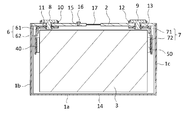
- FIG. 2 is a cross-sectional view of the secondary battery along the line II-II in FIG.
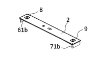
- FIG. 3A is a diagram showing a battery outer surface side of a sealing plate to which a positive electrode terminal, a negative electrode terminal, a first positive electrode current collector, and a first negative electrode current collector are attached.
- FIG. 3B is a diagram showing the inner surface side of the battery of the sealing plate to which the positive electrode terminal, the negative electrode terminal, the first positive electrode current collector, and the first negative electrode current collector are attached.
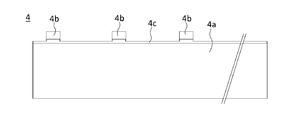
- FIG. 4 is a plan view of the positive electrode plate according to the embodiment.
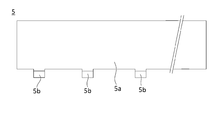
- FIG. 5 is a plan view of the negative electrode plate according to the embodiment.
- FIG. 6 is a plan view of the electrode body according to the embodiment.
- FIG. 7A is a plan view of the second positive electrode current collector according to the embodiment.
- FIG. 7B is a cross-sectional view of the second positive electrode current collector along the VIIB-VIIB line in FIG. 7B.
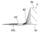
- FIG. 8 is a cross-sectional view showing a state in which the positive electrode tab group is connected to the second positive electrode current collector.
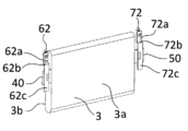
- FIG. 9 is a perspective view of an electrode body to which the second positive electrode current collector and the second negative electrode current collector are attached.
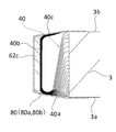
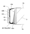
- FIG. 10 is a cross-sectional view of the vicinity of the connection portion between the second positive electrode current collector and the positive electrode tab group, and is a diagram showing a state in which the positive electrode tab group is bent and fixed.
- FIG. 11 is a perspective view of a group of electrode bodies including a plurality of electrode bodies.
- FIG. 12A is a diagram showing a state in which the first positive electrode current collector and the first negative electrode current collector are arranged between the second positive electrode current collector and the second negative electrode current collector.
- FIG. 12B is a diagram showing a state in which the distance between the second positive electrode current collector and the second negative electrode current collector is reduced.
- FIG. 12C is a diagram showing a state after connecting the first positive electrode current collector and the second positive electrode current collector and connecting the first negative electrode current collector and the second negative electrode current collector.
- FIG. 13 is a perspective view of the sealing plate and the electrode body group after connecting the first positive electrode current collector and the second positive electrode current collector and connecting the first negative electrode current collector and the second negative electrode current collector.
- FIG. 14 is a developed view of the electrode body holder according to the embodiment.
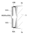
- FIG. 15 is a cross-sectional view of the vicinity of the connection portion between the second positive electrode current collector and the positive electrode tab group in another embodiment, and is a diagram showing a state in which the positive electrode tab group is bent and fixed.
- FIG. 16 is a cross-sectional view showing a state in which the positive electrode tab group is connected to the second positive electrode current collector in another embodiment.
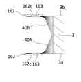
- FIG. 17 is a cross-sectional view of the vicinity of the connection portion between the second positive electrode current collector and the positive electrode tab group in another embodiment, and is a diagram showing a state in which the positive electrode tab group is bent and fixed.
- FIG. 18 is a diagram showing a state in which the second positive electrode current collector is connected to the first positive electrode current collector in another embodiment.
- the secondary battery 20 includes a battery case 100 including a bottomed square tubular outer body 1 having an opening and a sealing plate 2 for sealing the opening of the square outer body 1.
- the square exterior body 1 has a bottom portion 1a, a pair of first side walls 1b and 1c, and a pair of second side walls 1d and 1e.
- the pair of first side walls 1b and 1c are arranged so as to face each other, and the pair of second side walls 1d and 1e are arranged so as to face each other.
- the area of the pair of first side walls 1b and 1c is smaller than the area of the pair of second side walls 1d and 1e.
- the square exterior body 1 and the sealing plate 2 are preferably made of metal, more preferably aluminum or iron, respectively.
- the electrode body 3 including the positive electrode plate 4 and the negative electrode plate 5 is housed together with the electrolyte.
- the electrode body 3 according to the embodiment is a flat wound electrode body in which a band-shaped positive electrode plate 4 and a band-shaped negative electrode plate 5 are wound via a band-shaped separator.
- the positive electrode tab group 40 is provided at one end in the direction in which the winding shaft extends
- the negative electrode tab group 50 is provided at the other end in the direction in which the winding shaft extends. ..
- a positive electrode terminal 8 and a negative electrode terminal 9 are attached to the sealing plate 2.
- the positive electrode tab group 40 is electrically connected to the positive electrode terminal 8 via the positive electrode current collector 6.
- the positive electrode current collector 6 includes a first positive electrode current collector 61 and a second positive electrode current collector 62.
- the negative electrode tab group 50 is electrically connected to the negative electrode terminal 9 via the negative electrode current collector 7.
- the negative electrode current collector 7 includes a first negative electrode current collector 71 and a second negative electrode current collector 72.
- the positive electrode tab group 40 includes a plurality of positive electrode tabs 4b.
- the second positive electrode current collector 62 has a region arranged along the first side wall 1b of the square exterior body 1.
- the positive electrode tab group 40 is connected to the region of the second positive electrode current collector 62 arranged along the first side wall 1b in a bent state.
- the second positive electrode current collector 62 has a plate-shaped region arranged along the first side wall 1b of the square exterior body 1, and the positive electrode tab group 40 is provided on the surface of the plate-shaped region on the electrode body 3 side. It is connected.
- the inclination of the plate-shaped region with respect to the first side wall 1b is preferably smaller than ⁇ 30 °, more preferably smaller than ⁇ 15 °, and even more preferably smaller than ⁇ 10 °. It is more preferable that the plate-shaped region is substantially parallel to the first side wall 1b (for example, the inclination of the plate-shaped region with respect to the first side wall 1b is within ⁇ 5 °).
- the negative electrode tab group 50 includes a plurality of negative electrode tabs 5b.
- the second negative electrode current collector 72 has a region arranged along the first side wall 1c of the square exterior body 1.
- the negative electrode tab group 50 is connected to the region of the second negative electrode current collector 72 arranged along the first side wall 1c in a bent state.
- the second negative electrode current collector 72 has a plate-shaped region arranged along the first side wall 1c of the square exterior body 1, and the negative electrode tab group 50 is provided on the surface of the plate-shaped region on the electrode body 3 side. It is connected.
- the inclination of the plate-shaped region with respect to the first side wall 1c is preferably smaller than ⁇ 30 °, more preferably smaller than ⁇ 15 °, and even more preferably smaller than ⁇ 10 °. It is more preferable that the plate-shaped region is substantially parallel to the first side wall 1c (for example, the inclination of the plate-shaped region with respect to the first side wall 1b is within ⁇ 5 °).
- a resin external insulating member 10 is arranged between the sealing plate 2 and the positive electrode terminal 8.
- a resin internal insulating member 11 is arranged between the sealing plate 2 and the first positive electrode current collector 61.
- An external insulating member 12 made of resin is arranged between the sealing plate 2 and the negative electrode terminal 9.
- a resin internal insulating member 13 is arranged between the sealing plate 2 and the first negative electrode current collector 71.
- the electrode body 3 is arranged inside the electrode body holder 14 in which a resin insulating sheet is bent into a box shape or a bag shape.
- the sealing plate 2 is provided with an electrolytic solution injection hole 15, and the electrolytic solution injection hole 15 is sealed by a sealing member 16.
- the sealing plate 2 is provided with a gas discharge valve 17 that breaks when the pressure inside the battery case 100 exceeds a predetermined value and discharges the gas inside the battery case 100.
- the sealing plate 2 has a positive electrode terminal mounting hole near one end and a negative electrode terminal mounting hole near the other end.
- the external insulating member 10 is arranged on the outer surface side around the positive electrode terminal mounting hole of the sealing plate 2, and the internal insulating member 11 and the first positive electrode current collector 61 are arranged on the inner surface side around the positive electrode terminal mounting hole of the sealing plate 2.
- the positive electrode terminal 8 is inserted into the through hole of the external insulating member 10, the positive electrode terminal mounting hole of the sealing plate 2, the through hole of the internal insulating member 11, and the through hole of the first positive electrode current collector 61 from the outside of the battery. Insert and crimp the positive electrode terminal 8 onto the first positive electrode current collector 61. Further, it is more preferable to weld the crimped portion of the positive electrode terminal 8 to the first positive electrode current collector 61.
- the external insulating member 12 is arranged on the outer surface side around the negative electrode terminal mounting hole of the sealing plate 2, and the internal insulating member 13 and the first negative electrode current collector 71 are arranged on the inner surface side around the negative electrode terminal mounting hole of the sealing plate 2.
- the negative electrode terminal 9 is inserted into the through hole of the external insulating member 12, the negative electrode terminal mounting hole of the sealing plate 2, the through hole of the internal insulating member 13, and the through hole of the first negative electrode current collector 71 from the outside of the battery. Insert and crimp the negative electrode terminal 9 onto the first negative electrode current collector 71. Further, it is more preferable to weld the crimped portion of the negative electrode terminal 9 to the first negative electrode current collector 71.
- FIG. 3A and 3B are perspective views of the sealing plate 2 to which the positive electrode terminal 8, the first positive electrode current collector 61, the negative electrode terminal 9, and the first negative electrode current collector 71 are attached.
- FIG. 3A shows the outside side of the battery
- FIG. 3B shows the inside side of the battery.
- the first positive electrode current collector 61 has a first region 61a arranged along the sealing plate 2 and a second region 61b bent from the end of the first region 61a.
- the first region 61a is arranged between the sealing plate 2 and the electrode body 3.
- the second region 61b extends from the first region 61a toward the bottom 1a of the square exterior body 1.
- the second region 61b is arranged between the first side wall 1b of the square exterior body 1 and the electrode body 3.
- the first negative electrode current collector 71 has a first region 71a arranged along the sealing plate 2 and a second region 71b bent from the end of the first region 71a.
- the first region 71a is arranged between the sealing plate 2 and the electrode body 3.
- the second region 71b extends from the first region 71a toward the bottom portion 1a of the square exterior body 1.
- the second region 71b is arranged between the first side wall 1c of the square exterior body 1 and the electrode body 3.
- the cutout portion 61c is preferably arranged on the bottom portion 1a side of the square exterior body 1 from the internal side insulating member 11 in the second region 61b.
- the cutout portion 61c is preferably provided in the vicinity of the end portion on the first region 61a side in the second region 61b.
- the second region 71b of the first negative electrode current collector 71 is also preferably provided with cutouts 71c at both ends in the width direction.
- the cutout portion 61c preferably has a region not covered by the wall portion of the inner side insulating member 11.
- the positive electrode terminal 8 and the first positive electrode current collector 61 are preferably made of metal, more preferably made of aluminum.
- the negative electrode terminal 9 and the first negative electrode current collector 71 are preferably made of metal, more preferably copper.
- the negative electrode terminal 9 can include a region made of aluminum and a region made of copper. In this case, it is preferable to connect the region made of copper to the first negative electrode current collector 71 made of copper and expose the region made of aluminum to the outside of the battery.
- Lithium nickel cobalt manganese composite oxide as a positive electrode active material, polyvinylidene fluoride (PVdF) as a binder, carbon material as a conductive material, and N-methyl-2-pyrrolidone (NMP) as a dispersion medium are lithium nickel.
- the cobalt manganese composite oxide: PVdF: carbon material is kneaded so as to have a mass ratio of 97.5: 1: 1.5 to prepare a positive electrode active material layer slurry.
- PVdF polyvinylidene fluoride
- NMP N-methyl-2-pyrrolidone
- the positive electrode active material layer slurry and the positive electrode protective layer slurry prepared by the above method are applied to both sides of the aluminum foil as the positive electrode core by a die coater. At this time, the positive electrode active material layer slurry is applied to the center of the positive electrode core in the width direction. Further, the positive electrode protective layer slurry is applied to the end portion in the width direction of the region to which the positive electrode active material layer slurry is applied.
- the positive electrode core body coated with the positive electrode active material layer slurry and the positive electrode protective layer slurry is dried to remove NMP contained in the positive electrode active material layer slurry and the positive electrode protective layer slurry. As a result, the positive electrode active material layer and the positive electrode protective layer are formed. Then, the positive electrode active material layer is compressed to obtain a positive electrode original plate.
- This positive electrode original plate is cut into a predetermined shape to obtain a positive electrode plate 4.
- the positive electrode original plate can be cut by irradiating an energy ray such as a laser, a mold, or a cutter.
- FIG. 4 is a plan view of the positive electrode plate 4.
- the positive electrode plate 4 has regions in which positive electrode active material layers 4a are formed on both sides of the positive electrode core body.
- a plurality of positive electrode tabs 4b are provided at one end of the positive electrode plate 4 in the width direction.
- the positive electrode tab 4b is composed of an exposed portion of the positive electrode core.
- a positive electrode protective layer 4c having a lower conductivity than the positive electrode active material layer 4a is provided at the root portion of the positive electrode tab 4b.
- the positive electrode protective layer 4c may be an insulating layer made of resin, a layer containing ceramic and a resin binder, or the like. Further, the positive electrode protective layer 4c may contain a conductive material such as a carbon material. It is not necessary to provide the positive electrode protective layer 4c.
- the negative electrode active material layer slurry prepared by the above method is applied to both sides of a copper foil having a thickness of 8 ⁇ m as the negative electrode core by a die coater.
- the negative electrode core body coated with the negative electrode active material layer slurry is dried to remove the water contained in the negative electrode active material layer slurry. As a result, the negative electrode active material layer is formed. Then, the negative electrode active material layer is compressed to obtain a negative electrode original plate.
- This negative electrode original plate is cut into a predetermined shape to obtain a negative electrode plate 5.
- the negative electrode original plate can be cut by irradiating an energy ray such as a laser, a mold, or a cutter.
- FIG. 5 is a plan view of the negative electrode plate 5.
- the negative electrode plate 5 has a region in which the negative electrode active material layer 5a is formed on both sides of the negative electrode core body.
- a plurality of negative electrode tabs 5b are provided at one end of the negative electrode plate 5 in the width direction.
- the negative electrode tab 5b is composed of an exposed negative electrode core body.
- the strip-shaped positive electrode plate 4 and the strip-shaped negative electrode plate 5 produced by the above method are wound via a polyolefin strip-shaped separator to prepare a flat wound-shaped electrode body 3.
- the electrode body 3 has a flat region in the center and curved portions at both ends of the flat region.
- One outer surface of the flat region is the first main surface 3a, and the other outer surface of the flat region is the second main surface 3b.
- FIG. 6 is a plan view of the electrode body 3.
- a positive electrode tab group 40 in which a plurality of positive electrode tabs 4b are laminated is provided at one end of the electrode body 3 in the direction in which the winding axis extends.
- a negative electrode tab group 50 in which a plurality of negative electrode tabs 5b are laminated is provided at the other end of the electrode body 3 in the direction in which the winding axis extends.
- the center of the tab group 50 is arranged so as to be offset from the winding axis to one side (upper side in FIG. 6).
- the shape of the positive electrode tab 4b and / or the negative electrode tab 5b in a plan view can be formed so that the width gradually increases from the tip to the root. With such a configuration, even if an impact or vibration is applied to the secondary battery 20, the positive electrode tab 4b and / or the negative electrode tab 5b is not easily damaged. Further, it is more effective to make the corner portion of the root portion R-shaped.
- the positive electrode protective layer 4c at the root portion of the positive electrode tab 4b as described above, damage to the positive electrode tab 4b can be suppressed.
- the negative electrode active material layer 5a at the root portion of the negative electrode tab 5b damage to the negative electrode tab 5b can be suppressed.
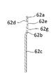
- FIG. 7A is a plan view of the second positive electrode current collector 62.
- FIG. 7B is a cross-sectional view taken along the line VIIB-VIIB in FIG. 7A.
- the second positive electrode current collector 62 has a second region connecting portion 62a, an inclined portion 62b, and a tab connecting portion 62c.
- the second region connecting portion 62a is connected to the second region 61b of the first positive electrode current collector 61.
- the positive electrode tab group 40 is connected to the tab connection portion 62c.
- the inclined portion 62b is arranged so as to be inclined with respect to each of the second region connecting portion 62a and the tab connecting portion 62c, and connects the second region connecting portion 62a and the tab connecting portion 62c.
- the inclined portion 62b forms a step between the second region connecting portion 62a and the tab connecting portion 62c.
- the angle of the inclined portion 62b with respect to the second region connecting portion 62a and the angle of the inclined portion 62b with respect to the tab connecting portion 62c are not particularly limited.
- the shape of the second positive electrode current collector 62 is not limited. It is also possible to make the second positive electrode current collector 62 into a flat plate shape.
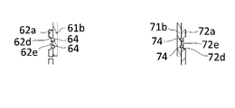
- a recess 62d is provided in the second region connection portion 62a.
- the portion provided with the recess 62d is thinner than the periphery thereof.
- a through hole 62e is provided inside the recess 62d. Inside the recess 62d, the second region 61b and the second region connecting portion 62a are joined.
- a fuse portion 62f is provided in the second region connection portion 62a.
- the fuse portion 62f is a portion that blows when an excessive current flows through the secondary battery 20.
- the fuse portion 62f is a portion whose cross-sectional area is reduced by forming a fuse hole 62g in the second region connecting portion 62a.
- the fuse portion 62f is preferably provided between the position where the second region 61b is joined and the position where the positive electrode tab group 40 is joined in the second positive electrode current collector 62.
- the fuse portion 62f may be a portion having a small cross-sectional area, and may be a portion provided with a notch or a thin wall portion.
- the shape of the second negative electrode current collector 72 can be the same as that of the second positive electrode current collector 62.
- the second positive electrode current collector 62 is preferably made of metal, more preferably made of aluminum.
- the second negative electrode current collector 72 is preferably made of metal, more preferably copper, nickel, or iron.
- the positive electrode tab group 40 is arranged on the tab connection portion 62c of the second positive electrode current collector 62, and the tab connection portion 62c and the positive electrode tab group 40 are joined to form the joint portion 63.
- ultrasonic welding ultrasonic bonding
- resistance welding resistance welding
- the tab connection portion 72c of the second negative electrode current collector 72 and the negative electrode tab group 50 can also be joined in the same manner.
- the joint portion 63 is located on the root side (right side in FIG. 8) of the positive electrode tab group 40 in the width direction of the tab connection portion 62c (left-right direction in FIG. 8). It is preferably arranged eccentrically. With such a configuration, when the positive electrode tab group 40 is bent, a curved shape can be more reliably formed in the vicinity of the root of the positive electrode tab group 40. As a result, damage to the positive electrode tab group 40 can be suppressed. Further, even if the positive electrode tab 4b is misaligned, the positive electrode tab group 40 and the tab connection portion 62c can be stably joined.
- the tip of the positive electrode tab group 40 is tab-connected to the positive electrode tab group 40 in a state of protruding outward (left side in FIG. 8) from the tab connection portion 62c of the second positive electrode current collector 62. It is preferable to join the portions 62c. As a result, the positive electrode tab group 40 and the tab connection portion 62c can be joined more stably.
- FIG. 9 is a perspective view of the electrode body 3 to which the second positive electrode current collector 62 and the second negative electrode current collector 72 are attached.
- the lower end of the second positive electrode current collector 62 (the end of the square exterior body 1 on the bottom 1a side) is the lower end of the positive electrode tab group 40 (the end of the square exterior 1 on the bottom 1a side). ) Is preferably located below.
- the positive electrode tab group 40 is in a bent state.
- the tab connection portion 62c of the second positive electrode current collector 62 which is arranged substantially parallel to the first main surface 3a and the second main surface 3b of the electrode body 3, is provided with the positive electrode tab group 40.
- the orientation is substantially perpendicular to the winding axis (for example, the inclination of the tab connection portion 62c with respect to the winding axis is smaller than ⁇ 15 °).
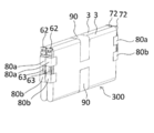
- the tape 80 as a fixing means is attached so as to straddle the first main surface 3a-tab connection portion 62c of the electrode body 3 and the second main surface 3b of the electrode body 3.
- the positive electrode tab group 40 can be maintained in a curved state more stably. Further, the curved positive electrode tab group 40 can be made elastic, and when the second positive electrode current collector 62 is pressed toward the electrode body 3, the second positive electrode current collector 62 moves in a direction approaching the electrode body 3. be able to. When the positive electrode tab group 40 is bent, the second positive electrode current collector 62 itself is not bent.
- the positive electrode tab group 40 has a contact region 40b that abuts on the tab connection portion 62c, a root region 40a and a contact region 40b that are arranged on the root side of the positive electrode tab group 40 with respect to the contact region 40b. It has a tip region 40c arranged on the tip side of the positive electrode tab group 40.
- the negative electrode tab group 50 is also fixed in a bent state in the same manner as the positive electrode tab group 40.
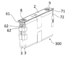
- Electrode body group A plurality of electrode bodies 3 in which the positive electrode tab group 40 and the negative electrode tab group 50 are each bent are laminated and fixed together with an electrode body fixing means 90 such as a tape to form an electrode body group 300.
- FIG. 11 is a perspective view of the electrode body group 300.
- Each positive electrode tab group 40 is arranged on the same side, and each negative electrode tab group 50 is arranged on the same side. Further, in each electrode body 3, the positive electrode tab group 40 is bent in the same direction. In each electrode body 3, the negative electrode tab group 50 is bent in the same direction.
- the electrode body group 300 according to the embodiment includes two electrode bodies 3. The number of electrode bodies 3 included in the electrode body group 300 is not limited to two.
- the first tape 80a and the second tape 80b are included as the tape 80 as a fixing means to be attached across the first main surface 3a of the electrode body 3-tab connection portion 62c-the second main surface 3b of the electrode body 3. Is preferable.
- the first tape 80a is attached above the joint portion 63 of the tab connection portion 62c and the positive electrode tab group 40, and the tab connection portion 62c and the tab connection portion 62c are attached. It is preferable to attach the second tape 80b below the joint portion 63 of the positive electrode tab group 40. With such a configuration, the curved state of the positive electrode tab group 40 can be stably maintained.
- the tab connection portion 72c of the second negative electrode current collector 72 is included as the tape 80 as a fixing means to be attached across the first main surface 3a of the electrode body 3-tab connection portion 62c-the second main surface 3b of the electrode body 3.
- the tab connection portion 62c of the second positive electrode current collector 72 is attached above the joint portion 63 of the tab connection portion 62c and the
- the upper end of the first tape 80a arranged on the upper side is arranged above the upper end of the positive electrode tab group 40, and the lower end of the second tape 80b arranged on the lower side is the positive electrode tab group 40. It is preferably arranged below the lower end. With such a configuration, the curved shape of the positive electrode tab group 40 can be maintained more reliably.
- the second positive electrode current collectors 62 attached to the electrode bodies 3 are arranged at intervals and on the second region 61b of the first positive electrode current collector 61. It is connected to the. The same applies to each second negative electrode current collector 72.
- the joint portion 63 between the positive electrode tab group 40 and the tab connection portion 62c is arranged between the lower end of the first tape 80a and the upper end of the second tape 80b.
- the upper and lower tapes are divided into two tapes, the first tape 80a and the second tape 80b, but one tape can also be used.
- the upper end of one tape is arranged above the upper end of the positive electrode tab group 40 and the lower end of one tape is arranged below the lower end of the positive electrode tab group 40.
- the tape 80 may cover the portion of the tab connection portion 62c where the joint portion 63 is formed. The same configuration can be applied to the second negative electrode current collector 72 and the negative electrode tab group 50 side.
- the second region 61b of the first positive electrode current collector 61 is arranged inside the second region connection portion 62a of the second positive electrode current collector 62, and the second region 71b of the first negative electrode current collector 71 is the second negative electrode current collector. It is arranged inside the second region connection portion 72a of the electric body 72. Then, the second region 61b of the first positive electrode current collector 61 and the second region connection portion 62a of the second positive electrode current collector 62 are connected. Further, the second region 71b of the first negative electrode current collector 71 is joined to the second region connection portion 72a of the second negative electrode current collector 72.
- ultrasonic welding ultrasonic bonding
- resistance welding welding by irradiation with a high energy ray such as a laser, or the like
- welding by irradiating a high energy ray such as a laser.
- 12A to 12C show a second region 61b of the first positive electrode current collector 61, a second region 71b of the first negative electrode current collector 71, and a second region connection portion 62a of the second positive electrode current collector 62 at each stage.
- And is a cross-sectional view taken along the winding axis of the electrode body 3 of the second region connecting portion 72a of the second negative electrode current collector 72.
- the second of the first positive electrode current collector 61 is between the second region connection portion 62a of the second positive electrode current collector 62 and the second region connection portion 72a of the second negative electrode current collector 72.
- the region 61b and the second region 71b of the first negative electrode current collector 71 are arranged.
- the distance D1 between the inner surface of the second region connecting portion 62a and the inner surface of the second region connecting portion 72a is preferably larger than the distance D2 between the outer surface of the second region 61b and the outer surface of the second region 71b.
- D1 is preferably 0.1 to 5 mm larger than D2, and more preferably 0.2 to 3 mm larger.
- the second region connection portion 62a and / or the second region connection portion 72a is displaced inward so that the distance between the second region connection portion 62a and the second region connection portion 72a becomes small.
- the distance D1 between the inner surface of the second region connecting portion 62a and the inner surface of the second region connecting portion 72a is changed to D1'.
- the difference between D2 and D1' is preferably 0 to 0.2 mm.
- a high energy ray such as a laser is irradiated to each of the second region connecting portion 62a and the second region connecting portion 72a.
- a high energy ray such as a laser is irradiated to each of the second region connecting portion 62a and the second region connecting portion 72a.
- the second region 61b of the first positive electrode current collector 61 and the second region connection portion 62a of the second positive electrode current collector 62 are joined by welding, and the second region 71b and the first negative electrode current collector 71 of the first negative electrode current collector 71 are joined.
- the second region connection portion 72a of the negative electrode current collector 72 is joined by welding.
- a joint portion 64 which is a welded portion between the second region 61b and the second region connection portion 62a, is formed in the recess 62d.
- a joint portion 74 which is a welded portion between the second region 71b and the second region connection portion 72a, is formed in the recess 72d.
- the first positive electrode current collector 61 and the second positive electrode current collector 62, the first negative electrode current collector 71 and the second negative electrode current collector 72, Can be welded more stably. Therefore, the highly reliable joint portion 64 and the joint portion 74 can be formed.
- the portion where the recess 62d and the recess 72d are formed is a portion thinner than the periphery thereof.
- a higher quality joint portion can be formed more stably. Therefore, it becomes a more reliable secondary battery.
- the through hole 62e to measure the presence or absence of a gap or the size of the gap between the second region 61b and the second region connecting portion 62a, the second region 61b and the second region connecting portion can be more stably connected.
- 62a can be joined by welding. The same applies to the through hole 72e.
- FIG. 13 is a perspective view showing a state after connecting the first positive electrode current collector 61 and the second positive electrode current collector 62, and the first negative electrode current collector 71 and the second negative electrode current collector 72, respectively.
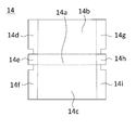
- FIG. 14 is a developed view of the electrode body holder 14.
- the insulating sheet constituting the electrode body holder 14 is bent at the portion indicated by the broken line to form a box-shaped electrode body holder 14.
- the electrode body holder 14 includes a holder bottom 14a, a holder first main surface 14b, a holder second main surface 14c, a holder first side surface 14d, a holder second side surface 14e, a holder third side surface 14f, a holder fourth side surface 14g, and a holder first. It has 5 side surfaces 14h and a holder 6th side surface 14i.
- the electrode body holder 14 When the electrode body holder 14 has a box shape, it has a region where the holder first side surface 14d, the holder second side surface 14e, and the holder third side surface 14f overlap, and the holder fourth side surface 14g, the holder fifth side surface 14h, and the holder The sixth side surface 14i has an overlapping region.
- the electrode body group 300 With the electrode body group 300 arranged in the box-shaped electrode body holder 14, the electrode body group 300 is inserted into the square exterior body 1. Then, the sealing plate 2 is joined to the square exterior body 1, and the opening of the square exterior body 1 is sealed by the sealing plate 2. The electrolytic solution is injected from the electrolytic solution injection hole 15 provided in the sealing plate 2, and the electrolytic solution injection hole 15 is sealed by the sealing member 16. As a result, the secondary battery 20 is used.
- the positive electrode current collector 6 includes the first positive electrode current collector 61 and the second positive electrode current collector 62.
- the positive electrode tab group 40 when the positive electrode tab group 40 is bent, the positive electrode tab group 40 can be bent without bending the positive electrode current collector 6, and the volume energy density can be more stably obtained by a simpler method. It can be a high secondary battery. It is more effective when the number of electrode bodies 3 housed in the battery case 100 is two or more. According to the present disclosure, the degree of freedom regarding the number of electrode bodies 3 housed in the battery case 100 is improved.
- the present disclosure even when the number of electrode bodies 3 housed in the battery case 100 is larger than two, a highly reliable secondary battery can be stably provided without making the positive electrode current collector 6 a complicated shape. It will be possible to manufacture.
- the present disclosure is particularly effective when the number of electrode bodies 3 housed in the battery case 100 is more than two and an odd number.
- the tab connection portion 62c of the second positive electrode current collector 62 is arranged closer to the first side wall 1b of the square exterior body 1 than the second region connection portion 62a of the second positive electrode current collector 62.
- the positive electrode tab group 40 is preferably eccentric to the sealing plate 2 side. As a result, the conductive path from the positive electrode tab group 40 to the positive electrode terminal 8 can be shortened, and the secondary battery 20 has a small internal resistance.
- the negative electrode tab group 50 is preferably eccentric to the sealing plate 2 side. As a result, the conductive path from the negative electrode tab group 50 to the negative electrode terminal 9 can be shortened, and the secondary battery 20 has a small internal resistance.
- the electrode body holder 14 It is preferable to arrange another insulating member (not shown). Further, an electrode body holder is located between the region where the second region 71b of the first negative electrode current collector 71 and the second region connection portion 72a of the second negative electrode current collector 72 overlap and the first side wall 1c of the square exterior body 1. It is preferable to arrange an insulating member (not shown) different from 14. With such a configuration, even when an impact or vibration is applied to the secondary battery 20, it is possible to prevent damage to the joints between the members, the positive electrode tab group 40, or the negative electrode tab group 50.
- FIG. 15 is a cross-sectional view of the vicinity of the tab connection portion 62c of the second positive electrode current collector 62 and the joint portion 63 of the positive electrode tab group 40 in another embodiment, showing a state in which the positive electrode tab group 40 is bent and fixed. It is a figure which shows.
- the portion where the joint portion 63 is formed in the tab connection portion 62c of the second positive electrode current collector 62 can be covered with the tape 80. Even if burrs and metal powder generated when the joint portion 63 is formed are present in the portion where the joint portion 63 is formed in the tab connection portion 62c of the second positive electrode current collector 62, the tape 80 causes burrs and burrs. The movement of metal powder can be suppressed.
- the portion where the joint portion 63 is formed in the positive electrode tab group 40 can be covered with the tape 81. Even if burrs and metal powder generated when the joint portion 63 is formed are present in the portion of the positive electrode tab group 40 where the joint portion 63 is formed, the tape 81 suppresses the movement of burrs and metal powder. it can.
- the tape 81 is preferably attached before the positive electrode tab group 40 is bent.
- An adhesive material is applied or an adhesive material is applied to a portion where the joint portion 63 is formed in the tab connection portion 62c of the second positive electrode current collector 62 and / or a portion where the joint portion 63 is formed in the positive electrode tab group 40.
- the portion where the joint portion 63 is formed in the tab connection portion 62c of the second positive electrode current collector 62 and / or the portion where the joint portion 63 is formed in the positive electrode tab group 40 can be covered with the heat welding resin. ..
- the tab connection portion 72c of the second negative electrode current collector 72 and the negative electrode tab group 50 can have the same configuration.
- one second positive electrode current collector 62 and one second negative electrode current collector 72 are attached to one electrode body 3.
- a plurality of second positive electrode current collectors and / or a plurality of second negative electrode current collectors can be attached to one electrode body 3.
- Another embodiment in which a plurality of second positive electrode current collectors are attached to one electrode body 3 will be described below.
- a plurality of second negative electrode current collectors can be attached to one electrode body 3 by the same method.
- the parts common to the secondary battery 20 of the above-described embodiment will not be described.
- the positive electrode tab group 40 is divided into two, and one positive electrode tab group 40A and the other positive electrode tab group 40B, which are divided into two, have tabs of the second positive electrode current collector 162.
- the connection portion 162c is connected by welding to form the joint portion 163. It is preferable that one positive electrode tab group 40A is collected on the first main surface 3a side and the other positive electrode tab group 40B is collected on the second main surface 3b side.
- the second positive electrode current collector 162 can have the same configuration as the second positive electrode current collector 62 according to the above-described embodiment.
- the positive electrode tab group 40A bundled on the first main surface 3a side is bent toward the center side in the thickness direction of the electrode body 3, and the positive electrode tab group bundled on the second main surface 3b side.
- the 40B is fixed by the tape 80 as a fixing means in a state where the 40B is bent toward the center side in the thickness direction of the electrode body 3.
- the second positive electrode current collector 162 connected to the positive electrode tab group 40A of one electrode body 3 and the second positive electrode current collector 162 connected to the positive electrode tab group 40B are combined with the first positive electrode collector. It is connected to the electric body 61 by welding.
- the second positive electrode current collector 162 has a second region connecting portion 162a, an inclined portion 162b, and a tab connecting portion 162c.
- the second region connecting portion 162a is connected to the second region 61b of the first positive electrode current collector 61.
- the configuration in the other embodiment is particularly effective when the thickness of one of the electrode bodies 3 is increased.
- the electrode body is a wound type electrode body in which the positive electrode plate and the negative electrode plate are wound by the separator, but the present invention is not limited to this.
- a laminated electrode body including a plurality of positive electrode plates and a plurality of negative electrode plates can also be used.
- an example of producing a wound electrode body by winding a positive electrode plate on which a plurality of positive electrode tabs are formed and a negative electrode plate on which a plurality of negative electrode tabs are formed has been shown. Not limited. By cutting the exposed portion of the positive electrode core or the exposed portion of the negative electrode core that is wound in the wound electrode body, a positive electrode tab group or a negative electrode tab group can be formed.
- the positive electrode current collector 6 and the negative electrode current collector 7 are each composed of two parts, but the positive electrode current collector 6 and the negative electrode current collector 7 are each composed of one component. You may.
- Known materials can be used for the positive electrode plate, the negative electrode plate, the separator, the electrolyte, and the like.
- the above-mentioned aluminum includes aluminum and an aluminum alloy mainly composed of aluminum.
- the above-mentioned copper shall include copper and a copper alloy mainly composed of copper.
- the above-mentioned iron shall contain an iron alloy mainly composed of iron.
- the above-mentioned nickel includes a nickel alloy mainly composed of nickel.
- the tape preferably has a base material and an adhesive layer formed on the base material.
- the base material is preferably composed of polyethylene, polypropylene, polyester, nylon, vinyl chloride, Teflon (registered trademark), polyimide, Kapton (registered trademark), polyphenylene sulfide, polyethylene naphthalate and the like.
- the material of the adhesive layer is preferably composed of an acrylic adhesive, a silicon adhesive, a rubber adhesive, or the like. However, it is not limited to these materials.
- the adhesive layer preferably has adhesiveness at room temperature.
- the fixing means is a tape
- the present invention is not limited to this.
- a resin frame, a metal frame, a ceramic frame, a clip-shaped member, or the like can be considered.
- tape is more preferable.
- a pressure-sensitive current cutoff mechanism can be provided in the conductive path between the positive electrode tab group and the positive electrode terminal, or in the conductive path between the negative electrode tab group and the negative electrode terminal. This current cutoff mechanism operates when the pressure inside the battery case exceeds a predetermined value, and cuts the conductive path between the positive electrode tab group and the positive electrode terminal or the conductive path between the negative electrode tab group and the negative electrode terminal. , A mechanism that cuts off the flow of electric current.
Landscapes
- Chemical & Material Sciences (AREA)
- Chemical Kinetics & Catalysis (AREA)
- Electrochemistry (AREA)
- General Chemical & Material Sciences (AREA)
- Engineering & Computer Science (AREA)
- Manufacturing & Machinery (AREA)
- Connection Of Batteries Or Terminals (AREA)
- Sealing Battery Cases Or Jackets (AREA)
Abstract
Description
正極板と負極板を含む電極体と、
開口を有し、前記電極体を収容する角形外装体と、
前記開口を封口する封口板と、
前記封口板に取り付けられた端子と、を備えた二次電池であって、
前記電極体は、一方の端部に正極タブ群を有し、他方の端部に負極タブ群を有し、
前記電極体は、互いに対向する向きに配置された第1主面と第2主面を有し、
前記角形外装体は、底部、互いに対向する向きに配置された一対の第1側壁、及び互いに対向する向きに配置された一対の第2側壁を有し、
前記正極タブ群は一方の前記第1側壁側に配置され、
前記負極タブ群は他方の前記第1側壁側に配置され、
前記正極タブ群又は前記負極タブ群と、前記端子とは、集電体により電気的に接続され、
前記正極タブ群又は前記負極タブ群は折り曲げられた状態で前記集電体に接続され、
前記第1主面―前記集電体―前記第2主面に跨って固定手段が取り付けられている。
前記固定手段の前記底部側の端部は、前記正極タブ群又は前記負極タブ群の前記底部側の端部よりも前記底部側に位置する構成とすることができる。
正極板と負極板を含む電極体と、
開口を有し、前記電極体を収容する角形外装体と、
前記開口を封口する封口板と、
前記封口板に取り付けられた端子と、を備え、
前記電極体は、一方の端部に正極タブ群を有し、他方の端部に負極タブ群を有し、
前記電極体は、互いに対向する向きに配置された第1主面と第2主面を有し、
前記角形外装体は、底部、互いに対向する向きに配置された一対の第1側壁、及び互いに対向する向きに配置された一対の第2側壁を有し、
前記正極タブ群又は前記負極タブ群と、前記端子とは、集電体により電気的に接続された、二次電池の製造方法であって、
前記正極タブ群又は前記負極タブ群と前記集電体を接続する工程と、
前記正極タブ群又は前記負極タブ群を折り曲げると共に、前記正極タブ群又は前記負極タブ群に接続された前記集電体の向きを変える工程と、
前記第1主面―前記集電体―前記第2主面に跨って固定手段を取り付けられることにより、前記正極タブ群又は前記負極タブ群を折り曲げられた状態で固定する工程を有する。
前記第2集電体に前記正極タブ群又は前記負極タブ群が接続され、
前記正極タブ群又は前記負極タブ群が接続されて前記固定手段が取り付けられた前記第2集電体を、前記封口板に取り付けられた前記第1集電体に接続する工程を有することができる。
封口板2は、一方の端部近傍に正極端子取り付け孔を有し、他方の端部近傍に負極端子取り付け孔を有する。封口板2の正極端子取り付け孔の周囲の外面側に外部側絶縁部材10を配置し、封口板2の正極端子取り付け孔の周囲の内面側に内部側絶縁部材11及び第1正極集電体61を配置する。そして、電池外部側から正極端子8を、外部側絶縁部材10の貫通孔、封口板2の正極端子取り付け孔、内部側絶縁部材11の貫通孔、及び第1正極集電体61の貫通孔に挿入し、正極端子8を第1正極集電体61上にカシメる。更に、正極端子8においてカシメられた部分を、第1正極集電体61に溶接することがより好ましい。
まず、正極板の製造方法を説明する。
正極活物質としてのリチウムニッケルコバルトマンガン複合酸化物、結着材としてのポリフッ化ビニリデン(PVdF)、導電材としての炭素材料、及び分散媒としてのN-メチル-2-ピロリドン(NMP)をリチウムニッケルコバルトマンガン複合酸化物:PVdF:炭素材料の質量比が97.5:1:1.5となるように混練し、正極活物質層スラリーを作製する。
アルミナ粉末、導電材としての炭素材料、結着材としてのポリフッ化ビニリデン(PVdF)と分散媒としてのN-メチル-2-ピロリドン(NMP)を、アルミナ粉末:炭素材料:PVdFの質量比が83:3:14となるように混練し、保護層スラリーを作製する。
正極芯体としてアルミニウム箔の両面に、上述の方法で作製した正極活物質層スラリー及び正極保護層スラリーをダイコータにより塗布する。このとき、正極芯体の幅方向の中央に正極活物質層スラリーが塗布される。また、正極活物質層スラリーが塗布される領域の幅方向の端部に正極保護層スラリーが塗布される。
次に、負極板の製造方法を説明する。
負極活物質としての黒鉛、結着材としてのスチレンブタジエンゴム(SBR)及びカルボキシメチルセルロース(CMC)、及び分散媒としての水を、黒鉛:SBR:CMCの質量比が98:1:1となるように混練し、負極活物質層スラリーを作製する。
負極芯体としての厚さ8μmの銅箔の両面に、上述の方法で作製した負極活物質層スラリーをダイコータにより塗布する。
上述の方法で作製した帯状の正極板4及び帯状の負極板5を、ポリオレフィン製の帯状のセパレータを介して巻回し、扁平状の巻回型の電極体3を作製する。電極体3は、中央に扁平状の領域を有し、扁平状の領域の両端に湾曲部を有する。平坦状の領域の一方の外面が第1主面3aであり、平坦状の領域の他方の外面が第2主面3bである。
図7Aは、第2正極集電体62の平面図である。図7Bは、図7AにおけるVIIB-VIIB線に沿った断面図である。第2正極集電体62は、第2領域接続部62a、傾斜部62b、タブ接続部62cを有する。第2領域接続部62aが第1正極集電体61の第2領域61bに接続される。タブ接続部62cに正極タブ群40が接続される。傾斜部62bは、第2領域接続部62a及びタブ接続部62cのそれぞれに対して傾斜して配置され、第2領域接続部62aとタブ接続部62cを繋ぐ。傾斜部62bにより第2領域接続部62aとタブ接続部62cの間に段差が形成される。なお、第2領域接続部62aに対する傾斜部62bの角度、及びタブ接続部62cに対する傾斜部62bの角度は特に限定されない。なお、第2正極集電体62の形状は限定されない。第2正極集電体62を平坦な板状とすることも可能である。
図8に示すように、第2正極集電体62のタブ接続部62c上に正極タブ群40を配置し、タブ接続部62cと正極タブ群40を接合し接合部63を形成する。接合には、超音波溶接(超音波接合)、抵抗溶接、レーザー等の高エネルギー線の照射による溶接等を用いることができる。第2負極集電体72のタブ接続部72cと負極タブ群50も同様の方法で接合できる。
図10に示すように正極タブ群40を折り曲げた状態とする。図9に示すように電極体3の第1主面3a及び第2主面3bに対して略平行に配置されていた第2正極集電体62のタブ接続部62cを、正極タブ群40を折り曲げることにより、電極体3の巻回軸に対して略垂直な向き(例えば、巻回軸に対するタブ接続部62cの傾きが±15°より小さい)とされた状態とする。そして、電極体3の第1主面3a-タブ接続部62c-電極体3の第2主面3bに跨るように固定手段としてのテープ80を貼り付ける。このような構成であると、より安定的に正極タブ群40が湾曲した状態を維持できる。また、湾曲した正極タブ群40に弾性を持たせることができ、第2正極集電体62を電極体3側に押圧した場合、第2正極集電体62が電極体3に近づく方向に動くことができる。なお、正極タブ群40を折り曲げる際、第2正極集電体62自体は折り曲げられない。
正極タブ群40及び負極タブ群50がそれぞれ折り曲げられた状態の複数の電極体3を積層し、テープ等の電極体固定手段90で纏めて固定し、電極体群300とする。図11は電極体群300の斜視図である。各正極タブ群40は同じ側に配置され、各負極タブ群50は同じ側に配置される。また、各電極体3において、正極タブ群40はそれぞれ同じ方向に折り曲げられている。各電極体3において、負極タブ群50はそれぞれ同じ方向に折り曲げられている。実施形態に係る電極体群300は、2つの電極体3を含む。なお、電極体群300が含む電極体3の数は2つに限定されない。
第1正極集電体61の第2領域61bを第2正極集電体62の第2領域接続部62aの内側に配置し、第1負極集電体71の第2領域71bを第2負極集電体72の第2領域接続部72aの内側に配置する。そして、第1正極集電体61の第2領域61bと第2正極集電体62の第2領域接続部62aを接続する。また、第1負極集電体71の第2領域71bを第2負極集電体72の第2領域接続部72aに接合する。接合方法としては、超音波溶接(超音波接合)、抵抗溶接、レーザー等の高エネルギー線の照射による溶接等を用いることができる。特にレーザー等の高エネルギー線の照射による溶接を用いることが好ましい。
図14は、電極体ホルダー14の展開図である。図14において破線の部分で電極体ホルダー14を構成する絶縁シートを折り曲げることにより箱状の電極体ホルダー14とする。電極体ホルダー14は、ホルダー底部14a、ホルダー第1主面14b、ホルダー第2主面14c、ホルダー第1側面14d、ホルダー第2側面14e、ホルダー第3側面14f、ホルダー第4側面14g、ホルダー第5側面14h、ホルダー第6側面14iを有する。
実施形態に係る二次電池20においては、正極集電体6が第1正極集電体61と第2正極集電体62を含む構成となっており。このような構成であると、正極タブ群40を折り曲げる際、正極集電体6を折り曲げることなく、正極タブ群40を折り曲げることができ、より簡単な方法で、より安定的に体積エネルギー密度が高い二次電池とすることができる。なお、電池ケース100に収容される電極体3の数が2個以上の場合、より効果的である。本開示によると、電池ケース100に収容される電極体3の個数についての自由度が向上する。本開示によると、電池ケース100に収容される電極体3の数が2個より多い場合でも、正極集電体6を複雑な形状とすることなく、信頼性の高い二次電池を安定的に製造できるようになる。本開示は、電池ケース100に収容される電極体3の個数が2個より多く、奇数個の場合特に効果的である。
上述の実施形態においては、電極体が正極板と負極板がセパレータを介して巻回された巻回型の電極体である例を示したが、これに限定されない。複数の正極板と複数の負極板を含む積層型の電極体とすることもできる。
100 電池ケース
1 角形外装体
1a 底部
1b,1c 第1側壁
1d,1e 第2側壁
2 封口板
3 電極体
3a 第1主面
3b 第2主面
300 電極体群
4 正極板
4a 正極活物質層
4b 正極タブ
4c 正極保護層
40 正極タブ群
40a 根本領域
40b 当接領域
40c 先端領域
5 負極板
5a 負極活物質層
5b 負極タブ
50 負極タブ群
6 正極集電体
61 第1正極集電体
61a 第1領域
61b 第2領域
61c 切り欠き部
62 第2正極集電体
62a 第2領域接続部
62b 傾斜部
62c タブ接続部
62d 凹部
62e 貫通孔
62f ヒューズ部
62g ヒューズ孔
63,64 接合部
7 負極集電体
71 第1負極集電体
71a 第1領域
71b 第2領域
71c 切り欠き部
72 第2負極集電体
72a 第2領域接続部
72b 傾斜部
72c タブ接続部
72d 凹部
72e 貫通孔
74 接合部
8 正極端子
9 負極端子
10,12 外部側絶縁部材
11,13 内部側絶縁部材
14 電極体ホルダー
14a ホルダー底部
14b ホルダー第1主面
14c ホルダー第2主面
14d ホルダー第1側面
14e ホルダー第2側面
14f ホルダー第3側面
14g ホルダー第4側面
14h ホルダー第5側面
14i ホルダー第6側面
15 電解液注液孔
16 封止部材
17 ガス排出弁
80 テープ
80a 第1テープ
80b 第2テープ
81 テープ
90 電極体固定手段
40A,40B 正極タブ群
162 第2正極集電体
162a 第2領域接続部
162b 傾斜部
162c タブ接続部
163 接合部
Claims (11)
- 正極板と負極板を含む電極体と、
開口を有し、前記電極体を収容する角形外装体と、
前記開口を封口する封口板と、
前記封口板に取り付けられた端子と、を備えた二次電池であって、
前記電極体は、一方の端部に正極タブ群を有し、他方の端部に負極タブ群を有し、
前記電極体は、互いに対向する向きに配置された第1主面と第2主面を有し、
前記角形外装体は、底部、互いに対向する向きに配置された一対の第1側壁、及び互いに対向する向きに配置された一対の第2側壁を有し、
前記正極タブ群は一方の前記第1側壁側に配置され、
前記負極タブ群は他方の前記第1側壁側に配置され、
前記正極タブ群又は前記負極タブ群と、前記端子とは、集電体により電気的に接続され、
前記正極タブ群又は前記負極タブ群は折り曲げられた状態で前記集電体に接続され、
前記第1主面―前記集電体―前記第2主面に跨って固定手段が取り付けられた二次電池。 - 前記集電体の幅方向において、前記集電体と前記正極タブ群又は前記負極タブ群の接合部は、前記正極タブ群又は前記負極タブ群の根本側に偏心している請求項1に記載の二次電池。
- 前記正極タブ群又は前記負極タブ群は、前記集電体に当接された当接領域と、前記当接領域よりも前記正極タブ群又は前記負極タブ群の根本側に配置された根本領域と、前記当接領域よりも前記正極タブ群又は前記負極タブ群の先端側に配置された先端領域と、を有する請求項1又は2に記載の二次電池。
- 前記固定手段が前記先端領域に接する請求項3に記載の二次電池。
- 前記固定手段はテープである請求項1~4のいずれかに記載の二次電池。
- 前記固定手段の前記封口板側の端部は、前記正極タブ群又は前記負極タブ群の前記封口板側の端部よりも前記封口板側に位置し、
前記固定手段の前記底部側の端部は、前記正極タブ群又は前記負極タブ群の前記底部側の端部よりも前記底部側に位置する請求項1~5のいずれかに記載の二次電池。 - 前記集電体の前記底部側の端部は、前記正極タブ群又は前記負極タブ群の前記底部側の端部よりも前記底部側に位置する請求項1~6のいずれかに記載の二次電池。
- 正極板と負極板を含む電極体と、
開口を有し、前記電極体を収容する角形外装体と、
前記開口を封口する封口板と、
前記封口板に取り付けられた端子と、を備え、
前記電極体は、一方の端部に正極タブ群を有し、他方の端部に負極タブ群を有し、
前記電極体は、互いに対向する向きに配置された第1主面と第2主面を有し、
前記角形外装体は、底部、互いに対向する向きに配置された一対の第1側壁、及び互いに対向する向きに配置された一対の第2側壁を有し、
前記正極タブ群又は前記負極タブ群と、前記端子とは、集電体により電気的に接続された、二次電池の製造方法であって、
前記正極タブ群又は前記負極タブ群と前記集電体を接続する工程と、
前記正極タブ群又は前記負極タブ群を折り曲げると共に、前記正極タブ群又は前記負極タブ群に接続された前記集電体の向きを変える工程と、
前記第1主面―前記集電体―前記第2主面に跨って固定手段を取り付けることにより、前記正極タブ群又は前記負極タブ群を折り曲げられた状態で固定する工程を有する二次電池の製造方法。 - 前記集電体の幅方向において、前記集電体と前記正極タブ群又は前記負極タブ群の接合部を、前記正極タブ群又は前記負極タブ群の根本側に偏心させて形成する請求項8に記載の二次電池の製造方法。
- 前記集電体は、第1集電体と第2集電体を含み、
前記第2集電体に前記正極タブ群又は前記負極タブ群が接続され、
前記正極タブ群又は前記負極タブ群が接続されて前記固定手段が取り付けられた前記第2集電体を、前記封口板に取り付けられた前記第1集電体に接続する工程を有する請求項8又は9に記載の二次電池の製造方法。 - 前記固定手段はテープである請求項8~10のいずれかに記載の二次電池の製造方法。
Priority Applications (5)
| Application Number | Priority Date | Filing Date | Title |
|---|---|---|---|
| CN202080057444.2A CN114223096B (zh) | 2019-09-26 | 2020-09-11 | 二次电池及其制造方法 |
| EP20868978.6A EP4037048A4 (en) | 2019-09-26 | 2020-09-11 | SECONDARY BATTERY AND ITS MANUFACTURING METHOD |
| JP2021548795A JP7657724B2 (ja) | 2019-09-26 | 2020-09-11 | 二次電池及びその製造方法 |
| US17/634,089 US12341222B2 (en) | 2019-09-26 | 2020-09-11 | Secondary battery and method of manufacturing same |
| JP2025052100A JP7795024B2 (ja) | 2019-09-26 | 2025-03-26 | 二次電池及びその製造方法 |
Applications Claiming Priority (2)
| Application Number | Priority Date | Filing Date | Title |
|---|---|---|---|
| JP2019-174879 | 2019-09-26 | ||
| JP2019174879 | 2019-09-26 |
Publications (1)
| Publication Number | Publication Date |
|---|---|
| WO2021060010A1 true WO2021060010A1 (ja) | 2021-04-01 |
Family
ID=75166676
Family Applications (1)
| Application Number | Title | Priority Date | Filing Date |
|---|---|---|---|
| PCT/JP2020/034405 Ceased WO2021060010A1 (ja) | 2019-09-26 | 2020-09-11 | 二次電池及びその製造方法 |
Country Status (5)
| Country | Link |
|---|---|
| US (1) | US12341222B2 (ja) |
| EP (1) | EP4037048A4 (ja) |
| JP (2) | JP7657724B2 (ja) |
| CN (1) | CN114223096B (ja) |
| WO (1) | WO2021060010A1 (ja) |
Cited By (14)
| Publication number | Priority date | Publication date | Assignee | Title |
|---|---|---|---|---|
| CN115458848A (zh) * | 2021-06-09 | 2022-12-09 | 泰星能源解决方案有限公司 | 具备固定构件的电池 |
| CN115552702A (zh) * | 2021-04-30 | 2022-12-30 | 宁德时代新能源科技股份有限公司 | 电池单体及其制造方法和制造系统、电池以及用电装置 |
| CN115706295A (zh) * | 2021-08-05 | 2023-02-17 | 泰星能源解决方案有限公司 | 电池及电极体保持件 |
| EP4142026A1 (en) * | 2021-08-24 | 2023-03-01 | Prime Planet Energy & Solutions, Inc. | Battery |
| EP4152486A1 (en) * | 2021-09-21 | 2023-03-22 | Prime Planet Energy & Solutions, Inc. | Battery |
| JP2023066921A (ja) * | 2021-10-29 | 2023-05-16 | プライムプラネットエナジー&ソリューションズ株式会社 | 電池 |
| JP2023066751A (ja) * | 2021-10-29 | 2023-05-16 | プライムプラネットエナジー&ソリューションズ株式会社 | 電池 |
| EP4187668A1 (en) | 2021-11-29 | 2023-05-31 | Prime Planet Energy & Solutions, Inc. | Nonaqueous electrolyte secondary battery |
| EP4187664A1 (en) | 2021-11-26 | 2023-05-31 | Prime Planet Energy & Solutions, Inc. | Battery |
| EP4187662A1 (en) | 2021-11-26 | 2023-05-31 | Prime Planet Energy & Solutions, Inc. | Battery |
| EP4207409A1 (en) | 2021-12-28 | 2023-07-05 | Prime Planet Energy & Solutions, Inc. | Battery |
| KR20230100654A (ko) | 2021-12-28 | 2023-07-05 | 프라임 플래닛 에너지 앤드 솔루션즈 가부시키가이샤 | 전지의 제조 방법 |
| EP4243184A2 (en) | 2022-03-09 | 2023-09-13 | Prime Planet Energy & Solutions, Inc. | Battery |
| JP2024176306A (ja) * | 2023-06-08 | 2024-12-19 | プライムプラネットエナジー&ソリューションズ株式会社 | 二次電池および二次電池の製造方法 |
Families Citing this family (4)
| Publication number | Priority date | Publication date | Assignee | Title |
|---|---|---|---|---|
| CN115064843B (zh) * | 2022-07-20 | 2024-10-29 | 宁德新能源科技有限公司 | 电池及其用电装置 |
| KR20240067469A (ko) * | 2022-11-09 | 2024-05-17 | 삼성에스디아이 주식회사 | 이차전지 |
| GB2635306A (en) * | 2023-09-04 | 2025-05-14 | Beacon Battery Design Ltd | Battery cell, and method for manufacturing a battery cell |
| KR20250154701A (ko) * | 2024-04-22 | 2025-10-29 | 삼성에스디아이 주식회사 | 이차전지 및 이차전지 제조 방법 |
Citations (4)
| Publication number | Priority date | Publication date | Assignee | Title |
|---|---|---|---|---|
| JP2014014881A (ja) | 2012-07-06 | 2014-01-30 | Jtekt Corp | 工作機械の動特性算出装置および動特性算出方法 |
| WO2016158398A1 (ja) * | 2015-03-30 | 2016-10-06 | 日立オートモティブシステムズ株式会社 | 角形二次電池およびその製造方法 |
| WO2019088053A1 (ja) * | 2017-10-30 | 2019-05-09 | 株式会社東芝 | 電池および電池の製造方法 |
| JP2019087418A (ja) * | 2017-11-07 | 2019-06-06 | 株式会社東芝 | 電池 |
Family Cites Families (22)
| Publication number | Priority date | Publication date | Assignee | Title |
|---|---|---|---|---|
| JPH09147914A (ja) * | 1995-11-24 | 1997-06-06 | Sony Corp | リチウムイオン二次電池 |
| JPH10112296A (ja) * | 1996-10-07 | 1998-04-28 | Sony Corp | 二次電池およびその製造方法 |
| CN202495505U (zh) * | 2011-11-25 | 2012-10-17 | 深圳市比亚迪锂电池有限公司 | 一种电连接件以及一种电池 |
| US10191017B2 (en) | 2012-07-06 | 2019-01-29 | Jtekt Corporation | Dynamic characteristic calculation apparatus and its method for machine tool |
| JP5779562B2 (ja) * | 2012-09-19 | 2015-09-16 | 日立オートモティブシステムズ株式会社 | 角形電池 |
| KR20150035205A (ko) * | 2013-09-27 | 2015-04-06 | 삼성에스디아이 주식회사 | 이차 전지 |
| JP6620970B2 (ja) * | 2015-03-24 | 2019-12-18 | 株式会社Gsユアサ | 巻回装置、蓄電素子の製造方法、及び蓄電素子 |
| JP2017050069A (ja) | 2015-08-31 | 2017-03-09 | 株式会社豊田自動織機 | 蓄電装置 |
| KR102465163B1 (ko) | 2016-06-22 | 2022-11-08 | 가부시키가이샤 한도오따이 에네루기 켄큐쇼 | 전지, 및 전지의 제작 방법 |
| EP3319144B1 (en) * | 2016-11-02 | 2020-01-29 | Robert Bosch GmbH | Energy storage device |
| JP2018107054A (ja) * | 2016-12-28 | 2018-07-05 | 日立オートモティブシステムズ株式会社 | 角形二次電池 |
| CN110326133A (zh) * | 2017-02-27 | 2019-10-11 | 三洋电机株式会社 | 方形二次电池以及其制造方法 |
| JP2018181622A (ja) * | 2017-04-14 | 2018-11-15 | 株式会社日立製作所 | 積層型二次電池 |
| JP6972703B2 (ja) * | 2017-06-26 | 2021-11-24 | 三洋電機株式会社 | 角形二次電池 |
| KR102371196B1 (ko) * | 2017-08-31 | 2022-03-07 | 삼성에스디아이 주식회사 | 이차 전지 |
| KR102571487B1 (ko) * | 2017-08-31 | 2023-08-28 | 삼성에스디아이 주식회사 | 이차 전지 및 그 조립 방법 |
| EP3451415B1 (en) * | 2017-08-31 | 2020-03-25 | Samsung SDI Co., Ltd. | Secondary battery |
| JP6984408B2 (ja) * | 2017-12-28 | 2021-12-22 | 株式会社Gsユアサ | 蓄電素子の製造方法、及び、蓄電素子 |
| JP2020013752A (ja) | 2018-07-20 | 2020-01-23 | 株式会社豊田自動織機 | 蓄電装置 |
| DE112018008104B4 (de) | 2018-10-24 | 2026-03-26 | Kabushiki Kaisha Toshiba | Batterie und batteriepack |
| JP6805288B2 (ja) * | 2019-04-22 | 2020-12-23 | 三洋電機株式会社 | 角形二次電池及びそれを用いた組電池 |
| US12176580B2 (en) * | 2019-09-26 | 2024-12-24 | Sanyo Electric Co., Ltd. | Secondary battery and method for manufacturing same |
-
2020
- 2020-09-11 WO PCT/JP2020/034405 patent/WO2021060010A1/ja not_active Ceased
- 2020-09-11 CN CN202080057444.2A patent/CN114223096B/zh active Active
- 2020-09-11 JP JP2021548795A patent/JP7657724B2/ja active Active
- 2020-09-11 EP EP20868978.6A patent/EP4037048A4/en active Pending
- 2020-09-11 US US17/634,089 patent/US12341222B2/en active Active
-
2025
- 2025-03-26 JP JP2025052100A patent/JP7795024B2/ja active Active
Patent Citations (4)
| Publication number | Priority date | Publication date | Assignee | Title |
|---|---|---|---|---|
| JP2014014881A (ja) | 2012-07-06 | 2014-01-30 | Jtekt Corp | 工作機械の動特性算出装置および動特性算出方法 |
| WO2016158398A1 (ja) * | 2015-03-30 | 2016-10-06 | 日立オートモティブシステムズ株式会社 | 角形二次電池およびその製造方法 |
| WO2019088053A1 (ja) * | 2017-10-30 | 2019-05-09 | 株式会社東芝 | 電池および電池の製造方法 |
| JP2019087418A (ja) * | 2017-11-07 | 2019-06-06 | 株式会社東芝 | 電池 |
Non-Patent Citations (1)
| Title |
|---|
| See also references of EP4037048A4 |
Cited By (33)
| Publication number | Priority date | Publication date | Assignee | Title |
|---|---|---|---|---|
| CN115552702B (zh) * | 2021-04-30 | 2024-05-17 | 宁德时代新能源科技股份有限公司 | 电池单体及其制造方法和制造系统、电池以及用电装置 |
| US11962042B2 (en) | 2021-04-30 | 2024-04-16 | Contemporary Amperex Technology Co., Limited | Battery cell, manufacturing method and manufacturing system therefor, battery and electric device |
| CN115552702A (zh) * | 2021-04-30 | 2022-12-30 | 宁德时代新能源科技股份有限公司 | 电池单体及其制造方法和制造系统、电池以及用电装置 |
| JP2024144595A (ja) * | 2021-06-09 | 2024-10-11 | プライムプラネットエナジー&ソリューションズ株式会社 | 固定部材を備えた電池 |
| CN115458848A (zh) * | 2021-06-09 | 2022-12-09 | 泰星能源解决方案有限公司 | 具备固定构件的电池 |
| JP7798975B2 (ja) | 2021-06-09 | 2026-01-14 | プライムプラネットエナジー&ソリューションズ株式会社 | 固定部材を備えた電池 |
| JP7529619B2 (ja) | 2021-06-09 | 2024-08-06 | プライムプラネットエナジー&ソリューションズ株式会社 | 固定部材を備えた電池 |
| JP2022188665A (ja) * | 2021-06-09 | 2022-12-21 | プライムプラネットエナジー&ソリューションズ株式会社 | 固定部材を備えた電池 |
| CN115706295A (zh) * | 2021-08-05 | 2023-02-17 | 泰星能源解决方案有限公司 | 电池及电极体保持件 |
| EP4142026A1 (en) * | 2021-08-24 | 2023-03-01 | Prime Planet Energy & Solutions, Inc. | Battery |
| KR20230029531A (ko) | 2021-08-24 | 2023-03-03 | 프라임 플래닛 에너지 앤드 솔루션즈 가부시키가이샤 | 전지 |
| JP2023031075A (ja) * | 2021-08-24 | 2023-03-08 | プライムプラネットエナジー&ソリューションズ株式会社 | 電池 |
| US12500314B2 (en) | 2021-08-24 | 2025-12-16 | Prime Planet Energy & Solutions, Inc. | Battery |
| KR102817747B1 (ko) * | 2021-08-24 | 2025-06-09 | 프라임 플래닛 에너지 앤드 솔루션즈 가부시키가이샤 | 전지 |
| JP7402206B2 (ja) | 2021-08-24 | 2023-12-20 | プライムプラネットエナジー&ソリューションズ株式会社 | 電池 |
| EP4152486A1 (en) * | 2021-09-21 | 2023-03-22 | Prime Planet Energy & Solutions, Inc. | Battery |
| JP2023066921A (ja) * | 2021-10-29 | 2023-05-16 | プライムプラネットエナジー&ソリューションズ株式会社 | 電池 |
| JP7459035B2 (ja) | 2021-10-29 | 2024-04-01 | プライムプラネットエナジー&ソリューションズ株式会社 | 電池 |
| JP2023066751A (ja) * | 2021-10-29 | 2023-05-16 | プライムプラネットエナジー&ソリューションズ株式会社 | 電池 |
| JP7385639B2 (ja) | 2021-10-29 | 2023-11-22 | プライムプラネットエナジー&ソリューションズ株式会社 | 電池 |
| EP4187664A1 (en) | 2021-11-26 | 2023-05-31 | Prime Planet Energy & Solutions, Inc. | Battery |
| EP4187662A1 (en) | 2021-11-26 | 2023-05-31 | Prime Planet Energy & Solutions, Inc. | Battery |
| US12424611B2 (en) | 2021-11-29 | 2025-09-23 | Prime Planet Energy & Solutions, Inc. | Nonaqueous electrolyte secondary battery |
| KR20230080325A (ko) | 2021-11-29 | 2023-06-07 | 프라임 플래닛 에너지 앤드 솔루션즈 가부시키가이샤 | 비수전해질 이차 전지 |
| EP4187668A1 (en) | 2021-11-29 | 2023-05-31 | Prime Planet Energy & Solutions, Inc. | Nonaqueous electrolyte secondary battery |
| KR20230100654A (ko) | 2021-12-28 | 2023-07-05 | 프라임 플래닛 에너지 앤드 솔루션즈 가부시키가이샤 | 전지의 제조 방법 |
| EP4207409A1 (en) | 2021-12-28 | 2023-07-05 | Prime Planet Energy & Solutions, Inc. | Battery |
| EP4207410A1 (en) | 2021-12-28 | 2023-07-05 | Prime Planet Energy & Solutions, Inc. | Method of manufacturing battery |
| KR20230100653A (ko) | 2021-12-28 | 2023-07-05 | 프라임 플래닛 에너지 앤드 솔루션즈 가부시키가이샤 | 전지 |
| US12592408B2 (en) | 2021-12-28 | 2026-03-31 | Prime Planet Energy & Solutions, Inc. | Method of manufacturing battery |
| KR20230132701A (ko) | 2022-03-09 | 2023-09-18 | 프라임 플래닛 에너지 앤드 솔루션즈 가부시키가이샤 | 전지 |
| EP4243184A2 (en) | 2022-03-09 | 2023-09-13 | Prime Planet Energy & Solutions, Inc. | Battery |
| JP2024176306A (ja) * | 2023-06-08 | 2024-12-19 | プライムプラネットエナジー&ソリューションズ株式会社 | 二次電池および二次電池の製造方法 |
Also Published As
| Publication number | Publication date |
|---|---|
| US20220376367A1 (en) | 2022-11-24 |
| JP7795024B2 (ja) | 2026-01-06 |
| JP2025094239A (ja) | 2025-06-24 |
| CN114223096A (zh) | 2022-03-22 |
| US12341222B2 (en) | 2025-06-24 |
| CN114223096B (zh) | 2024-08-20 |
| JPWO2021060010A1 (ja) | 2021-04-01 |
| JP7657724B2 (ja) | 2025-04-07 |
| EP4037048A1 (en) | 2022-08-03 |
| EP4037048A4 (en) | 2023-03-15 |
Similar Documents
| Publication | Publication Date | Title |
|---|---|---|
| JP7657724B2 (ja) | 二次電池及びその製造方法 | |
| JP7650238B2 (ja) | 二次電池及びその製造方法 | |
| JP6572736B2 (ja) | 角形二次電池の製造方法 | |
| JP7006613B2 (ja) | 角形二次電池 | |
| JP6522418B2 (ja) | 角形二次電池及びそれを用いた組電池、並びにその製造方法 | |
| WO2018155521A1 (ja) | 角形二次電池及びその製造方法 | |
| JP6891930B2 (ja) | 角形二次電池及びそれを用いた組電池 | |
| CN115280589B (zh) | 二次电池 | |
| CN109417159B (zh) | 二次电池以及其制造方法 | |
| WO2018155522A1 (ja) | 角形二次電池 | |
| WO2021192665A1 (ja) | 二次電池 | |
| CN114944539B (zh) | 电池 | |
| JPWO2020129880A1 (ja) | 二次電池及びその製造方法 | |
| JP6935798B2 (ja) | 二次電池の製造方法 | |
| JP6641842B2 (ja) | 角形二次電池 | |
| US12548860B2 (en) | Electrode plate for secondary cell, and secondary cell using same | |
| JP6870316B2 (ja) | 角形二次電池及びその製造方法 | |
| CN108232310B (zh) | 方形二次电池及其制造方法 | |
| JP7442269B2 (ja) | 二次電池 | |
| JP6777202B2 (ja) | 角形二次電池の製造方法 | |
| CN119601911A (zh) | 二次电池及其制造方法 |
Legal Events
| Date | Code | Title | Description |
|---|---|---|---|
| 121 | Ep: the epo has been informed by wipo that ep was designated in this application |
Ref document number: 20868978 Country of ref document: EP Kind code of ref document: A1 |
|
| ENP | Entry into the national phase |
Ref document number: 2021548795 Country of ref document: JP Kind code of ref document: A |
|
| NENP | Non-entry into the national phase |
Ref country code: DE |
|
| ENP | Entry into the national phase |
Ref document number: 2020868978 Country of ref document: EP Effective date: 20220426 |
|
| WWG | Wipo information: grant in national office |
Ref document number: 17634089 Country of ref document: US |