WO2021060122A1 - タンディッシュ上ノズル構造体及び連続鋳造方法 - Google Patents
タンディッシュ上ノズル構造体及び連続鋳造方法 Download PDFInfo
- Publication number
- WO2021060122A1 WO2021060122A1 PCT/JP2020/035165 JP2020035165W WO2021060122A1 WO 2021060122 A1 WO2021060122 A1 WO 2021060122A1 JP 2020035165 W JP2020035165 W JP 2020035165W WO 2021060122 A1 WO2021060122 A1 WO 2021060122A1
- Authority
- WO
- WIPO (PCT)
- Prior art keywords
- tundish
- shaped object
- gas
- upper nozzle
- nozzle structure
- Prior art date
- Legal status (The legal status is an assumption and is not a legal conclusion. Google has not performed a legal analysis and makes no representation as to the accuracy of the status listed.)
- Ceased
Links
Images


Classifications
-
- B—PERFORMING OPERATIONS; TRANSPORTING
- B22—CASTING; POWDER METALLURGY
- B22D—CASTING OF METALS; CASTING OF OTHER SUBSTANCES BY THE SAME PROCESSES OR DEVICES
- B22D41/00—Casting melt-holding vessels, e.g. ladles, tundishes, cups or the like
- B22D41/50—Pouring-nozzles
- B22D41/58—Pouring-nozzles with gas injecting means
-
- B—PERFORMING OPERATIONS; TRANSPORTING
- B22—CASTING; POWDER METALLURGY
- B22D—CASTING OF METALS; CASTING OF OTHER SUBSTANCES BY THE SAME PROCESSES OR DEVICES
- B22D1/00—Treatment of fused masses in the ladle or the supply runners before casting
-
- B—PERFORMING OPERATIONS; TRANSPORTING
- B22—CASTING; POWDER METALLURGY
- B22D—CASTING OF METALS; CASTING OF OTHER SUBSTANCES BY THE SAME PROCESSES OR DEVICES
- B22D11/00—Continuous casting of metals, i.e. casting in indefinite lengths
- B22D11/10—Supplying or treating molten metal
-
- B—PERFORMING OPERATIONS; TRANSPORTING
- B22—CASTING; POWDER METALLURGY
- B22D—CASTING OF METALS; CASTING OF OTHER SUBSTANCES BY THE SAME PROCESSES OR DEVICES
- B22D11/00—Continuous casting of metals, i.e. casting in indefinite lengths
- B22D11/10—Supplying or treating molten metal
- B22D11/11—Treating the molten metal
-
- B—PERFORMING OPERATIONS; TRANSPORTING
- B22—CASTING; POWDER METALLURGY
- B22D—CASTING OF METALS; CASTING OF OTHER SUBSTANCES BY THE SAME PROCESSES OR DEVICES
- B22D41/00—Casting melt-holding vessels, e.g. ladles, tundishes, cups or the like
- B22D41/14—Closures
- B22D41/16—Closures stopper-rod type, i.e. a stopper-rod being positioned downwardly through the vessel and the metal therein, for selective registry with the pouring opening
-
- B—PERFORMING OPERATIONS; TRANSPORTING
- B22—CASTING; POWDER METALLURGY
- B22D—CASTING OF METALS; CASTING OF OTHER SUBSTANCES BY THE SAME PROCESSES OR DEVICES
- B22D41/00—Casting melt-holding vessels, e.g. ladles, tundishes, cups or the like
- B22D41/50—Pouring-nozzles
Definitions
- the present invention relates to a tundish nozzle structure having a gas blowing function and a continuous casting method.
- gas is conventionally discharged from the tundish upper nozzle in various forms.
- a porous portion for gas discharge is provided in the inner hole of the upper nozzle of the tundish, and a ring-shaped flange portion of a ring-shaped refractory installed on the outer periphery of the upper end of the upper nozzle of the tundish is the tundish.
- a structure that covers the upper part of the upper nozzle has been proposed. As a result, it is said that gas can be reliably supplied to the inner hole of the upper nozzle of the tundish.
- Patent Document 2 aims to prevent inclusions and bare metal from adhering to the vicinity of the contact portion between the stopper and the upper nozzle, to enable stable flow rate control, and to obtain a good slab.
- a stopper receiving nozzle at the bottom of the tundish is characterized in that a porous refractory is provided on each of the upper and lower molten steel contact surfaces with the contact portion with the stopper as a boundary, and argon gas can be blown out independently of each porous refractory.
- argon gas can be blown out independently of each porous refractory.
- Patent Document 3 an inert gas is blown from a ring-shaped upper porous refractory provided at the top of a nozzle provided at the bottom of the tundish, and a ring-shaped lower porous refractory provided at the bottom of the nozzle.
- a continuous casting method in which an inert gas is blown from an object has been proposed.
- the upper porous refractory can blow the inert gas toward the molten steel of the tundish
- the lower porous refractory can blow the inert gas toward the nozzle opening.
- the balance between (1) to (3) and (4) is of a property that is appropriately determined according to individual operating conditions (including know-how), steel type, target quality, and the like.
- most of the blown gas flows to the inner hole side of the nozzle on the tundish, and the gas may float upward, that is, in the molten steel in the tundish. I found that I could't.
- the problem to be solved by the present invention is that in the form of blowing gas from the tundish upper nozzle, all the gas blown from the specific location of the nozzle can be floated in the tundish (above from the tundish upper nozzle).
- a tundish upper nozzle structure and continuous that can arbitrarily adjust the balance between the gas flow rate on the inner hole side or downward side of the tundish upper nozzle and the gas flow rate floating in the tundish (above from the tundish upper nozzle).
- one tundish upper nozzle has various discharge positions, forms of discharge holes such as a porous body or a through hole, the number of discharge holes, and the like.
- the gist of the present invention is to discharge the gas at a position where the molten steel flow velocity to the nozzle inner hole is smaller than the floating flow velocity of the bubble in order to make the floating upstream of the bubble stronger than the molten steel flow to the nozzle inner hole. Moreover, it is a continuous casting method using a tundish upper nozzle structure capable of adjusting the balance between the gas flow rate to the nozzle inner hole and the floating gas flow rate, and the tundish upper nozzle structure.
- the present invention is the following 1 to 11 tundish nozzle structures and 12 continuous casting methods.
- 1. A collar-shaped object larger than the outer shape of the upper end portion of the tundish upper nozzle is provided on a part or the entire circumference of the outer periphery of the upper end portion of the tundish upper nozzle, and the lower surface, the outer peripheral surface, the upper surface, and the collar-shaped object of the flange-shaped object are provided.
- a tundish upper nozzle structure having one or more gas discharge holes on any one or more of the outer peripheral surfaces of the tundish upper nozzle below the object. 2.
- the tundish upper nozzle according to 1 above wherein the gas discharge hole of the brim-shaped object is a hole penetrating from the end of the gas flow path, which is a space in the brim-shaped object, or the lower surface to the upper surface of the brim-shaped object.
- Structure. 3. 3. The tundish nozzle structure according to 1 or 2 above, wherein the lower surface of the brim-shaped object is provided with one or a plurality of grooves through which gas can pass. 4.
- the tongue according to 1 or 2 above wherein the tundish upper nozzle structure is attached to the tundish, and a part or all of the lower surface of the brim-shaped object is provided with a space through which gas can pass. Nozzle structure on the dish. 5.
- the tundish upper nozzle structure is for continuous casting of steel whose flow rate of molten steel is controlled by a stopper.
- the length L (mm) from the vertical position of the inner hole surface of the lower end of the upper nozzle of the tundish to the gas discharge hole or the outer peripheral surface of the upper surface of the brim-shaped object satisfies the following equation 1;
- the nozzle structure on the tundish according to any one of the above.
- the tundish upper nozzle structure is for continuous casting of steel whose flow rate of molten steel is controlled by a stopper.
- the length L (mm) from the vertical position of the inner hole surface of the lower end of the upper nozzle of the tundish to the gas discharge hole or the outer peripheral surface of the upper surface of the brim-shaped object satisfies the following equation 2 from 1 to 4 above.
- the nozzle structure on the tundish according to any one of the above.
- the tundish top nozzle structure according to item 1. 8. The tundish upper nozzle structure according to any one of 1 to 7, wherein the brim-shaped object is joined to the tundish upper nozzle. 9. The tundish upper nozzle structure according to 8 above, wherein the brim-shaped object and the tundish upper nozzle are joined by a screw, a bionette structure, or an adhesive. 10. The brim-shaped object is fitted to the outer periphery of the tundish upper nozzle and is joined to the tuyere or the refractory layer at the bottom of the tundish adjacent to the tundish upper nozzle, any one of the above 1 to 7. Nozzle structure on the tundish described in. 11.
- the tundish upper nozzle structure is for continuous casting of steel whose flow rate of molten steel is controlled by a stopper.
- the length L (mm) from the vertical position of the inner hole surface of the lower end of the upper nozzle of the tundish to the gas discharge hole or the outer peripheral surface of the upper surface of the flange-shaped object is the boundary length LB (mm) that satisfies the following equation 3.
- gas is supplied to the outer peripheral side of the tundish upper nozzle by providing a brim-shaped object larger than the outer shape of the tundish upper nozzle on a part or the entire circumference of the outer periphery of the upper end portion of the tundish upper nozzle. That is, it is possible to guide the molten steel to a region where the flow velocity of molten steel to the inner hole is small, and direct the gas upward from the vicinity thereof. As a result, the gas can be levitated in the tundish, and the effect of levitating inclusions in the tundish can be obtained. As a result, the quality of slabs can be improved.
- the flow rate of the gas downward on the nozzle inner hole side and the floating flow rate into the tundish can be arbitrarily adjusted according to individual operations and the like.
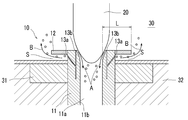
- FIG. 1 shows a main part of the tundish nozzle structure according to the embodiment of the present invention.
- the tundish upper nozzle structure 10 of the present embodiment is for continuous casting of steel whose flow rate of molten steel is controlled by a stopper 20, and the tundish upper nozzle 1 is provided on the entire circumference of the upper end portion of the tundish upper nozzle 11. It is provided with a flange-shaped object 12 having a size larger than the outer diameter (outer diameter) of the above. Further, the tundish upper nozzle structure 10 of the present embodiment is provided with a plurality of (six at equal intervals in the circumferential direction) gas discharge holes 13a on the outer peripheral surface of the tundish upper nozzle 11 below the flange-shaped object 12. ing.
- the tundish upper nozzle structure 10 of the present embodiment is also provided with a plurality of gas discharge holes 13b (24 at equal intervals in the circumferential direction) on the upper end surface of the tundish upper nozzle 11.
- the tundish upper nozzle structure 10 is a space through which gas can pass through a part or all of the lower surface of the flange-shaped object 10 when the tundish upper nozzle structure 10 is mounted on the tundish 30. It is equipped with S (the molten steel exists in this space because the tundish is filled with molten steel during casting).
- the molten steel flow velocity (direction of arrow A) to the outer peripheral side of the tundish upper nozzle 11, that is, the inner hole 11a is small.
- the gas can be directed upward from the vicinity of the region by guiding it to the region (direction of arrow B).
- the gas can be levitated in the tundish 30, and the effect of levitating inclusions in the tundish 30 can be obtained.
- the quality of slabs can be improved.
- the present inventors in such a tundish upper nozzle structure 10, the ratio of the flow rate of the gas downward on the inner hole 11a side to the amount of ascending into the tundish 30 is the length L shown in FIG. It was found that it largely depends on (mm) and the casting speed M (t / min).
- the length L shown in FIG. 1 is the length from the vertical position of the inner hole surface 11b at the lower end of the tundish upper nozzle 11 to the gas discharge hole or the outer peripheral surface on the upper surface of the flange-shaped object 12.
- Casting speed M (t / min) is synonymous with the throughput of molten steel.
- the length L is defined as the vertical position of the inner hole surface 11b at the lower end of the tundish upper nozzle 11, although the outer circumference and the vicinity of the upper end of the tundish upper nozzle may have various shapes, but the inner hole surface at the lower end.
- the position (almost the same as the inner hole diameter) does not fluctuate at the same casting speed, that is, there is no big difference in the speed of the molten steel flowing into the inner hole, and even in the case of stopper control, the fitting is performed. This is because the portion positions are substantially the same in the radial direction according to the diameter of the inner hole.
- the control of the inner hole side or the floating ratio of the gas in the present invention is performed for each gas discharged from each discharge hole. Therefore, if there are gas discharge holes on the upper surface of the brim-shaped object, which is one of the criteria for determining the length L (mm), the above-mentioned description for each of the individual discharge holes, regardless of whether one or more of them are present. If it is the length, or if the gas flows from either the lower part of the brim-shaped object or the outer peripheral surface and the gas is released upward on the outer peripheral surface of the brim-shaped object, it reaches the outer peripheral surface of the brim-shaped object. Refers to the length.
- the ratio of the inner hole side / levitation according to the above formula is determined by the L (mm) of each discharged gas. Whether or not to coexist and what to do with the number is related to the control of the gas discharge amount and form of the nozzle as a whole on the tundish, and this point may be set according to the individual operating conditions (optional).
- Equations 1 and 2 The right side of Equations 1 and 2 is graphed as shown in Fig. 2.
- the length L is in the region above this approximate line, almost all of the gas can be levitated in the tundish. If the area is less than the approximate line, the flow rate of the gas downward on the inner hole side and the amount of floating can be adjusted.
- the inner hole diameter of the tundish upper nozzle is 80 mm ⁇ , ⁇ As a stopper control, the space is about 15 mm for a diameter of 100 mm ⁇ of the fitting part when fully closed.
- the gas discharge hole is a through hole of 0.3 mm ⁇ (the bubble diameter is about 1.5 to 3.5 mm ⁇ as a result), ⁇ Casting speed is 3t / min And said.
- the bubble diameter is about 1.5 to 3.5 mm ⁇ , and in molten graphite, it is 2 to 3 times that, and this gas discharge hole.
- the present inventors have conducted experiments so far that the bubble diameters of a through hole of 0.3 mm ⁇ and an alumina-graphite porous body (so-called porous refractory, average pore diameter ⁇ 100 to 120 ⁇ m) are almost the same. , It is known from the results of actual operation.
- the length L (mm) can be made equal to or greater than the boundary length LB (mm) satisfying the above equation 3, and almost all of the gas can be levitated, or the boundary length LB (mm). ), The flow rate of the gas downward on the inner hole side and the amount of floating can be adjusted.
- the vertical axis L (mm) in FIG. 2 is the length from the vertical position of the lower end of the inner hole of the upper nozzle of the tundish, the length including the wall thickness of the flange-shaped object installation position of the upper nozzle structure of the tundish. That's right. Therefore, the case where the brim-shaped material has the above-mentioned wall thickness (mm) ⁇ LB (mm) is within the scope of the present invention. Further, in general (many) castings, the amount of gas floating often decreases when the casting speed per such tundish upper nozzle is about 3 (t / min) or more. Considering the actual situation, if the length L (mm) is about 60 mm or more, almost all the gas will float upward.
- L ⁇ 60 mm is required to float all the (13a) gas blown from the outer circumference upward, and in the case of L ⁇ 60 mm, the smaller L is, the more gas is required. This means that the flow rate downward on the inner hole side is increased (see FIG. 3).
- the brim-shaped object 12 is installed on the entire circumference of the upper end portion of the tundish upper nozzle 11, but may be installed on a part of the outer circumference of the upper end portion of the tundish upper nozzle 11. Even if the brim-shaped object 12 is installed at a part of the outer periphery of the upper end portion of the upper nozzle 11 of the tundish, the effect of floating the gas in the tundish (the effect of floating inclusions in the tundish) is not a little. can get. Further, the plan view shape of the brim-shaped object 12 is not limited to a circle, and may be, for example, an ellipse or a polygon.
- a plurality of gas discharge holes 13a are provided on the outer peripheral surface of the tundish upper nozzle 11 below the flange-shaped object 12 (six at equal intervals in the circumferential direction), but the gas discharge holes 13a are provided.
- One or more may be provided on any one or more of the lower surface, the outer peripheral surface, and the upper surface of the brim-shaped object 12.
- the gas discharge hole 13a of the collar-shaped object 12 is the end of the gas flow path, which is the space inside the collar-shaped object 12, or the lower surface of the collar-shaped object 12. It can be a hole that penetrates the upper surface.
- the lower surface of the brim-shaped object 12 is provided with a space S through which gas can pass, but the lower surface of the brim-shaped object 12 is provided with one or more grooves through which gas can pass. You can also prepare.
- the groove includes a form in which the lower surface of the collar-shaped object 12 is curved in the circumferential direction to make a part of the circumferential direction concave, and the concave portion extends in the radial direction. That is, the groove may have a structure as a gas flow path through which gas can be concentrated and flow toward the outer peripheral side. Further, a porous refractory having high gas permeability can be installed at the position of the space S instead of the space.
- the collar-shaped object 12 is joined to the tundish upper nozzle 11 by an adhesive, but it may be joined to the tundish upper nozzle 11 by a screw or a bionet structure. Further, the brim-shaped object 12 may be fitted to the outer periphery of the tundish upper nozzle 11 and joined to the tuyere 31 adjacent to the tundish upper nozzle 11 or the refractory layer 32 at the bottom of the tundish. The joining can be done with screws or bionet structures, or adhesives.
- the tundish upper nozzle structure 10 of the present embodiment is for continuous casting of steel whose flow rate of molten steel is controlled by a stopper 20, but is for continuous casting of steel whose flow rate of molten steel is controlled by a sliding nozzle device. You can also do it. That is, it can be applied to a structure in which there is no so-called obstacle that changes the flow of molten steel above the nozzle on the tundish.
- a conventional product in which the flange-shaped object 12 is not installed and a conventional product (comparative example) in which the flange-shaped object 12 is installed and the length L (mm) is 30 to 60 mm.
- the product of the present invention changed in the range of (Example)
- a continuous casting test of steel in which the flow rate of molten steel is controlled by a stopper was carried out.
- the number of surface defects was evaluated. Specifically, the alumina adhesion thickness in the tundish upper nozzle in the conventional product was set to 1.0, and the alumina adhesion thickness in the tundish upper nozzle in the present invention product was indexed.
- Table 1 shows the results of the continuous casting test. Since the casting speed (throughput of molten steel) is about 3 (t / min) in this continuous casting test, the boundary length LB in the above formula 3 is about 60 mm.
- the floating amount (ratio) of bubbles is an index with the total amount as 100, and is based on an estimated value (example) from visual inspection and water model experiments, etc., where 100 is almost all floating and 0 is all toward the inner hole side. Means the influx of.
- the product of the present invention (Example 3) in which L (mm) has a boundary length LB (about 60 mm) or more has a tundish upper nozzle as compared with the conventional product (Comparative Example 1).
- the thickness of alumina adhesion has decreased, and the number of surface defects on the coil has also decreased.
- the products of the present invention (Examples 1 and 2) in which L (mm) is less than the boundary length LB (about 60 mm)
- the amount of air bubbles floating / the amount on the inner hole side can be adjusted by adjusting L (mm). It shows that the proportions can be adjusted, which in turn can also adjust the quality of the slabs.
- Tundish upper nozzle structure 11 Tundish upper nozzle 11a Inner hole 11b Inner hole surface 12 Brim-shaped object 13a, 13b Gas discharge hole 20 Stopper 30 Tundish 31 Tuft 32 Tundish bottom refractory layer S space
Landscapes
- Engineering & Computer Science (AREA)
- Mechanical Engineering (AREA)
- Continuous Casting (AREA)
- Casting Support Devices, Ladles, And Melt Control Thereby (AREA)
- Valve Housings (AREA)
Abstract
Description
(1)タンディッシュ上ノズルの内孔から下方へ気泡を流動させることで,当該タンディッシュ上ノズルないしはその下方のノズルの内孔面への介在物の付着あるいは介在物の付着による内孔閉塞を抑制する。
(2)タンディッシュ上ノズルの下方からモールド内の溶鋼の流動形態を制御する。
(3)タンディッシュ上ノズルの下方ないしモールド内で介在物を浮上させる。
(4)タンディッシュ内で介在物を浮上させる。
これらは,鋳造操業の安定性や生産性,鋳片の品質に影響を及ぼす。
主に前記(1)~(3)に関して,
例えば,特許文献1には,タンディッシュ上ノズルの内孔にガス吐出用のポーラス部を設置すると共に,タンディッシュ上ノズルの上端部外周に設置したリング状耐火物の輪状鍔部がこのタンディッシュ上ノズルの上部を覆う構造が提案されている。これにより,タンディッシュ上ノズルの内孔へのガス供給を確実に行うことができるとされている。
特許文献3には,タンディッシュの底部に設けられたノズルの上部に設けられたリング状の上ポーラス耐火物から不活性ガスを吹き込むと共に,前記ノズルの下部に設けられたリング状の下ポーラス耐火物から不活性ガスを吹き込む連続鋳造方法が提案されている。これにより,上ポーラス耐火物は,不活性ガスをタンディッシュの溶鋼へ向けて吹き込むことができ,下ポーラス耐火物は,不活性ガスをノズルの開口に向けて吹き込むことができるとされている。
しかし,前記特許文献等の従来技術によるガス吹き込み方法等では,吹き込んだガスの殆どがタンディッシュ上ノズルの内孔側に流れてしまい,ガスを上方すなわちタンディッシュ内の溶鋼中に浮上させることができないことがわかった。
しかし,タンディッシュ上ノズル以外のタンディッシュ底部のいずれかの位置で,タンディッシュ内にガスを吹き込むためには,そのための専用の設備が必要であり,イニシャルコスト及びランニングコストが高くなり,また操業時の漏鋼等の危険性も増大する。
さらにはこの方法では溶鋼内介在物除去効果は十分ではないとも指摘されている。
このような観点から,タンディッシュ内でガスにより介在物を除去するには,タンディッシュ上ノズルを使用し,タンディッシュ内溶鋼へのガスの浮上流を形成し,またその割合を調整することが好ましい。
なお,一のタンディッシュ上ノズルには,吐出位置,多孔体又は貫通孔等の吐出孔の形態,吐出孔の数等が様々であり,本発明の「当該ノズルの特定場所から吹き込むガスの全て」とは一のガス流出部分,言い換えると「一の貫通孔から吐出するガスの全て,又は多孔体等を含む複数の吐出孔であっても吐出直後の複数の気泡が一つの気泡に合体するような,いわば気泡一つを形成するようなごく小さい吐出孔の集合部分それぞれに着目して,そこから吐出するガスの全て」という意味であって,一のタンディッシュ上ノズルから吐出するガス全てを対象とするものではない。
1.
タンディッシュ上ノズルの上端部外周の一部又は全周に,当該タンディッシュ上ノズル上端部の外形よりも大きい鍔状物を備え,前記鍔状物の下面,外周面,上面,及び前記鍔状物より下方の前記タンディッシュ上ノズルの外周面のいずれか一又は複数の面に,一又は複数のガス吐出孔を備えている,タンディッシュ上ノズル構造体。
2.
前記鍔状物のガス吐出孔は,当該鍔状物内の空間であるガス流通経路の端部又は当該鍔状物の下面から上面を貫通する孔である,前記1に記載のタンディッシュ上ノズル構造体。
3.
前記鍔状物の下面にはガスが通過することができる溝を一又は複数備えている,前記1又は2に記載のタンディッシュ上ノズル構造体。
4.
当該タンディッシュ上ノズル構造体をタンディッシュに装着した状態で,前記鍔状物の下面の一部又は全部にはガスが通過することができる空間を備えている,前記1又は2に記載のタンディッシュ上ノズル構造体。
5.
当該タンディッシュ上ノズル構造体は,ストッパーにより溶鋼の流量制御を行う鋼の連続鋳造用であって,
前記タンディッシュ上ノズルの下端の内孔面の鉛直位置から前記鍔状物の上面のガス吐出孔又は外周面までの長さL(mm)が,下記の式1を充足する,前記1から4のいずれか一項に記載のタンディッシュ上ノズル構造体。
L ≧ -1.875M2+26.332M-0.3929 ・・・式1
ここで,
M:鋳造速度(t/min)
6.
当該タンディッシュ上ノズル構造体は,ストッパーにより溶鋼の流量制御を行う鋼の連続鋳造用であって,
前記タンディッシュ上ノズルの下端の内孔面の鉛直位置から前記鍔状物の上面のガス吐出孔又は外周面までの長さL(mm)が,下記の式2を充足する,前記1から4のいずれか一項に記載のタンディッシュ上ノズル構造体。
L < -1.875M2+26.332M-0.3929 ・・・式2
ここで,
M:鋳造速度(t/min)
7.
前記タンディッシュ上ノズルの下端の内孔面の鉛直位置から前記鍔状物の上面のガス吐出孔又は外周面までの長さL(mm)が,60mm以上である,前記1から5のいずれか一項に記載のタンディッシュ上ノズル構造体。
8.
前記鍔状物は,前記タンディッシュ上ノズルに接合している,前記1から7のいずれか一項に記載のタンディッシュ上ノズル構造体。
9.
前記鍔状物と前記タンディッシュ上ノズルとが,ネジ若しくはバイオネット構造,又は接着材により接合している,前記8に記載のタンディッシュ上ノズル構造体。
10.
前記鍔状物は,前記タンディッシュ上ノズルの外周に嵌合し,当該タンディッシュ上ノズルと隣接する羽口又はタンディッシュ底部耐火物層に接合している,前記1から7のいずれか一項に記載のタンディッシュ上ノズル構造体。
11.
前記鍔状物と前記羽口又は前記タンディッシュ底部耐火物層とが,ネジ若しくはバイオネット構造,又は接着材により接合している,前記10に記載のタンディッシュ上ノズル構造体。
12.
前記1から4のいずれか一項に記載のタンディッシュ上ノズル構造体を用いる連続鋳造方法において,
前記タンディッシュ上ノズル構造体は,ストッパーにより溶鋼の流量制御を行う鋼の連続鋳造用であり,
前記タンディッシュ上ノズルの下端の内孔面の鉛直位置から前記鍔状物の上面のガス吐出孔又は外周面までの長さL(mm)を,下記の式3を充足する境界長さLB(mm)以上にしてガスのほぼ全てを浮上させる,又は前記境界長さLB(mm)未満にしてガスの内孔側下方への流量と浮上する量とを調整する,連続鋳造方法。
LB = -1.875M2+26.332M-0.3929 ・・・式3
ここで,
M:鋳造速度(t/min)
また,当該タンディッシュ上ノズルの外形よりも大きい鍔状物の,内孔下端の鉛直位置からガス吐出孔又は鍔状物に沿って流動した後に上方に解放される部位までのガス吐出部分までの長さ(前記L)を任意に調節することで,個別の操業等に応じてガスのノズル内孔側下方への流量とタンディッシュ内への浮上流量とを任意に調節することができる。
本実施形態のタンディッシュ上ノズル構造体10は,ストッパー20により溶鋼の流量制御を行う鋼の連続鋳造用であり,タンディッシュ上ノズル11の上端部外周の全周に,このタンディッシュ上ノズル1の外形(外径)よりも大きい鍔状物12を備えている。また,本実施形態のタンディッシュ上ノズル構造体10は,鍔状物12より下方のタンディッシュ上ノズル11の外周面に,複数(周方向に等間隔で6個)のガス吐出孔13aを備えている。さらに,本実施形態のタンディッシュ上ノズル構造体10は,タンディッシュ上ノズル11の上端面にも,複数(周方向に等間隔で24個)のガス吐出孔13bを備えている。
なお,タンディッシュ上ノズル構造体10は,図1に示すように,これをタンディッシュ30に装着した状態で,鍔状物10の下面の一部又は全部にはガスが通過することができる空間S(鋳造中はタンディッシュ内に溶鋼が充満するので,この空間には溶鋼が存在する)を備えている。
L ≧ -1.875M2+26.332M-0.3929 ・・・式1
L < -1.875M2+26.332M-0.3929 ・・・式2
したがって,この長さL(mm)を決定する一方の基準となる前記鍔状物の上面にガス吐出孔が有る場合は,一又は複数存在するかに関わらずその個々の吐出孔ごとに関する前記の長さであり,又は前記鍔状物の下方のいずれか若しくは外周面からガスが流動して鍔状物の外周面でガスが上方に解放される場合は,その鍔状物の外周面までの長さを指す。
これらが併存していても,それぞれの吐出ガスはそのL(mm)によってそれぞれ前記式による内孔側/浮上の割合が決定付けられる。併存させるか否か,数をどうするかはタンディッシュ上ノズル全体としてのガスの吐出量や形態の制御に関するのであって,この点は個別の操業条件(任意)に応じて設定すればよい。
・タンディッシュ上ノズルの内孔径を80mmφ,
・ストッパー制御として全閉時の嵌合部の径100mmφに対し空間を約12mm,
・ガス吐出孔は0.3mmφの貫通孔,→13b(24孔),13a(6孔)
・気泡径を3.5mmφ,
・鋳造速度は0~5t/min
とした。
さらに,次の条件での水モデル実験を行った。
・タンディッシュ上ノズルの内孔径を80mmφ,
・ストッパー制御として全閉時の嵌合部の径100mmφに対し空間を約15mm,
・ガス吐出孔は0.3mmφの貫通孔(気泡径は結果として約1.5~3.5mmφ),
・鋳造速度は3t/min
とした。
LB = -1.875M2+26.332M-0.3929 ・・・式3
また,一般的(多くの)鋳造においては,このようなタンディッシュ上ノズル一つあたりの鋳造速度が約3(t/min)以上の場合にガスの浮上量が減少することが多く,このような実態を考慮すると,長さL(mm)がほぼ60mm以上であれば,ほぼ全てのガスが上方に浮上することになる。
すなわち一般的(多くの)鋳造においては,外周から吹き込んだ(13a)ガスを全て上方に浮上させるには,L≧60mmが必要であり,また,L<60mmの場合,Lが小さくなるほど,ガスの内孔側下方への流量が多くなるということである(図3参照)。
(A)本実施形態において鍔状物12は,タンディッシュ上ノズル11の上端部外周の全周に設置したが,タンディッシュ上ノズル11の上端部外周の一部に設置してもよい。鍔状物12の設置位置がタンディッシュ上ノズル11の上端部外周の一部であったとしても,ガスをタンディッシュ内に浮上させる効果(タンディッシュ内で介在物を浮上させる効果)は少なからず得られる。
また,鍔状物12の平面視形状は円形に限らず,例えば楕円形や多角形であってよい。
また,前記溝には,鍔状物12の下面を円周方向に湾曲させて円周方向の一部を凹状にし,その凹状部を半径方向に向かって延在させた形態を含む。すなわち前記溝は,ガスが集中して外周側方向に流動することができるガス流通経路としての構造を備えていればよい。
さらに前記空間Sの位置に空間に換えてガス透過性の高い多孔性の耐火物を設置することもできる。
また鍔状物12は,タンディッシュ上ノズル11の外周に嵌合し,このタンディッシュ上ノズル11と隣接する羽口31又はタンディッシュ底部耐火物層32に接合してもよい。その接合は,ネジ若しくはバイオネット構造,又は接着材により行うことができる。
・鋼種 : 一般アルミキルド鋼
・鋳造サイズ : 250mm(厚)×1250mm(幅)
・鋳造速度(溶鋼のスループット) : 約3(t/min)
<タンディッシュ上ノズル条件>
・内孔径:80mm
・ガス吐出孔の径×数 : 0.3(mm)× 13b(24孔),13a(6孔)
・ガス(Ar)吐出量 : 10(L/min)
・ガス(Ar)吐出流速 : 1.56(m/min)

なお,L(mm)が境界長さLB(約60mm)未満である本発明品(実施例1,2)については,L(mm)を調整することで気泡の浮上量/内孔側量の割合を調整することができ,それが鋳片の品質をも調整することができることを示している。
11 タンディッシュ上ノズル
11a 内孔
11b 内孔面
12 鍔状物
13a,13b ガス吐出孔
20 ストッパー
30 タンディッシュ
31 羽口
32 タンディッシュ底部耐火物層
S 空間
Claims (12)
- タンディッシュ上ノズルの上端部外周の一部又は全周に,当該タンディッシュ上ノズル上端部の外形よりも大きい鍔状物を備え,前記鍔状物の下面,外周面,上面,及び前記鍔状物より下方の前記タンディッシュ上ノズルの外周面のいずれか一又は複数の面に,一又は複数のガス吐出孔を備えている,タンディッシュ上ノズル構造体。
- 前記鍔状物のガス吐出孔は,当該鍔状物内の空間であるガス流通経路の端部又は当該鍔状物の下面から上面を貫通する孔である,請求項1に記載のタンディッシュ上ノズル構造体。
- 前記鍔状物の下面にはガスが通過することができる溝を一又は複数備えている,請求項1又は2に記載のタンディッシュ上ノズル構造体。
- 当該タンディッシュ上ノズル構造体をタンディッシュに装着した状態で,前記鍔状物の下面の一部又は全部にはガスが通過することができる空間を備えている,請求項1又は2に記載のタンディッシュ上ノズル構造体。
- 当該タンディッシュ上ノズル構造体は,ストッパーにより溶鋼の流量制御を行う鋼の連続鋳造用であって,
前記タンディッシュ上ノズルの下端の内孔面の鉛直位置から前記鍔状物の上面のガス吐出孔又は外周面までの長さL(mm)が,下記の式1を充足する,請求項1から4のいずれか一項に記載のタンディッシュ上ノズル構造体。
L ≧ -1.875M2+26.332M-0.3929 ・・・式1
ここで,
M:鋳造速度(t/min) - 当該タンディッシュ上ノズル構造体は,ストッパーにより溶鋼の流量制御を行う鋼の連続鋳造用であって,
前記タンディッシュ上ノズルの下端の内孔面の鉛直位置から前記鍔状物の上面のガス吐出孔又は外周面までの長さL(mm)が,下記の式2を充足する,請求項1から4のいずれか一項に記載のタンディッシュ上ノズル構造体。
L < -1.875M2+26.332M-0.3929 ・・・式2
ここで,
M:鋳造速度(t/min) - 前記タンディッシュ上ノズルの下端の内孔面の鉛直位置から前記鍔状物の上面のガス吐出孔又は外周面までの長さL(mm)が,60mm以上である,請求項1から5のいずれか一項に記載のタンディッシュ上ノズル構造体。
- 前記鍔状物は,前記タンディッシュ上ノズルに接合している,請求項1から7のいずれか一項に記載のタンディッシュ上ノズル構造体。
- 前記鍔状物と前記タンディッシュ上ノズルとが,ネジ若しくはバイオネット構造,又は接着材により接合している,請求項8に記載のタンディッシュ上ノズル構造体。
- 前記鍔状物は,前記タンディッシュ上ノズルの外周に嵌合し,当該タンディッシュ上ノズルと隣接する羽口又はタンディッシュ底部耐火物層に接合している,請求項1から7のいずれか一項に記載のタンディッシュ上ノズル構造体。
- 前記鍔状物と前記羽口又は前記タンディッシュ底部耐火物層とが,ネジ若しくはバイオネット構造,又は接着材により接合している,請求項10に記載のタンディッシュ上ノズル構造体。
- 請求項1から4のいずれか一項に記載のタンディッシュ上ノズル構造体を用いる連続鋳造方法において,
前記タンディッシュ上ノズル構造体は,ストッパーにより溶鋼の流量制御を行う鋼の連続鋳造用であり,
前記タンディッシュ上ノズルの下端の内孔面の鉛直位置から前記鍔状物の上面のガス吐出孔又は外周面までの長さL(mm)を,下記の式3を充足する境界長さLB(mm)以上にしてガスのほぼ全てを浮上させる,又は前記境界長さLB(mm)未満にしてガスの内孔側下方への流量と浮上する量とを調整する,連続鋳造方法。
LB = -1.875M2+26.332M-0.3929 ・・・式3
ここで,
M:鋳造速度(t/min)
Priority Applications (4)
| Application Number | Priority Date | Filing Date | Title |
|---|---|---|---|
| US17/639,848 US20220324017A1 (en) | 2019-09-26 | 2020-09-17 | Tundish upper nozzle structure and continuous casting method |
| BR112022001629A BR112022001629A2 (pt) | 2019-09-26 | 2020-09-17 | Estrutura de válvula superior de distribuidor, e, método de lingotamento contínuo |
| CN202080046023.XA CN114040823A (zh) | 2019-09-26 | 2020-09-17 | 浇口盘上喷嘴结构体及连续铸造方法 |
| EP20868567.7A EP4035795A4 (en) | 2019-09-26 | 2020-09-17 | MANIFOLD NOZZLE STRUCTURE AND CONTINUOUS CASTING PROCESS |
Applications Claiming Priority (2)
| Application Number | Priority Date | Filing Date | Title |
|---|---|---|---|
| JP2019-175256 | 2019-09-26 | ||
| JP2019175256A JP2021049564A (ja) | 2019-09-26 | 2019-09-26 | タンディッシュ上ノズル構造体及び連続鋳造方法 |
Publications (1)
| Publication Number | Publication Date |
|---|---|
| WO2021060122A1 true WO2021060122A1 (ja) | 2021-04-01 |
Family
ID=75155231
Family Applications (1)
| Application Number | Title | Priority Date | Filing Date |
|---|---|---|---|
| PCT/JP2020/035165 Ceased WO2021060122A1 (ja) | 2019-09-26 | 2020-09-17 | タンディッシュ上ノズル構造体及び連続鋳造方法 |
Country Status (7)
| Country | Link |
|---|---|
| US (1) | US20220324017A1 (ja) |
| EP (1) | EP4035795A4 (ja) |
| JP (1) | JP2021049564A (ja) |
| CN (1) | CN114040823A (ja) |
| BR (1) | BR112022001629A2 (ja) |
| TW (1) | TWI770616B (ja) |
| WO (1) | WO2021060122A1 (ja) |
Citations (9)
| Publication number | Priority date | Publication date | Assignee | Title |
|---|---|---|---|---|
| EP0059805A1 (en) * | 1981-03-11 | 1982-09-15 | Junichi Ato | Porous nozzle for molten metal vessel |
| US4360190A (en) * | 1981-03-16 | 1982-11-23 | Junichi Ato | Porous nozzle for molten metal vessel |
| JPH01284473A (ja) * | 1988-05-11 | 1989-11-15 | Toshiba Ceramics Co Ltd | 溶融金属排出装置 |
| JPH054933Y2 (ja) * | 1987-08-27 | 1993-02-08 | ||
| JPH06297118A (ja) | 1993-04-12 | 1994-10-25 | Nippon Steel Corp | タンディッシュ底部のストッパー受けノズル |
| JP2000254772A (ja) * | 1999-03-09 | 2000-09-19 | Nisshin Steel Co Ltd | タンディッシュノズル部の構造 |
| JP2003220450A (ja) | 2002-01-28 | 2003-08-05 | Nisshin Steel Co Ltd | タンディッシュノズル構造 |
| JP2006061943A (ja) * | 2004-08-26 | 2006-03-09 | Kurosaki Harima Corp | ガスを吹き出す機能を有する溶融金属排出ノズル |
| JP2016182612A (ja) | 2015-03-25 | 2016-10-20 | 株式会社神戸製鋼所 | 上ポーラス耐火物及び下ポーラス耐火物から不活性ガスを吹き込む連続鋳造方法 |
Family Cites Families (14)
| Publication number | Priority date | Publication date | Assignee | Title |
|---|---|---|---|---|
| FR2516415A1 (fr) * | 1981-11-13 | 1983-05-20 | Daussan & Co | Dispositif pour eliminer les inclusions contenues dans les metaux liquides |
| GB2149699B (en) * | 1983-11-18 | 1987-03-11 | Uss Eng & Consult | Method and apparatus for avoiding vortexing in a bottom pour vessel |
| CH657075A5 (de) * | 1984-11-26 | 1986-08-15 | Cometus Ag | Verfahren zum spuelen von metallschmelzen, mit einem durch einen spuelstein gefuehrten gas, und spuelstein zur ausfuehrung des verfahrens. |
| JPH04100662A (ja) * | 1990-08-20 | 1992-04-02 | Kawasaki Refract Co Ltd | 溶融金属容器の溶湯流出方法 |
| GB9212953D0 (en) * | 1992-06-18 | 1992-07-29 | Foseco Int | Purifying molten metal |
| US5723055A (en) * | 1995-10-10 | 1998-03-03 | Vesuvius Crucible Company | Nozzle assembly having inert gas distributor |
| GB9522217D0 (en) * | 1995-10-31 | 1996-01-03 | Shaw Richard D | Gas-porous nozzle |
| JPH09314294A (ja) * | 1996-05-28 | 1997-12-09 | Akechi Ceramics Kk | 連続鋳造用浸漬ノズル |
| JPH1034299A (ja) * | 1996-07-26 | 1998-02-10 | Nippon Steel Corp | 注入装置 |
| FR2765126B1 (fr) * | 1997-06-26 | 1999-07-30 | Lorraine Laminage | Procede de coulee de metal liquide dans un conduit comprenant au moins deux pieces refractaires |
| WO2013081113A1 (ja) * | 2011-12-01 | 2013-06-06 | 黒崎播磨株式会社 | 耐火物及び鋳造用ノズル |
| JP6515388B2 (ja) * | 2015-10-02 | 2019-05-22 | 日本製鉄株式会社 | 連続鋳造用の上ノズル |
| JP6663230B2 (ja) * | 2016-01-25 | 2020-03-11 | 黒崎播磨株式会社 | ノズル構造体 |
| JP6649795B2 (ja) * | 2016-02-19 | 2020-02-19 | 黒崎播磨株式会社 | 浸漬ノズルの交換方法 |
-
2019
- 2019-09-26 JP JP2019175256A patent/JP2021049564A/ja active Pending
-
2020
- 2020-09-17 CN CN202080046023.XA patent/CN114040823A/zh active Pending
- 2020-09-17 EP EP20868567.7A patent/EP4035795A4/en not_active Withdrawn
- 2020-09-17 BR BR112022001629A patent/BR112022001629A2/pt not_active IP Right Cessation
- 2020-09-17 US US17/639,848 patent/US20220324017A1/en not_active Abandoned
- 2020-09-17 WO PCT/JP2020/035165 patent/WO2021060122A1/ja not_active Ceased
- 2020-09-24 TW TW109133031A patent/TWI770616B/zh not_active IP Right Cessation
Patent Citations (9)
| Publication number | Priority date | Publication date | Assignee | Title |
|---|---|---|---|---|
| EP0059805A1 (en) * | 1981-03-11 | 1982-09-15 | Junichi Ato | Porous nozzle for molten metal vessel |
| US4360190A (en) * | 1981-03-16 | 1982-11-23 | Junichi Ato | Porous nozzle for molten metal vessel |
| JPH054933Y2 (ja) * | 1987-08-27 | 1993-02-08 | ||
| JPH01284473A (ja) * | 1988-05-11 | 1989-11-15 | Toshiba Ceramics Co Ltd | 溶融金属排出装置 |
| JPH06297118A (ja) | 1993-04-12 | 1994-10-25 | Nippon Steel Corp | タンディッシュ底部のストッパー受けノズル |
| JP2000254772A (ja) * | 1999-03-09 | 2000-09-19 | Nisshin Steel Co Ltd | タンディッシュノズル部の構造 |
| JP2003220450A (ja) | 2002-01-28 | 2003-08-05 | Nisshin Steel Co Ltd | タンディッシュノズル構造 |
| JP2006061943A (ja) * | 2004-08-26 | 2006-03-09 | Kurosaki Harima Corp | ガスを吹き出す機能を有する溶融金属排出ノズル |
| JP2016182612A (ja) | 2015-03-25 | 2016-10-20 | 株式会社神戸製鋼所 | 上ポーラス耐火物及び下ポーラス耐火物から不活性ガスを吹き込む連続鋳造方法 |
Non-Patent Citations (1)
| Title |
|---|
| See also references of EP4035795A4 |
Also Published As
| Publication number | Publication date |
|---|---|
| TWI770616B (zh) | 2022-07-11 |
| JP2021049564A (ja) | 2021-04-01 |
| TW202128310A (zh) | 2021-08-01 |
| CN114040823A (zh) | 2022-02-11 |
| US20220324017A1 (en) | 2022-10-13 |
| BR112022001629A2 (pt) | 2022-04-19 |
| EP4035795A1 (en) | 2022-08-03 |
| EP4035795A4 (en) | 2023-02-08 |
Similar Documents
| Publication | Publication Date | Title |
|---|---|---|
| WO2013190799A1 (ja) | 高清浄度鋼鋳片の製造方法及びタンディッシュ | |
| KR101667674B1 (ko) | 스토퍼 | |
| JP2011143449A (ja) | 連続鋳造用タンディッシュにおける介在物除去方法 | |
| JP6577841B2 (ja) | 浸漬ノズル | |
| US20250205777A1 (en) | Immersion nozzle, mold, and continuous casting method of steel | |
| TW201615305A (zh) | 用於分配高質量流量的薄板噴嘴 | |
| CZ160694A3 (en) | Inlet system of aluminium continuous casting apparatus | |
| WO2020137722A1 (ja) | 連続鋳造用のストッパー及び連続鋳造方法 | |
| JP2021049564A (ja) | タンディッシュ上ノズル構造体及び連続鋳造方法 | |
| JP2022189431A (ja) | 鋼の連続鋳造方法 | |
| US11235384B2 (en) | Sliding nozzle | |
| JP2018058097A (ja) | 浸漬ノズル、連続鋳造機及び連続鋳造方法 | |
| JP5249425B2 (ja) | タンディッシュのインパクトパッド | |
| JP6630157B2 (ja) | 浸漬ノズル | |
| JP2023143363A (ja) | ロングノズル及びノズルシステム | |
| JP7031463B2 (ja) | 連続鋳造方法 | |
| KR20240034747A (ko) | 침지 노즐 | |
| JPH05200507A (ja) | 連続鋳造用ロングノズル | |
| TW202529911A (zh) | 連續鑄造用浸漬噴嘴及鋼之連續鑄造方法 | |
| JP5161814B2 (ja) | 連続鋳造用浸漬ノズル | |
| KR101969105B1 (ko) | 노즐 | |
| JP2017196643A (ja) | 下部ノズル | |
| JP2000301298A (ja) | 鋳型内の溶鋼流動制御方法 | |
| JP4421136B2 (ja) | 連続鋳造方法 | |
| JP2010005691A (ja) | 鋼の連続鋳造方法 |
Legal Events
| Date | Code | Title | Description |
|---|---|---|---|
| 121 | Ep: the epo has been informed by wipo that ep was designated in this application |
Ref document number: 20868567 Country of ref document: EP Kind code of ref document: A1 |
|
| REG | Reference to national code |
Ref country code: BR Ref legal event code: B01A Ref document number: 112022001629 Country of ref document: BR |
|
| NENP | Non-entry into the national phase |
Ref country code: DE |
|
| ENP | Entry into the national phase |
Ref document number: 112022001629 Country of ref document: BR Kind code of ref document: A2 Effective date: 20220128 |
|
| ENP | Entry into the national phase |
Ref document number: 2020868567 Country of ref document: EP Effective date: 20220426 |