WO2021065355A1 - Matériau réfractaire - Google Patents
Matériau réfractaire Download PDFInfo
- Publication number
- WO2021065355A1 WO2021065355A1 PCT/JP2020/033680 JP2020033680W WO2021065355A1 WO 2021065355 A1 WO2021065355 A1 WO 2021065355A1 JP 2020033680 W JP2020033680 W JP 2020033680W WO 2021065355 A1 WO2021065355 A1 WO 2021065355A1
- Authority
- WO
- WIPO (PCT)
- Prior art keywords
- sic
- glass layer
- refractory
- mass
- base material
- Prior art date
- Legal status (The legal status is an assumption and is not a legal conclusion. Google has not performed a legal analysis and makes no representation as to the accuracy of the status listed.)
- Ceased
Links
Images


Classifications
-
- C—CHEMISTRY; METALLURGY
- C04—CEMENTS; CONCRETE; ARTIFICIAL STONE; CERAMICS; REFRACTORIES
- C04B—LIME, MAGNESIA; SLAG; CEMENTS; COMPOSITIONS THEREOF, e.g. MORTARS, CONCRETE OR LIKE BUILDING MATERIALS; ARTIFICIAL STONE; CERAMICS; REFRACTORIES; TREATMENT OF NATURAL STONE
- C04B35/00—Shaped ceramic products characterised by their composition; Ceramics compositions; Processing powders of inorganic compounds preparatory to the manufacturing of ceramic products
- C04B35/66—Monolithic refractories or refractory mortars, including those whether or not containing clay
-
- C—CHEMISTRY; METALLURGY
- C04—CEMENTS; CONCRETE; ARTIFICIAL STONE; CERAMICS; REFRACTORIES
- C04B—LIME, MAGNESIA; SLAG; CEMENTS; COMPOSITIONS THEREOF, e.g. MORTARS, CONCRETE OR LIKE BUILDING MATERIALS; ARTIFICIAL STONE; CERAMICS; REFRACTORIES; TREATMENT OF NATURAL STONE
- C04B35/00—Shaped ceramic products characterised by their composition; Ceramics compositions; Processing powders of inorganic compounds preparatory to the manufacturing of ceramic products
- C04B35/515—Shaped ceramic products characterised by their composition; Ceramics compositions; Processing powders of inorganic compounds preparatory to the manufacturing of ceramic products based on non-oxide ceramics
- C04B35/56—Shaped ceramic products characterised by their composition; Ceramics compositions; Processing powders of inorganic compounds preparatory to the manufacturing of ceramic products based on non-oxide ceramics based on carbides or oxycarbides
- C04B35/565—Shaped ceramic products characterised by their composition; Ceramics compositions; Processing powders of inorganic compounds preparatory to the manufacturing of ceramic products based on non-oxide ceramics based on carbides or oxycarbides based on silicon carbide
-
- C—CHEMISTRY; METALLURGY
- C04—CEMENTS; CONCRETE; ARTIFICIAL STONE; CERAMICS; REFRACTORIES
- C04B—LIME, MAGNESIA; SLAG; CEMENTS; COMPOSITIONS THEREOF, e.g. MORTARS, CONCRETE OR LIKE BUILDING MATERIALS; ARTIFICIAL STONE; CERAMICS; REFRACTORIES; TREATMENT OF NATURAL STONE
- C04B41/00—After-treatment of mortars, concrete, artificial stone or ceramics; Treatment of natural stone
- C04B41/009—After-treatment of mortars, concrete, artificial stone or ceramics; Treatment of natural stone characterised by the material treated
-
- C—CHEMISTRY; METALLURGY
- C04—CEMENTS; CONCRETE; ARTIFICIAL STONE; CERAMICS; REFRACTORIES
- C04B—LIME, MAGNESIA; SLAG; CEMENTS; COMPOSITIONS THEREOF, e.g. MORTARS, CONCRETE OR LIKE BUILDING MATERIALS; ARTIFICIAL STONE; CERAMICS; REFRACTORIES; TREATMENT OF NATURAL STONE
- C04B41/00—After-treatment of mortars, concrete, artificial stone or ceramics; Treatment of natural stone
- C04B41/45—Coating or impregnating, e.g. injection in masonry, partial coating of green or fired ceramics, organic coating compositions for adhering together two concrete elements
- C04B41/50—Coating or impregnating, e.g. injection in masonry, partial coating of green or fired ceramics, organic coating compositions for adhering together two concrete elements with inorganic materials
- C04B41/5022—Coating or impregnating, e.g. injection in masonry, partial coating of green or fired ceramics, organic coating compositions for adhering together two concrete elements with inorganic materials with vitreous materials
-
- C—CHEMISTRY; METALLURGY
- C04—CEMENTS; CONCRETE; ARTIFICIAL STONE; CERAMICS; REFRACTORIES
- C04B—LIME, MAGNESIA; SLAG; CEMENTS; COMPOSITIONS THEREOF, e.g. MORTARS, CONCRETE OR LIKE BUILDING MATERIALS; ARTIFICIAL STONE; CERAMICS; REFRACTORIES; TREATMENT OF NATURAL STONE
- C04B41/00—After-treatment of mortars, concrete, artificial stone or ceramics; Treatment of natural stone
- C04B41/53—After-treatment of mortars, concrete, artificial stone or ceramics; Treatment of natural stone involving the removal of at least part of the materials of the treated article, e.g. etching, drying of hardened concrete
-
- C—CHEMISTRY; METALLURGY
- C04—CEMENTS; CONCRETE; ARTIFICIAL STONE; CERAMICS; REFRACTORIES
- C04B—LIME, MAGNESIA; SLAG; CEMENTS; COMPOSITIONS THEREOF, e.g. MORTARS, CONCRETE OR LIKE BUILDING MATERIALS; ARTIFICIAL STONE; CERAMICS; REFRACTORIES; TREATMENT OF NATURAL STONE
- C04B41/00—After-treatment of mortars, concrete, artificial stone or ceramics; Treatment of natural stone
- C04B41/80—After-treatment of mortars, concrete, artificial stone or ceramics; Treatment of natural stone of only ceramics
- C04B41/81—Coating or impregnation
- C04B41/85—Coating or impregnation with inorganic materials
- C04B41/86—Glazes; Cold glazes
-
- C—CHEMISTRY; METALLURGY
- C04—CEMENTS; CONCRETE; ARTIFICIAL STONE; CERAMICS; REFRACTORIES
- C04B—LIME, MAGNESIA; SLAG; CEMENTS; COMPOSITIONS THEREOF, e.g. MORTARS, CONCRETE OR LIKE BUILDING MATERIALS; ARTIFICIAL STONE; CERAMICS; REFRACTORIES; TREATMENT OF NATURAL STONE
- C04B41/00—After-treatment of mortars, concrete, artificial stone or ceramics; Treatment of natural stone
- C04B41/80—After-treatment of mortars, concrete, artificial stone or ceramics; Treatment of natural stone of only ceramics
- C04B41/81—Coating or impregnation
- C04B41/85—Coating or impregnation with inorganic materials
- C04B41/87—Ceramics
-
- C—CHEMISTRY; METALLURGY
- C04—CEMENTS; CONCRETE; ARTIFICIAL STONE; CERAMICS; REFRACTORIES
- C04B—LIME, MAGNESIA; SLAG; CEMENTS; COMPOSITIONS THEREOF, e.g. MORTARS, CONCRETE OR LIKE BUILDING MATERIALS; ARTIFICIAL STONE; CERAMICS; REFRACTORIES; TREATMENT OF NATURAL STONE
- C04B41/00—After-treatment of mortars, concrete, artificial stone or ceramics; Treatment of natural stone
- C04B41/80—After-treatment of mortars, concrete, artificial stone or ceramics; Treatment of natural stone of only ceramics
- C04B41/91—After-treatment of mortars, concrete, artificial stone or ceramics; Treatment of natural stone of only ceramics involving the removal of part of the materials of the treated articles, e.g. etching
-
- F—MECHANICAL ENGINEERING; LIGHTING; HEATING; WEAPONS; BLASTING
- F27—FURNACES; KILNS; OVENS; RETORTS
- F27D—DETAILS OR ACCESSORIES OF FURNACES, KILNS, OVENS OR RETORTS, IN SO FAR AS THEY ARE OF KINDS OCCURRING IN MORE THAN ONE KIND OF FURNACE
- F27D1/00—Casings; Linings; Walls; Roofs
-
- C—CHEMISTRY; METALLURGY
- C04—CEMENTS; CONCRETE; ARTIFICIAL STONE; CERAMICS; REFRACTORIES
- C04B—LIME, MAGNESIA; SLAG; CEMENTS; COMPOSITIONS THEREOF, e.g. MORTARS, CONCRETE OR LIKE BUILDING MATERIALS; ARTIFICIAL STONE; CERAMICS; REFRACTORIES; TREATMENT OF NATURAL STONE
- C04B2235/00—Aspects relating to ceramic starting mixtures or sintered ceramic products
- C04B2235/02—Composition of constituents of the starting material or of secondary phases of the final product
- C04B2235/30—Constituents and secondary phases not being of a fibrous nature
- C04B2235/42—Non metallic elements added as constituents or additives, e.g. sulfur, phosphor, selenium or tellurium
- C04B2235/428—Silicon
-
- C—CHEMISTRY; METALLURGY
- C04—CEMENTS; CONCRETE; ARTIFICIAL STONE; CERAMICS; REFRACTORIES
- C04B—LIME, MAGNESIA; SLAG; CEMENTS; COMPOSITIONS THEREOF, e.g. MORTARS, CONCRETE OR LIKE BUILDING MATERIALS; ARTIFICIAL STONE; CERAMICS; REFRACTORIES; TREATMENT OF NATURAL STONE
- C04B2235/00—Aspects relating to ceramic starting mixtures or sintered ceramic products
- C04B2235/65—Aspects relating to heat treatments of ceramic bodies such as green ceramics or pre-sintered ceramics, e.g. burning, sintering or melting processes
- C04B2235/656—Aspects relating to heat treatments of ceramic bodies such as green ceramics or pre-sintered ceramics, e.g. burning, sintering or melting processes characterised by specific heating conditions during heat treatment
-
- C—CHEMISTRY; METALLURGY
- C04—CEMENTS; CONCRETE; ARTIFICIAL STONE; CERAMICS; REFRACTORIES
- C04B—LIME, MAGNESIA; SLAG; CEMENTS; COMPOSITIONS THEREOF, e.g. MORTARS, CONCRETE OR LIKE BUILDING MATERIALS; ARTIFICIAL STONE; CERAMICS; REFRACTORIES; TREATMENT OF NATURAL STONE
- C04B2235/00—Aspects relating to ceramic starting mixtures or sintered ceramic products
- C04B2235/65—Aspects relating to heat treatments of ceramic bodies such as green ceramics or pre-sintered ceramics, e.g. burning, sintering or melting processes
- C04B2235/656—Aspects relating to heat treatments of ceramic bodies such as green ceramics or pre-sintered ceramics, e.g. burning, sintering or melting processes characterised by specific heating conditions during heat treatment
- C04B2235/6562—Heating rate
-
- C—CHEMISTRY; METALLURGY
- C04—CEMENTS; CONCRETE; ARTIFICIAL STONE; CERAMICS; REFRACTORIES
- C04B—LIME, MAGNESIA; SLAG; CEMENTS; COMPOSITIONS THEREOF, e.g. MORTARS, CONCRETE OR LIKE BUILDING MATERIALS; ARTIFICIAL STONE; CERAMICS; REFRACTORIES; TREATMENT OF NATURAL STONE
- C04B2235/00—Aspects relating to ceramic starting mixtures or sintered ceramic products
- C04B2235/65—Aspects relating to heat treatments of ceramic bodies such as green ceramics or pre-sintered ceramics, e.g. burning, sintering or melting processes
- C04B2235/656—Aspects relating to heat treatments of ceramic bodies such as green ceramics or pre-sintered ceramics, e.g. burning, sintering or melting processes characterised by specific heating conditions during heat treatment
- C04B2235/6567—Treatment time
-
- C—CHEMISTRY; METALLURGY
- C04—CEMENTS; CONCRETE; ARTIFICIAL STONE; CERAMICS; REFRACTORIES
- C04B—LIME, MAGNESIA; SLAG; CEMENTS; COMPOSITIONS THEREOF, e.g. MORTARS, CONCRETE OR LIKE BUILDING MATERIALS; ARTIFICIAL STONE; CERAMICS; REFRACTORIES; TREATMENT OF NATURAL STONE
- C04B2235/00—Aspects relating to ceramic starting mixtures or sintered ceramic products
- C04B2235/65—Aspects relating to heat treatments of ceramic bodies such as green ceramics or pre-sintered ceramics, e.g. burning, sintering or melting processes
- C04B2235/658—Atmosphere during thermal treatment
- C04B2235/6583—Oxygen containing atmosphere, e.g. with changing oxygen pressures
-
- C—CHEMISTRY; METALLURGY
- C04—CEMENTS; CONCRETE; ARTIFICIAL STONE; CERAMICS; REFRACTORIES
- C04B—LIME, MAGNESIA; SLAG; CEMENTS; COMPOSITIONS THEREOF, e.g. MORTARS, CONCRETE OR LIKE BUILDING MATERIALS; ARTIFICIAL STONE; CERAMICS; REFRACTORIES; TREATMENT OF NATURAL STONE
- C04B2235/00—Aspects relating to ceramic starting mixtures or sintered ceramic products
- C04B2235/70—Aspects relating to sintered or melt-casted ceramic products
- C04B2235/96—Properties of ceramic products, e.g. mechanical properties such as strength, toughness, wear resistance
Definitions
- Patent Document 1 Japanese Unexamined Patent Publication No. 2008-94652 discloses a refractory using a SiC-silicon substrate containing SiC particles as a main component and metallic Si between the SiC particles. .. Since the Si—SiC refractory has excellent thermal conductivity, a temperature difference is unlikely to occur in the refractory. Therefore, the Si—SiC refractory has an advantage that it can suppress damage due to thermal stress.
- the Si—SiC material base material is also excellent in heat resistance and fire resistance, and is promising as a material for producing a refractory material.
- a SiC-SiC refractory is produced by producing a SiC molded body, then bringing metallic Si into contact with the SiC molded body and heating it in an inert gas atmosphere under low pressure conditions.
- a Si component that is, a metallic Si or a Si compound that has not been impregnated in the SiC molding body remains. Therefore, in the case of a SiC-SiC refractory, a step of impregnating the inside of the SiC molding with metallic Si and then removing the Si component remaining on the surface is required.
- the surface of the SiC-SiC refractory may be scratched and cracks may occur starting from the scratch.
- the strength of the SiC-SiC refractory may decrease.
- the present specification provides a technique for suppressing a decrease in strength of a SiC-SiC refractory.
- the refractory material disclosed herein may include a SiC-SiC material base material and a glass layer.
- the SiC-SiC material base material is mainly composed of SiC particles, and metallic Si may be contained between the SiC particles.
- the glass layer may be mainly composed of SiO 2 that covers the surface of the SiC-silicon substrate.
- the mass ratio of the glass layer to the SiC-SiC material base material may be 0.001% by mass or more and 5% by mass or less.
- a flowchart for manufacturing a refractory is shown.
- An SEM photograph of the vicinity of the surface of the refractory is shown.
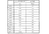
- the relationship between the mass ratio of the glass layer to the Si—SiC material substrate and the strength is shown.
- the refractory material disclosed in the present specification is used as a component constituting the firing furnace such as the inner wall of the firing furnace, or as a part used in the firing furnace such as a rack and a setter. Although not particularly limited, the refractory material disclosed in the present specification can be suitably used in an environment where the maximum temperature is 500 to 1350 ° C.
- the shape of the refractory may be flat plate, box, columnar, block, tubular or the like.
- the thickness of the refractory may be 0.1 to 20 mm.
- the refractory may include a SiC-silicon substrate and a glass layer that covers the surface of the SiC-SiC substrate.
- the conventional refractory made of a SiC material base material has a step of removing Si (or a Si compound) remaining on the surface after molding the SiC material fired body. Therefore, in the conventional refractory, even if a glass layer is formed on the surface in the process of producing the SiC-SiC refractory, the glass layer is also removed in the step of removing Si on the surface. That is, the refractory material made of the conventional SiC-SiC material base material does not have a glass layer on the surface.
- the surface of the SiC-silicon substrate By coating the surface of the SiC-silicon substrate with a glass layer, it is possible to prevent the refractory from being damaged starting from the recesses (scratches, etc.) on the surface of the SiC substrate.
- the surface of the SiC material base material by coating the surface of the SiC material base material with a glass layer, when stress is applied to the base material surface due to thermal expansion and contraction of the SiC material base material, the base material surface It is possible to suppress the concentration of stress in the recesses of the silicon and suppress the damage of the refractory.
- the SiC-SiC material base material is mainly composed of SiC particles, and metallic Si may be contained between the SiC particles.
- mainly SiC particles means that the ratio (mass%) of SiC particles to the SiC-SiC material base material is larger than 50% by mass.
- the ratio of SiC particles to the SiC-SiC material base material may be 55% by mass or more, 60% by mass or more, 70% by mass or more, and 80% by mass or more. May be.
- the size (average particle size) of the SiC particles may be 5 ⁇ m or more and 100 ⁇ m or less.
- the size (average particle size) of the SiC particles may be 10 ⁇ m or more, 20 ⁇ m or more, and 30 ⁇ m or more.
- the size of the SiC particles may be 80 ⁇ m or less, 70 ⁇ m or less, and 60 ⁇ m or less.
- the ratio (mass%) of metallic Si to the Si—SiC material base material may be 5 to 40% by mass. If the ratio of metallic Si to the SiC-silicon substrate is too small, the amount of voids between the SiC particles becomes large (the porosity of the SiC-silicon substrate is high), and the strength of the SiC-silicon substrate decreases. I have something to do. On the other hand, if the proportion of metallic Si in the SiC-silicon substrate is too large, cracks are likely to occur during use (when the refractory is exposed to high temperatures), and the strength of the SiC-silicon substrate becomes high. May decrease.
- the ratio of metallic Si to the SiC material base material is determined by the ratio of SiC particles to the SiC material base material.
- metallic Si is impregnated between the SiC particles so that the apparent porosity of the SiC-silicon substrate is 5% or less.
- the apparent porosity of the SiC-silicon substrate is more preferably 2% or less, and particularly preferably 1% or less.
- Concavities and convexities may be formed on the surface of the Si—SiC material base material.
- the surface roughness Rz (ISO 1997, JIS B 0601: 2001) of the unevenness on the surface of the SiC-silicon substrate may be 1 ⁇ m or more and 150 ⁇ m or less. By setting the surface roughness Rz of the unevenness to 1 ⁇ m or more, the adhesion between the SiC material base material and the glass layer is improved.
- the surface roughness Rz of the unevenness may be larger than the thickness (average thickness) of the glass layer, for example, 5 ⁇ m or more, 10 ⁇ m or more, 30 ⁇ m or more, 50 ⁇ m or more. You can.
- the surface roughness Rz of the unevenness may be 120 ⁇ m or less, 100 ⁇ m or less, 80 ⁇ m or less, and 60 ⁇ m or less.
- the SiC-SiC refractory has a step of impregnating the inside of the SiC molding with metallic Si and then removing the Si remaining on the surface.
- the irregularities on the surface of the Si—SiC material base material may be formed in the step of removing the Si component from the surface of the Si—SiC material base material, or may be performed separately from the step of removing the Si component.
- the surface of the Si—SiC material base material may be scratched in the step of removing the Si component, and cracks may occur starting from the scratches.
- the technique disclosed in the present specification can also be regarded as a technique for suppressing the occurrence of cracks in the fired product without removing the scratches generated in the step of removing the Si component.
- the glass layer may cover the entire surface of the SiC-silicon substrate.
- the thickness of the glass layer may be 0.1 ⁇ m or more and 150 ⁇ m or less.
- the effect of suppressing the occurrence of cracks can be sufficiently obtained.
- a force (stress) is applied from the glass layer to the SiC material base material to crack based on the difference in the coefficient of thermal expansion between the SiC material base material and the glass layer. Can be suppressed.
- the thickness (average thickness) of the glass layer is preferably thinner than the surface roughness Rz of the unevenness of the surface of the SiC material substrate, for example, it may be 100 ⁇ m or less, 60 ⁇ m or less, and 40 ⁇ m or less. May be.
- the thickness of the glass layer may be 0.5 ⁇ m or more, 1 ⁇ m or more, 5 ⁇ m or more, and 10 ⁇ m or more.
- the mass ratio of the glass layer to the Si—SiC material base material may be 0.001% by mass or more and 5% by mass or less. Within this range, the strength of the refractory can be improved and the occurrence of cracks can be suppressed. When the mass ratio is less than 0.001% by mass, it becomes difficult to obtain the effect of suppressing the occurrence of cracks. When the mass ratio exceeds 5% by mass, the ratio of the glass layer to the SiC-silicon substrate is too high, and it becomes difficult to obtain a high-strength refractory.
- the mass ratio of the glass layer to the Si—SiC material base material may be 0.003% by mass or more, 0.02% by mass or more, or 0.08% by mass or more. Further, the mass ratio of the glass layer to the SiC-SiC material base material may be 3% by mass or less, and may be 1% by mass or less.
- the mass ratio of the glass layer to the Si—SiC material base material can be calculated from the mass of the base material before the formation of the glass layer and the mass of the entire refractory after the formation of the glass layer, and the mass of both.
- the mass ratio of the glass layer to the SiC-silicon substrate is calculated by calculating the volume of the SiC-SiC substrate and the glass layer in the refractory from image analysis such as SEM and CT, and the SiC-SiC substrate and the glass.
- the masses of the SiC-silicon substrate and the glass layer can be calculated from the density of the layers, and can be calculated from the obtained masses of both.
- the glass layer may be mainly composed of SiO 2 , and may contain one or more of the elements Al, Ca, Fe, Na, K, Mg, Sr and Ba. That is, the glass layer may be a SiO 2 alone, it referred to as SiO 2 of more than 50 mass%, Al, Ca, Fe, Na, K, Mg, Sr, Ba elements (hereinafter, the auxiliary element ) Or a compound of the subcomponent element (for example, an oxide of the subcomponent element).
- the auxiliary element a compound of the subcomponent element
- the temperature at which the glass layer is formed can be lowered and the formation time can be shortened. That is, the glass layer containing the sub-component element can simplify the forming process as compared with the glass layer containing no sub-component element.
- the glass layer preferably contains one or more of the above-mentioned subcomponent elements, Al, Ca, Fe, Na and K elements (hereinafter, referred to as first subcomponent elements).
- the first subcomponent element (compound of the first subcomponent element) is relatively easily available and is chemically stable and therefore easy to handle.
- the subcomponent element may be present as a compound in the glass layer, and is particularly preferably present as an oxide.
- the glass layer can be formed by forming irregularities on the surface of the SiC-silicon substrate and then heating (firing) the SiC-SiC substrate in an oxidizing atmosphere.
- SiO 2 which is the main material of the glass layer, may be a partially oxidized version of Si constituting the SiC-silicon substrate, or the glass layer containing Si on the surface of the SiC-SiC substrate.
- the raw material for the glass layer may be arranged and the Si component contained in the raw material for the glass layer may be oxidized. When the glass layer contains the above-mentioned subcomponent elements, the raw material for the glass layer may contain the subcomponent elements.
- the raw material for the glass layer may be a solid such as powder or granular, or a fluid such as paste or liquid.
- the raw material for the glass layer is placed (coated) on the surface of the SiC material base material, and then the raw material for the glass layer is dried prior to heating (firing) in an oxidizing atmosphere. You may let me.
- the heating (baking) conditions for forming the glass layer depend on, for example, 900 to the desired thickness of the glass layer, the components contained in the glass layer, the presence or absence of the use of the raw material for the glass layer, and the type of the raw material for the glass layer. It may be adjusted at 1350 ° C. for 1 to 5 hours. Further, oxygen, ozone, carbon dioxide and the like can be used as the oxidizing gas to be introduced into the heating device (firing furnace).
- the object to be fired is a ceramic capacitor composed of barium titanate
- a zirconia compound or an yttria compound (Y 2 O 3) having low reactivity with barium titanate as the surface coating layer.
- a zirconia compound is selected as the surface coat layer
- a zirconia compound composed of at least one of stabilized zirconia stabilized with calcia (CaO) or yttria (Y 2 O 3 ), BaZrO 3 , and CaZrO 3 is to be fired.
- the optimum zirconia may be appropriately selected in consideration of the reactivity with respect to.
- a thermal spray coating containing a eutectic of alumina and zirconia can be used as the surface coat layer.
- the method for forming the surface coat layer is not particularly limited, and an appropriate optimum method such as a thermal spraying method or a spray coating method can be adopted.
- a zirconia compound is used as the surface coat layer, between the glass layer and the surface coat layer in order to suppress the occurrence of peeling due to the difference in thermal expansion between the SiC material base material and the zirconia surface coat layer.
- An intermediate layer of alumina or mullite may be provided on the surface.
- a flat-plate-shaped fired body of the SiC material base material is prepared (step S1), the Si component remaining on the surface of the SiC material fired body is removed, and unevenness is formed on the surface of the SiC material fired body.
- step S2 The apparent porosity of the Si—SiC material fired body was 2% or less.
- the surface roughness Rz (ISO 1997, JIS B 0601: 2001) of the surface of the Si—SiC material fired body was measured using a surface roughness meter (manufactured by Mitutoyo Co., Ltd .: SJ-210).
- the surface roughness Rz of the Si—SiC material fired body was 29 ⁇ m.
- the raw material for the glass layer was applied to the surface of the Si—SiC material fired body, the raw material for the glass layer was dried, and then the SiC material fired body was fired (step S3).
- a 10% NaCl aqueous solution was used as a raw material for the glass layer. Specifically, 10 g / m 2 of a 10% NaCl aqueous solution is applied to the entire surface of the SiC calcined product, dried at 100 ° C. for 1 hour in an air atmosphere, and glass is applied to the surface of the SiC calcined product. The raw material for the layer was fixed. Next, a SiC-silicon calcined body is placed in a calcining furnace in an air atmosphere, the temperature is raised to 1300 ° C.
- FIG. 2 shows an SEM photograph of the vicinity of the surface layer of the refractory.
- the glass layer covered the entire surface of the SiC-SiC material fired body.
- the average thickness of the glass layer was 6 ⁇ m, which was thinner than the surface roughness Rz of the Si—SiC material fired body. Therefore, unevenness was also confirmed on the surface of the refractory (the surface of the glass layer).
- the layer provided above the glass layer is a resin used when preparing a sample for taking an SEM photograph.
- Sample 2 had a predetermined temperature of 1200 ° C. and a predetermined time of 1 hour.
- Samples 3 to 12 were changed in a predetermined temperature and / or a predetermined time with respect to the sample 2 to change the amount of the glass layer deposited on the surface of the base material. Specifically, Samples 3 to 5 had a predetermined temperature lower than that of Sample 2, and / or a predetermined time was shortened. On the other hand, Samples 6 to 12 had a higher predetermined temperature and / or a longer predetermined time with respect to Sample 2.
- sample 1 was not calcined in an air atmosphere after obtaining a Si—SiC calcined body (the glass layer was not deposited).
- FIG. 3 shows the bending strength results of each sample.
- the samples (samples 2 to 11) in which the mass ratio of the glass layer to the SiC material base material is 0.001% by mass or more and 5% by mass or less can obtain high strength of 130 MPa or more.
- the samples (samples 2, 4 to 11) having a mass ratio of 0.003% by mass or more and 3% by mass or less can obtain higher strength (150 MPa or more).
Landscapes
- Chemical & Material Sciences (AREA)
- Engineering & Computer Science (AREA)
- Ceramic Engineering (AREA)
- Materials Engineering (AREA)
- Structural Engineering (AREA)
- Organic Chemistry (AREA)
- Manufacturing & Machinery (AREA)
- Inorganic Chemistry (AREA)
- Mechanical Engineering (AREA)
- General Engineering & Computer Science (AREA)
- Ceramic Products (AREA)
Abstract
Priority Applications (3)
| Application Number | Priority Date | Filing Date | Title |
|---|---|---|---|
| CN202080005371.2A CN114430733B (zh) | 2019-10-02 | 2020-09-04 | 耐火物 |
| JP2021511676A JP7225376B2 (ja) | 2019-10-02 | 2020-09-04 | 耐火物 |
| KR1020217007470A KR102516641B1 (ko) | 2019-10-02 | 2020-09-04 | 내화물 |
Applications Claiming Priority (2)
| Application Number | Priority Date | Filing Date | Title |
|---|---|---|---|
| JP2019-182486 | 2019-10-02 | ||
| JP2019182486 | 2019-10-02 |
Publications (1)
| Publication Number | Publication Date |
|---|---|
| WO2021065355A1 true WO2021065355A1 (fr) | 2021-04-08 |
Family
ID=75337205
Family Applications (1)
| Application Number | Title | Priority Date | Filing Date |
|---|---|---|---|
| PCT/JP2020/033680 Ceased WO2021065355A1 (fr) | 2019-10-02 | 2020-09-04 | Matériau réfractaire |
Country Status (5)
| Country | Link |
|---|---|
| JP (1) | JP7225376B2 (fr) |
| KR (1) | KR102516641B1 (fr) |
| CN (1) | CN114430733B (fr) |
| TW (1) | TWI751709B (fr) |
| WO (1) | WO2021065355A1 (fr) |
Cited By (2)
| Publication number | Priority date | Publication date | Assignee | Title |
|---|---|---|---|---|
| JP7203296B1 (ja) * | 2022-03-28 | 2023-01-12 | 日本碍子株式会社 | 焼成用セッター |
| WO2023188454A1 (fr) * | 2022-03-28 | 2023-10-05 | 日本碍子株式会社 | Support d'enfournement de calcination |
Citations (5)
| Publication number | Priority date | Publication date | Assignee | Title |
|---|---|---|---|---|
| JPH06144966A (ja) * | 1992-11-02 | 1994-05-24 | Ngk Insulators Ltd | Si−SiC質耐火物 |
| JP2002284577A (ja) * | 2001-03-26 | 2002-10-03 | Nichias Corp | 耐火物及びその製造方法 |
| JP2012056813A (ja) * | 2010-09-10 | 2012-03-22 | Nippon Crucible Co Ltd | 耐火材の成形焼成物 |
| JP2015171985A (ja) * | 2014-02-19 | 2015-10-01 | 日本碍子株式会社 | 複合耐火物およびその製造方法 |
| JP2018002536A (ja) * | 2016-06-30 | 2018-01-11 | 日本碍子株式会社 | 耐火板 |
Family Cites Families (15)
| Publication number | Priority date | Publication date | Assignee | Title |
|---|---|---|---|---|
| JPS6169116A (ja) * | 1984-09-13 | 1986-04-09 | Toshiba Ceramics Co Ltd | シリコンウエハ−の連続cvdコ−テイング用サセプター |
| JP2548949B2 (ja) * | 1987-09-01 | 1996-10-30 | 東芝セラミックス株式会社 | 半導体製造用構成部材 |
| JP2668119B2 (ja) * | 1988-03-15 | 1997-10-27 | 東海高熱工業株式会社 | 炭化けい素−金属けい素材料の製造方法 |
| JPH09268062A (ja) * | 1996-03-29 | 1997-10-14 | Nippon Steel Corp | 炭化ケイ素焼結体及びその製造方法 |
| EP1043420A1 (fr) * | 1999-04-07 | 2000-10-11 | Ngk Insulators, Ltd. | Corps en carbure de silicium |
| JP4394343B2 (ja) * | 2002-12-11 | 2010-01-06 | 日本碍子株式会社 | 炭化珪素質多孔体及びその製造方法、並びにハニカム構造体 |
| JP2006183972A (ja) | 2004-12-28 | 2006-07-13 | Ngk Insulators Ltd | 電子部品用焼成治具 |
| JP5154276B2 (ja) | 2008-03-26 | 2013-02-27 | コバレントマテリアル株式会社 | 電子部品焼成用道具材 |
| JP5465216B2 (ja) * | 2010-08-11 | 2014-04-09 | 日本碍子株式会社 | 焼成用セッター |
| CN103339087B (zh) | 2011-02-04 | 2015-10-21 | 日本碍子株式会社 | 碳化硅材料、蜂窝结构体及电热式催化剂载体 |
| JP2012211071A (ja) * | 2011-03-18 | 2012-11-01 | Ngk Insulators Ltd | Si−SiC系複合材料の製造方法 |
| JP6078885B2 (ja) * | 2013-04-02 | 2017-02-15 | 日本碍子株式会社 | 複合耐火物および複合耐火物の製造方法 |
| JP6225093B2 (ja) * | 2014-10-27 | 2017-11-01 | 日本碍子株式会社 | 複合耐火物 |
| CN105418086A (zh) * | 2015-11-20 | 2016-03-23 | 中钢集团洛阳耐火材料研究院有限公司 | 一种氧化硅结合碳化硅材料 |
| JP6876635B2 (ja) * | 2018-01-10 | 2021-05-26 | 日本碍子株式会社 | 焼成用セッター |
-
2020
- 2020-09-04 WO PCT/JP2020/033680 patent/WO2021065355A1/fr not_active Ceased
- 2020-09-04 KR KR1020217007470A patent/KR102516641B1/ko active Active
- 2020-09-04 JP JP2021511676A patent/JP7225376B2/ja active Active
- 2020-09-04 CN CN202080005371.2A patent/CN114430733B/zh active Active
- 2020-09-17 TW TW109132034A patent/TWI751709B/zh active
Patent Citations (5)
| Publication number | Priority date | Publication date | Assignee | Title |
|---|---|---|---|---|
| JPH06144966A (ja) * | 1992-11-02 | 1994-05-24 | Ngk Insulators Ltd | Si−SiC質耐火物 |
| JP2002284577A (ja) * | 2001-03-26 | 2002-10-03 | Nichias Corp | 耐火物及びその製造方法 |
| JP2012056813A (ja) * | 2010-09-10 | 2012-03-22 | Nippon Crucible Co Ltd | 耐火材の成形焼成物 |
| JP2015171985A (ja) * | 2014-02-19 | 2015-10-01 | 日本碍子株式会社 | 複合耐火物およびその製造方法 |
| JP2018002536A (ja) * | 2016-06-30 | 2018-01-11 | 日本碍子株式会社 | 耐火板 |
Cited By (2)
| Publication number | Priority date | Publication date | Assignee | Title |
|---|---|---|---|---|
| JP7203296B1 (ja) * | 2022-03-28 | 2023-01-12 | 日本碍子株式会社 | 焼成用セッター |
| WO2023188454A1 (fr) * | 2022-03-28 | 2023-10-05 | 日本碍子株式会社 | Support d'enfournement de calcination |
Also Published As
| Publication number | Publication date |
|---|---|
| CN114430733A (zh) | 2022-05-03 |
| TWI751709B (zh) | 2022-01-01 |
| JP7225376B2 (ja) | 2023-02-20 |
| TW202116703A (zh) | 2021-05-01 |
| KR20210043638A (ko) | 2021-04-21 |
| CN114430733B (zh) | 2023-05-09 |
| KR102516641B1 (ko) | 2023-03-30 |
| JPWO2021065355A1 (ja) | 2021-10-21 |
Similar Documents
| Publication | Publication Date | Title |
|---|---|---|
| TWI564266B (zh) | A laminated structure, a member for a semiconductor manufacturing apparatus, and a method for manufacturing the laminated structure | |
| JP2009029692A (ja) | 焼成用道具材およびその製造方法 | |
| JP7154912B2 (ja) | アルミナ質焼結体及びその製造方法 | |
| CN110015910B (zh) | 烧成用承烧板 | |
| JP7225376B2 (ja) | 耐火物 | |
| JP7220527B2 (ja) | 焼成用道具材 | |
| JP6948466B2 (ja) | 焼成治具 | |
| JP3659435B2 (ja) | 耐食性部材、プラズマ処理装置、半導体製造装置、液晶製造装置及び放電容器。 | |
| JP2000103689A (ja) | アルミナ質焼結体およびその製造方法、並びに耐プラズマ部材 | |
| US5268199A (en) | Alkali corrosion resistant coatings and ceramic foams having superfine open cell structure and method of processing | |
| JP2006514912A (ja) | 酸化物層を有する炭化ケイ素セラミック部材 | |
| JP2012076940A (ja) | SiC焼成用道具材 | |
| JP6088294B2 (ja) | 炭化珪素複合材およびその製造方法 | |
| JP6942543B2 (ja) | 炭化珪素焼結体基板およびそれを備えた電子部品焼結治具 | |
| JP2014051424A (ja) | 熱処理用部材およびこれを備えた熱処理用容器 | |
| WO2015025951A1 (fr) | Céramique poreuse et procédé de production de celle-ci | |
| JP4993812B2 (ja) | ジルコニア質焼結体からなる熱処理用部材 | |
| JP2014006031A (ja) | 電子部品焼成用治具及びその製造方法 | |
| TWI383965B (zh) | A ceramic material for a ceramic ceramic container, a method for manufacturing the same, and a method for producing the same | |
| JP3936007B2 (ja) | 焼成治具 | |
| JP4800990B2 (ja) | 静電チャック | |
| JP7655482B2 (ja) | 耐食性炭化珪素発熱体および耐食性炭化珪素発熱体の製造方法 | |
| JP2007091504A (ja) | 表面被覆セラミック焼結体 | |
| JP2006232566A (ja) | 耐火物 | |
| JP4448915B2 (ja) | 積層多孔質体及びその製造方法並びにフィルタ |
Legal Events
| Date | Code | Title | Description |
|---|---|---|---|
| ENP | Entry into the national phase |
Ref document number: 2021511676 Country of ref document: JP Kind code of ref document: A |
|
| ENP | Entry into the national phase |
Ref document number: 20217007470 Country of ref document: KR Kind code of ref document: A |
|
| 121 | Ep: the epo has been informed by wipo that ep was designated in this application |
Ref document number: 20872397 Country of ref document: EP Kind code of ref document: A1 |
|
| NENP | Non-entry into the national phase |
Ref country code: DE |
|
| 122 | Ep: pct application non-entry in european phase |
Ref document number: 20872397 Country of ref document: EP Kind code of ref document: A1 |