WO2021065466A1 - 印刷用カセット - Google Patents
印刷用カセット Download PDFInfo
- Publication number
- WO2021065466A1 WO2021065466A1 PCT/JP2020/034865 JP2020034865W WO2021065466A1 WO 2021065466 A1 WO2021065466 A1 WO 2021065466A1 JP 2020034865 W JP2020034865 W JP 2020034865W WO 2021065466 A1 WO2021065466 A1 WO 2021065466A1
- Authority
- WO
- WIPO (PCT)
- Prior art keywords
- spool
- gear
- printing
- input gear
- input
- Prior art date
- Legal status (The legal status is an assumption and is not a legal conclusion. Google has not performed a legal analysis and makes no representation as to the accuracy of the status listed.)
- Ceased
Links
Images







Classifications
-
- B—PERFORMING OPERATIONS; TRANSPORTING
- B41—PRINTING; LINING MACHINES; TYPEWRITERS; STAMPS
- B41J—TYPEWRITERS; SELECTIVE PRINTING MECHANISMS, i.e. MECHANISMS PRINTING OTHERWISE THAN FROM A FORME; CORRECTION OF TYPOGRAPHICAL ERRORS
- B41J17/00—Mechanisms for manipulating page-width impression-transfer material, e.g. carbon paper
- B41J17/32—Detachable carriers or holders for impression-transfer material mechanism
-
- B—PERFORMING OPERATIONS; TRANSPORTING
- B41—PRINTING; LINING MACHINES; TYPEWRITERS; STAMPS
- B41J—TYPEWRITERS; SELECTIVE PRINTING MECHANISMS, i.e. MECHANISMS PRINTING OTHERWISE THAN FROM A FORME; CORRECTION OF TYPOGRAPHICAL ERRORS
- B41J15/00—Devices or arrangements of selective printing mechanisms, e.g. ink-jet printers or thermal printers, specially adapted for supporting or handling copy material in continuous form, e.g. webs
- B41J15/04—Supporting, feeding, or guiding devices; Mountings for web rolls or spindles
- B41J15/042—Supporting, feeding, or guiding devices; Mountings for web rolls or spindles for loading rolled-up continuous copy material into printers, e.g. for replacing a used-up paper roll; Point-of-sale printers with openable casings allowing access to the rolled-up continuous copy material
-
- B—PERFORMING OPERATIONS; TRANSPORTING
- B41—PRINTING; LINING MACHINES; TYPEWRITERS; STAMPS
- B41J—TYPEWRITERS; SELECTIVE PRINTING MECHANISMS, i.e. MECHANISMS PRINTING OTHERWISE THAN FROM A FORME; CORRECTION OF TYPOGRAPHICAL ERRORS
- B41J15/00—Devices or arrangements of selective printing mechanisms, e.g. ink-jet printers or thermal printers, specially adapted for supporting or handling copy material in continuous form, e.g. webs
- B41J15/04—Supporting, feeding, or guiding devices; Mountings for web rolls or spindles
- B41J15/044—Cassettes or cartridges containing continuous copy material, tape, for setting into printing devices
-
- B—PERFORMING OPERATIONS; TRANSPORTING
- B41—PRINTING; LINING MACHINES; TYPEWRITERS; STAMPS
- B41J—TYPEWRITERS; SELECTIVE PRINTING MECHANISMS, i.e. MECHANISMS PRINTING OTHERWISE THAN FROM A FORME; CORRECTION OF TYPOGRAPHICAL ERRORS
- B41J15/00—Devices or arrangements of selective printing mechanisms, e.g. ink-jet printers or thermal printers, specially adapted for supporting or handling copy material in continuous form, e.g. webs
- B41J15/04—Supporting, feeding, or guiding devices; Mountings for web rolls or spindles
- B41J15/046—Supporting, feeding, or guiding devices; Mountings for web rolls or spindles for the guidance of continuous copy material, e.g. for preventing skewed conveyance of the continuous copy material
-
- B—PERFORMING OPERATIONS; TRANSPORTING
- B41—PRINTING; LINING MACHINES; TYPEWRITERS; STAMPS
- B41J—TYPEWRITERS; SELECTIVE PRINTING MECHANISMS, i.e. MECHANISMS PRINTING OTHERWISE THAN FROM A FORME; CORRECTION OF TYPOGRAPHICAL ERRORS
- B41J32/00—Ink-ribbon cartridges
-
- B—PERFORMING OPERATIONS; TRANSPORTING
- B41—PRINTING; LINING MACHINES; TYPEWRITERS; STAMPS
- B41J—TYPEWRITERS; SELECTIVE PRINTING MECHANISMS, i.e. MECHANISMS PRINTING OTHERWISE THAN FROM A FORME; CORRECTION OF TYPOGRAPHICAL ERRORS
- B41J33/00—Apparatus or arrangements for feeding ink ribbons or like character-size impression-transfer material
- B41J33/14—Ribbon-feed devices or mechanisms
- B41J33/16—Ribbon-feed devices or mechanisms with drive applied to spool or spool spindle
- B41J33/22—Ribbon-feed devices or mechanisms with drive applied to spool or spool spindle by gears or pulleys
Definitions
- This disclosure relates to a printing cassette.
- the tape is exchanged and supplied by attaching and detaching the cassette containing the tape to and from the main body (see Patent Document 1).
- the above-mentioned cassette winds the tape by rotating the take-up spool.
- the take-up spool rotates when a driving force is transmitted from the main body of the printing apparatus by a drive shaft.
- a gear for transmitting a driving force for conveying the tape may be required inside the cassette. It is also necessary to transmit the driving force from the main body of the printing device to this gear by the drive shaft.
- both a space for inserting the drive shaft for driving the take-up spool and a space for inserting the drive shaft for driving the gear are required inside the cassette.
- the size of the cassette increases in the direction perpendicular to the axial direction (that is, the insertion direction) of these drive shafts.
- One aspect of the present disclosure is to provide a printing cassette capable of inputting a driving force from a drive shaft to both an internal spool and a gear while suppressing an increase in size.
- One aspect of the present disclosure is a printing cassette that can be attached to and detached from a printing apparatus main body including a drive shaft that rotates around an axis.
- the printing cassette is rotatable about the first tape and the center of rotation parallel to the first direction, and the first tape is wound or the spool is configured so that the first tape is wound.
- the first engaging portion provided on the spool and transmitting the driving force of the drive shaft to the spool is arranged at a position different from that of the spool in the first direction, and is engaged with other gears to engage with the drive shaft. It includes an input gear that transmits the driving force to other gears.
- the first engaging portion and the input gear engage with the drive shaft at different positions in the first direction.
- Another aspect of the present disclosure is a first tape, a cylindrical spool in which a hollow portion is defined by an inner peripheral surface, and a spool side that projects from the inner peripheral surface toward the hollow portion and receives a driving force from the outside.
- a printing cassette comprising.
- the spool is rotatable around a rotation axis parallel to the first direction, and is configured such that the first tape is wound or the first tape is wound. At least a part of the engaging portion overlaps the hollow portion in the first direction.
- the driving force can be transmitted from one drive shaft to the spool and the input gear at different positions in the axial direction of the rotation axis of the spool (that is, the insertion direction of the drive shaft). Therefore, the driving force can be input to both the spool and the input gear while suppressing the increase in the size of the printing cassette in the direction perpendicular to the insertion direction of the drive shaft.
- FIG. 1A, 1B, and 1C are schematic perspective views showing a state in which the printing cassette is removed from the main body of the printing apparatus in the printing apparatus according to the embodiment.
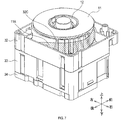
- 2A, 2B and 2C are schematic perspective views of a printing cassette in the printing apparatus of FIG. 1A.
- FIG. 3 is a schematic exploded perspective view of the printing cassette of FIG. 2A.
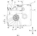
- FIG. 4 is a schematic bottom view of the printing cassette of FIG. 2A.
- FIG. 5 is a schematic cross-sectional view taken along the line VV of FIG. 6A is a schematic perspective view of a first frame portion in the printing cassette of FIG. 2A
- FIG. 6B is a schematic perspective view of a second frame portion of the printing cassette of FIG. 2A.
- FIG. 7 is a schematic perspective view showing a state in which the first case portion of the printing cassette of FIG. 2C is removed.
- FIG. 8 is a schematic view illustrating the paths of the printing tape and the ink ribbon in the printing cassette of FIG. 2A.
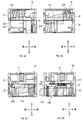
- 9A is a schematic cross-sectional view taken along the line IXA-IXA of FIG. 2C
- FIG. 9B is a schematic cross-sectional view taken along the line IXB-IXB of FIG. 2C
- FIG. 9C is a schematic cross-sectional view taken along the line IXB-IXB of FIG. 2C.
- FIG. 9D is a schematic cross-sectional view taken along the line IXC
- FIG. 9D is a schematic cross-sectional view taken along the line IXD-IXD of FIG. 2C.
- FIG. 10 is a schematic plan view of a printing apparatus main body in the printing apparatus of FIG. 1A.
- FIG. 11 is a schematic view showing an engagement state between the output gear and the platen gear in the printing apparatus of FIG. 1A.
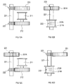
- 12A, 12B, 12C and 12D are schematic views showing the positional relationship between the drive shaft and the engaging portion of the printing apparatus in the embodiment different from that of FIG. 1A, respectively.
- the printing apparatus 1 shown in FIGS. 1A, 1B, and 1C includes a printing cassette 10 and a printing apparatus main body 100.
- the printing device 1 is a device that prints on a tape-shaped printing medium.
- the axial direction of the output gear 18 of the printing cassette 10 and the axial direction of the platen gear 104 of the printing apparatus main body 100 are the vertical directions, and the output gear 18 and the input spool 16 are aligned in the direction perpendicular to the vertical direction.
- the direction (that is, the direction in which the platen gear 104 and the drive shaft 105 are aligned) is the front-rear direction, and the direction perpendicular to both the vertical direction and the front-rear direction is the left-right direction.
- the printing apparatus main body 100 includes a cassette insertion section 101, a printing head 102, a platen roller 103, a platen gear 104, a drive shaft 105, and a housing 110.
- the cassette insertion portion 101 is a recess in which the printing cassette 10 is mounted.
- the cassette insertion unit 101 has a positioning function for the printing cassette 10.
- the cassette insertion portion 101 is provided in the housing 110.
- the print head 102 is arranged inside the cassette insertion portion 101.
- the print head 102 has a plurality of heat generating elements whose heat generation is individually controlled.
- the rotation axis L1 of the platen roller 103 is parallel to the vertical direction.
- the platen roller 103 is arranged in the vicinity of the print head 102 inside the cassette insertion portion 101.
- the platen roller 103 can swing in a direction toward or away from the print head 102.
- the platen gear 104 is connected to the platen roller 103.
- the rotation axis L2 of the platen gear 104 is arranged on the same line as the rotation axis L1 of the platen roller 103.
- the platen gear 104 can swing together with the platen roller 103.
- the drive shaft 105 is inserted into the input spool 16.
- the drive shaft 105 rotates the input spool 16.
- the drive shaft 105 is arranged inside the cassette insertion portion 101.
- the rotation axis L3 of the drive shaft 105 is parallel to the vertical direction.
- the drive shaft 105 rotates about a rotation axis L3 by a drive source (for example, a motor) (not shown).
- the print cassette 10 stores a print medium.
- the printing cassette 10 can be attached to and detached from the printing apparatus main body 100. By exchanging the printing cassette 10, the printing medium can be replenished and the type (for example, color, material, etc.) of the printing medium can be changed.
- the printing cassette 10 includes a case 35 for storing the printing tape 11A, the ink ribbon 14A (an example of the first tape), and the like.
- the outer shape of the printing cassette 10 (that is, the shape of the case 35) is a rectangular parallelepiped having a side parallel to the vertical direction, a side parallel to the front-rear direction, and a side parallel to the left-right direction.
- the case 35 has a first case portion 31, a first frame portion 32, a second frame portion 33, and a second case portion 34.
- the printing cassette 10 includes a printing tape roll 11, a first supply spool 12, spacer films 13A and 13B, an ink ribbon roll 14, a second supply spool 15, and an input spool 16.
- a spool-side spline tooth 16B (an example of a first engaging portion), a clutch spring holder 17, an output gear 18, an input gear 19, and an idle gear 20 are provided.
- the printing tape roll 11 is obtained by winding the printing tape 11A on which printing is performed around the first supply spool 12.
- the printing tape roll 11 has a cylindrical shape in which the printing tape 11A is wound around a winding center axis parallel to the vertical direction, and a hollow portion is defined by the inner peripheral surface of the wound printing tape 11A. is there.
- the printing tape roll 11 is provided with a first supply spool 12 in a hollow portion defined by the printing tape 11A. Printing is performed on the surface of the printing tape 11A by the printing head 102 of the printing apparatus main body 100 and the ink ribbon 14A.
- Two spacer films 13A and 13B are arranged on the outside of the printing tape roll 11 in the vertical direction so as to sandwich the printing tape roll 11.
- the spacer films 13A and 13B are arranged between the printing tape roll 11 and the first case portion 31 and between the printing tape roll 11 and the first frame portion 32.
- the first supply spool 12 is rotatable around the rotation axis L4.
- the first supply spool 12 rotates with the transfer of the printing tape 11A by the platen roller 103 of the printing apparatus main body 100 to supply the printing tape 11A to the printing head 102.
- the ink ribbon roll 14 is formed by winding the ink ribbon 14A used for printing the printing tape 11A around the second supply spool 15.
- the ink ribbon 14A is overlapped with the printing tape 11A at the head opening 33B and is used for printing by the printing head 102.
- the ink ribbon 14A used for printing is wound around the input spool 16.
- Rotational resistance is attached to the ink ribbon roll 14 by the clutch spring held by the clutch spring holder 17. At least a part of the ink ribbon roll 14 is arranged at a position overlapping with the printing tape roll 11 in the vertical direction.
- the second supply spool 15 is rotatable around the rotation axis L5.
- the rotation axis L5 of the second supply spool 15 is parallel to the rotation axis L4 of the first supply spool 12, that is, parallel to the vertical direction.
- the second supply spool 15 supplies the ink ribbon 14A to the print head 102 by rotating along with the winding of the ink ribbon 14A by the input spool 16.
- the input spool 16 is rotatable around the rotation axis L6.
- the rotation axis L6 of the input spool 16 is parallel to the rotation axis L5 of the second supply spool 15.
- the input spool 16 has a cylindrical shape whose hollow portion is defined by the inner peripheral surface 16A.
- the input spool 16 is a take-up spool that winds up the ink ribbon 14A. That is, the input spool 16 forms the take-up roll 14B by winding the ink ribbon 14A supplied from the ink ribbon roll 14.
- the input spool 16 is rotated by the drive shaft 105 via the spool-side spline teeth 16B.
- the take-up roll 14B has an ink ribbon 14A wound around an input spool 16 around a winding center axis parallel to the vertical direction.
- the take-up roll 14B has a cylindrical shape in which a hollow portion is defined by an inner peripheral surface.
- the spool-side spline teeth 16B are provided on the inner peripheral surface 16A of the input spool 16.
- the spool-side spline teeth 16B transmit the driving force of the drive shaft 105 of the printing apparatus main body 100 to the input spool 16.
- the spool-side spline teeth 16B project from the inner peripheral surface 16A of the input spool 16 toward the hollow portion of the input spool 16.
- the drive shaft 105 With the printing cassette 10 mounted on the printing apparatus main body 100, the drive shaft 105 is inserted into the hollow portion of the input spool 16 (that is, the take-up roll 14B), and the spool-side spline teeth 16B are engaged with the drive shaft 105. It fits. As a result, the driving force is input from the driving shaft 105 to the spool side spline teeth 16B.
- the output gear 18 is a single gear that outputs a driving force for conveying the printing tape 11A to the outside.
- the output gear 18 outputs a driving force to the platen gear 104 of the printing apparatus main body 100.
- the rotation axis L7 of the output gear 18 is parallel to the rotation axis L5 of the second supply spool 15.
- the output gear 18 overlaps the cover portion 32B in the vertical direction.
- a part of the output gear 18 is exposed at the head opening 33B.
- the output gear 18 engages with the platen gear 104 at the head opening 33B with the printing cassette 10 mounted on the printing apparatus main body 100.
- the second supply spool 15, the output gear 18, and the printing tape roll 11 are arranged side by side in the vertical direction in the order of the second supply spool 15, the output gear 18, and the printing tape roll 11. That is, the output gear 18 is located between the second supply spool 15 and the printing tape roll 11 in the vertical direction.
- the input gear 19 indirectly engages with the output gear 18 via the idle gear 20 and transmits the driving force of the drive shaft 105 to the output gear 18.
- the input gear 19 has a gear body 19A, a wall portion 19B, and a gear-side spline tooth 19C (an example of a second engaging portion).
- the gear body 19A is a single gear that engages with the idle gear 20.
- the wall portion 19B is a cylindrical spool that extends downward from a plane perpendicular to the rotation axis of the gear body 19A and has a hollow portion defined by an inner peripheral surface.
- the wall portion 19B is arranged radially inside the input gear 19 with respect to the pitch circle of the input gear 19.
- the gear side spline teeth 19C are provided on the inner peripheral surface of the wall portion 19B. That is, the gear-side spline teeth 19C are arranged radially inside the pitch circle of the input gear 19. The gear-side spline teeth 19C project toward the rotation axis L8 of the input gear 19.
- the gear-side spline teeth 19C engage with the drive shaft 105 with the printing cassette 10 mounted on the printing apparatus main body 100.
- the driving force is input from the drive shaft 105 to the gear side spline teeth 19C.
- the driving force input to the gear-side spline teeth 19C causes the gear body 19A to rotate integrally with the wall portion 19B.
- the rotation axis L8 of the input gear 19 overlaps the hollow portion of the input spool 16 (that is, the take-up roll 14B) in the vertical direction. Further, the input gear 19 is arranged so that the rotation axis L8 of the input gear 19 is on the same line as the rotation axis L6 of the input spool 16. Further, the gear body 19A of the input gear 19 is arranged at a position different from that of the input spool 16 and the take-up roll 14B in the vertical direction.
- the input spool 16, a part of the input gear 19 (that is, the gear body 19A), and the printing tape roll 11 are a part of the input spool 16 (that is, the gear body 19A) and the input gear 19 in the vertical direction.
- the printing tape roll 11 are arranged side by side in this order.
- the inscribed circle of the spool side spline teeth 16B As shown in FIG. 4, in the projection drawing in which the input spool 16 and the input gear 19 are projected onto a virtual surface perpendicular to the vertical direction (that is, the printing cassette 10 is viewed from below), the inscribed circle of the spool side spline teeth 16B.
- the diameter of the circle C1 is larger than the diameter of the inscribed circle C2 of the gear-side spline tooth 19C.
- at least a part of the gear-side spline teeth 19C overlaps with the hollow portion of the input spool 16 in the vertical direction.
- the wall portion 19B is inserted into the hollow portion of the input spool 16 (that is, the take-up roll 14B). Specifically, the lower end of the wall portion 19B is inserted into the input spool 16 to a position where it does not overlap the spool-side spline teeth 16B in the radial direction of the input spool 16.
- the drive shaft 105 is simultaneously inserted into the input spool 16 (that is, the take-up roll 14B) and the input gear 19. ..
- the spool-side spline teeth 16B and the input gear 19 are placed on the drive shaft 105 at different positions in the vertical direction. Engage.
- the input gear 19 is not directly connected to the input spool 16, but is rotated by a drive source (that is, a drive shaft 105) common to the input spool 16.
- the idle gear 20 engages the input gear 19 and the output gear 18.
- the idle gear 20 transmits the driving force input to the input gear 19 to the output gear 18.
- the rotation axis L9 of the idle gear 20 is parallel to the vertical direction.
- the idle gear 20 is a step gear in which a large gear 20A engaged with the input gear 19 and a small gear 20B engaged with the output gear 18 are arranged coaxially.
- the small gear 20B has a smaller diameter than the large gear 20A.
- the small gear 20B is arranged at a position (that is, above) closer to the printing tape roll 11 than the large gear 20A in the vertical direction.
- the idle gear 20 constitutes a reduction mechanism that reduces the rotational speed of the driving force input to the input gear 19.
- the first case portion 31 constitutes the upper end portion of the printing cassette 10.
- the first frame portion 32 is arranged below the first case portion 31 and is connected to the first case portion 31 in the vertical direction.
- the second frame portion 33 is arranged below the first frame portion 32 and is connected to the first frame portion 32 in the vertical direction.
- the second case portion 34 constitutes the lower end portion of the printing cassette 10.
- the second case portion 34 is connected to the second frame portion 33 in the vertical direction.
- the first case portion 31 and the first frame portion 32 house the printing tape roll 11. That is, the printing tape roll 11 is arranged in a space surrounded by the first case portion 31 and the first frame portion 32.
- the second case portion 34 and the second frame portion 33 house the ink ribbon roll 14, the second supply spool 15, and the input spool 16. That is, the ink ribbon roll 14, the second supply spool 15, and the input spool 16 are arranged in a space surrounded by the second case portion 34 and the second frame portion 33.
- a part of the output gear 18, the input gear 19, and the idle gear 20 are arranged in a space surrounded by the first frame portion 32 and the second frame portion 33.
- the first frame portion 32 has a first side wall portion 32A, a cover portion 32B, a first guide 32C, and a second isolation wall 32G.
- the first side wall 32A constitutes a side surface parallel to the vertical direction of the printing cassette 10.
- the cover portion 32B is a portion having a surface perpendicular to the vertical direction.
- the cover portion 32B is arranged at a position where it overlaps with the output gear 18 in the vertical direction.
- the cover portion 32B is arranged at the right front corner portion of the first frame portion 32.
- the second isolation wall 32G is arranged on the side opposite to the input spool 16 (that is, above the input gear 19) with respect to the input gear 19 in the vertical direction.
- the second isolation wall 32G isolates the input gear 19 and the printing tape roll 11 in the vertical direction.
- the second isolation wall 32G has a first gear shaft 32D, a second gear shaft 32E, a third gear shaft 32F, a gear facing surface 32H, and a support surface 32J (see FIG. 5).
- the first gear shaft 32D is inserted into the output gear 18 and rotatably supports the output gear 18.
- the second gear shaft 32E is inserted into the input gear 19 and rotatably supports the input gear 19.
- the third gear shaft 32F is inserted into the idle gear 20 and rotatably supports the idle gear 20.
- the gear facing surface 32H is a surface perpendicular to the vertical direction arranged above the output gear 18, the input gear 19, and the idle gear 20.
- the first gear shaft 32D, the second gear shaft 32E, and the third gear shaft 32F each project downward from the gear facing surface 32H.
- the support surface 32J is arranged on the side opposite to the gear facing surface 32H in the vertical direction, and supports the printing tape roll 11 from the input gear 19 side (that is, below).
- the first guide 32C is a portion around which the printing tape 11A drawn from the printing tape roll 11 is wound.
- the first guide 32C has a plurality of plate-shaped ribs arranged so as to be isolated along the circumferential direction of the printing tape roll 11.
- the plurality of ribs project in the radial direction of the printing tape roll 11, and the amount of protrusion (that is, the plate width) increases toward the lower side.
- the second frame portion 33 includes a second side wall 33A, a head opening 33B, a discharge port 33C, a second guide 33D, a first isolation wall 33E, and a hole 33F.
- the second side wall 33A constitutes a side surface parallel to the vertical direction of the printing cassette 10.
- the head opening 33B is a portion cut out from a part of the second side wall 33A.
- the head opening 33B is a space in which the print head 102 is arranged by inserting the print head 102 from below with the print cassette 10 mounted on the printing apparatus main body 100.
- the head opening 33B opens below the printing cassette 10.
- the second guide 33D is a portion around which the printing tape 11A that has passed through the first guide 32C is wound.
- the second guide 33D has a plurality of plate-shaped ribs arranged so as to be isolated along the circumferential direction of the ink ribbon roll 14. The plurality of ribs project in the radial direction of the ink ribbon roll 14, and the amount of protrusion (that is, the plate width) decreases toward the lower side.
- the first isolation wall 33E isolates the gear body 19A of the input gear 19 and the input spool 16 in the vertical direction, and supports the input gear 19 from the input spool 16 side (that is, downward).
- the first isolation wall 33E is located between the gear body 19A of the input gear 19 and the input spool 16 (that is, the take-up roll 14B) in the vertical direction, and extends in the front-rear direction and the left-right direction.
- the hole 33F is provided in the first isolation wall 33E and penetrates the first isolation wall 33E in the vertical direction.
- the hole 33F is provided at a position overlapping the gear body 19A and the second gear shaft 32E of the input gear 19 in the vertical direction.
- the wall portion 19B of the input gear 19 passes through the hole 33F and is inserted into the hollow portion of the input spool 16 (that is, the take-up roll 14B). Further, in the vertical direction, the gear body 19A of the input gear 19 is arranged between the first isolation wall 33E and the gear facing surface 32H of the second isolation wall 32G.
- the tip (that is, the lower end) of the second gear shaft 32E is arranged at a position closer to the gear facing surface 32H than the end (that is, the lower end) 19D of the wall portion 19B that is farthest from the gear facing surface 32H in the vertical direction. .. That is, the tip of the second gear shaft 32E is located above the wall portion 19B, and the second gear shaft 32E does not penetrate the wall portion 19B.
- the second gear shaft 32E has a recess 32I recessed at the tip toward the gear facing surface 32H. With the printing cassette 10 mounted on the printing apparatus main body 100, the end portion 105A of the drive shaft 105 is inserted into the recess 32I.
- the diameter of the second gear shaft 32E is smaller than the inner diameter of the wall portion 19B (that is, the diameter of the hollow portion). Further, the diameter of the end portion 105A of the drive shaft 105 is smaller than the diameter of other parts of the drive shaft 105.
- the case 35 defines a first surface 35A that defines the upper outer shell of the case 35 and a second surface that defines the lower outer shell of the case 35 at positions isolated from the first surface 35A in the vertical direction. It has a surface 35B.
- the first surface 35A and the second surface 35B intersect in the vertical direction, respectively. Further, the input spool 16 and the input gear 19 are arranged between the first surface 35A and the second surface 35B in the vertical direction.
- the first distance D1 between the end portion (that is, the upper end) of the input gear 19 on the first surface 35A side and the first surface 35A is the end portion (that is, the lower end) of the input gear 19 on the second surface 35B side. It is larger than the second distance D2 with the second surface 35B. Further, in the vertical direction, the first distance D1 is formed between the end portion (that is, the lower end) of the ink ribbon 14A (that is, the take-up roll 14B) wound around the input spool 16 on the second surface 35B side and the second surface 35B. It is larger than the third distance D3.
- the printing tape 11A and the ink ribbon 14A are bridged in the left-right direction at the head opening 33B.
- the printing tape 11A after printing is discharged to the outside of the printing device 1 from the discharge port 33C.
- a part of the output gear 18 is located in the head opening 33B. Further, the cover portion 32B is exposed in the head opening 33B.
- the first guide 32C and the second guide 33D send the printing tape 11A constituting the printing tape roll 11 from the first frame portion 32 to the second frame portion 33. It constitutes a passage.
- the printing tape 11A drawn out from the printing tape roll 11 abuts on the first guide 32C in a spiral manner from the radial outside of the printing tape roll 11. It is conveyed downward and rearward within the first frame portion 32. As shown in FIG. 9B, the printing tape 11A is further conveyed downward to the left while straddling the connecting portion between the first frame portion 32 and the second frame portion 33 in the vertical direction.
- the printing tape 11A that has reached the second frame portion 33 is conveyed downward and forward while abutting on the second guide 33D from the outside in the radial direction.
- the printing tape 11A that has reached the lower end of the printing cassette 10 passes through the head opening 33B and is discharged from the discharge port 33C.
- the print head 102 prints on the printing tape 11A held by the printing cassette 10.
- the print head 102 is arranged at a position where the printing cassette 10 is mounted on the printing apparatus main body 100 and overlaps with the printing tape 11A and the ink ribbon 14A in the front-rear direction in the head opening 33B.
- the printing tape 11A conveyed to the head opening 33B by the platen roller 103 is pressed against the printing head 102 in which the heat generating element generates heat via the ink ribbon 14A.
- a part of the ink arranged on the surface of the ink ribbon 14A is transferred to the printing tape 11A, and characters, symbols and the like are printed on the printing tape 11A.
- the platen roller 103 conveys the printing tape 11A from the inside of the printing cassette 10 to the outside.
- the platen roller 103 abuts on the printing tape 11A at the head opening 33B and presses the printing tape 11A against the printing head 102.
- the platen gear 104 is connected to the platen roller 103 and engages with the output gear 18.
- the platen roller 103 and the platen gear 104 can swing between a position isolated from the printing cassette 10 shown in FIG. 10 and a position where the platen gear 104 shown in FIG. 11 engages with the output gear 18.
- the drive shaft 105 is inserted into the input spool 16 and the input gear 19, and engages with the spool-side spline teeth 16B and the gear-side spline teeth 19C to rotate the input spool 16 and the input gear 19.
- the drive shaft 105 engages with the input gear 19 and the platen gear 104 engages with the output gear 18. Specifically, the drive shaft 105 is inserted into the input spool 16 and the input gear 19 of the printing cassette 10. After that, the platen roller 103 and the platen gear 104 are swung toward the head opening 33B of the printing cassette 10.
- the output gear 18 is rotated by rotating the input gear 19 by the drive shaft 105 with the printing cassette 10 mounted, the platen gear 104 is rotated by the rotation of the output gear 18, and the platen roller 103 is rotated by the rotation of the platen gear 104. Rotates.
- the first isolation wall 33E can appropriately maintain the positional relationship between the input gear 19 and the input spool 16 in the vertical direction. As a result, the efficiency of transmitting the driving force to the spool-side spline teeth 16B and the gear-side spline teeth 19C can be improved.
- the first engaging portion and the second engaging portion may be other than spline teeth (for example, external teeth arranged on the outer peripheral surface of the spool), respectively.
- the drive shaft does not necessarily have to be inserted into the input spool with the printing cassette mounted on the printing apparatus main body.
- the second engaging portion of the input gear may be arranged at a position that does not overlap with the hollow portion of the input spool (that is, the take-up roll) in the vertical direction.
- the wall portion is not limited to a cylindrical shape.
- the wall portion may be composed of a plurality of plate members arranged apart from each other in the circumferential direction of the input gear.
- the input gear does not necessarily have to have a wall portion, and may be a single gear that directly engages with the drive shaft.
- the direction perpendicular to the axial direction of the drive shaft 221 with respect to the input spool 211, the first engaging portion 212, and the input gear 201 ( That is, the drive shaft 221 may be inserted at a position shifted in the radial direction).
- the first engaging portion 212 is a single gear connected to the input spool 211 and engages with the first tooth 222 provided on the outer peripheral surface of the drive shaft 221. Further, the input gear 201 directly engages with the second tooth 223 provided on the outer peripheral surface of the drive shaft 221.
- a single gear having a through hole through which the drive shaft 221 is inserted may be used in the central portion.
- the input gear 201A engages with the second tooth 223 of the drive shaft 221 by spline teeth provided on the inner peripheral surface defining the through hole.
- the input spool 211A and the first engaging portion 212A of FIG. 12B correspond to the input spool 16 and the spool-side spline tooth 16B of the first embodiment, respectively.
- the first engaging portion 212A engages the first tooth 222 of the drive shaft 221.
- an input spool 211 through which the drive shaft 221 is not inserted and an input gear 201A through which the drive shaft 221 is inserted may be used.
- the input gear 201A of FIG. 12C is the same as that of FIG. 12B, and the input spool 211 and the first engaging portion 212 of FIG. 12C are the same as those of FIG. 12A.
- an input spool 211A through which the drive shaft 221 is inserted and an input gear 201 through which the drive shaft 221 is not inserted may be used.
- the input gear 201 of FIG. 12D is the same as that of FIG. 12A, and the input spool 211A and the first engaging portion 212A of FIG. 12D are the same as those of FIG. 12B.
- the printing apparatus of the above embodiment is not limited to printing using an ink ribbon.
- the printing apparatus may use a strip-shaped thermal paper as a substitute for the printing tape in the first embodiment, and may use a laminated tape (that is, a protective tape) as a substitute for the ink ribbon.
- a stencil tape in which a printing pattern is perforated by a thermal head may be used as the printing tape, and a strip-shaped interleaving paper that protects and supports the stencil tape may be used.
- the printing tape may be superimposed on the interleaving paper at a position closer to the printing head than the interleaving paper (that is, as an upper layer), and the printing tape may be separated from the interleaving paper by the printing head. It may be overlaid on the interleaving paper in position (ie, as a lower layer).
- the printing apparatus may further use a laminated tape in addition to the printing tape and the ink ribbon. That is, the printing cassette may be provided with a third supply spool that supplies the laminated tape.
- the input spool may be used as a supply spool for winding a printing tape, an ink ribbon or other tape, and supplying these tapes to the head opening. ..
- the printing cassette of the above embodiment may have two or more idle gears. Further, the idle gear does not necessarily have to be a step gear, and may be a single gear. Further, the printing cassette does not necessarily have to have an idle gear, and the output gear may be directly engaged with the input gear.
Landscapes
- Impression-Transfer Materials And Handling Thereof (AREA)
- Printers Characterized By Their Purpose (AREA)
- Unwinding Webs (AREA)
- Handling Of Continuous Sheets Of Paper (AREA)
Abstract
サイズの大型化を抑制しつつ、駆動シャフトから内部のスプールとギアとの双方に駆動力を入力できる印刷用カセットを提供する。本開示は、軸回転する駆動シャフトを備える印刷装置本体に着脱可能な印刷用カセットである。印刷用カセットは、第1テープと、第1方向と平行な回転軸心周りに回転可能であり、第1テープが巻回されている又は第1テープが巻回されるように構成されたスプールと、スプールに設けられ、駆動シャフトの駆動力をスプールに伝達する第1係合部と、第1方向においてスプールとは異なる位置に配置されると共に、他のギアと係合し、駆動シャフトの駆動力を他のギアに伝達する入力ギアと、を備える。印刷装置本体に装着された状態で、第1係合部と入力ギアとは、第1方向において互いに異なる位置で駆動シャフトに係合する。
Description
本開示は、印刷用カセットに関する。
テープに印刷を行う装置では、テープを収納したカセットを本体に着脱することで、テープの交換及び供給が行われる(特許文献1参照)。
上述のカセットは、巻取スプールを回転させることでテープを巻き取る。巻取スプールは、印刷装置の本体から駆動シャフトによって駆動力が伝達されることで回転する。また、上述のカセットにおいて、例えばテープを搬送するための駆動力を伝達するギアがカセットの内部に必要となる場合がある。このギアにも、印刷装置の本体から駆動シャフトによって駆動力を伝達する必要がある。
そのため、巻取スプール駆動用の駆動シャフトを挿入するスペースと、ギア駆動用の駆動シャフトを挿入するスペースとの双方がカセット内部に必要となる。その結果、これらの駆動シャフトの軸方向(つまり挿入方向)と垂直な方向におけるカセットのサイズが大きくなる。
本開示の一局面は、サイズの大型化を抑制しつつ、駆動シャフトから内部のスプールとギアとの双方に駆動力を入力できる印刷用カセットを提供することを目的とする。
本開示の一態様は、軸回転する駆動シャフトを備える印刷装置本体に着脱可能な印刷用カセットである。印刷用カセットは、第1テープと、第1方向と平行な回転軸心周りに回転可能であり、第1テープが巻回されている又は第1テープが巻回されるように構成されたスプールと、スプールに設けられ、駆動シャフトの駆動力をスプールに伝達する第1係合部と、第1方向においてスプールとは異なる位置に配置されると共に、他のギアと係合し、駆動シャフトの駆動力を他のギアに伝達する入力ギアと、を備える。
印刷装置本体に装着された状態で、第1係合部と入力ギアとは、第1方向において互いに異なる位置で駆動シャフトに係合する。
本開示の別の態様は、第1テープと、内周面により中空部が規定される円筒状のスプールと、内周面から中空部に向かって突出し、外部から駆動力が入力されるスプール側スプライン歯と、第1方向においてスプールとは異なる位置に配置されると共に、他のギアと係合する入力ギアと、入力ギアに設けられ、外部からの前記駆動力が入力される係合部と、を備える印刷用カセットである。
スプールは、第1方向と平行な回転軸心周りに回転可能であり、第1テープが巻回されている又は第1テープが巻回されるように構成される。係合部の少なくとも一部は、第1方向において中空部と重なる。
これらのような構成によれば、1つの駆動シャフトから、スプールの回転軸心の軸方向(つまり駆動シャフトの挿入方向)の異なる位置においてスプールと入力ギアとに駆動力を伝達することができる。そのため、駆動シャフトの挿入方向と垂直な方向における印刷用カセットのサイズの大型化を抑制しながら、スプールと入力ギアとの双方に駆動力を入力できる。
[1.第1実施形態]
[1-1.構成]
図1A,1B,1Cに示す印刷装置1は、印刷用カセット10と、印刷装置本体100とを備える。印刷装置1は、テープ状の印刷媒体に印刷を行う装置である。
[1-1.構成]
図1A,1B,1Cに示す印刷装置1は、印刷用カセット10と、印刷装置本体100とを備える。印刷装置1は、テープ状の印刷媒体に印刷を行う装置である。
本実施形態では、印刷用カセット10の出力ギア18の軸方向及び印刷装置本体100のプラテンギア104の軸方向を上下方向とし、上下方向と垂直な方向のうち出力ギア18と入力スプール16とが並ぶ方向(つまりプラテンギア104と駆動シャフト105とが並ぶ方向)を前後方向とし、上下方向と前後方向との双方に垂直な方向を左右方向とする。
<印刷装置本体>
印刷装置本体100は、カセット挿入部101と、印刷ヘッド102と、プラテンローラ103と、プラテンギア104と、駆動シャフト105と、筐体110とを備える。
印刷装置本体100は、カセット挿入部101と、印刷ヘッド102と、プラテンローラ103と、プラテンギア104と、駆動シャフト105と、筐体110とを備える。
(カセット挿入部)
カセット挿入部101は、印刷用カセット10が装着される凹部である。カセット挿入部101は、印刷用カセット10の位置決め機能を有する。カセット挿入部101は、筐体110に設けられている。
カセット挿入部101は、印刷用カセット10が装着される凹部である。カセット挿入部101は、印刷用カセット10の位置決め機能を有する。カセット挿入部101は、筐体110に設けられている。
(印刷ヘッド)
印刷ヘッド102は、カセット挿入部101の内部に配置されている。印刷ヘッド102は、個別に発熱が制御される複数の発熱素子を有する。
印刷ヘッド102は、カセット挿入部101の内部に配置されている。印刷ヘッド102は、個別に発熱が制御される複数の発熱素子を有する。
(プラテンローラ)
プラテンローラ103の回転軸心L1は、上下方向と平行である。プラテンローラ103は、カセット挿入部101の内部において、印刷ヘッド102の近傍に配置されている。プラテンローラ103は、印刷ヘッド102に対し、近づく方向又は離れる方向に揺動可能である。
プラテンローラ103の回転軸心L1は、上下方向と平行である。プラテンローラ103は、カセット挿入部101の内部において、印刷ヘッド102の近傍に配置されている。プラテンローラ103は、印刷ヘッド102に対し、近づく方向又は離れる方向に揺動可能である。
(プラテンギア)
プラテンギア104は、プラテンローラ103に連結される。本実施形態では、プラテンギア104の回転軸心L2は、プラテンローラ103の回転軸心L1と同一線上に配置されている。プラテンギア104は、プラテンローラ103と共に揺動可能である。
プラテンギア104は、プラテンローラ103に連結される。本実施形態では、プラテンギア104の回転軸心L2は、プラテンローラ103の回転軸心L1と同一線上に配置されている。プラテンギア104は、プラテンローラ103と共に揺動可能である。
(駆動シャフト)
駆動シャフト105は、入力スプール16に挿入される。駆動シャフト105は、入力スプール16を回転させる。
駆動シャフト105は、入力スプール16に挿入される。駆動シャフト105は、入力スプール16を回転させる。
駆動シャフト105は、カセット挿入部101の内部に配置されている。駆動シャフト105の回転軸心L3は、上下方向と平行である。駆動シャフト105は、図示しない駆動源(例えばモータ)によって回転軸心L3を中心に軸回転する。
<印刷用カセット>
印刷用カセット10は、印刷媒体を格納している。印刷用カセット10は、印刷装置本体100に着脱可能である。印刷用カセット10の交換により、印刷媒体の補給、及び印刷媒体の種類(例えば、色、材質等)の変更ができる。
印刷用カセット10は、印刷媒体を格納している。印刷用カセット10は、印刷装置本体100に着脱可能である。印刷用カセット10の交換により、印刷媒体の補給、及び印刷媒体の種類(例えば、色、材質等)の変更ができる。
印刷用カセット10は、図2A,2B,2Cに示すように、印刷用テープ11A、インクリボン14A(第1テープの一例)等を格納するケース35を備える。印刷用カセット10の外形(つまり、ケース35の形状)は、上下方向に平行な辺と、前後方向に平行な辺と、左右方向に平行な辺とを有する直方体状である。ケース35は、第1ケース部31と、第1枠部32と、第2枠部33と、第2ケース部34とを有する。
印刷用カセット10は、図3に示すように、印刷用テープロール11と、第1供給スプール12と、スペーサフィルム13A,13Bと、インクリボンロール14と、第2供給スプール15と、入力スプール16と、スプール側スプライン歯16B(第1係合部の一例)と、クラッチバネホルダ17と、出力ギア18と、入力ギア19と、アイドルギア20とを備える。
(印刷用テープロール)
印刷用テープロール11は、印刷が行われる印刷用テープ11Aを第1供給スプール12に巻回したものである。
印刷用テープロール11は、印刷が行われる印刷用テープ11Aを第1供給スプール12に巻回したものである。
印刷用テープロール11は、上下方向と平行な巻回中心軸を中心として印刷用テープ11Aが巻回され、巻回された印刷用テープ11Aの内周面により中空部が規定される円筒状である。
印刷用テープロール11は、印刷用テープ11Aにより規定される中空部に、第1供給スプール12が設けられている。印刷用テープ11Aの表面には、印刷装置本体100の印刷ヘッド102及びインクリボン14Aによって印刷が行われる。
印刷用テープロール11の上下方向の外側には、印刷用テープロール11を挟むように2つのスペーサフィルム13A,13Bが配置されている。スペーサフィルム13A,13Bは、印刷用テープロール11と第1ケース部31との間と、印刷用テープロール11と第1枠部32との間とに配置されている。
(第1供給スプール)
第1供給スプール12は、回転軸心L4周りに回転可能である。第1供給スプール12は、印刷装置本体100のプラテンローラ103による印刷用テープ11Aの搬送に伴って回転することで、印刷用テープ11Aを印刷ヘッド102に供給する。
第1供給スプール12は、回転軸心L4周りに回転可能である。第1供給スプール12は、印刷装置本体100のプラテンローラ103による印刷用テープ11Aの搬送に伴って回転することで、印刷用テープ11Aを印刷ヘッド102に供給する。
(インクリボンロール)
インクリボンロール14は、印刷用テープ11Aの印刷に用いられるインクリボン14Aを第2供給スプール15に巻回したものである。
インクリボンロール14は、印刷用テープ11Aの印刷に用いられるインクリボン14Aを第2供給スプール15に巻回したものである。
インクリボン14Aは、ヘッド開口33Bにおいて、印刷用テープ11Aと重ね合わされ、印刷ヘッド102による印刷に供される。印刷に使用されたインクリボン14Aは、入力スプール16に巻き取られる。
インクリボンロール14には、クラッチバネホルダ17に保持されたクラッチバネによって回転抵抗が付される。インクリボンロール14の少なくとも一部は、上下方向において、印刷用テープロール11と重なる位置に配置されている。
(第2供給スプール)
第2供給スプール15は、回転軸心L5周りに回転可能である。第2供給スプール15の回転軸心L5は、第1供給スプール12の回転軸心L4と平行、つまり上下方向と平行である。
第2供給スプール15は、回転軸心L5周りに回転可能である。第2供給スプール15の回転軸心L5は、第1供給スプール12の回転軸心L4と平行、つまり上下方向と平行である。
第2供給スプール15は、インクリボン14Aの入力スプール16による巻き取りに伴って回転することで、インクリボン14Aを印刷ヘッド102に供給する。
(入力スプール)
入力スプール16は、回転軸心L6周りに回転可能である。入力スプール16の回転軸心L6は、第2供給スプール15の回転軸心L5と平行である。
入力スプール16は、回転軸心L6周りに回転可能である。入力スプール16の回転軸心L6は、第2供給スプール15の回転軸心L5と平行である。
入力スプール16は、内周面16Aにより中空部が規定される円筒状である。入力スプール16は、インクリボン14Aを巻き取る巻取スプールである。つまり、入力スプール16は、インクリボンロール14から供給されるインクリボン14Aを巻き取ることにより、巻取ロール14Bを形成している。入力スプール16は、スプール側スプライン歯16Bを介して、駆動シャフト105によって回転される。
巻取ロール14Bは、上下方向と平行な巻回中心軸を中心として、インクリボン14Aが入力スプール16に巻回されたものである。巻取ロール14Bは、内周面により中空部が規定される円筒状である。
(スプール側スプライン歯)
スプール側スプライン歯16Bは、入力スプール16の内周面16Aに設けられている。スプール側スプライン歯16Bは、印刷装置本体100の駆動シャフト105の駆動力を入力スプール16に伝達する。
スプール側スプライン歯16Bは、入力スプール16の内周面16Aに設けられている。スプール側スプライン歯16Bは、印刷装置本体100の駆動シャフト105の駆動力を入力スプール16に伝達する。
スプール側スプライン歯16Bは、入力スプール16の内周面16Aから入力スプール16の中空部に向かって突出している。印刷用カセット10が印刷装置本体100に装着された状態で、入力スプール16(つまり巻取ロール14B)の中空部に駆動シャフト105が挿通されると共に、スプール側スプライン歯16Bが駆動シャフト105に係合する。これにより、スプール側スプライン歯16Bに駆動シャフト105から駆動力が入力される。
(出力ギア)
出力ギア18は、印刷用テープ11Aを搬送するための駆動力を外部に出力するシングルギアである。
出力ギア18は、印刷用テープ11Aを搬送するための駆動力を外部に出力するシングルギアである。
具体的には、出力ギア18は、印刷装置本体100のプラテンギア104に駆動力を出力する。出力ギア18の回転軸心L7は、第2供給スプール15の回転軸心L5と平行である。出力ギア18は、上下方向においてカバー部32Bと重なっている。
出力ギア18は、ヘッド開口33Bに一部が露出している。出力ギア18は、印刷用カセット10が印刷装置本体100に装着された状態で、ヘッド開口33Bにおいてプラテンギア104に係合する。
第2供給スプール15、出力ギア18、及び印刷用テープロール11は、上下方向において、第2供給スプール15、出力ギア18、及び印刷用テープロール11の順に並んで配置されている。つまり、出力ギア18は、上下方向において、第2供給スプール15と印刷用テープロール11との間に位置する。
(入力ギア)
入力ギア19は、アイドルギア20を介して出力ギア18と間接的に係合し、駆動シャフト105の駆動力を出力ギア18に伝達する。
入力ギア19は、アイドルギア20を介して出力ギア18と間接的に係合し、駆動シャフト105の駆動力を出力ギア18に伝達する。
入力ギア19は、ギア本体19Aと、壁部19Bと、ギア側スプライン歯19C(第2係合部の一例)とを有する。
ギア本体19Aは、アイドルギア20と係合するシングルギアである。
ギア本体19Aは、アイドルギア20と係合するシングルギアである。
壁部19Bは、ギア本体19Aの回転軸心と垂直な面から下方に延伸すると共に、内周面により中空部が規定された円筒状のスプールである。壁部19Bは、入力ギア19のピッチ円よりも入力ギア19の径方向内側に配置されている。
ギア側スプライン歯19Cは、壁部19Bの内周面に設けられている。つまり、ギア側スプライン歯19Cは、入力ギア19のピッチ円よりも径方向内側に配置されている。ギア側スプライン歯19Cは、入力ギア19の回転軸心L8に向かって突出している。
ギア側スプライン歯19Cは、印刷用カセット10が印刷装置本体100に装着された状態で、駆動シャフト105と係合する。これにより、ギア側スプライン歯19Cに駆動シャフト105から駆動力が入力される。ギア側スプライン歯19Cに入力された駆動力によって、ギア本体19Aが壁部19Bと一体回転する。
入力ギア19の回転軸心L8(つまり、ギア本体19Aの回転軸心及び壁部19Bの回転軸心)は、上下方向において入力スプール16(つまり巻取ロール14B)の中空部と重なっている。また、入力ギア19は、入力ギア19の回転軸心L8が、入力スプール16の回転軸心L6と同一線上となるように配置されている。さらに、入力ギア19のギア本体19Aは、上下方向において入力スプール16及び巻取ロール14Bとは異なる位置に配置されている。
具体的には、入力スプール16、入力ギア19の一部(つまりギア本体19A)、及び印刷用テープロール11は、上下方向において、入力スプール16の一部(つまりギア本体19A)、入力ギア19、及び印刷用テープロール11の順に並んで配置されている。
図4に示すように、入力スプール16及び入力ギア19を上下方向と垂直な仮想面に投影した投影図において(つまり、印刷用カセット10を下方から視て)、スプール側スプライン歯16Bの内接円C1の直径は、ギア側スプライン歯19Cの内接円C2の直径よりも大きい。また、ギア側スプライン歯19Cの少なくとも一部は、上下方向において、入力スプール16の中空部と重なっている。
図5に示すように、壁部19Bは、入力スプール16(つまり巻取ロール14B)の中空部に挿入されている。具体的には、入力スプール16の径方向においてスプール側スプライン歯16Bと重ならない位置まで、壁部19Bの下端部が入力スプール16に挿入されている。
入力ギア19の回転軸心L8は、上下方向において、入力スプール16の中空部と重なっているため、駆動シャフト105は入力スプール16(つまり巻取ロール14B)と入力ギア19とに同時に挿通される。
これにより、印刷用カセット10が印刷装置本体100に装着された状態で、スプール側スプライン歯16Bと入力ギア19(つまりギア側スプライン歯19C)とは、上下方向において互いに異なる位置で駆動シャフト105に係合する。その結果、入力ギア19は、入力スプール16と直接連結はされていないが、入力スプール16と共通の駆動源(つまり駆動シャフト105)によって回転される。
(アイドルギア)
アイドルギア20は、入力ギア19と出力ギア18とに係合する。アイドルギア20は、入力ギア19に入力された駆動力を出力ギア18に伝達する。アイドルギア20の回転軸心L9は、上下方向と平行である。
アイドルギア20は、入力ギア19と出力ギア18とに係合する。アイドルギア20は、入力ギア19に入力された駆動力を出力ギア18に伝達する。アイドルギア20の回転軸心L9は、上下方向と平行である。
アイドルギア20は、入力ギア19に係合した大ギア20Aと、出力ギア18に係合した小ギア20Bとが同軸上に並んで配置された段ギアである。小ギア20Bは、大ギア20Aよりも径が小さい。
また、小ギア20Bは、上下方向において、大ギア20Aよりも印刷用テープロール11に近い位置(つまり上方)に配置されている。アイドルギア20は、入力ギア19に入力された駆動力の回転速度を減速させる減速機構を構成している。
(ケース)
図3に示すように、第1ケース部31は、印刷用カセット10の上端部を構成している。第1枠部32は、第1ケース部31の下側に配置され、第1ケース部31と上下方向に連結されている。第2枠部33は、第1枠部32の下側に配置され、第1枠部32と上下方向に連結されている。第2ケース部34は、印刷用カセット10の下端部を構成している。第2ケース部34は、第2枠部33と上下方向に連結されている。
図3に示すように、第1ケース部31は、印刷用カセット10の上端部を構成している。第1枠部32は、第1ケース部31の下側に配置され、第1ケース部31と上下方向に連結されている。第2枠部33は、第1枠部32の下側に配置され、第1枠部32と上下方向に連結されている。第2ケース部34は、印刷用カセット10の下端部を構成している。第2ケース部34は、第2枠部33と上下方向に連結されている。
第1ケース部31と第1枠部32とは、印刷用テープロール11を収納している。つまり、印刷用テープロール11は、第1ケース部31と第1枠部32とで囲まれた空間に配置されている。
第2ケース部34と第2枠部33とは、インクリボンロール14、第2供給スプール15、及び入力スプール16を収納している。つまり、インクリボンロール14、第2供給スプール15、及び入力スプール16は、第2ケース部34と第2枠部33とで囲まれた空間に配置されている。
出力ギア18の一部、入力ギア19、及びアイドルギア20は、第1枠部32と第2枠部33とで囲まれた空間に配置されている。
第1枠部32は、図6Aに示すように、第1側壁32Aと、カバー部32Bと、第1ガイド32Cと、第2隔離壁32Gとを有する。
第1側壁32Aは、印刷用カセット10の上下方向と平行な側面を構成する。
第1側壁32Aは、印刷用カセット10の上下方向と平行な側面を構成する。
カバー部32Bは、上下方向と垂直な表面を有する部位である。カバー部32Bは、上下方向において出力ギア18と重なる位置に配置されている。本実施形態では、カバー部32Bは、第1枠部32の右前方の角部に配置されている。
第2隔離壁32Gは、上下方向において入力ギア19に対し入力スプール16とは反対側(つまり入力ギア19の上方)に配置されている。第2隔離壁32Gは、入力ギア19と印刷用テープロール11とを上下方向に隔離している。
第2隔離壁32Gは、第1ギア軸32Dと、第2ギア軸32Eと、第3ギア軸32Fと、ギア対向面32Hと、支持面32J(図5参照)とを有する。
第1ギア軸32Dは、出力ギア18に挿通され、出力ギア18を回転可能に支持する。第2ギア軸32Eは、入力ギア19に挿通され、入力ギア19を回転可能に支持する。第3ギア軸32Fは、アイドルギア20に挿通され、アイドルギア20を回転可能に支持する。
ギア対向面32Hは、出力ギア18、入力ギア19及びアイドルギア20の上方に配置された上下方向と垂直な面である。第1ギア軸32D、第2ギア軸32E及び第3ギア軸32Fは、それぞれ、ギア対向面32Hから下方に突出している。
支持面32Jは、上下方向においてギア対向面32Hとは反対側に配置され、印刷用テープロール11を入力ギア19側(つまり下方)から支持している。
第1ガイド32Cは、図7に示すように、印刷用テープロール11から引き出された印刷用テープ11Aが巻き掛けられる部位である。第1ガイド32Cは、印刷用テープロール11の周方向に沿って隔離して配置された複数の板状のリブを有する。複数のリブは、印刷用テープロール11の径方向に突出しており、下方に向かうほど突出量(つまり板幅)が大きくなっている。
第2枠部33は、図3及び図6Bに示すように、第2側壁33Aと、ヘッド開口33Bと、排出口33Cと、第2ガイド33Dと、第1隔離壁33Eと、孔33Fとを有する。 第2側壁33Aは、印刷用カセット10の上下方向と平行な側面を構成する。
ヘッド開口33Bは、第2側壁33Aの一部を切り欠いた部位である。ヘッド開口33Bは、印刷用カセット10が印刷装置本体100に装着された状態で、印刷ヘッド102が下方から挿入されることで、内部に印刷ヘッド102が配置される空間である。ヘッド開口33Bは、印刷用カセット10の下方に開口している。
第2ガイド33Dは、第1ガイド32Cを通過した印刷用テープ11Aが巻き掛けられる部位である。第2ガイド33Dは、第1ガイド32Cと同様に、インクリボンロール14の周方向に沿って隔離して配置された複数の板状のリブを有する。複数のリブは、インクリボンロール14の径方向に突出しており、下方に向かうほど突出量(つまり板幅)が小さくなる。
第1隔離壁33Eは、入力ギア19のギア本体19Aと入力スプール16とを上下方向に隔離すると共に、入力ギア19を入力スプール16側(つまり下方)から支持している。第1隔離壁33Eは、上下方向において入力ギア19のギア本体19Aと入力スプール16(つまり巻取ロール14B)との間に位置し、前後方向及び左右方向に延設されている。
孔33Fは、第1隔離壁33Eに設けられ、第1隔離壁33Eを上下方向に貫通している。孔33Fは、上下方向において、入力ギア19のギア本体19A及び第2ギア軸32Eと重なる位置に設けられている。
図5に示すように、入力ギア19の壁部19Bは、孔33Fを通過して入力スプール16(つまり巻取ロール14B)の中空部に挿入されている。また、上下方向において、入力ギア19のギア本体19Aは、第1隔離壁33Eと第2隔離壁32Gのギア対向面32Hとの間に配置されている。
第2ギア軸32Eの先端(つまり下端)は、上下方向において壁部19Bのうちギア対向面32Hから最も離間した端部(つまり下端)19Dよりもギア対向面32Hに近い位置に配置されている。つまり、第2ギア軸32Eの先端は、壁部19Bよりも上方に位置しており、第2ギア軸32Eは壁部19Bを貫通していない。
第2ギア軸32Eは、先端においてギア対向面32Hに向かって凹んだ凹部32Iを有する。印刷用カセット10が印刷装置本体100に装着された状態で、凹部32Iには、駆動シャフト105の端部105Aが挿入される。
なお、第2ギア軸32Eの直径は、壁部19Bの内径(つまり中空部の直径)よりも小さい。また、駆動シャフト105の端部105Aの直径は、駆動シャフト105の他の部分の直径よりも小さい。
図5に示すように、ケース35は、ケース35の上側の外郭を規定する第1面35Aと、第1面35Aと上下方向において隔離した位置でケース35の下側の外郭を規定する第2面35Bとを有する。
第1面35A及び第2面35Bは、それぞれ、上下方向と交差している。また、入力スプール16及び入力ギア19は、上下方向において第1面35Aと第2面35Bとの間に配置されている。
上下方向において、入力ギア19の第1面35A側の端部(つまり上端)と第1面35Aとの第1距離D1は、入力ギア19の第2面35B側の端部(つまり下端)と第2面35Bとの第2距離D2よりも大きい。また、上下方向において、第1距離D1は、入力スプール16に巻回されるインクリボン14A(つまり巻取ロール14B)の第2面35B側の端部(つまり下端)と第2面35Bとの第3距離D3よりも大きい。
<テープの搬送>
図8に示すように、ヘッド開口33Bにおいて、印刷用テープ11A及びインクリボン14Aが左右方向に架け渡される。印刷後の印刷用テープ11Aは、排出口33Cから印刷装置1の外部に排出される。出力ギア18の一部は、ヘッド開口33B内に位置している。また、カバー部32Bは、ヘッド開口33B内に露出している。
図8に示すように、ヘッド開口33Bにおいて、印刷用テープ11A及びインクリボン14Aが左右方向に架け渡される。印刷後の印刷用テープ11Aは、排出口33Cから印刷装置1の外部に排出される。出力ギア18の一部は、ヘッド開口33B内に位置している。また、カバー部32Bは、ヘッド開口33B内に露出している。
図9A,9B,9C,9Dに示すように、第1ガイド32C及び第2ガイド33Dは、印刷用テープロール11を構成する印刷用テープ11Aを第1枠部32から第2枠部33に送る通路を構成している。
具体的には、図9Aに示すように、印刷用テープロール11から引き出された印刷用テープ11Aは、螺旋を描くように第1ガイド32Cに印刷用テープロール11の径方向外側から当接しながら第1枠部32内で下後方に向かって搬送される。印刷用テープ11Aは、さらに図9Bに示すように、第1枠部32と第2枠部33との連結部分を上下方向に跨ぎつつ、左下方に向かって搬送される。
第2枠部33に到達した印刷用テープ11Aは、図9Cに示すように、第2ガイド33Dに径方向外側から当接しながら下前方に向かって搬送される。印刷用カセット10の下端部に到達した印刷用テープ11Aは、図9Dに示すように、ヘッド開口33Bを通過して排出口33Cから排出される。
<印刷装置本体によるテープ搬送及び印刷>
印刷ヘッド102は、印刷用カセット10が保持する印刷用テープ11Aに印刷する。 印刷ヘッド102は、印刷用カセット10が印刷装置本体100に装着された状態でヘッド開口33Bにおいて、印刷用テープ11A及びインクリボン14Aと前後方向に重なる位置に配置される。
印刷ヘッド102は、印刷用カセット10が保持する印刷用テープ11Aに印刷する。 印刷ヘッド102は、印刷用カセット10が印刷装置本体100に装着された状態でヘッド開口33Bにおいて、印刷用テープ11A及びインクリボン14Aと前後方向に重なる位置に配置される。
プラテンローラ103によってヘッド開口33Bに搬送された印刷用テープ11Aは、インクリボン14Aを介して発熱素子が発熱した印刷ヘッド102に押し付けられる。これにより、インクリボン14Aの表面に配置されたインクの一部が印刷用テープ11Aに転写され、印刷用テープ11Aに文字、記号等が印刷される。
プラテンローラ103は、印刷用テープ11Aを印刷用カセット10内から外部に向けて搬送する。プラテンローラ103は、ヘッド開口33Bにおいて印刷用テープ11Aに当接し、印刷用テープ11Aを印刷ヘッド102に押し当てる。
プラテンギア104は、プラテンローラ103に連結され、出力ギア18と係合する。プラテンローラ103及びプラテンギア104は、図10に示す印刷用カセット10と隔離した位置と、図11に示すプラテンギア104が出力ギア18に係合した位置との間で揺動可能である。
駆動シャフト105は、入力スプール16と入力ギア19とに挿入され、スプール側スプライン歯16Bとギア側スプライン歯19Cとに係合することで入力スプール16と入力ギア19とを回転させる。
図11に示すように、印刷用カセット10が印刷装置本体100に装着された状態で、駆動シャフト105が入力ギア19に係合すると共にプラテンギア104が出力ギア18に係合する。具体的には、駆動シャフト105を印刷用カセット10の入力スプール16及び入力ギア19に挿入する。その後、プラテンローラ103及びプラテンギア104を印刷用カセット10のヘッド開口33Bに向けて揺動させる。
印刷用カセット10が装着された状態で駆動シャフト105により入力ギア19が回転されることで出力ギア18が回転され、出力ギア18の回転によりプラテンギア104が回転し、プラテンギア104の回転によりプラテンローラ103が回転する。
[1-2.効果]
以上詳述した実施形態によれば、以下の効果が得られる。
(1a)1つの駆動シャフト105から、入力スプール16の回転軸心L6の軸方向(つまり駆動シャフト105の挿入方向)の異なる位置において入力スプール16と入力ギア19とに駆動力を伝達することができる。そのため、駆動シャフト105の挿入方向と垂直な方向(つまり前後方向及び左右方向)における印刷用カセット10のサイズの大型化を抑制しながら、入力スプール16と入力ギア19との双方に駆動力を入力できる。
以上詳述した実施形態によれば、以下の効果が得られる。
(1a)1つの駆動シャフト105から、入力スプール16の回転軸心L6の軸方向(つまり駆動シャフト105の挿入方向)の異なる位置において入力スプール16と入力ギア19とに駆動力を伝達することができる。そのため、駆動シャフト105の挿入方向と垂直な方向(つまり前後方向及び左右方向)における印刷用カセット10のサイズの大型化を抑制しながら、入力スプール16と入力ギア19との双方に駆動力を入力できる。
(1b)駆動シャフト105から入力スプール16へ駆動力を伝達する係合部としてスプール側スプライン歯16Bを用いることで、入力スプール16に駆動シャフト105を貫通させながら入力スプール16を回転させることができる。その結果、駆動系の配置スペースを低減することができる。
(1c)駆動シャフト105から入力ギア19へ駆動力を伝達する係合部としてギア側スプライン歯19Cを用いることで、入力スプール16と入力ギア19とを駆動シャフト105の径方向に重ねて配置することができる。その結果、駆動系の配置スペースを低減することができる。
(1d)第1隔離壁33Eによって、入力ギア19と入力スプール16との上下方向における位置関係を適切に保持することができる。その結果、スプール側スプライン歯16B及びギア側スプライン歯19Cへの駆動力の伝達効率を高めることができる。
(1e)第2ギア軸32Eが凹部32Iを有することで、駆動シャフト105の径方向における駆動シャフト105と印刷用カセット10との位置ずれを抑制することができる。その結果、スプール側スプライン歯16B及びギア側スプライン歯19Cへの駆動力の伝達効率を高めることができる。
(1f)第1距離D1が第2距離D2及び第3距離D3よりも大きいことで、印刷用カセット10が落下した際における入力ギア19の損傷を抑制することができる。
[2.他の実施形態]
以上、本開示の実施形態について説明したが、本開示は、上記実施形態に限定されることなく、種々の形態を採り得ることは言うまでもない。
以上、本開示の実施形態について説明したが、本開示は、上記実施形態に限定されることなく、種々の形態を採り得ることは言うまでもない。
(2a)上記実施形態の印刷装置において、第1係合部及び第2係合部は、それぞれ、スプライン歯以外(例えば、スプールの外周面に配置された外歯)であってもよい。また、駆動シャフトは、印刷用カセットが印刷装置本体に装着された状態で、必ずしも入力スプールに挿通されなくてもよい。
さらに、入力ギアの第2係合部は、上下方向において、入力スプール(つまり巻取ロール)の中空部と重ならない位置に配置されてもよい。また、壁部は円筒状に限定されない。例えば、壁部は、入力ギアの周方向に離間して配置された複数の板部材で構成されてもよい。さらに、入力ギアは、必ずしも壁部を有しなくてもよく、駆動シャフトに直接係合するシングルギアであってもよい。
例えば図12Aに示すように、印刷用カセットが印刷装置本体に装着されたときに、入力スプール211、第1係合部212及び入力ギア201に対し、駆動シャフト221の軸方向と直交する方向(つまり径方向)にずれた位置に駆動シャフト221が挿入されてもよい。
図12Aでは、第1係合部212は、入力スプール211に連結されたシングルギアであり、駆動シャフト221の外周面に設けられた第1歯222に係合する。また、入力ギア201は、駆動シャフト221の外周面に設けられた第2歯223に直接係合する。
また、例えば図12Bに示すように、入力ギア201Aとして、中心部に駆動シャフト221が挿通される貫通孔を有するシングルギアを用いてもよい。入力ギア201Aは、貫通孔を規定する内周面に設けられたスプライン歯によって、駆動シャフト221の第2歯223に係合する。
図12Bの入力スプール211A及び第1係合部212Aは、それぞれ、第1実施形態の入力スプール16及びスプール側スプライン歯16Bに相当する。第1係合部212Aは、駆動シャフト221の第1歯222に係合する。
さらに、例えば図12Cに示すように、駆動シャフト221が挿通されない入力スプール211と、駆動シャフト221が挿通される入力ギア201Aとを用いてもよい。図12Cの入力ギア201Aは、図12Bと同じものであり、図12Cの入力スプール211及び第1係合部212は、図12Aと同じものである。
また、例えば図12Dに示すように、駆動シャフト221が挿通される入力スプール211Aと、駆動シャフト221が挿通されない入力ギア201とを用いてもよい。図12Dの入力ギア201は、図12Aと同じものであり、図12Dの入力スプール211A及び第1係合部212Aは、図12Bと同じものである。
(2b)上記実施形態の印刷装置は、インクリボンを用いて印刷するものに限定されない。印刷装置は、第1実施形態における印刷用テープの代わりとして帯状の感熱紙を用いると共に、インクリボンの代わりとしてラミネートテープ(つまり保護テープ)を用いてもよい。
また、印刷装置は、印刷用テープとしてサーマルヘッドによって印刷パターンの穿孔が行われるステンシルテープを用いると共に、ステンシルテープを保護及び支持する帯状の合紙を用いてもよい。この場合、ヘッド開口において、印刷用テープは合紙よりも印刷ヘッドに近い位置で(つまり上層として)合紙に重ね合わせられてもよいし、印刷用テープは合紙よりも印刷ヘッドから離れた位置で(つまり下層として)合紙に重ね合わせられてもよい。
さらに、印刷装置は、印刷用テープとインクリボンとに加えて、ラミネートテープをさらに用いてもよい。つまり、印刷用カセットに、ラミネートテープを供給する第3供給スプールを設けてもよい。
(2c)上記実施形態の印刷カセットにおいて、入力スプールは、印刷用テープ、インクリボン又はそれ以外のテープが巻回され、これらのテープをヘッド開口に供給するための供給スプールとして使用されてもよい。
(2d)上記実施形態の印刷用カセットは、2つ以上のアイドルギアを有してもよい。また、アイドルギアは必ずしも段ギアでなくてもよく、シングルギアでもよい。また、印刷用カセットは、必ずしもアイドルギアを有しなくてもよく、出力ギアは直接入力ギアに係合してもよい。
(2e)上記実施形態における1つの構成要素が有する機能を複数の構成要素として分散させたり、複数の構成要素が有する機能を1つの構成要素に統合したりしてもよい。また、上記実施形態の構成の一部を省略してもよい。また、上記実施形態の構成の少なくとも一部を、他の上記実施形態の構成に対して付加、置換等してもよい。なお、特許請求の範囲に記載の文言から特定される技術思想に含まれるあらゆる態様が本開示の実施形態である。
1…印刷装置、10…印刷用カセット、11…印刷用テープロール、
11A…印刷用テープ、12…第1供給スプール、14…インクリボンロール、 14A…インクリボン、14B…巻取ロール、15…第2供給スプール、
16…入力スプール、16B…スプール側スプライン歯、18…出力ギア、
19…入力ギア、19A…ギア本体、19B…壁部、19C…ギア側スプライン歯、 20…アイドルギア、31…第1ケース部、32…第1枠部、32E…第2ギア軸、 32G…第2隔離壁、32H…ギア対向面、32I…凹部、33…第2枠部、 33E…第1隔離壁、33F…孔、34…第2ケース部、35…ケース、
100…印刷装置本体、101…カセット挿入部、102…印刷ヘッド、
103…プラテンローラ、104…プラテンギア、105…駆動シャフト。
11A…印刷用テープ、12…第1供給スプール、14…インクリボンロール、 14A…インクリボン、14B…巻取ロール、15…第2供給スプール、
16…入力スプール、16B…スプール側スプライン歯、18…出力ギア、
19…入力ギア、19A…ギア本体、19B…壁部、19C…ギア側スプライン歯、 20…アイドルギア、31…第1ケース部、32…第1枠部、32E…第2ギア軸、 32G…第2隔離壁、32H…ギア対向面、32I…凹部、33…第2枠部、 33E…第1隔離壁、33F…孔、34…第2ケース部、35…ケース、
100…印刷装置本体、101…カセット挿入部、102…印刷ヘッド、
103…プラテンローラ、104…プラテンギア、105…駆動シャフト。
Claims (12)
- 軸回転する駆動シャフトを備える印刷装置本体に着脱可能な印刷用カセットであって、 第1テープと、
第1方向と平行な回転軸心周りに回転可能であり、前記第1テープが巻回されている又は前記第1テープが巻回されるように構成されたスプールと、
前記スプールに設けられ、前記駆動シャフトの駆動力を前記スプールに伝達する第1係合部と、
前記第1方向において前記スプールとは異なる位置に配置されると共に、他のギアと係合し、前記駆動シャフトの前記駆動力を前記他のギアに伝達する入力ギアと、
を備え、
前記印刷装置本体に装着された状態で、前記第1係合部と前記入力ギアとは、前記第1方向において互いに異なる位置で前記駆動シャフトに係合する、印刷用カセット。 - 前記スプールは、内周面により中空部が規定される円筒状であり、
前記第1係合部は、前記内周面に設けられたスプール側スプライン歯であり、 前記印刷装置本体に装着された状態で、前記スプールの前記中空部に前記駆動シャフトが挿通されると共に、前記スプール側スプライン歯が前記駆動シャフトに係合する、請求項1に記載の印刷用カセット。 - 前記入力ギアは、前記入力ギアのピッチ円よりも径方向内側に配置された第2係合部を有し、
前記入力ギアの回転軸心は、前記第1方向において前記スプールの前記中空部と重なり、
前記印刷装置本体に装着された状態で、前記第2係合部が前記駆動シャフトに係合する、請求項2に記載の印刷用カセット。 - 前記入力ギアは、前記入力ギアのピッチ円よりも径方向内側に配置されると共に、前記第1方向に延伸し、前記スプールの前記中空部に挿入される壁部を有し、
前記第2係合部は、前記壁部に設けられ、前記入力ギアの前記回転軸心に向かって突出するギア側スプライン歯である、請求項3に記載の印刷用カセット。 - 第1テープと、
第1方向と平行な回転軸心周りに回転可能であり、前記第1テープが巻回されている又は前記第1テープが巻回されるように構成され、内周面により中空部が規定される円筒状のスプールと、
前記内周面から前記中空部に向かって突出し、外部から駆動力が入力されるスプール側スプライン歯と、
前記第1方向において前記スプールとは異なる位置に配置されると共に、他のギアと係合する入力ギアと、
前記入力ギアに設けられ、前記外部からの前記駆動力が入力される係合部と、 を備え、
前記係合部の少なくとも一部は、前記第1方向において前記中空部と重なる、印刷用カセット。 - 前記入力ギアの回転軸心は、前記第1方向において前記スプールの前記中空部と重なり、
前記入力ギアは、前記入力ギアのピッチ円よりも径方向内側に配置されると共に、前記第1方向に延伸し、前記スプールの前記中空部に挿入される壁部を有し、
前記係合部は、前記壁部に設けられ、前記入力ギアの前記回転軸心に向かって突出するギア側スプライン歯である、請求項5に記載の印刷用カセット。 - 前記第1方向において前記入力ギアの一部と前記スプールとの間に位置し、前記第1方向と交差する方向に延設される第1隔離壁と、
前記第1隔離壁を前記第1方向に貫通する孔と、
をさらに備え、
前記壁部は、前記孔を通過して前記スプールの前記中空部に挿入される、請求項4又は請求項6に記載の印刷用カセット。 - 前記第1方向において前記入力ギアに対し前記スプールとは反対側に配置された第2隔離壁をさらに備え、
前記第2隔離壁は、
前記入力ギアに挿通されるギア軸と、
前記ギア軸が突出するギア対向面と、
を有し、
前記第1方向において、前記入力ギアの一部は、前記第1隔離壁と前記ギア対向面との間に配置され、
前記ギア軸の先端は、前記第1方向において前記壁部のうち前記ギア対向面から最も離間した端部よりも前記ギア対向面に近い位置に配置される、請求項7に記載の印刷用カセット。 - 前記ギア軸は、前記先端において前記ギア対向面に向かって凹んだ凹部を有する、請求項8に記載の印刷用カセット。
- 前記スプール及び前記入力ギアを前記入力ギアの前記回転軸心と垂直な仮想面に投影した投影図において、前記スプール側スプライン歯の内接円の直径は、前記ギア側スプライン歯の内接円の直径よりも大きい、請求項4、又は請求項6から請求項9のいずれか1項に記載の印刷用カセット。
- 印刷用テープと、
前記第1テープが巻回された供給スプールと、
をさらに備え、
前記第1テープは、前記印刷用テープの印刷に用いられるインクリボンであり、 前記スプールは、前記インクリボンを巻き取る巻取スプールである、請求項1から請求項10のいずれか1項に記載の印刷用カセット。 - 前記スプールの少なくとも一部及び前記入力ギアの少なくとも一部が内部に配置されたケースをさらに備え、
前記ケースは、
前記ケースの外郭を規定し、前記第1方向と交差する第1面と、
前記第1面と前記第1方向において隔離した位置で前記ケースの外郭を規定し、前記第1方向と交差する第2面と、
を有し、
前記スプール及び前記入力ギアは、前記第1方向において前記第1面と前記第2面との間に配置され、
前記第1方向において、前記入力ギアの前記第1面側の端部と前記第1面との第1距離は、前記入力ギアの前記第2面側の端部と前記第2面との第2距離よりも大きく、 前記第1方向において、前記第1距離は、前記スプールに巻回される前記第1テープの前記第2面側の端部と前記第2面との第3距離よりも大きい、請求項1から請求項11のいずれか1項に記載の印刷用カセット。
Priority Applications (8)
| Application Number | Priority Date | Filing Date | Title |
|---|---|---|---|
| ES20873007T ES3010683T3 (en) | 2019-09-30 | 2020-09-15 | Printing cassette |
| PL20873007.7T PL4023453T3 (pl) | 2019-09-30 | 2020-09-15 | Kaseta drukująca |
| CN202411246563.9A CN119099234A (zh) | 2019-09-30 | 2020-09-15 | 打印用带盒 |
| EP24221711.5A EP4512626A3 (en) | 2019-09-30 | 2020-09-15 | Printing cassette |
| EP20873007.7A EP4023453B1 (en) | 2019-09-30 | 2020-09-15 | Printing cassette |
| CN202080068255.5A CN114502387B (zh) | 2019-09-30 | 2020-09-15 | 打印用带盒 |
| CN202411246570.9A CN119116563A (zh) | 2019-09-30 | 2020-09-15 | 打印用带盒 |
| US17/706,482 US20220219471A1 (en) | 2019-09-30 | 2022-03-28 | Printing cassette |
Applications Claiming Priority (2)
| Application Number | Priority Date | Filing Date | Title |
|---|---|---|---|
| JP2019-178430 | 2019-09-30 | ||
| JP2019178430A JP7322639B2 (ja) | 2019-09-30 | 2019-09-30 | 印刷用カセット |
Related Child Applications (1)
| Application Number | Title | Priority Date | Filing Date |
|---|---|---|---|
| US17/706,482 Continuation US20220219471A1 (en) | 2019-09-30 | 2022-03-28 | Printing cassette |
Publications (1)
| Publication Number | Publication Date |
|---|---|
| WO2021065466A1 true WO2021065466A1 (ja) | 2021-04-08 |
Family
ID=75271994
Family Applications (1)
| Application Number | Title | Priority Date | Filing Date |
|---|---|---|---|
| PCT/JP2020/034865 Ceased WO2021065466A1 (ja) | 2019-09-30 | 2020-09-15 | 印刷用カセット |
Country Status (7)
| Country | Link |
|---|---|
| US (1) | US20220219471A1 (ja) |
| EP (2) | EP4512626A3 (ja) |
| JP (3) | JP7322639B2 (ja) |
| CN (3) | CN119116563A (ja) |
| ES (1) | ES3010683T3 (ja) |
| PL (1) | PL4023453T3 (ja) |
| WO (1) | WO2021065466A1 (ja) |
Families Citing this family (2)
| Publication number | Priority date | Publication date | Assignee | Title |
|---|---|---|---|---|
| JP2026062315A (ja) * | 2024-09-30 | 2026-04-09 | ブラザー工業株式会社 | テープカセット |
| JP2026062310A (ja) * | 2024-09-30 | 2026-04-09 | ブラザー工業株式会社 | テープカセット |
Citations (9)
| Publication number | Priority date | Publication date | Assignee | Title |
|---|---|---|---|---|
| JPH05139006A (ja) * | 1990-11-14 | 1993-06-08 | Oki Electric Ind Co Ltd | フイルムリボンカセツト |
| JPH0582564U (ja) * | 1992-04-09 | 1993-11-09 | 三菱鉛筆株式会社 | インクリボンカセット |
| JPH0726144U (ja) * | 1993-10-20 | 1995-05-16 | マックス株式会社 | 2段式双方向インクリボンの巻き取り機構 |
| JP2000006504A (ja) * | 1998-06-24 | 2000-01-11 | Casio Comput Co Ltd | テープ巻取装置 |
| JP2006056263A (ja) | 1999-09-14 | 2006-03-02 | Brother Ind Ltd | 印字装置 |
| JP2011046142A (ja) * | 2009-08-28 | 2011-03-10 | Brother Industries Ltd | テープカセットと印字装置 |
| JP2012158175A (ja) * | 2012-03-12 | 2012-08-23 | Brother Industries Ltd | テープカセットおよびテープ印字装置 |
| JP2012236307A (ja) * | 2011-05-11 | 2012-12-06 | Fujicopian Co Ltd | 印字装置のインクリボンカセット |
| JP2015182318A (ja) * | 2014-03-24 | 2015-10-22 | セイコーエプソン株式会社 | テープカートリッジおよびテープ印刷装置 |
Family Cites Families (18)
| Publication number | Priority date | Publication date | Assignee | Title |
|---|---|---|---|---|
| US3639697A (en) * | 1969-02-28 | 1972-02-01 | Sony Corp | Magnetic tape cartridge containing engaging means for rotary head |
| IT8153179U1 (it) * | 1981-04-27 | 1982-10-27 | I P R Industrial Products Res S R L | Cartuccia a nastro per macchina per scrivere. |
| US5439303A (en) * | 1993-10-22 | 1995-08-08 | Xerox Corporation | Split-spline hub and latch mechanism |
| JP3113532B2 (ja) * | 1994-12-28 | 2000-12-04 | アルプス電気株式会社 | テープカセット |
| JPH08183230A (ja) * | 1994-12-29 | 1996-07-16 | Casio Comput Co Ltd | 印刷用カセットおよび印刷装置 |
| US6132120A (en) * | 1995-03-29 | 2000-10-17 | Brother Kogyo Kabushiki Kaisha | Tape-shaped label printing device |
| US5626306A (en) | 1995-08-11 | 1997-05-06 | Alliedsignal Inc. | Multiple level load limiter for primary and secondary collisions |
| JP3022470B2 (ja) * | 1998-03-18 | 2000-03-21 | セイコーエプソン株式会社 | テーププリンタ及びテープカセット |
| JP2005225060A (ja) * | 2004-02-12 | 2005-08-25 | Seiko Epson Corp | カートリッジ装着装置およびこれを備えたテープ印刷装置 |
| GB0417795D0 (en) * | 2004-08-10 | 2004-09-15 | Esselte Nv | Cassette locking and ejecting arrangement |
| JP2010221563A (ja) * | 2009-03-24 | 2010-10-07 | Brother Ind Ltd | テープカセット及びテープ印刷装置 |
| JP2012135931A (ja) * | 2010-12-27 | 2012-07-19 | Canon Inc | インクリボンカセット |
| CN103376696B (zh) * | 2013-07-25 | 2015-10-21 | 珠海天威飞马打印耗材有限公司 | 扭矩传输装置、激光打印机用处理盒 |
| US9884498B2 (en) * | 2014-03-24 | 2018-02-06 | Seiko Epson Corporation | Tape printing device and tape printing system |
| WO2015146095A1 (ja) * | 2014-03-24 | 2015-10-01 | セイコーエプソン株式会社 | テープ印刷装置およびテープ印刷システム |
| JP6361522B2 (ja) * | 2015-02-06 | 2018-07-25 | セイコーエプソン株式会社 | リボン送り装置およびこれを備えたテープ印刷装置 |
| JP7272030B2 (ja) * | 2019-03-19 | 2023-05-12 | セイコーエプソン株式会社 | リボン送り機構およびテープ印刷装置 |
| JP7347077B2 (ja) * | 2019-09-30 | 2023-09-20 | ブラザー工業株式会社 | 印刷用カセット |
-
2019
- 2019-09-30 JP JP2019178430A patent/JP7322639B2/ja active Active
-
2020
- 2020-09-15 CN CN202411246570.9A patent/CN119116563A/zh active Pending
- 2020-09-15 EP EP24221711.5A patent/EP4512626A3/en active Pending
- 2020-09-15 PL PL20873007.7T patent/PL4023453T3/pl unknown
- 2020-09-15 ES ES20873007T patent/ES3010683T3/es active Active
- 2020-09-15 CN CN202411246563.9A patent/CN119099234A/zh active Pending
- 2020-09-15 EP EP20873007.7A patent/EP4023453B1/en active Active
- 2020-09-15 WO PCT/JP2020/034865 patent/WO2021065466A1/ja not_active Ceased
- 2020-09-15 CN CN202080068255.5A patent/CN114502387B/zh active Active
-
2022
- 2022-03-28 US US17/706,482 patent/US20220219471A1/en active Pending
-
2023
- 2023-07-26 JP JP2023121494A patent/JP7586237B2/ja active Active
-
2024
- 2024-11-06 JP JP2024194522A patent/JP7736148B2/ja active Active
Patent Citations (9)
| Publication number | Priority date | Publication date | Assignee | Title |
|---|---|---|---|---|
| JPH05139006A (ja) * | 1990-11-14 | 1993-06-08 | Oki Electric Ind Co Ltd | フイルムリボンカセツト |
| JPH0582564U (ja) * | 1992-04-09 | 1993-11-09 | 三菱鉛筆株式会社 | インクリボンカセット |
| JPH0726144U (ja) * | 1993-10-20 | 1995-05-16 | マックス株式会社 | 2段式双方向インクリボンの巻き取り機構 |
| JP2000006504A (ja) * | 1998-06-24 | 2000-01-11 | Casio Comput Co Ltd | テープ巻取装置 |
| JP2006056263A (ja) | 1999-09-14 | 2006-03-02 | Brother Ind Ltd | 印字装置 |
| JP2011046142A (ja) * | 2009-08-28 | 2011-03-10 | Brother Industries Ltd | テープカセットと印字装置 |
| JP2012236307A (ja) * | 2011-05-11 | 2012-12-06 | Fujicopian Co Ltd | 印字装置のインクリボンカセット |
| JP2012158175A (ja) * | 2012-03-12 | 2012-08-23 | Brother Industries Ltd | テープカセットおよびテープ印字装置 |
| JP2015182318A (ja) * | 2014-03-24 | 2015-10-22 | セイコーエプソン株式会社 | テープカートリッジおよびテープ印刷装置 |
Non-Patent Citations (1)
| Title |
|---|
| See also references of EP4023453A4 |
Also Published As
| Publication number | Publication date |
|---|---|
| EP4023453C0 (en) | 2025-01-29 |
| EP4512626A2 (en) | 2025-02-26 |
| JP2025013535A (ja) | 2025-01-24 |
| JP7586237B2 (ja) | 2024-11-19 |
| JP2023138563A (ja) | 2023-10-02 |
| US20220219471A1 (en) | 2022-07-14 |
| PL4023453T3 (pl) | 2025-06-09 |
| CN119116563A (zh) | 2024-12-13 |
| CN114502387A (zh) | 2022-05-13 |
| CN119099234A (zh) | 2024-12-10 |
| CN114502387B (zh) | 2024-09-24 |
| ES3010683T3 (en) | 2025-04-04 |
| EP4023453A4 (en) | 2023-09-13 |
| JP7736148B2 (ja) | 2025-09-09 |
| JP2021053893A (ja) | 2021-04-08 |
| EP4512626A3 (en) | 2025-04-30 |
| EP4023453A1 (en) | 2022-07-06 |
| JP7322639B2 (ja) | 2023-08-08 |
| EP4023453B1 (en) | 2025-01-29 |
Similar Documents
| Publication | Publication Date | Title |
|---|---|---|
| JP7736148B2 (ja) | 印刷用カセット | |
| JP7529100B2 (ja) | カセット | |
| JP7322640B2 (ja) | 印刷用カセット | |
| JP7736139B2 (ja) | 印刷用カセット | |
| JP7593152B2 (ja) | 補助テープカセット、印刷用テープカセット及び印刷用カセット | |
| JP7528689B2 (ja) | 印刷用カセット及び印刷装置 | |
| WO2021065472A1 (ja) | 印刷装置及び印刷用カセット | |
| WO2021065473A1 (ja) | 印刷用カセット | |
| JP2021053916A (ja) | 印刷装置及び印刷用カセット |
Legal Events
| Date | Code | Title | Description |
|---|---|---|---|
| 121 | Ep: the epo has been informed by wipo that ep was designated in this application |
Ref document number: 20873007 Country of ref document: EP Kind code of ref document: A1 |
|
| NENP | Non-entry into the national phase |
Ref country code: DE |
|
| ENP | Entry into the national phase |
Ref document number: 2020873007 Country of ref document: EP Effective date: 20220328 |