WO2021065896A1 - Outil médical et ensemble d'outils médicaux - Google Patents
Outil médical et ensemble d'outils médicaux Download PDFInfo
- Publication number
- WO2021065896A1 WO2021065896A1 PCT/JP2020/036860 JP2020036860W WO2021065896A1 WO 2021065896 A1 WO2021065896 A1 WO 2021065896A1 JP 2020036860 W JP2020036860 W JP 2020036860W WO 2021065896 A1 WO2021065896 A1 WO 2021065896A1
- Authority
- WO
- WIPO (PCT)
- Prior art keywords
- medical device
- end portion
- fusion promoting
- fusion
- curved surface
- Prior art date
- Legal status (The legal status is an assumption and is not a legal conclusion. Google has not performed a legal analysis and makes no representation as to the accuracy of the status listed.)
- Ceased
Links
Images


Classifications
-
- A—HUMAN NECESSITIES
- A61—MEDICAL OR VETERINARY SCIENCE; HYGIENE
- A61B—DIAGNOSIS; SURGERY; IDENTIFICATION
- A61B17/00—Surgical instruments, devices or methods
- A61B17/11—Surgical instruments, devices or methods for performing anastomosis; Buttons for anastomosis
Definitions
- the present invention relates to a medical device and a medical device set.
- Various methods and medical instruments are used in the technique of joining living organs.
- a method of suturing a living organ with a biodegradable suture or a mechanical anastomosis device for anastomosis with a stapler see Patent Document 1.
- the method of using is proposed.
- the joint force between biological organs at the joint can be increased as compared with the method using sutures, which reduces the risk of suture failure. Will be possible.
- the degree of progression of fusion at the junction also depends on the condition of the biological tissue at the junction target site (joint site) of the patient. Therefore, for example, even when a joining device as described in Patent Document 1 is used, the risk of suture failure may not be sufficiently reduced depending on the condition of the patient's living tissue.
- an object of the present invention is to provide a fusion promoting device capable of reducing the risk of suture failure after surgery or the like.
- One aspect of the present invention is a medical device including a deployable portion.
- the unfolded portion includes a curved surface including a first end portion and a second end portion provided on the side opposite to the first end portion, and is a living tissue when the first end portion and the second end portion are brought into contact with each other. It is configured to be able to form a semi-closed space that can surround the fusion promoting device that promotes fusion.
- a medical device set having the above medical device and a fusion promoting device.
- the risk of suture failure after surgery or the like can be reduced.
- FIG. 3 is a perspective view showing a tip of a first engaging instrument and a second engaging instrument constituting the medical device according to FIG. 1. It is a perspective view which shows the state which the fusion promotion device is inserted through the shaft of the 2nd engaging device which constitutes a medical device. It is a side view of FIG. It is sectional drawing which shows the through hole in the fusion promotion device of FIG. It is a perspective view which shows the state which surrounded the fusion promotion device with the medical device shown in FIG. It is a perspective view which shows the medical instrument. It is a perspective view which shows the developed state of the medical device shown in FIG. 7.
- FIG. 1 It is sectional drawing which shows the positioning part which comprises the medical device. It is a flowchart which shows each procedure of the treatment method using a fusion promotion device. It is a flowchart which shows the procedure of embodiment (colon anastomosis) of a treatment method. It is a schematic cross-sectional perspective view for demonstrating colorectal anastomosis. It is a figure which shows the vicinity of the abdomen (around the navel) of a patient in which a fusion promotion device is placed. It is a schematic cross-sectional view for demonstrating colorectal anastomosis. It is a schematic side view for demonstrating colorectal anastomosis.
- ⁇ First Embodiment> 1 to 9 are diagrams provided for explaining the fusion promoting device 100 and the medical device 400 according to the first embodiment of the present invention.
- 10 to 16 are views for explaining the case of performing gastrointestinal anastomosis using the large intestine as an example using the fusion promoting device 100.
- the fusion promoting device 100 and the medical device 400 can be collectively referred to as the medical device set 1.
- the fusion promoting device 100 can be applied to a procedure for joining predetermined biological organs (for example, gastrointestinal anastomosis) as shown in FIGS. 12 to 16.
- predetermined biological organs for example, gastrointestinal anastomosis
- FIGS. 12 to 16 As will be described later, in the description of the present specification, the large intestine anastomosis technique will be described as an example of the procedure using the fusion promoting device 100, but the site where the fusion promoting device according to the present invention can be used is not limited to the large intestine.
- the fusion promoting device 100 is used when the first jointed portion such as the large intestine and the second joined portion are joined by the medical device 200.
- the medical device 200 will be described in the description of the medical device set 1.
- the medical device 200 joins a first jointed portion in a living tissue and a second joined portion facing the first joined portion.
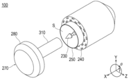
- the medical device 200 includes a first engaging device 210 and a second engaging device 270 capable of sandwiching the main body portion 10 through the first joined portion and the second joined portion.
- the first engaging instrument 210 can be brought into contact with the first joined portion, and the second engaging instrument 270 is configured to be able to come into contact with the second joined portion. Details will be described later.
- the first engaging device 210 may be referred to as a trocar and the second engaging device 270 may be referred to as an anvil.
- the first engaging instrument 210 includes a long member 220, a positioning portion 230, a discharging portion 240, a punching portion 250, and an operating portion 260.
- the long member 220 corresponds to the main body of the first engaging device 210. As shown in FIG. 2, the long member 220 includes a space S in which the shaft of the positioning portion 230 can be relatively moved back and forth at the tip in the longitudinal direction.
- the longitudinal direction at the tip of the long member 220 is defined as the direction X.
- the long member 220 has a hollow circular cross section intersecting the direction X.
- the long member 220 extends linearly in the longitudinal direction and has a bent portion. However, if the anastomosis function and the punching function described later can be realized, the long member does not have a bent portion. May be good.
- the positioning unit 230 includes a long shaft. As shown in FIG. 2, the shaft of the positioning portion 230 is configured to be relatively movable back and forth from the space S at the tip of the long member 220 in the longitudinal direction.
- the discharge unit 240 is configured to be capable of releasing a plurality of staples that join the first bonded portion and the second bonded portion.
- the discharge portion 240 is formed in a substantially disk shape on the tip end side in the longitudinal direction of the long member 220.
- the discharge portion 240 is configured by providing a plurality of staple discharge points along the circumferential direction ⁇ at the tip of the long member 220.
- the plane direction intersecting the longitudinal direction at the tip of the long member 220 is defined as the direction YZ
- the radial direction or the radial direction is defined as the radial direction r
- the circumferential direction or the angular direction is defined as the circumferential direction ⁇ .
- the punching portion 250 is arranged at the tip of the long member 220 inward in the radial direction r than the discharging portion 240, and is configured to punch inward in the radial direction of the first bonded portion and the second bonded portion. ing. As shown in FIG. 2, the punching portion 250 is configured to include an annular blade that punches the first bonded portion and the second bonded portion inward in the radial direction r than the discharging portion 240.
- the shape of the punched portion 250 can be formed into a perfect circle when viewed in a plan view from the longitudinal direction, but the shape of the punched portion 250 may be an ellipse or the like in addition to the above as long as the portion unnecessary for promoting fusion is punched out.
- the operation unit 260 is configured so that the positioning unit 230, the discharge unit 240, and the punching unit 250 can be operated.
- the operation unit 260 includes a rotating unit 261 and a handle 262.
- the rotating portion 261 is provided at the proximal end portion (base end side) of the long member 220 in the longitudinal direction.
- the rotating portion 261 is configured to be rotatable with respect to the long member 220 with the longitudinal direction on the base end side of the long member 220 as the rotation axis.
- the rotating portion 261 is rotated with respect to the long member 220 to form the first engaging tool 210 and the second engaging tool 270. Is configured so that they can be relatively close and separated.
- the handle 262 is configured to be grippable by the user together with the base end portion (base end side) of the long member 220.
- the handle 262 is rotatably connected to the elongated member 220 by a rotating shaft 263.
- the handle 262 rotates around the rotating shaft 263 and comes relatively close to the elongated member 220 when gripped by the user. As a result, the staples are discharged from the discharging portion 240, and the annular blade of the punching portion 250 can be projected from the tip of the long member 220.
- the second engaging device 270 is configured so that the main body 10 of the fusion promoting device 100 can be sandwiched between the first joined portion and the second joined portion.
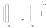
- the second engaging device 270 includes a head 280, a contact portion 290, and a shaft 310 as shown in FIGS. 3 and 4.
- the head 280 is arranged adjacent to the long member 220 of the first engaging device 210, particularly on the tip end side, when the first engaging device 210 and the second engaging device 270 are engaged with each other.
- the head 280 is configured to have a substantially disk shape as shown in FIGS. 2 and 3, and the cross-sectional shape is configured to be the same as or similar to the circular shape of the long member 220.
- the contact portion 290 is configured to be able to contact a plurality of staples discharged from the discharge portion 240.
- the contact portion 290 is provided on the side of the first engaging device 210 in the axial direction of the head 280 (the plate thickness direction, see the direction X in FIG. 3).
- the contact portion 290 is configured so as to be able to contact a plurality of staples discharged from the discharge portion 240.
- the staples released from the discharging portion 240 are brought into contact with each other at the contacting portion 290 and deformed to join the first bonded portion and the second bonded portion.
- the shaft 310 is configured to be engageable with the shaft of the positioning portion 230, and is provided for engaging the first engaging instrument 210 and the second engaging instrument 270.
- the shaft 310 is configured to extend axially from the side of the first engaging device 210 in the axial direction (direction X) of the head 280.
- the shaft 310 has a circular cross section perpendicular to the longitudinal direction in the present embodiment.
- the shaft 310 is provided with a space for accommodating the shaft of the positioning portion 230 of the first engaging device 210.
- the shaft 310 is configured to fit the shaft of the positioning portion 230, which enables the alignment of the first engaging instrument 210 and the second engaging instrument 270.
- the fusion promoting device 100 includes a main body portion 10, a reinforcing portion 20, and a hole portion 30.
- the main body portion 10 is formed in a sheet shape, and promotes fusion of the living tissue when joining the first joined portion in the living tissue and the second joined portion facing the first joined portion.
- the main body portion 10 is formed in a circular shape as an example, and includes a plurality of through holes 11 formed so as to be inserted in the thickness direction (direction X) of the circular shape.
- the size of the through hole 11 of the main body 10 is preferably 0.1 to 6 mm, more preferably 0.3 to 4 mm, and further preferably 0.6 to 1.5 mm.
- the main body 10 can be configured such that the ratio of the dimension D of the through hole 11 to the pitch P is 0.25 or more and less than 40.
- the main body 10 can be made of a biodegradable material.
- the constituent material of the main body 10 is not particularly limited, and examples thereof include biodegradable resins.
- polystyrene resin is selected from the group consisting of (1) aliphatic polyester, polyester, polyacid anhydride, polyorthoester, polycarbonate, polyphosphazene, polyphosphate ester, polyvinyl alcohol, polypeptide, polysaccharide, protein, and cellulose.
- Polymer (2) A copolymer composed of one or more monomers constituting the above (1) and the like can be mentioned.
- the biodegradable sheet is selected from the group consisting of aliphatic polyesters, polyesters, polyacid anhydrides, polyorthoesters, polycarbonates, polyphosphazenes, polyphosphates, polyvinyl alcohols, polypeptides, polysaccharides, proteins, and celluloses. It preferably contains at least one biodegradable resin selected from the group consisting of a polymer and a copolymer composed of one or more monomers constituting the polymer.
- the reinforcing portion 20 is used to suppress twisting, misalignment, breakage, etc. of the fusion promoting device 100 when the fusion promoting device 100 is placed between the first bonded portion and the second bonded portion by the medical device 200.
- the reinforcing portion 20 includes an inner reinforcing portion 21 and an outer reinforcing portion 22.
- the inner reinforcing portion 21 is formed along the inner peripheral edge in the hollow circular shape of the main body portion 10
- the outer reinforcing portion 22 is formed along the outer peripheral edge in the hollow circular shape of the main body portion 10.
- the inner reinforcing portion 21 and the outer reinforcing portion 22 are configured so as not to have a through hole 11 in the main body portion 10.
- the specific shape of the reinforcing portion 20 is not limited to the above, and the position may not be the inner peripheral edge or the outer peripheral edge as long as the twisting or shifting of the fusion promoting device 100 can be prevented or suppressed and the strength can be improved.
- the hole 30 is configured to be insertable into the shaft 310 of the medical device 200 when anastomosing biological tissue via the fusion promoting device 100 using a medical device 200 including a second engaging device 270 with a shaft 310. doing.
- the hole portion 30 has a substantially circular shape when viewed from the axial direction in the present embodiment.
- fibers containing the above-mentioned biodegradable material are arranged in a circumferential shape in the portion of the through hole 11 of the main body 10, and similar fibers are arranged in the radial direction to make a circumference.
- a method is conceivable in which the shaped fibers and the fibers in the radial direction are woven together.
- the method for producing the fiber made of biodegradable resin include an electrospinning method (electrospinning method / electrostatic spinning method) and a melt blow method.
- electrospinning method electrospinning method / electrostatic spinning method
- melt blow method for the main body 10 only one of the above methods may be selected, or two or more thereof may be appropriately combined.
- the main body 10 induces a biological reaction by a constituent material such as a biodegradable resin constituting the main body 10.
- the main body 10 induces the expression of biological components such as fibrin by this action.
- the biological components induced in this way can promote fusion by accumulating so as to penetrate through the through hole 11 of the main body 10. Therefore, by arranging the main body 10 of the fusion promoting device 100 between the biological organs to be joined, the fusion is promoted by the above mechanism.
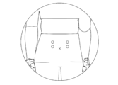
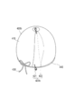
- the medical device 400 is configured to be able to surround the fusion promoting device 100 that promotes the fusion of living tissues. As shown in FIG. 6 and the like, the medical device 400 includes a deploying portion 410, a connecting portion 420, a regulating member 430, and a positioning portion 440.
- the unfolding portion 410 includes a curved surface 411, a first end portion 412, a second end portion 413, openings 414, 415, and a semi-closed space 416.
- the curved surface 411 includes a first end portion 412 and a second end portion 413, and is configured to form a part of a hollow sphere in the present embodiment.
- the curved surface 411 is made transparent like vinyl so that the state of the fusion promoting device 100 arranged inside can be easily visually recognized.
- the curved surface 411 is configured to be expandable by providing a first end portion 412 and a second end portion 413.
- the first end portion 412 and the second end portion 413 can be configured like a generatrix forming a spherical surface as an example.
- the second end portion 413 is located on the opposite side of the developed curved surface 411 from the first end portion 412 as shown in FIG.
- the curved surface 411 forms a semi-closed space 416 capable of surrounding the fusion promoting device 100 when the first end portion 412 and the second end portion 413 are brought into contact with each other.
- the curved surface 411 can be configured such that the first end portion 412 partially forms a spherical surface when the first end portion 412 and the second end portion 413 are overlapped with each other, but the curved surface 411 may be irregular or irregular depending on the material. It may have a non-regular shape.
- the first end portion 412 and the second end portion 413 are configured as end portions when the spherical surface is unfolded.
- the first end portion 412 and the second end portion 413 are strip-shaped rather than extremely small regions such as linear. It is preferable to configure it as an area where a certain degree of area can be conceived.
- a member such as a cover cloth or the like is used. May be provided.
- the openings 414 and 415 are formed on a substantially hemispherical curved surface 411 when the fusion promoting device 100 is surrounded by the medical device 400.
- the openings 414 and 415 correspond to a portion where the semi-closed space 416 communicates with the outside in a state where the first end portion 412 and the second end portion 413 are in contact with each other.
- the openings 414 and 415 are formed like a cut portion when a hollow spherical shape is cut, and the opening 414 has a shorter peripheral length than the opening 415 in the present embodiment.
- the opening 414 can fix the medical device 400 together with the fusion promoting device 100 to the living tissue in a state of surrounding the fusion promoting device 100 by shortening the peripheral length of the opening by the regulating member 430 described later.
- the semi-closed space 416 is formed radially inward from the curved surface 411 in a state where the first end portion 412 and the second end portion 413 are overlapped with each other.
- the semi-closed space 416 communicates with the outside through openings 414 and 415.
- the connecting portion 420 is configured to connect the first end portion 412 and the second end portion 413 in a state where the semi-closed space 416 is formed by the curved surface 411.
- the connecting portion 420 is configured separately from the deploying portion 410 in the present embodiment.
- the connecting portion 420 is a thread or the like capable of suturing the first end portion 412 and the second end portion 413 of the curved surface 411 in a state where the first end portion 412 and the second end portion 413 are in contact with each other. It can be configured to include one long member.
- the regulating member 430 is configured to regulate the size of the opening 414. Thereby, the medical device 400 can be fixed to the living tissue together with the fusion promoting device 100 in a state where the fusion promoting device 100 is surrounded by the medical device 400.
- the regulating member 430 is preferably a long member such as the first long member of the connecting portion 420, and more preferably a wide and stretchable member such as a vessel tape can be used.
- the regulating member 430 is configured to include a second long member arranged along the edge of the opening 414 in the unfolding portion 410 in the present embodiment. As an example, the regulating member 430 can regulate the curved surface 411 of the deploying portion 410 so that the inner diameter is smaller than the outer diameter of the head 280 of the second engaging device 270 of the medical device 200 or the biological tissue such as the intestinal tract.
- the positioning portion 440 is provided to position the regulating member 430 in the vicinity of the opening 414 of the curved surface 411.
- the positioning portion 440 can be formed so as to cover the regulating member 430 together with the curved surface 411 at a part of the edge portion of the opening 414 of the developing portion 410 as shown in FIG.
- a treatment method using the fusion promoting device 100 will be described.
- 10 and 11 are flowcharts showing each procedure of the treatment method using the fusion promoting device 100.
- 12 to 16 are schematic views for explaining colorectal anastomosis.
- a sheet-shaped main body portion 10 that promotes fusion of living tissues between one first joined site and the other second joined site, which are the objects to be joined of living organs, is formed. It includes arranging the fusion promoting device 100 to be provided (S11). The treatment method is that at least a part of the main body 10 of the fusion promoting device 100 is arranged between one first joined site and the other second joined site, and one first joined site and the other It includes joining with the second jointed portion (S12).
- the living organ to be joined by the treatment method and the joining site in the living organ are not particularly limited and can be arbitrarily selected.
- colon anastomosis will be described as an example.
- arranging a fusion promoting device between living organs means that the healing promoting device is in direct or indirect contact with the living organ. It can mean that it is placed.
- the above description may mean that the fusion promoting device is arranged in a state where a spatial gap is formed between the living organ and the living organ. Further, in the above description, the fusion promoting device is arranged in both states (for example, the fusion promoting device is in contact with one biological organ and the fusion promoting device is not in contact with the other biological organ). To be done) can mean.
- peripheral does not define a strict range (region), but a predetermined range (region) as long as the purpose of treatment (bonding between biological organs) can be achieved. Means.
- the biological organ to be joined is the large intestine that has been cut due to the excision of the cancer tumor.
- the biological organs to be joined are the oral side A2 of the cut large intestine and the anal side A1 of the cut large intestine.
- the procedure for joining the area around the mouth of the mouth side A2 of the cut large intestine (second joint site) and a part of the intestinal wall of the anal side A1 of the cut large intestine (first joint site) will be described. explain.
- the treatment method according to the present embodiment is to dispose the fusion promoting device 100 between the mouth of the large intestine and the intestinal wall of the large intestine (S101), the mouth of the large intestine and the intestine of the large intestine. Includes making the walls relatively close (S102).
- the treatment method is to sandwich the main body 10 of the fusion promoting device 100 between the periphery of the mouth of the large intestine and the intestinal wall of the large intestine (S103), and the fusion promoting device between the periphery of the mouth of the large intestine and the intestinal wall of the large intestine. This includes joining (S104) with the main body 10 sandwiched between 100. The details will be described below.
- the surgeon forms a hole-like part called a port around the navel (the part indicated by ⁇ in FIG. 13) in FIG. 13 to inflate the patient's abdomen.
- a port around the navel the part indicated by ⁇ in FIG. 13
- two ports indicated by ⁇ are formed on the left and right sides of the navel, but the positions and numbers of the ports are merely examples and are not limited to FIG.
- the operator makes an incision around the navel indicated by x in FIG. 13, and takes out the affected part of the oral side A2 from the incision. Then, the surgeon cuts out the affected part to be operated through the port.
- the operator inserts the second engaging instrument 270 of the medical device 200 into the oral side A2 of the large intestine.
- the operator inserts the shaft 310 of the second engaging instrument 270 into the oral side A2 of the large intestine, and draws a purse stitch with the shaft 310 protruding to form the sutured portion A21.
- the outer surface of the sewn portion A21 has a shape that partially protrudes to the convex side as the sewn portion A21 is sewn.
- the operator places the fusion promoting device 100 on the oral side A2 of the large intestine (S101).
- the operator passes the shaft 310 included in the second engaging instrument 270 through the hole 30 formed in the main body 10 as shown in FIG.
- the main body 10 is deformed so that the inside of the main body 10 in the radial direction r is raised as shown in FIG. 14 according to the shape of the sutured portion A21 formed so as to be raised in the living body.
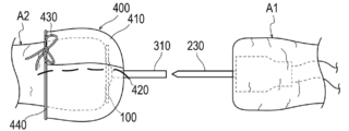
- the surgeon surrounds the fusion promoting device 100 placed on the oral side A2 of the large intestine with the medical device 400 as shown in FIG.
- the medical device 400 as an initial state in the present embodiment, a long member related to the connecting portion 420 is sutured to the deploying portion 410, and a knot is not formed in a state where the regulating member 430 is arranged in the positioning portion 440. It has become.
- the medical device 400 is configured to form a substantially hemispherical shape by the connecting portion 420 in a state where the first end portion 412 and the second end portion 413 overlap each other.
- the surgeon covers the biological tissue on which the fusion promoting device 100 is arranged with a substantially hemispherical curved surface 411, and surrounds the healing promoting device 100 together with a part of the biological tissue by the medical device 400. Then, the opening 414 is tied with the regulating member 430 and a knot is formed to shorten the peripheral length of the opening 414, and the fusion promoting device 100 is fixed so as not to fall off from the living tissue.
- the operator accommodates the biological tissue on the oral side A2 including the fusion promoting device 100 and the medical device 400 from the incision indicated by x in FIG. 13 into the body.
- the operator places the first engaging device 210 of the medical device 200 on the anal side A1 of the large intestine.
- a through hole A11 is formed in the anal side A1 of the large intestine.
- the rotating portion 261 is rotated so that the first engaging tool 210 and the second engaging tool 270 are relatively close to each other.
- the periphery of the mouth of the large intestine and the intestinal wall of the large intestine are relatively close to each other (S102).
- the surgeon unties the knot by the regulating member 430 immediately before sandwiching the fusion promoting device 100 between the first engaging instrument 210 and the second engaging instrument 270, and pulls the connecting portion 420 from the deploying portion 410. Remove.
- the curved surface 411 can be expanded.
- the order of unwinding the regulating member 430 and removing the connecting portion 420 may be reversed.
- the curved surface 411 is developed using forceps or the like, and the medical device 400 is removed from the fusion promoting device 100 and the biological organ.
- the removed medical device 400 is taken out of the body through a port formed near the patient's abdomen.
- connection portion 420 which is separate from the medical device 400 at this point, is also taken out of the body.
- surgeon between the first engaging instrument 210 and the second engaging instrument 270, is located around the mouth of the oral side A2 of the large intestine, the main body 10 of the fusion promoting device 100, and the anal side A1 of the large intestine.
- the periphery of the through hole A11 formed in the intestinal wall is sandwiched (S103).
- the surgeon grasps the handle 262 of the operation unit 260 of the medical device 200, that is, rotates the handle 262 around the rotation shaft 263 to bring it closer to the rotation portion 261 and causes the annular blade of the punching portion 250 to protrude. ..
- a part of the oral side A2 of the large intestine, the main body 10 and a part of the anal side A1 of the large intestine sandwiched between the first engaging device 210 and the second engaging device 270 were excised and excised.
- the periphery of the portion is joined by staples (not shown) (S104).
- the surgeon takes out the medical device 200 from, for example, the anal side A1 of the large intestine to the outside of the living body via the anus.
- the region formed inward from the outer diameter of the punched portion 250 of the first engaging device 210 is taken out of the living body together with the medical device 200.
- the portion located inward in the radial direction r than the punched portion 250 does not remain in the body and is removed.
- a joining technique for example, gastrointestinal anastomosis
- a simple method of sandwiching the sheet-shaped main body portion 10 between the first joined portion and the second joined portion is performed by a simple method of sandwiching the sheet-shaped main body portion 10 between the first joined portion and the second joined portion. The risk of subsequent suture failure can be reduced.
- the medical device 400 constituting the medical device set 1 according to the present embodiment has a deploying unit 410.
- the unfolding portion 410 includes a curved surface 411 including a first end portion 412 and a second end portion 413 provided on the opposite side of the first end portion 412.
- the unfolding portion 410 is configured to be able to form a semi-closed space 416 capable of surrounding the fusion promoting device 100 that promotes the fusion of living tissues when the first end portion 412 and the second end portion 413 are brought into contact with each other. ..
- the fusion promoting device 100 can be maintained in a state of being surrounded by the deploying unit 410 until immediately before the fusion promoting device 100 is placed in the living body. Therefore, it is possible to prevent or suppress foreign matter from adhering to the fusion promoting device 100. As described above, according to the medical device set 1, it is possible to prevent or suppress the adhesion of foreign matter to the fusion promoting device 100, and reduce the risk of suture failure after surgery or the like.
- the medical device 400 includes a connection portion 420.
- the connecting portion 420 is configured to connect the first end portion 412 and the second end portion 413 in a state where the semi-closed space 416 is formed by the curved surface 411. With this configuration, the curved surface 411 of the unfolding portion 410 can be maintained in an unexpanded state, and foreign matter can be prevented or suppressed from adhering to the fusion promoting device 100.
- the connecting portion 420 is configured to include a first long member that can be sewn in a state where the first end portion 412 and the second end portion 413 are in contact with each other. Therefore, the connection by the first long member can be released only by unsewn, and the procedure can proceed smoothly.
- the unfolding portion 410 includes an opening 414 in which the semi-closed space 416 communicates with the outside in a state where the first end portion 412 and the second end portion 413 are in contact with each other.
- the medical device 400 is configured to have a regulatory member 430 that regulates the size of the opening 414.
- the medical device 400 can be fixed to the living tissue together with the fusion promoting device 100 in a state where the fusion promoting device 100 is surrounded by the deploying portion 410, and foreign matter can be prevented or suppressed from adhering to the fusion promoting device 100.
- the regulation member 430 can include a second long member arranged along the edge of the opening 414.
- the medical device 400 can be fixed to or released from the living tissue by an operation such as tying or unwinding the second long member near the edge of the opening 414.
- the regulating member 430 at the edge of the opening 414 in the developing portion 410, it is possible to prevent or suppress the fusion promoting device 100 from being twisted or displaced with respect to the living tissue inside the medical device 400.
- the opening 415 is configured to be provided with a positioning portion 440 for positioning the regulation member 430.
- FIG. 17 is a perspective view showing the medical device 400a according to the first modification of the first embodiment.
- the medical device 400 is fixed to the living tissue by inserting a long string-shaped member as a regulating member through the positioning portion 440 and forming a knot.
- the regulating member can be configured as follows in addition to the above.
- the fusion promoting device 100, the medical device 200, the deploying unit 410, the connecting unit 420, and the positioning unit 440 constituting the medical device 400a are the same as those in the first embodiment, and thus the description thereof will be omitted.
- the restricting member 430a can be arranged in the opening 414 of the developing portion 410 in this modified example, and is formed in a substantially arcuate shape having ends 431 and 432 in the circumferential direction and exerts an elastic force in the radial direction. It is composed of elastic members. As a result, if the regulating member 430a is inserted through the positioning portion 440 and attached, the size of the opening 414 can be regulated by contracting the vicinity of the opening 414 in the radial direction by the regulating member 430a in the same manner as the regulating member 430. It is possible to prevent the fusion promoting device 100 from falling off from the living tissue.
- the procedure using the medical device 400a according to this modification is different in that the regulating member 430a of the medical device 400a is arranged in the positioning portion 440 instead of forming a knot by the regulating member 430 of the medical device 400.
- the other procedures are the same as those in the first embodiment, the description thereof will be omitted.
- the regulation member 430a is composed of an elastic member that exerts an elastic force inward in the radial direction.
- the fusion promoting device 100 can be fixed to the living tissue together with the medical device 400a, and the fusion promoting device 100 can be prevented from falling off from the living tissue in a state where the fusion promoting device 100 is surrounded.
- FIG. 18 is a perspective view showing the medical device 400b according to the second modification of the first embodiment.
- the connecting portion 420 of the medical device is a long member that is sewn through the curved surface 411 of the developing portion 410.
- the connection of the medical device can also be configured as follows.
- the fusion promoting device 100, the medical device 200, the deploying unit 410, the regulating member 430, and the positioning unit 440 constituting the medical device 400b are the same as those in the first embodiment, and thus the description thereof will be omitted.
- the connecting portion 420b constituting the medical device 400b is configured by clips provided in the openings 414 and 415 of the hemispherical curved surface 411 in this modified example.
- the knot of the regulating member 430 of the medical device 400 is untied, and instead of removing the connecting portion 420 from the curved surface 411, the knot of the regulating member 430 is untied and connected.
- the clip related to the portion 420b is removed from the curved surface 411. Since the other procedures are the same as those in the first embodiment, the description thereof will be omitted.
- the medical device 400b is configured by attaching a clip for preventing the first end portion 412 and the second end portion 413 from being separated from each other at the opening 414 and 415 at the connection portion 420b. There is. As a result, it is possible to prevent the curved surface 411 from unintentionally unfolding until the clip related to the connecting portion 420b is removed from the curved surface 411, and it is possible to prevent foreign matter from adhering to the fusion promoting device 100.
- FIG. 19 is a perspective view showing the medical device 400c according to the second embodiment.
- the connecting portion 420 is configured separately from the deploying portion 410, but the connecting portion can also be integrally configured with the deploying portion 410.
- the medical device 400c has a deploying portion 410, a connecting portion 420c, a regulating member 430, and a positioning portion 440. Since the fusion promoting device 100, the medical device 200, the deploying unit 410, the regulating member 430, and the positioning unit 440 constituting the medical device 400c are the same as those in the first embodiment, the description thereof will be omitted.
- the connecting portion 420c is integrally formed with the developing portion 410, and specifically, in this modification, it is configured to have a so-called hook-and-loop fastener structure. That is, the connecting portion 420c is configured to include a male shape 421 of the surface fastener provided at the first end portion 412 and a female shape 422 of the surface fastener provided at the second end portion 413.
- the connecting portion 420c is configured to include a male shape 421 of the surface fastener provided at the first end portion 412 and a female shape 422 of the surface fastener provided at the second end portion 413.
- the hook-and-loop fastener related to the connecting part 420c is engaged.
- the difference is that the above is released, and the rest is the same as that of the first embodiment. Therefore, detailed description will be omitted.
- connection portion 420c is configured to be integrally configured with the deployment portion 410. Therefore, it is possible to more easily perform the operation for shifting from the state in which the fusion promoting device 100 is surrounded to the state in which it is not surrounded by the deploying unit 410.
- FIG. 20 is a diagram showing the vicinity of the first end portion and the second end portion of the medical device 400d according to the first modification of the second embodiment of the present invention.
- the fusion promoting device 100, the medical device 200, the deploying unit 410, the regulating member 430, and the positioning unit 440 constituting the medical device 400d are the same as those in the first embodiment, and thus the description thereof will be omitted.
- the connecting portion 420c of the medical device 400c is composed of the male shape and the female shape of the hook-and-loop fastener, but it can also be configured as follows.
- the medical device 400d has a deploying portion 410, a connecting portion 420d, a regulating member 430, and a positioning portion 440. Since the fusion promoting device 100, the medical device 200, the deploying unit 410, the regulating member 430, and the positioning unit 440 constituting the medical device 400d are the same as those in the first embodiment, the description thereof will be omitted.
- connection portion 420d can be configured like a so-called seat belt. That is, the connecting portion 420d includes an insertion portion 423 and an engaging portion 424.
- the insertion portion 423 is provided at the first end portion 412 of the curved surface 411 and is configured to have a hole shape.
- the engaging portion 424 is configured to include a convex shape that can be switched between protrusion and retract by an elastic member and a button that can switch between protrusion and retract of the convex shape by the user.
- the hole shape of the insertion portion 423 engages with the convex shape of the engagement portion 424, and the deployment portion 410 can be maintained in a closed state. Further, the operator pushes the button of the engaging portion 424 to retract the convex shape against the elasticity of the elastic member, disengages the insertion portion 423 and the engaging portion 424, and deploys the deploying portion 410. Can be in the state of
- connection portion 420d Note that also in this modified example, the description is omitted because the usage example is the same as the first embodiment except for the handling of the connection portion 420d.
- FIG. 21 is a diagram showing a medical device 400e according to a modification 2 of the second embodiment.
- the connecting portion 420c is configured like a hook-and-loop fastener
- the connecting portion 420d is configured like a seatbelt engaging structure, but it can also be configured as follows.
- the medical device 400e has a developing portion 410e, a connecting portion 420e, a regulating member 430, and a positioning portion 440. Since the regulation member 430 and the positioning unit 440 constituting the fusion promoting device 100, the medical device 200, and the medical device 400e are the same as those in the first embodiment, the description thereof will be omitted.
- the developing portion 410e includes a curved surface 411, openings 414, 415, and a semi-closed space 416, and the first end portion and the second end portion are configured to be provided in the connecting portion 420e. Since the curved surface 411, the openings 414, 415, and the semi-closed space 416 are the same as those in the first embodiment, the description thereof will be omitted.
- the connecting portion 420e is composed of a cut line provided on the curved surface 411.
- the connecting portion 420e is configured so that the operator can separately form the first end portion and the second end portion similar to those in the first embodiment on the curved surface 411 by cutting off the cutting line related to the connecting portion 420e during the procedure. doing. That is, in this modification, the first end portion and the second end portion are integrated until they are cut off, and the first end portion and the second end portion are separated by being cut off.
- the fusion promoting device 100 is surrounded by the unfolding portion 410e of the medical device 400e in a closed state. Then, the first engaging instrument 210 and the second engaging instrument 270 of the medical device 200 are brought close to each other, and the operator cuts the cutting line related to the connecting portion 420e immediately before sandwiching the fusion promoting device 100 to form the developing portion 410e. expand. After that, since it is the same as that of the first embodiment, detailed description thereof will be omitted.
- the connecting portion 420e is formed on the curved surface 411 and is configured to include a cutting line forming the first end portion and the second end portion by being cut by the user.
- the unfolding unit 410e can be unfolded by a simple procedure without removing another part from the unfolding unit when the unfolding unit 410e is unfolded.
- the connecting portion includes a hook-and-loop fastener formed integrally with the curved surface
- the present invention is not limited to this.
- the connecting portion may be formed of a member such as starch glue, and the curved surface 411 of the developing portion 410 may be maintained in an unexpanded state until immediately before the fusion promoting device 100 is placed in the living tissue.
- the regulating member 430a has an arc shape having ends 431 and 432 in the circumferential direction and exerts an elastic force in the radial direction due to the elastic force, but the present invention is not limited to this.
- a member that exerts a magnetic force such as a magnet is arranged near the ends 431 and 432 in the regulating member of FIG. 17, and the size of the opening is regulated by attracting the ends 431 and 432 by the magnetic force. It may be configured to do so.
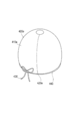
- FIG. 22 is a perspective view showing a medical device set 1a according to another embodiment of the present invention.
- the medical device 400f is integrally configured with the fusion promoting device 100 to form a medical device set 1a, which is also included in one embodiment of the present invention. That is, the medical device 400f constituting the medical device set 1a has a deploying portion 410f, a connecting portion 420, a regulating member 430, a positioning portion 440, and a device connecting portion 450. Since the connecting portion 420, the regulating member 430, and the positioning portion 440 have the same configurations as those of the medical device 400 of the first embodiment having the same reference numerals, the description thereof will be omitted.
- the developing portion 410f includes a curved surface 411, a first end portion 412, a second end portion 413, openings 414, 415, a semi-closed space 416, and a contact portion 417. Since the curved surface 411, the first end portion 412, the second end portion 413, the openings 414, 415, and the semi-closed space 416 are the same as the respective configurations having the same reference numerals in the medical device 400 of the first embodiment. The explanation is omitted.
- the contact portion 417 is configured as a surface provided continuously with the curved surface 411 at one end of the curved surface 411 in the axial direction.
- the contact portion 417 is configured to come into contact with the fusion promoting device 100.
- the contact portion 417 is shown as a flat surface in FIG. 22, but may not be a flat surface as long as the fusion promoting device 100 and the medical device 400f are connected by the device connecting portion 450 at least in part. It may be a curved surface or an irregular shape.
- the device connection unit 450 is configured to connect the fusion promoting device 100 and the medical device 400f in the medical device set 1a.
- the device connecting portion 450 is configured as a filamentous member like the connecting portion 420 in FIG. 22, but if the fusion promoting device and the medical device can be connected, the clip shown in FIG. 18 and the surface shown in FIG. 19 can be connected as described above. It may be composed of a fastener or the like.
- the device connection portion 450 is provided in the vicinity of the inner peripheral edge portion or the inner peripheral edge portion forming the hole 30 of the fusion promoting device 100.
- the position where the device connection portion 450 is provided is arranged radially inward from the punching diameter d (see FIG. 16) of the punching portion 250 when the fusion promoting device 100 is punched by the medical device 200.
- the fusion promoting device is sandwiched between the relevant parts of the living tissue, and when anastomosis is performed by the medical device 200, foreign matter is prevented or suppressed from adhering to the fusion promoting device 100, and surgery or the like is performed. The risk of later suture failure can be reduced.
Landscapes
- Health & Medical Sciences (AREA)
- Life Sciences & Earth Sciences (AREA)
- Surgery (AREA)
- Heart & Thoracic Surgery (AREA)
- Engineering & Computer Science (AREA)
- Biomedical Technology (AREA)
- Nuclear Medicine, Radiotherapy & Molecular Imaging (AREA)
- Medical Informatics (AREA)
- Molecular Biology (AREA)
- Animal Behavior & Ethology (AREA)
- General Health & Medical Sciences (AREA)
- Public Health (AREA)
- Veterinary Medicine (AREA)
- Surgical Instruments (AREA)
Abstract
Le problème décrit par la présente invention est de réduire le risque de fuite anastomotique après une opération telle qu'une opération chirurgicale. La solution selon la présente invention porte sur un outil médical 100 qui est pourvu d'une partie de déploiement 410 qui comprend une surface incurvée 411 comprenant une première partie d'extrémité 412 et une seconde partie d'extrémité 413 disposée sur le côté opposé à la première partie d'extrémité et qui peut former un espace semi-fermé 416 par lequel un dispositif de promotion d'adhérence, pour favoriser l'adhérence de tissus biologiques lorsque la première partie d'extrémité est mise en contact avec la seconde partie d'extrémité, peut être enfermée.
Priority Applications (1)
| Application Number | Priority Date | Filing Date | Title |
|---|---|---|---|
| JP2021551301A JP7471313B2 (ja) | 2019-09-30 | 2020-09-29 | 医療器具及び医療器具セット |
Applications Claiming Priority (2)
| Application Number | Priority Date | Filing Date | Title |
|---|---|---|---|
| JP2019179221 | 2019-09-30 | ||
| JP2019-179221 | 2019-09-30 |
Publications (1)
| Publication Number | Publication Date |
|---|---|
| WO2021065896A1 true WO2021065896A1 (fr) | 2021-04-08 |
Family
ID=75338327
Family Applications (1)
| Application Number | Title | Priority Date | Filing Date |
|---|---|---|---|
| PCT/JP2020/036860 Ceased WO2021065896A1 (fr) | 2019-09-30 | 2020-09-29 | Outil médical et ensemble d'outils médicaux |
Country Status (2)
| Country | Link |
|---|---|
| JP (1) | JP7471313B2 (fr) |
| WO (1) | WO2021065896A1 (fr) |
Citations (3)
| Publication number | Priority date | Publication date | Assignee | Title |
|---|---|---|---|---|
| JP2006110356A (ja) * | 2004-10-18 | 2006-04-27 | Tyco Healthcare Group Lp | 支持構造およびそれを用いる方法 |
| WO2016150861A1 (fr) * | 2015-03-20 | 2016-09-29 | Aesculap Ag | Instrument chirurgical de fusion tissulaire et structure de support correspondante |
| WO2019156230A1 (fr) * | 2018-02-08 | 2019-08-15 | テルモ株式会社 | Appareil médical et dispositif favorisant l'adhérence l'utilisant |
Family Cites Families (2)
| Publication number | Priority date | Publication date | Assignee | Title |
|---|---|---|---|---|
| US6352561B1 (en) | 1996-12-23 | 2002-03-05 | W. L. Gore & Associates | Implant deployment apparatus |
| US9364359B2 (en) | 2011-12-08 | 2016-06-14 | W. L. Gore & Associates, Inc. | Systems and methods for delivery of a medical device |
-
2020
- 2020-09-29 WO PCT/JP2020/036860 patent/WO2021065896A1/fr not_active Ceased
- 2020-09-29 JP JP2021551301A patent/JP7471313B2/ja active Active
Patent Citations (3)
| Publication number | Priority date | Publication date | Assignee | Title |
|---|---|---|---|---|
| JP2006110356A (ja) * | 2004-10-18 | 2006-04-27 | Tyco Healthcare Group Lp | 支持構造およびそれを用いる方法 |
| WO2016150861A1 (fr) * | 2015-03-20 | 2016-09-29 | Aesculap Ag | Instrument chirurgical de fusion tissulaire et structure de support correspondante |
| WO2019156230A1 (fr) * | 2018-02-08 | 2019-08-15 | テルモ株式会社 | Appareil médical et dispositif favorisant l'adhérence l'utilisant |
Also Published As
| Publication number | Publication date |
|---|---|
| JP7471313B2 (ja) | 2024-04-19 |
| JPWO2021065896A1 (fr) | 2021-04-08 |
Similar Documents
| Publication | Publication Date | Title |
|---|---|---|
| JP4754574B2 (ja) | 肥満治療のための装置および方法 | |
| JP2005103302A (ja) | アンフォールディング吻合リング装置 | |
| JP2005103303A (ja) | 内腔間吻合のための単一内腔配置用リング | |
| JP2023049332A (ja) | 医療器具および医療システム | |
| CN111904517A (zh) | 一种血管吻合器 | |
| JPWO2020067380A1 (ja) | 癒合促進デバイスおよび医療デバイス | |
| WO2023189202A1 (fr) | Élément médical | |
| JP7361098B2 (ja) | 癒合促進デバイス | |
| JP2021049191A (ja) | 癒合促進デバイス | |
| JP7248479B2 (ja) | 癒合促進デバイス | |
| US20190282235A1 (en) | Treatment method for joining biological organs | |
| WO2021065896A1 (fr) | Outil médical et ensemble d'outils médicaux | |
| JP7410131B2 (ja) | 癒合促進デバイス | |
| JPH114832A (ja) | 消化管自動吻合装置の補助具 | |
| JP2021053132A (ja) | 医療器具セット、カバー部材、及び癒合促進デバイス | |
| JP7410130B2 (ja) | 癒合促進デバイス | |
| JP2019162405A (ja) | 処置方法 | |
| JP7797285B2 (ja) | 医療用デバイス | |
| JP2023150128A (ja) | 医療用部材および医療用デバイス | |
| JP2022147528A (ja) | 癒合促進デバイスおよび医療器具セット | |
| WO2021060361A1 (fr) | Dispositif favorisant la fusion | |
| JP2020162749A (ja) | 癒合促進デバイス | |
| WO2022071214A1 (fr) | Ensemble équipement médical | |
| JP2023150124A (ja) | 医療用デバイス | |
| JP2021049168A (ja) | 癒合促進デバイスおよび医療デバイス |
Legal Events
| Date | Code | Title | Description |
|---|---|---|---|
| 121 | Ep: the epo has been informed by wipo that ep was designated in this application |
Ref document number: 20871686 Country of ref document: EP Kind code of ref document: A1 |
|
| ENP | Entry into the national phase |
Ref document number: 2021551301 Country of ref document: JP Kind code of ref document: A |
|
| NENP | Non-entry into the national phase |
Ref country code: DE |
|
| 122 | Ep: pct application non-entry in european phase |
Ref document number: 20871686 Country of ref document: EP Kind code of ref document: A1 |