WO2021106873A1 - Dispositif de commande de véhicule, procédé de commande de véhicule et système de commande de véhicule - Google Patents
Dispositif de commande de véhicule, procédé de commande de véhicule et système de commande de véhicule Download PDFInfo
- Publication number
- WO2021106873A1 WO2021106873A1 PCT/JP2020/043672 JP2020043672W WO2021106873A1 WO 2021106873 A1 WO2021106873 A1 WO 2021106873A1 JP 2020043672 W JP2020043672 W JP 2020043672W WO 2021106873 A1 WO2021106873 A1 WO 2021106873A1
- Authority
- WO
- WIPO (PCT)
- Prior art keywords
- vehicle
- control
- control command
- control device
- acquired
- Prior art date
- Legal status (The legal status is an assumption and is not a legal conclusion. Google has not performed a legal analysis and makes no representation as to the accuracy of the status listed.)
- Ceased
Links
Images



Classifications
-
- B—PERFORMING OPERATIONS; TRANSPORTING
- B62—LAND VEHICLES FOR TRAVELLING OTHERWISE THAN ON RAILS
- B62D—MOTOR VEHICLES; TRAILERS
- B62D6/00—Arrangements for automatically controlling steering depending on driving conditions sensed and responded to, e.g. control circuits
- B62D6/04—Arrangements for automatically controlling steering depending on driving conditions sensed and responded to, e.g. control circuits responsive only to forces disturbing the intended course of the vehicle, e.g. forces acting transversely to the direction of vehicle travel
-
- B—PERFORMING OPERATIONS; TRANSPORTING
- B60—VEHICLES IN GENERAL
- B60G—VEHICLE SUSPENSION ARRANGEMENTS
- B60G17/00—Resilient suspensions having means for adjusting the spring or vibration-damper characteristics, for regulating the distance between a supporting surface and a sprung part of vehicle or for locking suspension during use to meet varying vehicular or surface conditions, e.g. due to speed or load
- B60G17/015—Resilient suspensions having means for adjusting the spring or vibration-damper characteristics, for regulating the distance between a supporting surface and a sprung part of vehicle or for locking suspension during use to meet varying vehicular or surface conditions, e.g. due to speed or load the regulating means comprising electric or electronic elements
-
- B—PERFORMING OPERATIONS; TRANSPORTING
- B60—VEHICLES IN GENERAL
- B60G—VEHICLE SUSPENSION ARRANGEMENTS
- B60G17/00—Resilient suspensions having means for adjusting the spring or vibration-damper characteristics, for regulating the distance between a supporting surface and a sprung part of vehicle or for locking suspension during use to meet varying vehicular or surface conditions, e.g. due to speed or load
- B60G17/015—Resilient suspensions having means for adjusting the spring or vibration-damper characteristics, for regulating the distance between a supporting surface and a sprung part of vehicle or for locking suspension during use to meet varying vehicular or surface conditions, e.g. due to speed or load the regulating means comprising electric or electronic elements
- B60G17/016—Resilient suspensions having means for adjusting the spring or vibration-damper characteristics, for regulating the distance between a supporting surface and a sprung part of vehicle or for locking suspension during use to meet varying vehicular or surface conditions, e.g. due to speed or load the regulating means comprising electric or electronic elements characterised by their responsiveness, when the vehicle is travelling, to specific motion, a specific condition, or driver input
- B60G17/0165—Resilient suspensions having means for adjusting the spring or vibration-damper characteristics, for regulating the distance between a supporting surface and a sprung part of vehicle or for locking suspension during use to meet varying vehicular or surface conditions, e.g. due to speed or load the regulating means comprising electric or electronic elements characterised by their responsiveness, when the vehicle is travelling, to specific motion, a specific condition, or driver input to an external condition, e.g. rough road surface, side wind
-
- B—PERFORMING OPERATIONS; TRANSPORTING
- B60—VEHICLES IN GENERAL
- B60G—VEHICLE SUSPENSION ARRANGEMENTS
- B60G17/00—Resilient suspensions having means for adjusting the spring or vibration-damper characteristics, for regulating the distance between a supporting surface and a sprung part of vehicle or for locking suspension during use to meet varying vehicular or surface conditions, e.g. due to speed or load
- B60G17/015—Resilient suspensions having means for adjusting the spring or vibration-damper characteristics, for regulating the distance between a supporting surface and a sprung part of vehicle or for locking suspension during use to meet varying vehicular or surface conditions, e.g. due to speed or load the regulating means comprising electric or electronic elements
- B60G17/0195—Resilient suspensions having means for adjusting the spring or vibration-damper characteristics, for regulating the distance between a supporting surface and a sprung part of vehicle or for locking suspension during use to meet varying vehicular or surface conditions, e.g. due to speed or load the regulating means comprising electric or electronic elements characterised by the regulation being combined with other vehicle control systems
-
- B—PERFORMING OPERATIONS; TRANSPORTING
- B60—VEHICLES IN GENERAL
- B60T—VEHICLE BRAKE CONTROL SYSTEMS OR PARTS THEREOF; BRAKE CONTROL SYSTEMS OR PARTS THEREOF, IN GENERAL; ARRANGEMENT OF BRAKING ELEMENTS ON VEHICLES IN GENERAL; PORTABLE DEVICES FOR PREVENTING UNWANTED MOVEMENT OF VEHICLES; VEHICLE MODIFICATIONS TO FACILITATE COOLING OF BRAKES
- B60T7/00—Brake-action initiating means
- B60T7/12—Brake-action initiating means for automatic initiation; for initiation not subject to will of driver or passenger
- B60T7/22—Brake-action initiating means for automatic initiation; for initiation not subject to will of driver or passenger initiated by contact of vehicle, e.g. bumper, with an external object, e.g. another vehicle, or by means of contactless obstacle detectors mounted on the vehicle
-
- B—PERFORMING OPERATIONS; TRANSPORTING
- B60—VEHICLES IN GENERAL
- B60T—VEHICLE BRAKE CONTROL SYSTEMS OR PARTS THEREOF; BRAKE CONTROL SYSTEMS OR PARTS THEREOF, IN GENERAL; ARRANGEMENT OF BRAKING ELEMENTS ON VEHICLES IN GENERAL; PORTABLE DEVICES FOR PREVENTING UNWANTED MOVEMENT OF VEHICLES; VEHICLE MODIFICATIONS TO FACILITATE COOLING OF BRAKES
- B60T8/00—Arrangements for adjusting wheel-braking force to meet varying vehicular or ground-surface conditions, e.g. limiting or varying distribution of braking force
- B60T8/17—Using electrical or electronic regulation means to control braking
- B60T8/1755—Brake regulation specially adapted to control the stability of the vehicle, e.g. taking into account yaw rate or transverse acceleration in a curve
- B60T8/17557—Brake regulation specially adapted to control the stability of the vehicle, e.g. taking into account yaw rate or transverse acceleration in a curve specially adapted for lane departure prevention
-
- B—PERFORMING OPERATIONS; TRANSPORTING
- B60—VEHICLES IN GENERAL
- B60W—CONJOINT CONTROL OF VEHICLE SUB-UNITS OF DIFFERENT TYPE OR DIFFERENT FUNCTION; CONTROL SYSTEMS SPECIALLY ADAPTED FOR HYBRID VEHICLES; ROAD VEHICLE DRIVE CONTROL SYSTEMS FOR PURPOSES NOT RELATED TO THE CONTROL OF A PARTICULAR SUB-UNIT
- B60W10/00—Conjoint control of vehicle sub-units of different type or different function
-
- B—PERFORMING OPERATIONS; TRANSPORTING
- B60—VEHICLES IN GENERAL
- B60W—CONJOINT CONTROL OF VEHICLE SUB-UNITS OF DIFFERENT TYPE OR DIFFERENT FUNCTION; CONTROL SYSTEMS SPECIALLY ADAPTED FOR HYBRID VEHICLES; ROAD VEHICLE DRIVE CONTROL SYSTEMS FOR PURPOSES NOT RELATED TO THE CONTROL OF A PARTICULAR SUB-UNIT
- B60W10/00—Conjoint control of vehicle sub-units of different type or different function
- B60W10/04—Conjoint control of vehicle sub-units of different type or different function including control of propulsion units
-
- B—PERFORMING OPERATIONS; TRANSPORTING
- B60—VEHICLES IN GENERAL
- B60W—CONJOINT CONTROL OF VEHICLE SUB-UNITS OF DIFFERENT TYPE OR DIFFERENT FUNCTION; CONTROL SYSTEMS SPECIALLY ADAPTED FOR HYBRID VEHICLES; ROAD VEHICLE DRIVE CONTROL SYSTEMS FOR PURPOSES NOT RELATED TO THE CONTROL OF A PARTICULAR SUB-UNIT
- B60W10/00—Conjoint control of vehicle sub-units of different type or different function
- B60W10/18—Conjoint control of vehicle sub-units of different type or different function including control of braking systems
-
- B—PERFORMING OPERATIONS; TRANSPORTING
- B60—VEHICLES IN GENERAL
- B60W—CONJOINT CONTROL OF VEHICLE SUB-UNITS OF DIFFERENT TYPE OR DIFFERENT FUNCTION; CONTROL SYSTEMS SPECIALLY ADAPTED FOR HYBRID VEHICLES; ROAD VEHICLE DRIVE CONTROL SYSTEMS FOR PURPOSES NOT RELATED TO THE CONTROL OF A PARTICULAR SUB-UNIT
- B60W10/00—Conjoint control of vehicle sub-units of different type or different function
- B60W10/20—Conjoint control of vehicle sub-units of different type or different function including control of steering systems
-
- B—PERFORMING OPERATIONS; TRANSPORTING
- B60—VEHICLES IN GENERAL
- B60W—CONJOINT CONTROL OF VEHICLE SUB-UNITS OF DIFFERENT TYPE OR DIFFERENT FUNCTION; CONTROL SYSTEMS SPECIALLY ADAPTED FOR HYBRID VEHICLES; ROAD VEHICLE DRIVE CONTROL SYSTEMS FOR PURPOSES NOT RELATED TO THE CONTROL OF A PARTICULAR SUB-UNIT
- B60W10/00—Conjoint control of vehicle sub-units of different type or different function
- B60W10/22—Conjoint control of vehicle sub-units of different type or different function including control of suspension systems
-
- B—PERFORMING OPERATIONS; TRANSPORTING
- B60—VEHICLES IN GENERAL
- B60W—CONJOINT CONTROL OF VEHICLE SUB-UNITS OF DIFFERENT TYPE OR DIFFERENT FUNCTION; CONTROL SYSTEMS SPECIALLY ADAPTED FOR HYBRID VEHICLES; ROAD VEHICLE DRIVE CONTROL SYSTEMS FOR PURPOSES NOT RELATED TO THE CONTROL OF A PARTICULAR SUB-UNIT
- B60W30/00—Purposes of road vehicle drive control systems not related to the control of a particular sub-unit, e.g. of systems using conjoint control of vehicle sub-units
- B60W30/02—Control of vehicle driving stability
-
- B—PERFORMING OPERATIONS; TRANSPORTING
- B60—VEHICLES IN GENERAL
- B60W—CONJOINT CONTROL OF VEHICLE SUB-UNITS OF DIFFERENT TYPE OR DIFFERENT FUNCTION; CONTROL SYSTEMS SPECIALLY ADAPTED FOR HYBRID VEHICLES; ROAD VEHICLE DRIVE CONTROL SYSTEMS FOR PURPOSES NOT RELATED TO THE CONTROL OF A PARTICULAR SUB-UNIT
- B60W30/00—Purposes of road vehicle drive control systems not related to the control of a particular sub-unit, e.g. of systems using conjoint control of vehicle sub-units
- B60W30/10—Path keeping
-
- B—PERFORMING OPERATIONS; TRANSPORTING
- B62—LAND VEHICLES FOR TRAVELLING OTHERWISE THAN ON RAILS
- B62D—MOTOR VEHICLES; TRAILERS
- B62D15/00—Steering not otherwise provided for
- B62D15/02—Steering position indicators ; Steering position determination; Steering aids
- B62D15/025—Active steering aids, e.g. helping the driver by actively influencing the steering system after environment evaluation
-
- B—PERFORMING OPERATIONS; TRANSPORTING
- B62—LAND VEHICLES FOR TRAVELLING OTHERWISE THAN ON RAILS
- B62D—MOTOR VEHICLES; TRAILERS
- B62D15/00—Steering not otherwise provided for
- B62D15/02—Steering position indicators ; Steering position determination; Steering aids
- B62D15/025—Active steering aids, e.g. helping the driver by actively influencing the steering system after environment evaluation
- B62D15/0265—Automatic obstacle avoidance by steering
-
- B—PERFORMING OPERATIONS; TRANSPORTING
- B62—LAND VEHICLES FOR TRAVELLING OTHERWISE THAN ON RAILS
- B62D—MOTOR VEHICLES; TRAILERS
- B62D17/00—Means on vehicles for adjusting camber, castor, or toe-in
-
- F—MECHANICAL ENGINEERING; LIGHTING; HEATING; WEAPONS; BLASTING
- F02—COMBUSTION ENGINES; HOT-GAS OR COMBUSTION-PRODUCT ENGINE PLANTS
- F02D—CONTROLLING COMBUSTION ENGINES
- F02D29/00—Controlling engines, such controlling being peculiar to the devices driven thereby, the devices being other than parts or accessories essential to engine operation, e.g. controlling of engines by signals external thereto
- F02D29/02—Controlling engines, such controlling being peculiar to the devices driven thereby, the devices being other than parts or accessories essential to engine operation, e.g. controlling of engines by signals external thereto peculiar to engines driving vehicles; peculiar to engines driving variable pitch propellers
-
- B—PERFORMING OPERATIONS; TRANSPORTING
- B60—VEHICLES IN GENERAL
- B60G—VEHICLE SUSPENSION ARRANGEMENTS
- B60G2200/00—Indexing codes relating to suspension types
- B60G2200/40—Indexing codes relating to the wheels in the suspensions
- B60G2200/462—Toe-in/out
- B60G2200/4622—Alignment adjustment
-
- B—PERFORMING OPERATIONS; TRANSPORTING
- B60—VEHICLES IN GENERAL
- B60G—VEHICLE SUSPENSION ARRANGEMENTS
- B60G2400/00—Indexing codes relating to detected, measured or calculated conditions or factors
- B60G2400/20—Speed
- B60G2400/204—Vehicle speed
-
- B—PERFORMING OPERATIONS; TRANSPORTING
- B60—VEHICLES IN GENERAL
- B60G—VEHICLE SUSPENSION ARRANGEMENTS
- B60G2400/00—Indexing codes relating to detected, measured or calculated conditions or factors
- B60G2400/80—Exterior conditions
- B60G2400/82—Ground surface
- B60G2400/821—Uneven, rough road sensing affecting vehicle body vibration
-
- B—PERFORMING OPERATIONS; TRANSPORTING
- B60—VEHICLES IN GENERAL
- B60G—VEHICLE SUSPENSION ARRANGEMENTS
- B60G2400/00—Indexing codes relating to detected, measured or calculated conditions or factors
- B60G2400/80—Exterior conditions
- B60G2400/82—Ground surface
- B60G2400/824—Travel path sensing; Track monitoring
-
- B—PERFORMING OPERATIONS; TRANSPORTING
- B60—VEHICLES IN GENERAL
- B60G—VEHICLE SUSPENSION ARRANGEMENTS
- B60G2401/00—Indexing codes relating to the type of sensors based on the principle of their operation
- B60G2401/14—Photo or light sensitive means, e.g. Infrared
- B60G2401/142—Visual Display Camera, e.g. LCD
-
- B—PERFORMING OPERATIONS; TRANSPORTING
- B60—VEHICLES IN GENERAL
- B60G—VEHICLE SUSPENSION ARRANGEMENTS
- B60G2401/00—Indexing codes relating to the type of sensors based on the principle of their operation
- B60G2401/16—GPS track data
-
- B—PERFORMING OPERATIONS; TRANSPORTING
- B60—VEHICLES IN GENERAL
- B60G—VEHICLE SUSPENSION ARRANGEMENTS
- B60G2500/00—Indexing codes relating to the regulated action or device
- B60G2500/10—Damping action or damper
-
- B—PERFORMING OPERATIONS; TRANSPORTING
- B60—VEHICLES IN GENERAL
- B60G—VEHICLE SUSPENSION ARRANGEMENTS
- B60G2500/00—Indexing codes relating to the regulated action or device
- B60G2500/30—Height or ground clearance
-
- B—PERFORMING OPERATIONS; TRANSPORTING
- B60—VEHICLES IN GENERAL
- B60G—VEHICLE SUSPENSION ARRANGEMENTS
- B60G2800/00—Indexing codes relating to the type of movement or to the condition of the vehicle and to the end result to be achieved by the control action
- B60G2800/01—Attitude or posture control
- B60G2800/012—Rolling condition
-
- B—PERFORMING OPERATIONS; TRANSPORTING
- B60—VEHICLES IN GENERAL
- B60G—VEHICLE SUSPENSION ARRANGEMENTS
- B60G2800/00—Indexing codes relating to the type of movement or to the condition of the vehicle and to the end result to be achieved by the control action
- B60G2800/01—Attitude or posture control
- B60G2800/014—Pitch; Nose dive
-
- B—PERFORMING OPERATIONS; TRANSPORTING
- B60—VEHICLES IN GENERAL
- B60G—VEHICLE SUSPENSION ARRANGEMENTS
- B60G2800/00—Indexing codes relating to the type of movement or to the condition of the vehicle and to the end result to be achieved by the control action
- B60G2800/01—Attitude or posture control
- B60G2800/016—Yawing condition
-
- B—PERFORMING OPERATIONS; TRANSPORTING
- B60—VEHICLES IN GENERAL
- B60T—VEHICLE BRAKE CONTROL SYSTEMS OR PARTS THEREOF; BRAKE CONTROL SYSTEMS OR PARTS THEREOF, IN GENERAL; ARRANGEMENT OF BRAKING ELEMENTS ON VEHICLES IN GENERAL; PORTABLE DEVICES FOR PREVENTING UNWANTED MOVEMENT OF VEHICLES; VEHICLE MODIFICATIONS TO FACILITATE COOLING OF BRAKES
- B60T2260/00—Interaction of vehicle brake system with other systems
- B60T2260/02—Active Steering, Steer-by-Wire
-
- B—PERFORMING OPERATIONS; TRANSPORTING
- B60—VEHICLES IN GENERAL
- B60T—VEHICLE BRAKE CONTROL SYSTEMS OR PARTS THEREOF; BRAKE CONTROL SYSTEMS OR PARTS THEREOF, IN GENERAL; ARRANGEMENT OF BRAKING ELEMENTS ON VEHICLES IN GENERAL; PORTABLE DEVICES FOR PREVENTING UNWANTED MOVEMENT OF VEHICLES; VEHICLE MODIFICATIONS TO FACILITATE COOLING OF BRAKES
- B60T2260/00—Interaction of vehicle brake system with other systems
- B60T2260/06—Active Suspension System
-
- B—PERFORMING OPERATIONS; TRANSPORTING
- B60—VEHICLES IN GENERAL
- B60W—CONJOINT CONTROL OF VEHICLE SUB-UNITS OF DIFFERENT TYPE OR DIFFERENT FUNCTION; CONTROL SYSTEMS SPECIALLY ADAPTED FOR HYBRID VEHICLES; ROAD VEHICLE DRIVE CONTROL SYSTEMS FOR PURPOSES NOT RELATED TO THE CONTROL OF A PARTICULAR SUB-UNIT
- B60W2420/00—Indexing codes relating to the type of sensors based on the principle of their operation
- B60W2420/40—Photo, light or radio wave sensitive means, e.g. infrared sensors
- B60W2420/403—Image sensing, e.g. optical camera
-
- B—PERFORMING OPERATIONS; TRANSPORTING
- B60—VEHICLES IN GENERAL
- B60W—CONJOINT CONTROL OF VEHICLE SUB-UNITS OF DIFFERENT TYPE OR DIFFERENT FUNCTION; CONTROL SYSTEMS SPECIALLY ADAPTED FOR HYBRID VEHICLES; ROAD VEHICLE DRIVE CONTROL SYSTEMS FOR PURPOSES NOT RELATED TO THE CONTROL OF A PARTICULAR SUB-UNIT
- B60W2520/00—Input parameters relating to overall vehicle dynamics
- B60W2520/10—Longitudinal speed
-
- B—PERFORMING OPERATIONS; TRANSPORTING
- B60—VEHICLES IN GENERAL
- B60W—CONJOINT CONTROL OF VEHICLE SUB-UNITS OF DIFFERENT TYPE OR DIFFERENT FUNCTION; CONTROL SYSTEMS SPECIALLY ADAPTED FOR HYBRID VEHICLES; ROAD VEHICLE DRIVE CONTROL SYSTEMS FOR PURPOSES NOT RELATED TO THE CONTROL OF A PARTICULAR SUB-UNIT
- B60W2520/00—Input parameters relating to overall vehicle dynamics
- B60W2520/14—Yaw
-
- B—PERFORMING OPERATIONS; TRANSPORTING
- B60—VEHICLES IN GENERAL
- B60W—CONJOINT CONTROL OF VEHICLE SUB-UNITS OF DIFFERENT TYPE OR DIFFERENT FUNCTION; CONTROL SYSTEMS SPECIALLY ADAPTED FOR HYBRID VEHICLES; ROAD VEHICLE DRIVE CONTROL SYSTEMS FOR PURPOSES NOT RELATED TO THE CONTROL OF A PARTICULAR SUB-UNIT
- B60W2530/00—Input parameters relating to vehicle conditions or values, not covered by groups B60W2510/00 or B60W2520/00
- B60W2530/16—Driving resistance
-
- B—PERFORMING OPERATIONS; TRANSPORTING
- B60—VEHICLES IN GENERAL
- B60W—CONJOINT CONTROL OF VEHICLE SUB-UNITS OF DIFFERENT TYPE OR DIFFERENT FUNCTION; CONTROL SYSTEMS SPECIALLY ADAPTED FOR HYBRID VEHICLES; ROAD VEHICLE DRIVE CONTROL SYSTEMS FOR PURPOSES NOT RELATED TO THE CONTROL OF A PARTICULAR SUB-UNIT
- B60W2552/00—Input parameters relating to infrastructure
- B60W2552/30—Road curve radius
-
- B—PERFORMING OPERATIONS; TRANSPORTING
- B60—VEHICLES IN GENERAL
- B60W—CONJOINT CONTROL OF VEHICLE SUB-UNITS OF DIFFERENT TYPE OR DIFFERENT FUNCTION; CONTROL SYSTEMS SPECIALLY ADAPTED FOR HYBRID VEHICLES; ROAD VEHICLE DRIVE CONTROL SYSTEMS FOR PURPOSES NOT RELATED TO THE CONTROL OF A PARTICULAR SUB-UNIT
- B60W2552/00—Input parameters relating to infrastructure
- B60W2552/35—Road bumpiness, e.g. potholes
-
- B—PERFORMING OPERATIONS; TRANSPORTING
- B60—VEHICLES IN GENERAL
- B60W—CONJOINT CONTROL OF VEHICLE SUB-UNITS OF DIFFERENT TYPE OR DIFFERENT FUNCTION; CONTROL SYSTEMS SPECIALLY ADAPTED FOR HYBRID VEHICLES; ROAD VEHICLE DRIVE CONTROL SYSTEMS FOR PURPOSES NOT RELATED TO THE CONTROL OF A PARTICULAR SUB-UNIT
- B60W2555/00—Input parameters relating to exterior conditions, not covered by groups B60W2552/00, B60W2554/00
- B60W2555/20—Ambient conditions, e.g. wind or rain
-
- B—PERFORMING OPERATIONS; TRANSPORTING
- B60—VEHICLES IN GENERAL
- B60W—CONJOINT CONTROL OF VEHICLE SUB-UNITS OF DIFFERENT TYPE OR DIFFERENT FUNCTION; CONTROL SYSTEMS SPECIALLY ADAPTED FOR HYBRID VEHICLES; ROAD VEHICLE DRIVE CONTROL SYSTEMS FOR PURPOSES NOT RELATED TO THE CONTROL OF A PARTICULAR SUB-UNIT
- B60W2556/00—Input parameters relating to data
- B60W2556/45—External transmission of data to or from the vehicle
- B60W2556/50—External transmission of data to or from the vehicle of positioning data, e.g. GPS [Global Positioning System] data
-
- B—PERFORMING OPERATIONS; TRANSPORTING
- B60—VEHICLES IN GENERAL
- B60W—CONJOINT CONTROL OF VEHICLE SUB-UNITS OF DIFFERENT TYPE OR DIFFERENT FUNCTION; CONTROL SYSTEMS SPECIALLY ADAPTED FOR HYBRID VEHICLES; ROAD VEHICLE DRIVE CONTROL SYSTEMS FOR PURPOSES NOT RELATED TO THE CONTROL OF A PARTICULAR SUB-UNIT
- B60W2710/00—Output or target parameters relating to a particular sub-units
- B60W2710/18—Braking system
-
- B—PERFORMING OPERATIONS; TRANSPORTING
- B60—VEHICLES IN GENERAL
- B60W—CONJOINT CONTROL OF VEHICLE SUB-UNITS OF DIFFERENT TYPE OR DIFFERENT FUNCTION; CONTROL SYSTEMS SPECIALLY ADAPTED FOR HYBRID VEHICLES; ROAD VEHICLE DRIVE CONTROL SYSTEMS FOR PURPOSES NOT RELATED TO THE CONTROL OF A PARTICULAR SUB-UNIT
- B60W2710/00—Output or target parameters relating to a particular sub-units
- B60W2710/20—Steering systems
-
- B—PERFORMING OPERATIONS; TRANSPORTING
- B60—VEHICLES IN GENERAL
- B60W—CONJOINT CONTROL OF VEHICLE SUB-UNITS OF DIFFERENT TYPE OR DIFFERENT FUNCTION; CONTROL SYSTEMS SPECIALLY ADAPTED FOR HYBRID VEHICLES; ROAD VEHICLE DRIVE CONTROL SYSTEMS FOR PURPOSES NOT RELATED TO THE CONTROL OF A PARTICULAR SUB-UNIT
- B60W2710/00—Output or target parameters relating to a particular sub-units
- B60W2710/20—Steering systems
- B60W2710/207—Steering angle of wheels
-
- B—PERFORMING OPERATIONS; TRANSPORTING
- B60—VEHICLES IN GENERAL
- B60W—CONJOINT CONTROL OF VEHICLE SUB-UNITS OF DIFFERENT TYPE OR DIFFERENT FUNCTION; CONTROL SYSTEMS SPECIALLY ADAPTED FOR HYBRID VEHICLES; ROAD VEHICLE DRIVE CONTROL SYSTEMS FOR PURPOSES NOT RELATED TO THE CONTROL OF A PARTICULAR SUB-UNIT
- B60W2710/00—Output or target parameters relating to a particular sub-units
- B60W2710/22—Suspension systems
-
- B—PERFORMING OPERATIONS; TRANSPORTING
- B60—VEHICLES IN GENERAL
- B60W—CONJOINT CONTROL OF VEHICLE SUB-UNITS OF DIFFERENT TYPE OR DIFFERENT FUNCTION; CONTROL SYSTEMS SPECIALLY ADAPTED FOR HYBRID VEHICLES; ROAD VEHICLE DRIVE CONTROL SYSTEMS FOR PURPOSES NOT RELATED TO THE CONTROL OF A PARTICULAR SUB-UNIT
- B60W2720/00—Output or target parameters relating to overall vehicle dynamics
- B60W2720/10—Longitudinal speed
-
- B—PERFORMING OPERATIONS; TRANSPORTING
- B60—VEHICLES IN GENERAL
- B60W—CONJOINT CONTROL OF VEHICLE SUB-UNITS OF DIFFERENT TYPE OR DIFFERENT FUNCTION; CONTROL SYSTEMS SPECIALLY ADAPTED FOR HYBRID VEHICLES; ROAD VEHICLE DRIVE CONTROL SYSTEMS FOR PURPOSES NOT RELATED TO THE CONTROL OF A PARTICULAR SUB-UNIT
- B60W2720/00—Output or target parameters relating to overall vehicle dynamics
- B60W2720/10—Longitudinal speed
- B60W2720/106—Longitudinal acceleration
-
- B—PERFORMING OPERATIONS; TRANSPORTING
- B60—VEHICLES IN GENERAL
- B60W—CONJOINT CONTROL OF VEHICLE SUB-UNITS OF DIFFERENT TYPE OR DIFFERENT FUNCTION; CONTROL SYSTEMS SPECIALLY ADAPTED FOR HYBRID VEHICLES; ROAD VEHICLE DRIVE CONTROL SYSTEMS FOR PURPOSES NOT RELATED TO THE CONTROL OF A PARTICULAR SUB-UNIT
- B60W2720/00—Output or target parameters relating to overall vehicle dynamics
- B60W2720/14—Yaw
-
- B—PERFORMING OPERATIONS; TRANSPORTING
- B62—LAND VEHICLES FOR TRAVELLING OTHERWISE THAN ON RAILS
- B62D—MOTOR VEHICLES; TRAILERS
- B62D6/00—Arrangements for automatically controlling steering depending on driving conditions sensed and responded to, e.g. control circuits
- B62D6/007—Arrangements for automatically controlling steering depending on driving conditions sensed and responded to, e.g. control circuits adjustable by the driver, e.g. sport mode
Definitions
- the present invention relates to a vehicle control device, a vehicle control method, and a vehicle control system.
- the travel control device of Patent Document 1 sets the target course on the road surface on which the own vehicle travels as the first course based on the map information, and sets the target course on the road surface on which the own vehicle travels based on the rut information.
- the second and third courses are set, the first course is compared with the second and third courses, and the target course on the road surface on which the own vehicle travels is set based on the driving road information and the rut information.
- the present invention has been made in view of the conventional circumstances, and an object of the present invention is a vehicle control device and a vehicle control capable of improving the running stability of a vehicle on a road surface in which a disturbance such as a rut exists.
- the method and the vehicle control system are to be provided.
- the specifications relating to the road condition in front of the vehicle are acquired based on the external world information acquired from the external world recognition unit, and the specifications are obtained based on the specifications relating to the road condition.
- the vehicle behavior control amount for controlling the behavior of the vehicle is acquired based on the estimated state amount of the vehicle and the control amount related to the speed of the vehicle based on the outside world information, and based on the specifications related to the road condition.
- a track tracking control amount for making the vehicle follow the target track is acquired, and the vehicle behavior control amount and the track tracking are obtained.
- a first control command for controlling the suspension device, a second control command for controlling the steering device, and a third control command for controlling the control drive device are output.
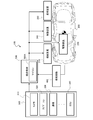
- FIG. 1 is a schematic block diagram showing one aspect of the vehicle control system 100.
- the vehicle 200 of FIG. 1 is a vehicle that can be automatically driven, and has a steering device 210, a suspension device 220, a drive device 230, and a braking device 240.
- the steering device 210 is a device capable of electronically controlling the steering angle by a steering actuator such as an electric power steering (in other words, mechanical steering) or a steer-by-wire system.
- the suspension device 220 is a device capable of electronically controlling the vehicle height and damping force by an energy source such as oil pressure or air pressure such as a fully active suspension or an electronically controlled air suspension.
- the drive device 230 is a device capable of electronically controlling the driving force of a motor, an engine, or the like.
- the braking device 240 is a device capable of electronically controlling the braking force such as a friction brake and a regenerative brake.
- the drive device 230 and the braking device 240 constitute a control drive device capable of electronically controlling the control drive force of the vehicle 200.
- the vehicle control system 100 includes an outside world recognition unit 300, a vehicle behavior detection unit 400, and an integrated control controller 500 (vehicle control device).
- the outside world recognition unit 300 acquires the position of the own vehicle and the outside world information from the outside by a stereo camera 310 that captures the surroundings of the vehicle 200, a navigation system 320 that uses GPS (Global Positioning System) and map information together, and inter-vehicle communication. It also has an electronic control unit 330 (AD-ECU, ADAS-ECU) that controls an automatic operation or an advanced driver assistance system.
- AD-ECU electronice control unit 330
- the outside world recognition unit 300 can include LIDAR (Light Detection and Ranging, Laser Imaging Detection and Ranging) and the like. Further, the electronic control unit 340 has a function of acquiring external world information (peripheral information) through analysis of an image taken by the stereo camera 310 or the like.
- the integrated control controller 500 is an electronic control device including a microcomputer 500A as a control unit that requests a control command for controlling the steering device 210, the suspension device 220, the driving device 230, and the braking device 240.
- the integrated control controller 500 acquires information such as vehicle speed command / acceleration command, road surface displacement, road shape, and surrounding environment from the outside world recognition unit 300, and vehicle behavior (for example, yaw rate, lateral G, etc.) from the vehicle behavior detection unit 400.
- Information on front / rear G, wheel speed, etc.) is acquired, and the acquired information is calculated and processed to obtain and output control commands for controlling each of the steering device 210, suspension device 220, drive device 230, and braking device 240. ..
- the integrated control controller 500 detects the road condition in front of the vehicle, such as the curvature of the road, ruts, snowdrifts, bumps, and potholes, which may disturb the behavior of the vehicle 200, as preview information from the stereo camera 310.
- the integrated control controller 500 detects that a disturbance such as a rut exists on the road surface in front of the vehicle
- the steering device 210, the suspension device 220, the drive device 230, and the braking device 240 use the steering device 210, the suspension device 220, the driving device 240, and the front / rear, left / right, left and right of the vehicle 200.
- integrated control for ensuring the running stability of the vehicle 200 on a road surface where disturbances such as ruts exist is performed.
- the integrated control controller 500 controls the front and rear axes by controlling the driving force by the driving device 230 and the braking device 240, that is, by controlling the engine torque, the motor torque / regenerative brake, and the friction brake, and the left and right axes are controlled.
- the control is performed by controlling the steering angle by the steering device 210, and the control of the vertical axis is performed by controlling the vehicle height and damping force by the suspension device 220.
- ruts, snowdrifts, bumps, and potholes are the specifications related to changes in road surface displacement among the specifications related to road conditions, that is, the recognition results regarding the unevenness of the road surface in the road conditions (in other words, the unevenness of the road surface). Identification information).
- the integrated control controller 500 acquires specifications related to the road condition (specifically, information on changes in the curvature of the road surface and the displacement of the road surface) based on the analysis result of the image taken by the stereo camera 310.
- the integrated control controller 500 performs 3-axis control for ensuring the running stability of the vehicle 200 for each road condition (in other words, the disturbance). For each type of).
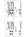
- FIG. 2 is a diagram showing the control contents of the integrated control controller 500 when the vehicle 200 travels on a rutted road surface.
- a rut is a trace of a wheel (in other words, a groove or a recess) that remains on the road surface after a car has passed, and occurs on a snowy road or an unpaved road. The case of ruts on the road will be described.
- the integrated control controller 500 detects a rut in front of the vehicle 200 based on the preview information from the stereo camera 310, the vehicle 200 travels along the rut at the traveling speed of the vehicle 200 before the vehicle 200 enters the rut. Decelerate to a predetermined appropriate vehicle speed that can ensure stability when the vehicle is used. As a result, the integrated control controller 500 causes the vehicle 200 to enter the rut at a speed equal to or lower than the appropriate vehicle speed.
- the integrated control controller 500 adjusts the vehicle 200 to an appropriate vehicle speed by performing control for reducing the driving force generated by the driving device 230 and / or controlling for increasing the braking force generated by the braking device 240. Decelerate to. That is, when the integrated control controller 500 detects a rut in front of the vehicle, the drive device 230 and the drive device 230 and the vehicle speed are lowered as compared with before detecting the rut, in other words, as compared with when traveling on a road surface without ruts. / Or outputs a deceleration control command (third control command) to the braking device 240.
- the integrated control controller 500 raises the vehicle height when the vehicle 200 travels on a rut, as compared with when the vehicle 200 travels on a road surface without ruts.
- a control command (first control command) for raising the vehicle height is output to the suspension device 220.
- the integrated control controller 500 controls the toe-in when the vehicle 200 travels in a rut. carry out.
- the integrated control controller 500 performs toe-in control when the vehicle 200 travels on the rut so that the toe angle of the front wheels is directed more inward than when the vehicle 200 does not travel on the rut, so that the vehicle 200 travels along the rut. Improves stability when doing. As described above, when the vehicle 200 travels in a rut, the integrated control controller 500 performs deceleration to an appropriate vehicle speed for rut travel, an increase in vehicle height, and three-axis control of toe-in, thereby causing the vehicle 200 to perform three-axis control. Ensure stability when driving on ruts.
- the integrated control controller 500 makes the vehicle 200 move along the center of the rut when the vehicle 200 travels in the rut, in other words, the left and right wheels are fitted in the rut.
- a control command (second control command) for the target trajectory is output to the steering device 210 so as to travel along the line.
- the center of the ruts is the center of the distance between the left and right ruts (see FIG. 2).
- the integrated control controller 500 since the integrated control controller 500 has deep ruts, it is not possible to sufficiently suppress the interference between the vehicle 200 and the snow cover even if the control for raising the vehicle height to the maximum is performed. If it is determined that the vehicle cannot be secured, a correction process is performed to offset the target track in automatic driving by a predetermined distance in the left-right direction from the center of the rut, and the steering device 210 is used to drive the vehicle 200 along the corrected target track.
- a control command for the steering angle (second control command) is output to. That is, the integrated control controller 500 acquires the target trajectory based on the specifications related to the disturbance (identification information of the rudder) and the specifications related to the road shape (in other words, the information related to the road shape) in the road surface condition. , A control command (second control command) related to steering is output to the steering device 210 so that the vehicle 200 travels along the target track.
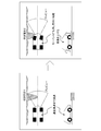
- FIG. 3 shows the control contents of the integrated control controller 500 when the vehicle 200 travels in the snowdrift.
- a snowdrift is a place where snow or fallen leaves are blown by the wind and is deposited on the road or a deposit (convex portion) on the road.
- snow is blown as an example. The case of the snowdrift will be described.
- the traveling speed of the vehicle 200 is set when the vehicle 200 travels in the snowdrift before the vehicle 200 enters the snowdrift. Decelerate to a predetermined appropriate vehicle speed that can ensure stability. As a result, the integrated control controller 500 causes the vehicle 200 to enter the snowdrift at a speed equal to or lower than the appropriate vehicle speed.
- the integrated control controller 500 adjusts the vehicle 200 to an appropriate vehicle speed by performing control for reducing the driving force generated by the driving device 230 and / or controlling for increasing the braking force generated by the braking device 240. Decelerate to. That is, when the integrated control controller 500 detects a snowdrift in front of the vehicle, the vehicle speed is lower than before the snowdrift is detected, in other words, when the vehicle travels on a road surface without a snowdrift. / Or outputs a deceleration control command (third control command) to the braking device 240.
- the integrated control controller 500 raises the vehicle height when the vehicle 200 travels in the snowdrift as compared with when traveling on a road surface without the snowdrift.
- a control command (first control command) for raising the vehicle height is output to the suspension device 220.
- the integrated control controller 500 gives a steering angle control command to the steering device 210 so that when the vehicle 200 travels in the snowdrift, the yaw moment is generated in the direction opposite to the yaw moment generated by the runway resistance due to the snowdrift.
- the second control command) is output to cancel the yaw moment generated by the track resistance of the snowdrift.
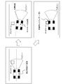
- FIG. 4 shows control of a target trajectory for running the vehicle 200 while avoiding snowdrifts.
- the integrated control controller 500 detects a snowdrift in front of the vehicle 200, if an avoidance condition such as no oncoming vehicle is satisfied, the integrated control controller 500 corrects the target trajectory so as to avoid the snowdrift, and follows the corrected target track.
- the vehicle 200 can be driven. That is, the integrated control controller 500 acquires the target trajectory based on the specifications related to the disturbance in the road surface condition (identification information of the snowdrift) and the specifications related to the road shape (in other words, the information related to the road shape).
- a control command (second control command) related to steering is output to the steering device 210 so that the vehicle 200 travels along the target track.
- FIG. 5 shows the control contents of the integrated control controller 500 when a pothole is detected in front of the vehicle 200.
- the pothole is a hole (or recess) having a length of about 0.1 m to 1 m formed on a paved road surface (for example, asphalt pavement).
- the integrated control controller 500 detects a pothole in front of the vehicle 200 based on the preview information from the stereo camera 310, the vehicle 200 determines the traveling speed of the vehicle 200 and the vehicle 200 determines the pothole before the vehicle 200 enters the pothole. Decelerate to a predetermined appropriate vehicle speed that can ensure stability when driving. As a result, the integrated control controller 500 causes the vehicle 200 to enter the pothole at a speed equal to or lower than the appropriate vehicle speed.
- the integrated control controller 500 adjusts the vehicle 200 to an appropriate vehicle speed by performing control for reducing the driving force generated by the driving device 230 and / or controlling for increasing the braking force generated by the braking device 240. Decelerate to. That is, when the integrated control controller 500 detects a pothole in front of the vehicle, the integrated control controller 500 is driven so that the vehicle speed is lower than before detecting the pothole, in other words, when traveling on a road surface without a pothole.
- a deceleration control command (third control command) is output to the device 230 and / or the braking device 240.
- the integrated control controller 500 outputs a control command for the vehicle height and / or damping force to the suspension device 220 in order to prevent the wheels of the vehicle 200 from falling into the pothole and applying an impact to the vehicle body.
- the integrated control controller 500 tightens the lifting control command (first control command) and / or the damper (in other words, the shock absorber) for the wheels predicted to travel on the pothole, in other words.
- a control command (first control command) for increasing the damping force which is the resistance force generated by the damper, is output to the suspension device 220.
- the integrated control controller 500 can drive the vehicle 200 on a track that avoids the pothole, the integrated control controller 500 corrects the vehicle 200 to a target track that avoids the pothole so that the vehicle 200 runs along the target track. It is possible to output a steering angle control command (second control command) to the steering device 210. That is, the integrated control controller 500 is based on the specifications related to the disturbance in the road surface condition (specifically, the identification information of the pothole) and the specifications related to the road shape (in other words, the information related to the road shape).
- the target track is acquired, and a control command (second control command) related to steering is output to the steering device 210 so that the vehicle 200 travels along the target track.
- FIG. 6 shows the control contents of the integrated control controller 500 when a bump is detected in front of the vehicle 200.
- a bump is a raised object (for example, a speed bump or a speed cushion) that is intentionally installed to encourage the driver to decelerate by indicating a place where a part of the road is raised due to a construction mark or the like. Can be excluded.
- the traveling speed of the vehicle 200 is set when the vehicle 200 travels on the bump before the vehicle 200 enters the bump. Decelerate to a predetermined appropriate vehicle speed that can ensure stability. As a result, the integrated control controller 500 causes the vehicle 200 to enter the bump at a speed equal to or lower than the appropriate vehicle speed.
- the integrated control controller 500 adjusts the vehicle 200 to an appropriate vehicle speed by performing control for reducing the driving force generated by the driving device 230 and / or controlling for increasing the braking force generated by the braking device 240. Decelerate to. That is, when the integrated control controller 500 detects a bump in front of the vehicle, the drive device 230 and the drive device 230 and the vehicle speed are lowered so that the vehicle speed is lower than before the bump is detected, in other words, when the vehicle travels on a road surface without bumps. / Or outputs a deceleration control command (third control command) to the braking device 240.
- the integrated control controller 500 outputs a control command for the vehicle height and / or damping force to the suspension device 220 in order to suppress the vertical vibration of the vehicle 200 when the wheels of the vehicle 200 ride on the bumps.
- the integrated control controller 500 softens the lifting control command (first control command) or the damper (in other words, the shock absorber) for the wheel predicted to ride on the bump, in other words, the damper A control command (first control command) for lowering the damping force, which is the generated resistance force, is output to the suspension device 220.
- the integrated control controller 500 corrects the vehicle 200 to a target track that avoids bumps, and steers the vehicle 200 so that the vehicle 200 travels along the target track. It is possible to output a steering angle control command (second control command) to the device 210. That is, the integrated control controller 500 acquires the target trajectory based on the specifications related to the disturbance in the road surface condition (bump identification information) and the specifications related to the road shape (in other words, information related to the road shape). , A control command (second control command) related to steering is output to the steering device 210 so that the vehicle 200 travels along the target track.
- FIG. 7 shows the control contents of the integrated control controller 500 when a curved road (in other words, the curvature of the road surface) is detected in front of the vehicle 200.
- the integrated control controller 500 detects a curved road in front of the vehicle 200 based on preview information and map information from the stereo camera 310, the traveling speed of the vehicle 200 is set to the vehicle 200 before the vehicle 200 enters the curved road. Decelerates to a predetermined appropriate vehicle speed that can ensure stability when driving on a curved road. As a result, the integrated control controller 500 causes the vehicle 200 to enter the curved road at a speed equal to or lower than the appropriate vehicle speed.
- the integrated control controller 500 adjusts the vehicle 200 to an appropriate vehicle speed by performing control for reducing the driving force generated by the driving device 230 and / or controlling for increasing the braking force generated by the braking device 240. Decelerate to. That is, when the integrated control controller 500 detects a curved road in front of the vehicle, the vehicle speed is lower than before detecting the curved road, in other words, the vehicle speed is lower than when traveling on a straight road. / Or outputs a deceleration control command (third control command) to the braking device 240.
- the integrated control controller 500 gives a vehicle height adjustment control command (first control command) to the suspension device 220 so that the vehicle height on the inside of the turn is lower than the height of the vehicle on the outside of the turn among the left and right vehicle heights of the vehicle 200.
- first control command a vehicle height adjustment control command
- the integrated control controller 500 reduces the vehicle height inside the turn and raises the vehicle height outside the turn from the state where the left and right vehicle heights are controlled to be the same, thereby performing vehicle height control inside the turn.
- the vehicle height of is lower than the vehicle height on the outside of the turn.
- the integrated control controller 500 includes a state estimation unit 510 and an integrated control execution unit 520, and further, the integrated control execution unit 520 includes a vehicle behavior control unit 530, a track tracking control unit 540, and a distribution control unit 550.
- the state estimation unit 510 includes a road surface determination unit 511, a vehicle state quantity estimation unit 512, and a track generation unit 513.
- the road surface determination unit 511 acquires road surface displacement, road shape, peripheral information, etc. from the outside world recognition unit 300, and specifies information such as ruts, snowdrifts, potholes, bumps, etc., that is, specifications related to the road condition including disturbance information. Is calculated and output.
- the vehicle state quantity estimation unit 512 acquires road condition information and the like output by the road surface determination unit 511, and estimates the vehicle condition quantity including the estimated vehicle speed, side slip angle, vehicle height, self-position, and the like.
- the estimated vehicle speed is the vehicle speed data obtained based on the wheel speed information.
- the track generation unit 513 acquires road shape and surrounding information from the outside world recognition unit 300, and also acquires road condition information including disturbance information (for example, identification information such as ruts) from the road surface determination unit 511.
- the track generation unit 513 generates a target track that avoids the disturbance according to conditions such as a state of disturbance such as a snowdrift and the presence or absence of an oncoming vehicle. Further, the track generation unit 513 generates a target track so that the position of the center of gravity of the vehicle 200 moves along the center of the rut when the vehicle 200 travels on the rut, and further, travels along the rut. If it is determined that the vehicle height is not sufficient to enable it, a target track offset from the center of the rut by a predetermined distance in the left-right direction is generated.
- the road surface determination unit 511 determines the road surface condition in front of the vehicle 200 based on the specifications related to the road surface displacement and the specifications related to the road shape, and the track generation unit 513 determines various disturbances related to the road surface condition. Obtain the target trajectory based on the original and the specifications related to the road shape.
- the vehicle behavior control unit 530 of the integrated control execution unit 520 includes a vehicle speed control unit 531 and an attitude control unit 532.
- the vehicle speed control unit 531 acquires information on vehicle speed commands and acceleration commands in automatic driving (advanced driving support) from the outside world recognition unit 300, in other words, information on the control amount related to the speed of the vehicle 200, and estimates the vehicle state amount.
- Information on the estimated vehicle speed is acquired from the unit 512, and further, information on the target vehicle speed according to the disturbance of the road surface is acquired from the attitude control unit 532.
- the vehicle speed control unit 531 determines whether or not there is a deceleration request before entering a disturbance such as a rut from the information of the target vehicle speed according to the disturbance of the road surface and the information of the vehicle speed command in the automatic driving, and determines the final target. Determine the vehicle speed. Further, the vehicle speed control unit 531 obtains the target front-rear acceleration based on the comparison between the final target vehicle speed and the estimated vehicle speed, and outputs the information of the obtained target front-rear acceleration.
- a disturbance such as a rut
- the attitude control unit 532 acquires the information of the target track from the track generation unit 513, and acquires the vehicle state amount information including the approach state of the road surface to the disturbance from the vehicle state amount estimation unit 512, and obtains the information of the vehicle state amount in these. Based on this, the target vehicle height, target roll moment, target lateral acceleration, etc. are calculated and output. That is, when the vehicle 200 travels on a disturbed portion of the road surface such as a rut or a snowdrift, the attitude control unit 532 changes the target vehicle height so as to raise the vehicle height, and the yaw generated by the runway resistance due to the snowdrift.
- the target lateral acceleration is set so as to generate a yaw moment in the direction opposite to the moment.
- the attitude control unit 532 outputs a toe-in request when the vehicle 200 travels on a rut, and outputs a damping force and / or a vehicle height adjustment request when the vehicle 200 travels on a bump or a pothole. Further, when the vehicle 200 travels on a curved road, it outputs a request for left and right vehicle height adjustment.
- the vehicle behavior control unit 530 including the vehicle speed control unit 531 and the attitude control unit 532 controls the vehicle state quantity including the estimated vehicle speed of the vehicle 200, the target track, and the speed of the vehicle 200 (specifically, in detail, The vehicle behavior control amount is acquired based on the vehicle speed command and acceleration command).
- the track tracking control unit 540 acquires information on its own position (own vehicle position) from the vehicle state quantity estimation unit 512 and information on the target track from the track generation unit 513, and traces the vehicle 200 to the target track. Information on the target lateral acceleration (trajectory tracking control amount) of is obtained and output. That is, the track tracking control unit 540 acquires the track tracking control amount based on the self-position of the vehicle 200 and the target track among the estimated state quantities of the vehicle 200.
- the distribution control unit 550 includes a front / rear / pitch control unit 551, an up / down / roll control unit 552, and a left / right / yaw control unit 553, and constitutes a drive device 230, a braking device 240, a suspension device 220, and steering.
- a control command is output to each of the devices 210.
- the front-rear / pitch control unit 551 acquires information on the target front-rear acceleration from the vehicle speed control unit 531, and based on the comparison between the target front-rear acceleration and the actual front-rear acceleration, the control command (third control) for realizing the target front-rear acceleration.
- a drive torque control command is output to the drive device 230, and a braking torque control command is output to the braking device 240.
- the vertical / roll control unit 552 acquires information such as a target vehicle height, a target roll moment, and a target damping force from the attitude control unit 532, and based on these, a control command (first control) for adjusting the vehicle height and damping force. Command) is output to the suspension device 220.
- the left / right / yaw control unit 553 acquires information on the target lateral acceleration from the attitude control unit 532 and the trajectory tracking control unit 540, and issues a control command (second control command) for adjusting the rudder angle based on the information of the steering device 210. Output to.
- the distribution control unit 550 controls the suspension device 220 based on the vehicle behavior control amount from the vehicle behavior control unit 530 and the track follow control amount from the track follow control unit 540. It outputs a command, a second control command for controlling the steering device 210, and a third control command for controlling the control drive device (drive device 230 and braking device 240).
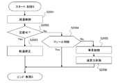
- FIG. 9 is a flowchart showing the procedure of control processing of each of the steering device 210, the suspension device 220, the driving device 230, and the braking device 240 by the integrated control controller 500.
- the integrated control controller 500 determines whether or not the steering device 210, the driving device 230, the braking device 240, and the external world recognition unit 300 are normal, and if any of them is abnormal, the automatic operation and the advanced operation are performed. Since support cannot be provided, the arithmetic processing is terminated without performing various controls.
- step S1100 determines whether or not a rut has been detected in front of the vehicle 200. To do.
- step S1200 determines whether or not a snowdrift is detected in front of the vehicle 200.
- the integrated control controller 500 causes the vehicle 200 to travel along the target track in step S1300. Perform orbit tracking control. Further, the integrated control controller 500 proceeds to step S1400 to perform control (control 1) when the vehicle 200 travels on the rutted road surface.
- step S1401 the integrated control controller 500 implements control drive control for decelerating the vehicle 200 to a predetermined appropriate vehicle speed suitable for rut running before the vehicle 200 enters the rut. That is, in step S1401, the integrated control controller 500 outputs a control command (third control command) for decelerating the vehicle 200 to an appropriate vehicle speed for rut running to the drive device 230 and / or the braking device 240 (FIG. FIG. 2).
- step S1402 determines in step S1402 whether or not the suspension device 220 is normal. Then, if the suspension device 220 is normal, the integrated control controller 500 proceeds to step S1403 and adjusts the vehicle height so that the lower surface of the vehicle 200 does not rub against the snow when traveling with the wheels fitted in the ruts. Control to implement.
- the integrated control controller 500 when the suspension device 220 is normal, the integrated control controller 500 outputs a control command (first control command) for raising the vehicle height of the vehicle 200 to the suspension device 220 in step S1403 (see FIG. 2). ..
- the integrated control controller 500 cancels the vehicle height adjustment by bypassing step S1403 and proceeding to step S1404.
- step S1404 the integrated control controller 500 determines whether or not the vehicle height is secured so that the lower surface of the vehicle 200 is not rubbed by snow. Then, if the vehicle height required for rut running is secured, the integrated control controller 500 bypasses step S1405 and step S1406 and proceeds to step S1407, so that the wheels of the vehicle 200 are fitted into the ruts. Try to run.
- step S1405. Set to offset the target trajectory from the center of the rut. That is, if the vehicle travels in a state where the wheels of the vehicle 200 are fitted in the ruts, the lower surface of the vehicle 200 may be rubbed by snow due to insufficient vehicle height. Therefore, the integrated control controller 500 does not fit the wheels of the vehicle 200 in the ruts. Correct the target trajectory so that it runs on the wheel.
- the integrated control controller 500 outputs a steering angle command (second control command) such that the vehicle 200 traces the corrected target trajectory to the steering device 210. If the target trajectory is corrected in step S1405, the vehicle 200 will travel on a road surface having a large track resistance that the preceding vehicle does not pass through. Therefore, the integrated control controller 500 increases the drive torque in the next step S1406. ..
- the integrated control controller 500 can secure the vehicle height required for rut running, and when the vehicle 200 is run along the rut, the process proceeds to step S1407, and the steering device 210 can adjust the toe angle independently on the left and right. If it is determined whether or not the system is a by-wire system and the toe angle can be adjusted independently on the left and right, the process proceeds to step S1408.
- the integrated control controller 500 is a toe-in control command (first) in which the toe angle of the front wheels is directed more inward than when the wheels are not running in order to improve the stability when the wheels are fitted in the ruts. 2 Control command) is output to the steering device 210 (see FIG. 2).
- step S1200 of the flowchart of FIG. 9 that is, when it detects a rut and a snowdrift in front of the vehicle 200
- the integrated control controller 500 proceeds to step S1500 and moves the vehicle 200 along the target track. Carry out track-following control to drive. Further, the integrated control controller 500 performs control (control 2) for traveling on a snowy road in which ruts and snowdrifts are present in the next step S1600.
- step S1601-step S1608 is the same as that of step S1401-step S1408 described above, and thus detailed description thereof will be omitted.
- the integrated control controller 500 performs deceleration control, vehicle height control, target trajectory correction control, and toe angle control in step S1601-step S1608, and then proceeds to step S1609. Then, the integrated control controller 500 generates a yaw moment in the direction opposite to the yaw moment generated by the runway resistance due to the snowdrift when the vehicle 200 travels in the snowdrift in step S1609 and in step S1609.
- a control command for the steering angle (second control command) is output to offset the yaw moment generated by the runway resistance due to snowdrift (see FIG. 3).
- step S1700 determines whether or not a snowdrift has been detected. Then, when the integrated control controller 500 detects a snowdrift in front of the vehicle, the integrated control controller 500 proceeds to step S1800 to perform track tracking control for traveling the vehicle 200 along the target track, and further, in the next step S1900, the vehicle 200 Controls (control 3) when the vehicle travels in the snowdrift.
- the flowchart of FIG. 12 shows the details of the processing content (control 3) of step S1900.
- step S1901 the integrated control controller 500 implements control drive control for decelerating to a predetermined appropriate vehicle speed suitable for snowdrift running before the vehicle 200 enters the snowdrift. That is, in step S1901, the integrated control controller 500 outputs a control command (third control command) for decelerating the vehicle 200 to an appropriate vehicle speed for snowdrift running to the drive device 230 and / or the braking device 240.
- a control command third control command
- step S1902 the integrated control controller 500 proceeds to step S1902 to determine whether or not it is possible to drive the vehicle 200 while avoiding (bypassing) the snowdrift, such as the presence or absence of an oncoming vehicle, the size and position of the snowdrift, and the like. Judgment is based on driving conditions. Then, when it is possible to avoid the snowdrift, the integrated control controller 500 proceeds to step S1903, and corrects the target trajectory (in other words, the target traveling trajectory) of the vehicle 200 to a track that avoids the snowdrift (FIG. 4), a steering angle command (second control command) for the vehicle 200 to trace the corrected target trajectory is output to the steering device 210.
- the target trajectory in other words, the target traveling trajectory
- a steering angle command second control command
- the integrated control controller 500 proceeds to step S1904 and determines whether or not the suspension device 220 is normal. Then, when the suspension device 220 is normal, the integrated control controller 500 proceeds to step S1905 and performs vehicle height control to raise the vehicle height of the vehicle 200 more than before entering the snowdrift to improve the running stability (). (See FIG. 3).
- the integrated control controller 500 outputs a vehicle height control command (first control command) for raising the vehicle height of the vehicle 200 to the suspension device 220 when the vehicle 200 travels in the snowdrift.
- first control command a vehicle height control command for raising the vehicle height of the vehicle 200 to the suspension device 220 when the vehicle 200 travels in the snowdrift.
- the integrated control controller 500 bypasses step S1905 and proceeds to step S1906 to cancel the vehicle height adjustment.
- step S1906 the integrated control controller 500 controls the steering angle of the steering device 210 so that when the vehicle 200 travels in the snowdrift, the yaw moment is generated in the direction opposite to the yaw moment generated by the runway resistance due to the snowdrift.
- a command (second control command) is output to cancel the yaw moment generated by the runway resistance due to the snowdrift (see FIG. 3).
- step S1700 of the flowchart of FIG. 9 the integrated control controller 500 proceeds to step S2000 and determines whether or not a pothole has been detected. Then, when the integrated control controller 500 detects the pothole, the integrated control controller 500 proceeds to step S2100 to perform track tracking control for traveling the vehicle 200 along the target track.
- control controller 500 executes control (control 4) when the vehicle 200 travels in the pothole in the next step S2200.
- control control 4
- the flowchart of FIG. 13 shows the details of the processing content (control 4) of step S2200.
- step S2201 the integrated control controller 500 implements control drive control for decelerating the vehicle 200 to a predetermined appropriate vehicle speed suitable for pothole driving before the vehicle 200 enters the pothole. That is, in step S2201, the integrated control controller 500 outputs a control command (third control command) for decelerating the vehicle 200 to an appropriate vehicle speed for pothole traveling to the drive device 230 and / or the braking device 240.
- a control command third control command
- step S2202 determines whether or not it is possible to drive the vehicle 200 while avoiding (bypassing) the pothole, as to whether or not there is an oncoming vehicle, the size and position of the pothole. Judgment is made based on driving conditions such as. Then, when it is possible to avoid the pothole, the integrated control controller 500 proceeds to step S2203, corrects the target track of the vehicle 200 to a track that avoids the pothole (see FIG. 5), and after the correction. A steering angle command (second control command) for the vehicle 200 to trace the target trajectory is output to the steering device 210.
- step S2203 corrects the target track of the vehicle 200 to a track that avoids the pothole (see FIG. 5), and after the correction.
- a steering angle command (second control command) for the vehicle 200 to trace the target trajectory is output to the steering device 210.
- the integrated control controller 500 proceeds to step S2204 and determines whether or not the suspension device 220 is normal. Then, when the suspension device 220 is normal, the integrated control controller 500 proceeds to step S2205 and performs vehicle height control for lifting the wheels entering the pothole (see FIG. 5).
- the integrated control controller 500 implements damping force control for hardening the dampers of the wheels entering the pothole, in other words, increasing the damping force (see FIG. 5).
- the integrated control controller 500 may perform either the vehicle height control in step S2205 or the damping force control in step S2206 when the suspension device 220 is a fully active suspension whose vehicle height can be adjusted. it can.
- the integrated control controller 500 can cancel the process of step S2205 and carry out step S2206. In this way, the integrated control controller 500 outputs a control command (first control command) for preventing the wheels from falling into the pothole when the vehicle 200 travels in the pothole, thereby outputting the control command (first control command) to the suspension device 220. , Improves stability when the vehicle 200 travels in a pothole.
- step S2300 determines whether or not a bump has been detected. Then, when the integrated control controller 500 detects a bump, the integrated control controller 500 proceeds to step S2400 to perform track tracking control for traveling the vehicle 200 along the target track.
- control controller 500 executes control (control 5) when the vehicle 200 travels on the bump in the next step S2500.
- control control 5
- the flowchart of FIG. 14 shows the details of the processing content (control 5) of step S2500.
- step S2501 the integrated control controller 500 performs control drive control for decelerating the vehicle 200 to a predetermined appropriate vehicle speed suitable for bump running before the vehicle 200 enters the bump. That is, in step S2501, the integrated control controller 500 outputs a control command (third control command) for decelerating the vehicle 200 to an appropriate vehicle speed for bump traveling to the drive device 230 and / or the braking device 240.
- a control command third control command
- step S2502 the integrated control controller 500 proceeds to step S2502 to determine whether or not the vehicle 200 can be driven by avoiding (bypassing) the bumps, such as the presence or absence of an oncoming vehicle, the size and position of the bumps, and the like. Judgment is based on driving conditions. Then, when it is possible to avoid the bumps, the integrated control controller 500 proceeds to step S2503, corrects the target trajectory of the vehicle 200 to a track that avoids the bumps (see FIG. 6), and corrects the target trajectory. Is output to the steering device 210 so that the vehicle 200 traces the steering angle command (second control command).
- the integrated control controller 500 proceeds to step S2504 and determines whether or not the suspension device 220 is normal. Then, when the suspension device 220 is normal, the integrated control controller 500 proceeds to step S2505 and performs vehicle height control for lifting the wheels entering the bump (see FIG. 6).
- the integrated control controller 500 performs damping force control for softening the damper of the wheel entering the bump, in other words, lowering the damping force (see FIG. 6).
- the integrated control controller 500 may perform either the vehicle height control in step S2505 or the damping force control in step S2506 when the suspension device 220 is a fully active suspension whose vehicle height can be adjusted. it can.
- the integrated control controller 500 can cancel the process of step S2505 and carry out step S2506. In this way, the integrated control controller 500 outputs a control command (first control command) for suppressing the impact from being transmitted to the vehicle body when the vehicle 200 travels on the bump, thereby outputting the vehicle to the suspension device 220. Improves stability when the 200 runs on the bump.
- step S2600 determines whether or not a curved road has been detected. Then, when the integrated control controller 500 detects a curved road, the integrated control controller 500 proceeds to step S2700 to perform track-following control for driving the vehicle 200 along the target track.
- control controller 500 executes control (control 6) when the vehicle 200 travels on a curved road in the next step S2800.
- control 6) when the vehicle 200 travels on a curved road in the next step S2800.
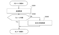
- the flowchart of FIG. 15 shows the details of the processing content (control 6) of step S2800.
- step S2801 the integrated control controller 500 performs control drive control for decelerating to a predetermined appropriate vehicle speed suitable for curve traveling (turning traveling) before the vehicle 200 enters the curved road (see FIG. 7). That is, in step S2801, the integrated control controller 500 outputs a control command (third control command) for decelerating the vehicle 200 to an appropriate vehicle speed for traveling on a curved road to the drive device 230 and / or the braking device 240.
- a control command third control command
- step S2802 the integrated control controller 500 proceeds to step S2802 to determine whether or not the suspension device 220 is normal. Then, when the suspension device 220 is normal, the integrated control controller 500 proceeds to step S2803 to suppress the lateral acceleration (lateral acceleration) felt by the driver (occupant) when the vehicle 200 travels on a curved road. Carry out vehicle height control.
- step S2803 the integrated control controller 500 outputs a vehicle height adjustment control command (first control command) to the suspension device 220 so that the vehicle height inside the turn is lower than the vehicle height outside the turn on the curved road.
- first control command a vehicle height adjustment control command
- the integrated control controller 500 can predict the lateral acceleration generated during the curve traveling and adjust the difference in vehicle height between the inner and outer wheels of the turn based on the prediction result.
- step S2600 of the flowchart of FIG. 9 that is, all of ruts, snowdrifts, potholes, bumps, and curved roads. If a flat and substantially straight road extends in front of the vehicle 200 without detecting the above, the process proceeds to step S2900, and track tracking control for driving the vehicle 200 along the target track is performed.
- the integrated control controller 500 has the snowdrift or bump. Even if it is possible to avoid disturbances such as potholes, the vehicle 200 can be driven without changing the target trajectory. Further, even when the vehicle height of the vehicle 200 can be adjusted to a sufficient height on the rut road surface, the target trajectory of the vehicle 200 is offset to the left and right by a predetermined distance from the center of the rut (the center of the distance between the left and right ruts). Can be made to.
- the vehicle 200 covers a portion where the height of the snowdrift or bump is lower than the predetermined value, or a portion where the depth of the pot hole is shallower than the predetermined value or the size is smaller than the predetermined value.
- the target trajectory of the vehicle 200 can be changed so as to travel.
- the integrated control controller 500 can change the appropriate vehicle speed targeted in the deceleration control before entering the disturbance according to the height of snowdrifts and bumps, or the depth of ruts and potholes.
- the integrated control controller 500 sets the adjustment allowance for the lifting amount and the damping force in the wheel lifting control and the damping force adjustment control when the vehicle 200 travels on the pothole or the bump, by adjusting the depth and size of the pothole. It can be changed according to the height of the bump. Further, the integrated control controller 500 gives a steering angle control command (No. 1) to the steering device 210 so that the yaw moment is generated in the direction opposite to the yaw moment generated when one of the left and right wheels travels on a bump or a pot hole. 2 Control command) can be output.
- the integrated control controller 500 when the integrated control controller 500 detects a bump (for example, a speed bump or a speed cushion) intentionally installed in front of the vehicle 200 to encourage the driver to decelerate, the integrated control controller 500 lifts a wheel that overcomes the bump.
- a control command (first control command) can be output to the suspension device 220 so as to weaken the damping force of the damper of the wheel overcoming the bump.
- the partial unevenness of the road surface on which vehicle control is performed is ruts, snowdrifts, potholes, and bumps, but the disturbance is not limited to these.
- the integrated control controller 500 detects a falling object on a road having a height of a predetermined value or less, a floor plate placed on the road for road construction, etc. as a convex portion as a disturbance, and before entering the disturbance.
- the suspension device 220 is controlled to lift the wheels and / or to weaken the damping force, or is changed to a target trajectory to avoid the convex portion. Steering control can be performed.
Landscapes
- Engineering & Computer Science (AREA)
- Mechanical Engineering (AREA)
- Transportation (AREA)
- Chemical & Material Sciences (AREA)
- Combustion & Propulsion (AREA)
- Automation & Control Theory (AREA)
- General Engineering & Computer Science (AREA)
- Control Of Driving Devices And Active Controlling Of Vehicle (AREA)
- Vehicle Body Suspensions (AREA)
Abstract
Priority Applications (4)
| Application Number | Priority Date | Filing Date | Title |
|---|---|---|---|
| US17/641,562 US12252111B2 (en) | 2019-11-28 | 2020-11-24 | Vehicle control device, vehicle control method, and vehicle control system |
| JP2021561422A JP7320074B2 (ja) | 2019-11-28 | 2020-11-24 | 車両制御装置、車両制御方法、及び車両制御システム |
| CN202080064630.9A CN114390979A (zh) | 2019-11-28 | 2020-11-24 | 车辆控制装置、车辆控制方法及车辆控制系统 |
| EP20891799.7A EP4067126B1 (fr) | 2019-11-28 | 2020-11-24 | Dispositif de commande de véhicule, procédé de commande de véhicule et système de commande de véhicule |
Applications Claiming Priority (2)
| Application Number | Priority Date | Filing Date | Title |
|---|---|---|---|
| JP2019215350 | 2019-11-28 | ||
| JP2019-215350 | 2019-11-28 |
Publications (1)
| Publication Number | Publication Date |
|---|---|
| WO2021106873A1 true WO2021106873A1 (fr) | 2021-06-03 |
Family
ID=76130525
Family Applications (1)
| Application Number | Title | Priority Date | Filing Date |
|---|---|---|---|
| PCT/JP2020/043672 Ceased WO2021106873A1 (fr) | 2019-11-28 | 2020-11-24 | Dispositif de commande de véhicule, procédé de commande de véhicule et système de commande de véhicule |
Country Status (5)
| Country | Link |
|---|---|
| US (1) | US12252111B2 (fr) |
| EP (1) | EP4067126B1 (fr) |
| JP (1) | JP7320074B2 (fr) |
| CN (1) | CN114390979A (fr) |
| WO (1) | WO2021106873A1 (fr) |
Cited By (5)
| Publication number | Priority date | Publication date | Assignee | Title |
|---|---|---|---|---|
| JP2023057397A (ja) * | 2021-10-11 | 2023-04-21 | トヨタ自動車株式会社 | 車両 |
| WO2023214023A1 (fr) * | 2022-05-05 | 2023-11-09 | Jaguar Land Rover Limited | Système et procédé de commande pour suspension de véhicule |
| JP2024056543A (ja) * | 2022-10-11 | 2024-04-23 | 日立Astemo株式会社 | サスペンション制御装置およびサスペンション制御方法 |
| US20240208290A1 (en) * | 2022-12-27 | 2024-06-27 | Hyundai Mobis Co., Ltd. | Apparatus for and method of controlling vehicle suspension |
| GB2632373A (en) * | 2022-05-05 | 2025-02-05 | Jaguar Land Rover Ltd | Control system and method for vehicle suspension |
Families Citing this family (21)
| Publication number | Priority date | Publication date | Assignee | Title |
|---|---|---|---|---|
| JP7259574B2 (ja) * | 2019-06-17 | 2023-04-18 | 株式会社ジェイテクト | 制御装置、および転舵装置 |
| EP4178817A4 (fr) * | 2020-07-10 | 2024-09-11 | Clearmotion, Inc. | Système de freinage intégré de véhicule |
| KR102886281B1 (ko) * | 2020-12-14 | 2025-11-13 | 현대자동차주식회사 | 차량의 과속방지턱 통과 시 제어 방법 |
| US20220340122A1 (en) * | 2021-04-26 | 2022-10-27 | Ford Global Technologies, Llc | Adaptive vehicle systems reactive to changing terrain |
| US12059937B2 (en) * | 2021-10-12 | 2024-08-13 | DRiV Automotive Inc. | Suspension system with roll and pitch stiffness deactivation based on road profile information |
| US11912092B2 (en) | 2021-10-12 | 2024-02-27 | DRiV Automotive Inc. | Suspension leak check systems and methods |
| US11865889B2 (en) | 2021-10-12 | 2024-01-09 | DRiV Automotive Inc. | Suspension system with comfort valves between cross-over hydraulic circuits |
| US12097739B2 (en) | 2021-10-12 | 2024-09-24 | DRiV Automotive Inc. | Pump rinsing systems and methods |
| US11938772B2 (en) | 2021-10-12 | 2024-03-26 | DRiV Automotive Inc. | System for grading filling of a hydraulic suspension system |
| US11904841B2 (en) | 2021-10-12 | 2024-02-20 | DRiV Automotive Inc. | Suspension system integration with advanced driver assistance system |
| US12168378B2 (en) | 2021-10-12 | 2024-12-17 | DRiV Automotive Inc. | Accumulator check systems and methods |
| US11919355B2 (en) | 2021-10-12 | 2024-03-05 | DRiV Automotive Inc. | Valve diagnostic systems and methods |
| US11865887B2 (en) | 2021-10-12 | 2024-01-09 | DRiV Automotive Inc. | Suspension system with incremental roll and pitch stiffness control |
| JP7626081B2 (ja) * | 2022-02-16 | 2025-02-04 | トヨタ自動車株式会社 | 車両制御装置 |
| JP2023159788A (ja) * | 2022-04-20 | 2023-11-01 | Thk株式会社 | サスペンション制御装置及びサスペンション制御方法 |
| JP2024110503A (ja) * | 2023-02-03 | 2024-08-16 | トヨタ自動車株式会社 | 走行制御システム |
| DE102023106353A1 (de) | 2023-03-14 | 2024-09-19 | Dr. Ing. H.C. F. Porsche Aktiengesellschaft | Verfahren zur Regelung eines aktiven Fahrwerks |
| CN118850042A (zh) * | 2023-04-28 | 2024-10-29 | 比亚迪股份有限公司 | 车辆控制方法和装置以及车辆 |
| EP4425945A4 (fr) * | 2023-07-28 | 2024-11-06 | New Automobile Co., Ltd | Système de collecte visuelle situé dans un terminal intelligent d'un véhicule logistique intelligent |
| CN117302895A (zh) * | 2023-10-11 | 2023-12-29 | 浙江中烟工业有限责任公司 | 一种电气单轨小车 |
| CN117228245A (zh) * | 2023-10-16 | 2023-12-15 | 浙江中烟工业有限责任公司 | 用于磨损断裂轨道的ems小车及其紧急停车、车距保持方法 |
Citations (9)
| Publication number | Priority date | Publication date | Assignee | Title |
|---|---|---|---|---|
| JPH0962346A (ja) * | 1995-08-23 | 1997-03-07 | Toyota Motor Corp | 自動操舵システム |
| JP2003146042A (ja) * | 2001-11-13 | 2003-05-21 | Sumitomo Rubber Ind Ltd | 懸架装置 |
| JP2008006995A (ja) * | 2006-06-29 | 2008-01-17 | Toyota Motor Corp | 車両用走行装置 |
| JP2009061945A (ja) * | 2007-09-06 | 2009-03-26 | Toyota Motor Corp | 走行路判定装置および車両走行制御装置 |
| JP2011136627A (ja) * | 2009-12-28 | 2011-07-14 | Honda Motor Co Ltd | 車両制御システム |
| JP2014184747A (ja) * | 2013-03-21 | 2014-10-02 | Toyota Motor Corp | 車両制御装置および車両制御方法 |
| JP2016172500A (ja) | 2015-03-17 | 2016-09-29 | 富士重工業株式会社 | 車両の走行制御装置 |
| WO2018179359A1 (fr) * | 2017-03-31 | 2018-10-04 | 本田技研工業株式会社 | Système de commande de véhicule, procédé de commande de véhicule et programme de commande de véhicule |
| JP2019182188A (ja) * | 2018-04-10 | 2019-10-24 | アイシン精機株式会社 | 車高調整装置 |
Family Cites Families (18)
| Publication number | Priority date | Publication date | Assignee | Title |
|---|---|---|---|---|
| JP3710085B2 (ja) * | 2000-11-08 | 2005-10-26 | 本田技研工業株式会社 | 前後輪駆動車両の制御装置 |
| JP4967806B2 (ja) * | 2007-05-22 | 2012-07-04 | 株式会社日立製作所 | 経路曲率に応じた車両の速度制御装置 |
| US20110153116A1 (en) * | 2009-12-21 | 2011-06-23 | At&T Intellectual Property I, Lp | Determining a status of adherence to a traffic regulation |
| US20120283912A1 (en) * | 2011-05-05 | 2012-11-08 | GM Global Technology Operations LLC | System and method of steering override end detection for automated lane centering |
| KR20130005107A (ko) * | 2011-07-05 | 2013-01-15 | 현대자동차주식회사 | 차간거리 자동 가변 시스템 및 그 방법 |
| JP5754510B2 (ja) * | 2011-09-26 | 2015-07-29 | トヨタ自動車株式会社 | 車両の運転支援システム |
| DE102012004201A1 (de) * | 2012-03-01 | 2012-10-11 | Daimler Ag | Verfahren zur Unterstützung eines Fahrers beim Führen eines Fahrzeugs im Gelände |
| US9037341B2 (en) * | 2012-06-03 | 2015-05-19 | Jerry Alex James | Traction control enable/disable feature |
| JP6035207B2 (ja) * | 2013-06-14 | 2016-11-30 | 日立オートモティブシステムズ株式会社 | 車両制御システム |
| DE102014013585B4 (de) * | 2014-09-13 | 2020-11-05 | Audi Ag | Verfahren zum Kontrollieren eines Verhaltens eines Fahrzeugs |
| US10640109B2 (en) * | 2015-04-10 | 2020-05-05 | Hitachi Automotive Systems, Ltd. | Travel control device for vehicle |
| US9821801B2 (en) * | 2015-06-29 | 2017-11-21 | Mitsubishi Electric Research Laboratories, Inc. | System and method for controlling semi-autonomous vehicles |
| SE541041C2 (en) | 2016-02-24 | 2019-03-19 | Scania Cv Ab | Method and system for controlling a vehicle on a road with wheel grooves |
| DE102017201613A1 (de) * | 2017-02-01 | 2018-08-02 | Bayerische Motoren Werke Aktiengesellschaft | Verfahren, Vorrichtung und Computerprogramm zur Beeinflussung der Führung eines Fahrzeugs abhängig von vertikaldynamischen Einflüssen auf das Fahrzeug |
| JP6285592B1 (ja) * | 2017-03-24 | 2018-02-28 | 株式会社ショーワ | 路面判定装置、サスペンション制御装置、および、サスペンション装置 |
| JP6285591B1 (ja) * | 2017-03-24 | 2018-02-28 | 株式会社ショーワ | サスペンション制御装置、および、サスペンション装置 |
| JP6503585B2 (ja) * | 2017-09-01 | 2019-04-24 | 本田技研工業株式会社 | 車両制御システム、車両制御方法、及びプログラム |
| JP6617126B2 (ja) * | 2017-09-15 | 2019-12-11 | 本田技研工業株式会社 | 走行制御システムおよび車両の制御方法 |
-
2020
- 2020-11-24 JP JP2021561422A patent/JP7320074B2/ja active Active
- 2020-11-24 CN CN202080064630.9A patent/CN114390979A/zh active Pending
- 2020-11-24 US US17/641,562 patent/US12252111B2/en active Active
- 2020-11-24 EP EP20891799.7A patent/EP4067126B1/fr active Active
- 2020-11-24 WO PCT/JP2020/043672 patent/WO2021106873A1/fr not_active Ceased
Patent Citations (9)
| Publication number | Priority date | Publication date | Assignee | Title |
|---|---|---|---|---|
| JPH0962346A (ja) * | 1995-08-23 | 1997-03-07 | Toyota Motor Corp | 自動操舵システム |
| JP2003146042A (ja) * | 2001-11-13 | 2003-05-21 | Sumitomo Rubber Ind Ltd | 懸架装置 |
| JP2008006995A (ja) * | 2006-06-29 | 2008-01-17 | Toyota Motor Corp | 車両用走行装置 |
| JP2009061945A (ja) * | 2007-09-06 | 2009-03-26 | Toyota Motor Corp | 走行路判定装置および車両走行制御装置 |
| JP2011136627A (ja) * | 2009-12-28 | 2011-07-14 | Honda Motor Co Ltd | 車両制御システム |
| JP2014184747A (ja) * | 2013-03-21 | 2014-10-02 | Toyota Motor Corp | 車両制御装置および車両制御方法 |
| JP2016172500A (ja) | 2015-03-17 | 2016-09-29 | 富士重工業株式会社 | 車両の走行制御装置 |
| WO2018179359A1 (fr) * | 2017-03-31 | 2018-10-04 | 本田技研工業株式会社 | Système de commande de véhicule, procédé de commande de véhicule et programme de commande de véhicule |
| JP2019182188A (ja) * | 2018-04-10 | 2019-10-24 | アイシン精機株式会社 | 車高調整装置 |
Non-Patent Citations (1)
| Title |
|---|
| See also references of EP4067126A4 |
Cited By (8)
| Publication number | Priority date | Publication date | Assignee | Title |
|---|---|---|---|---|
| JP2023057397A (ja) * | 2021-10-11 | 2023-04-21 | トヨタ自動車株式会社 | 車両 |
| JP7635694B2 (ja) | 2021-10-11 | 2025-02-26 | トヨタ自動車株式会社 | 車両 |
| WO2023214023A1 (fr) * | 2022-05-05 | 2023-11-09 | Jaguar Land Rover Limited | Système et procédé de commande pour suspension de véhicule |
| GB2632373A (en) * | 2022-05-05 | 2025-02-05 | Jaguar Land Rover Ltd | Control system and method for vehicle suspension |
| GB2632373B (en) * | 2022-05-05 | 2025-07-23 | Jaguar Land Rover Ltd | Control system and method for vehicle suspension |
| JP2024056543A (ja) * | 2022-10-11 | 2024-04-23 | 日立Astemo株式会社 | サスペンション制御装置およびサスペンション制御方法 |
| US20240208290A1 (en) * | 2022-12-27 | 2024-06-27 | Hyundai Mobis Co., Ltd. | Apparatus for and method of controlling vehicle suspension |
| US12384216B2 (en) * | 2022-12-27 | 2025-08-12 | Hyundai Mobis Co., Ltd. | Apparatus for and method of controlling vehicle suspension |
Also Published As
| Publication number | Publication date |
|---|---|
| JP7320074B2 (ja) | 2023-08-02 |
| US20220332306A1 (en) | 2022-10-20 |
| EP4067126B1 (fr) | 2024-08-28 |
| EP4067126A4 (fr) | 2022-12-28 |
| CN114390979A (zh) | 2022-04-22 |
| US12252111B2 (en) | 2025-03-18 |
| JPWO2021106873A1 (fr) | 2021-06-03 |
| EP4067126A1 (fr) | 2022-10-05 |
Similar Documents
| Publication | Publication Date | Title |
|---|---|---|
| JP7320074B2 (ja) | 車両制御装置、車両制御方法、及び車両制御システム | |
| US12350989B2 (en) | Vehicle active suspension control system and method | |
| US20240166193A1 (en) | Active safety suspension system | |
| CN115243907B (zh) | 使用独立致动车轮实现主动悬架的方法和系统 | |
| CN106114120A (zh) | 用于控制机动车辆中的可调整阻尼器的阻尼力的方法 | |
| US20240001924A1 (en) | Collaborative control of vehicle systems | |
| US20180037081A1 (en) | Method for compensating for vertical movements | |
| CN113811469A (zh) | 用于执行车辆自动化驾驶或自主驾驶的方法 | |
| US20230271594A1 (en) | Integrated vehicle braking system | |
| KR20120051553A (ko) | 도로 노면 상태 선행 감지를 통한 차량 서스펜스 제어방법 | |
| US20150360529A1 (en) | Motor vehicle | |
| CN114953884A (zh) | 根据路面的地形特征对车辆的控制 | |
| CN115593391B (zh) | 一种基于电悬架系统的汽车转弯控制方法及系统 | |
| JP7733747B2 (ja) | 車両制御装置、車両制御方法、及び車両制御システム | |
| GB2615425A (en) | Vehicle active suspension control system and method | |
| JP5673300B2 (ja) | 車両用制御装置 | |
| GB2615660A (en) | Vehicle active suspension control system and method | |
| GB2614988A (en) | Vehicle active suspension control system and method | |
| GB2614987A (en) | Vehicle active suspension control system and method | |
| US20260103218A1 (en) | Xyz motion planning for vehicles | |
| KR102643491B1 (ko) | 차량의 댐퍼 제어 시스템 및 방법 | |
| CN118124587A (zh) | 道路特征处理方法及道路特征处理系统 |
Legal Events
| Date | Code | Title | Description |
|---|---|---|---|
| 121 | Ep: the epo has been informed by wipo that ep was designated in this application |
Ref document number: 20891799 Country of ref document: EP Kind code of ref document: A1 |
|
| ENP | Entry into the national phase |
Ref document number: 2021561422 Country of ref document: JP Kind code of ref document: A |
|
| NENP | Non-entry into the national phase |
Ref country code: DE |
|
| ENP | Entry into the national phase |
Ref document number: 2020891799 Country of ref document: EP Effective date: 20220628 |
|
| WWG | Wipo information: grant in national office |
Ref document number: 17641562 Country of ref document: US |