WO2021111601A1 - 絶縁トランスおよびそれを備えた電力変換装置 - Google Patents
絶縁トランスおよびそれを備えた電力変換装置 Download PDFInfo
- Publication number
- WO2021111601A1 WO2021111601A1 PCT/JP2019/047679 JP2019047679W WO2021111601A1 WO 2021111601 A1 WO2021111601 A1 WO 2021111601A1 JP 2019047679 W JP2019047679 W JP 2019047679W WO 2021111601 A1 WO2021111601 A1 WO 2021111601A1
- Authority
- WO
- WIPO (PCT)
- Prior art keywords
- sub
- terminals
- terminal
- main
- windings
- Prior art date
- Legal status (The legal status is an assumption and is not a legal conclusion. Google has not performed a legal analysis and makes no representation as to the accuracy of the status listed.)
- Ceased
Links
Images


Classifications
-
- H—ELECTRICITY
- H02—GENERATION; CONVERSION OR DISTRIBUTION OF ELECTRIC POWER
- H02M—APPARATUS FOR CONVERSION BETWEEN AC AND AC, BETWEEN AC AND DC, OR BETWEEN DC AND DC, AND FOR USE WITH MAINS OR SIMILAR POWER SUPPLY SYSTEMS; CONVERSION OF DC OR AC INPUT POWER INTO SURGE OUTPUT POWER; CONTROL OR REGULATION THEREOF
- H02M3/00—Conversion of DC power input into DC power output
- H02M3/22—Conversion of DC power input into DC power output with intermediate conversion into AC
- H02M3/24—Conversion of DC power input into DC power output with intermediate conversion into AC by static converters
- H02M3/28—Conversion of DC power input into DC power output with intermediate conversion into AC by static converters using discharge tubes with control electrode or semiconductor devices with control electrode to produce the intermediate AC
- H02M3/325—Conversion of DC power input into DC power output with intermediate conversion into AC by static converters using discharge tubes with control electrode or semiconductor devices with control electrode to produce the intermediate AC using devices of a triode or a transistor type requiring continuous application of a control signal
- H02M3/335—Conversion of DC power input into DC power output with intermediate conversion into AC by static converters using discharge tubes with control electrode or semiconductor devices with control electrode to produce the intermediate AC using devices of a triode or a transistor type requiring continuous application of a control signal using semiconductor devices only
- H02M3/33569—Conversion of DC power input into DC power output with intermediate conversion into AC by static converters using discharge tubes with control electrode or semiconductor devices with control electrode to produce the intermediate AC using devices of a triode or a transistor type requiring continuous application of a control signal using semiconductor devices only having several active switching elements
- H02M3/33576—Conversion of DC power input into DC power output with intermediate conversion into AC by static converters using discharge tubes with control electrode or semiconductor devices with control electrode to produce the intermediate AC using devices of a triode or a transistor type requiring continuous application of a control signal using semiconductor devices only having several active switching elements having at least one active switching element at the secondary side of an isolation transformer
- H02M3/33584—Bidirectional converters
-
- H—ELECTRICITY
- H01—ELECTRIC ELEMENTS
- H01F—MAGNETS; INDUCTANCES; TRANSFORMERS; SELECTION OF MATERIALS FOR THEIR MAGNETIC PROPERTIES
- H01F38/00—Adaptations of transformers or inductances for specific applications or functions
-
- H—ELECTRICITY
- H01—ELECTRIC ELEMENTS
- H01F—MAGNETS; INDUCTANCES; TRANSFORMERS; SELECTION OF MATERIALS FOR THEIR MAGNETIC PROPERTIES
- H01F38/00—Adaptations of transformers or inductances for specific applications or functions
- H01F38/08—High-leakage transformers or inductances
-
- H—ELECTRICITY
- H02—GENERATION; CONVERSION OR DISTRIBUTION OF ELECTRIC POWER
- H02M—APPARATUS FOR CONVERSION BETWEEN AC AND AC, BETWEEN AC AND DC, OR BETWEEN DC AND DC, AND FOR USE WITH MAINS OR SIMILAR POWER SUPPLY SYSTEMS; CONVERSION OF DC OR AC INPUT POWER INTO SURGE OUTPUT POWER; CONTROL OR REGULATION THEREOF
- H02M1/00—Details of apparatus for conversion
- H02M1/44—Circuits or arrangements for compensating for electromagnetic interference in converters or inverters
-
- H—ELECTRICITY
- H01—ELECTRIC ELEMENTS
- H01F—MAGNETS; INDUCTANCES; TRANSFORMERS; SELECTION OF MATERIALS FOR THEIR MAGNETIC PROPERTIES
- H01F38/00—Adaptations of transformers or inductances for specific applications or functions
- H01F2038/006—Adaptations of transformers or inductances for specific applications or functions matrix transformer consisting of several interconnected individual transformers working as a whole
Definitions
- This disclosure relates to an isolation transformer and a power conversion device equipped with the isolation transformer.
- the DC power supplied from the isolation transformer including the first and second windings and the first DC power supply is converted into AC power.
- Power including a first power converter applied to the first winding and a second power converter that converts AC power received from the second winding into DC power and supplies it to a second DC power supply.
- the conversion device is disclosed.
- a main object of the present disclosure is to provide a low-cost isolation transformer with high assembly and heat dissipation, and a power conversion device equipped with the isolation transformer.
- the isolation transformer of the present disclosure includes first to Nth sub-isolation transformers that are electrically coupled to each other.
- N is an integer greater than or equal to 2.
- Each of the first to Nth sub-isolation transformers is connected to the first and second sub-windings and the first and second polar terminals of the first sub-windings, respectively.
- the third and fourth sub-terminals connected to the first-polarity terminal and the second-polarity terminal of the second subwinding, respectively.
- the polar directions of the first and second subwindings are the same.
- Each of the first to Nth sub-insulated transformers is via the first sub-winding, the interphase capacitance between the first and second sub-windings, and the second sub-winding from the first sub-terminal.
- This isolation transformer is divided into a plurality of sub-isolation transformers. Therefore, it is possible to prevent an increase in volume and concentration of weight in an isolation transformer, enable substrate mounting, improve assembleability, improve heat dissipation by dispersing heat sources, and have a large amount of distribution and are easily available for general purpose. Cost reduction can be realized by using a secondary isolation transformer.
- each of the first to Nth sub-insulated transformers has the interphase capacitance between the first sub-terminal to the first sub-winding, the first and second sub-windings, and the second sub-winding.
- the exciting inductance of the first sub-winding and the exciting inductance of the second sub-winding are configured to have opposite polarities. Therefore, it is possible to reduce the sum of the exciting inductances of the first and second windings and suppress the occurrence of a resonance phenomenon between the exciting inductances of the first and second windings and the interphase capacitance.
- FIG. It is a circuit block diagram which shows the structure of the bidirectional DC / DC converter according to Embodiment 1.
- FIG. It is a circuit diagram which shows the structure of the isolation transformer shown in FIG. It is a circuit diagram which shows the structure of the power converter shown in FIG. It is a time chart for demonstrating the operation of the bidirectional DC / DC converter shown in FIGS. 1 to 3.
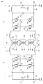
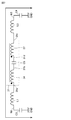
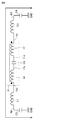
- FIG. It is another circuit diagram for demonstrating the resonance phenomenon which occurs in the bidirectional DC / DC converter shown in FIG. It is a circuit diagram for demonstrating the effect of Embodiment 1.
- FIG. It is another circuit diagram for demonstrating the effect of Embodiment 1.
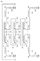
- FIG. It is a circuit diagram which shows the structure of the isolation transformer according to Embodiment 2. It is a figure which shows the isolation transformer according to Embodiment 3. It is a figure which shows the comparative example of Embodiment 3. It is a circuit diagram which shows the structure of the isolation transformer according to Embodiment 4.
- FIG. 1 is a circuit block diagram showing a configuration of a bidirectional DC / DC converter according to the first embodiment.
- the bidirectional DC / DC converter (power converter) is a DAB (Dual Active Bridge) system, and has DC terminals T1 to T4, current detectors 1, 7, power converters 2, 6, and insulation. It includes a transformer 3, an operation unit 8, and a control device 9.
- the DC terminals T1 and T2 are connected to the positive electrode and the negative electrode of the DC power supply 21 (first DC power supply), respectively.
- the DC terminals T3 and T4 are connected to the positive electrode and the negative electrode of the DC power supply 22 (second DC power supply), respectively.
- Each of the DC voltage VDC1 between the DC terminals T1 and T2 and the DC voltage VDC2 between the DC terminals T3 and T4 is detected by the control device 9.
- one of the DC power supplies 21 and 22 is a solar cell that outputs DC power, and the other is a battery (or capacitor) that stores DC power.
- Both DC power supplies 21 and 22 may be batteries (or capacitors).
- a load driven by DC power may be connected in parallel to at least one of the DC power supplies 21 and 22.
- the isolation transformer 3 includes first and second main windings 4 and 5, and first to fourth main terminals 3a to 3d. Black circles ( ⁇ ) are marked on the positive electrode side of the first and second main windings 4 and 5.
- the positive electrode terminal (first polar terminal) and the negative electrode terminal (second polar terminal) of the first main winding 4 are connected to the first and second main terminals 3a and 3b, respectively.
- the positive electrode terminal and the negative electrode terminal of the second main winding 5 are connected to the third and fourth main terminals 3c and 3d, respectively.
- FIG. 1 shows a case where the polar directions of the first and second main windings 4 and 5 are both upward.
- the number of turns of the first and second main windings 4 and 5 is the same.
- the AC voltage VAC1 When the AC voltage VAC1 is applied between the first and second main terminals 3a and 3b, the AC voltage VAC2 appears between the third and fourth main terminals 3c and 3d. On the contrary, when the AC voltage VAC2 is applied between the third and fourth main terminals 3c and 3d, the AC voltage VAC1 appears between the first and second main terminals 3a and 3b.
- the AC voltages VAC1 and VAC2 have the same polarity (that is, the same phase) and have the same amplitude.
- the power converter 2 (first power converter) is connected to the DC terminals 2a and 2b connected to the DC terminals T1 and T2, respectively, and to the first and second main terminals 3a and 3b of the isolation transformer 3, respectively. It includes AC terminals 2c and 2d and is controlled by the control device 9.
- the power converter 2 converts the DC voltage VDC1 applied from the DC power supply 21 to the DC terminals 2a and 2b into an AC voltage VAC1. Output between AC terminals 2c and 2d.
- the power converter 2 converts the AC voltage VAC1 applied between the AC terminals 2c and 2d into the DC voltage VDC1 and converts the DC voltage VDC1 into the DC terminal 2a. , Output between 2b.
- the power converter 6 (second power converter) is connected to the DC terminals 6a and 6b connected to the DC terminals T3 and T4, respectively, and to the third and fourth main terminals 3c and 3d of the isolation transformer 3, respectively. It includes AC terminals 6c and 6d and is controlled by the control device 9.
- the power converter 6 converts the AC voltage VAC2 given between the AC terminals 6c and 6d into the DC voltage VDC2 and outputs the AC voltage between the DC terminals 6a and 6b.
- the power converter 6 converts the DC voltage VDC2 given to the DC terminals 6a and 6b from the DC power supply 22 into the AC voltage VAC2 and outputs the DC voltage between the AC terminals 6c and 6d.
- the current detector 1 detects the current I1 flowing between the DC terminal T1 and the DC terminal 2a of the power converter 2, and outputs a signal I1f indicating the detected value to the control device 9.
- the current detector 7 detects the current I2 flowing between the DC terminal T3 and the DC terminal 6a of the power converter 6, and outputs a signal I2f indicating the detected value to the control device 9.
- the operation unit 8 has a plurality of buttons and a plurality of switches operated by the user of the bidirectional DC / DC converter, an image display unit for displaying various information, and the like. By operating the operation unit 8, the user turns on and off the power of the bidirectional DC / DC converter, and selects one of the first and second transmission modes. Is possible.
- the operation unit 8 outputs a signal or the like indicating the selected transmission mode to the control device 9.
- the control device 9 controls the entire bidirectional DC / DC converter based on the DC voltages VDC1 and VDC2, the DC currents I1 and I2 indicated by the output signals of the current detectors 1 and 7, the signals from the operation unit 8, and the like. ..
- the control device 9 sets the power converter 2 so that the DC current I2 becomes a predetermined reference current I2R (or the DC voltage VDC2 becomes a predetermined reference voltage VDC2R). , 6 are controlled respectively.
- the control device 9 sets the power converter 2 so that the DC current I1 becomes a predetermined reference current I1R (or the DC voltage VDC1 becomes a predetermined reference voltage VDC1R). , 6 are controlled respectively.
- the control device 9 includes a processing circuit 9a.
- the processing circuit 9a may be composed of digital electronic circuits such as an arithmetic processing device and a storage device, may be composed of analog electronic circuits such as a comparator, an operational amplifier, and a differential amplification circuit, and may be composed of digital electronic circuits and analog. It may be composed of both electronic circuits.
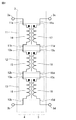
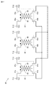
- FIG. 2 is a circuit diagram showing the configuration of the isolation transformer 3.
- the isolation transformer 3 includes a plurality of sub-insulation transformers 11 to 13.
- the sub-isolation transformers 11 to 13 constitute the first to Nth sub-isolation transformers.
- N is an integer greater than or equal to 2.
- the first sub-isolation transformer 11 includes an iron core (not shown), first and second sub-windings 14 and 17 wound around the iron core, and first to fourth sub-terminals 11a to 11d. Including. Black circles ( ⁇ ) are marked on the positive electrode side of the first and second auxiliary windings 14 and 17. The positive electrode terminal and the negative electrode terminal of the first auxiliary winding 14 are connected to the first and second auxiliary terminals 11a and 11b, respectively. The positive electrode terminal and the negative electrode terminal of the second auxiliary winding 17 are connected to the third and fourth auxiliary terminals 11c and 11d, respectively.
- FIG. 2 shows a case where the polar directions of the first and second sub-windings 14 and 17 are both upward.
- the number of turns of the first and second sub-windings 14 and 17 is the same.
- the second sub-isolation transformer 12 includes an iron core (not shown), first and second sub-windings 15 and 18 wound around the iron core, and first to fourth sub-terminals 12a to 12d. Including. Black circles ( ⁇ ) are marked on the positive electrode side of the first and second auxiliary windings 15 and 18. The positive electrode terminal and the negative electrode terminal of the first auxiliary winding 15 are connected to the first and second auxiliary terminals 12a and 12b, respectively. The positive electrode terminal and the negative electrode terminal of the second auxiliary winding 18 are connected to the third and fourth auxiliary terminals 12c and 12d, respectively.
- FIG. 2 shows a case where the polar directions of the first and second sub-windings 15 and 18 are both upward.
- the number of turns of the first and second sub-windings 15 and 18 is the same.
- the third sub-isolation transformer 13 has an iron core (not shown), first and second sub-windings 16 and 19 wound around the iron core, and first to fourth sub-terminals 13a to 13d. Including. Black circles ( ⁇ ) are marked on the positive electrode side of the first and second auxiliary windings 16 and 19. The positive electrode terminal and the negative electrode terminal of the first auxiliary winding 16 are connected to the first and second auxiliary terminals 13a and 13b, respectively. The positive electrode terminal and the negative electrode terminal of the second auxiliary winding 19 are connected to the third and fourth auxiliary terminals 13c and 13d, respectively.
- FIG. 2 shows a case where the polar directions of the first and second sub-windings 16 and 19 are both upward.
- the number of turns of the first and second sub-windings 16 and 19 is the same.
- the polarities of the three first sub-windings 14 to 16 are oriented in the same direction.
- the three first sub-windings 14 to 16 are connected in series between the first and second main terminals 3a and 3b of the isolation transformer 3 to form the first main winding 4. That is, the first sub-terminal 11a of the first sub-insulation transformer 11 is connected to the first main terminal 3a of the isolation transformer 3.
- the second sub-terminal 11b of the first sub-isolation transformer 11 is connected to the first sub-terminal 12a of the second sub-isolation transformer 12.
- the second sub-terminal 12b of the second sub-isolation transformer 12 is connected to the first sub-terminal 13a of the third sub-isolation transformer 13.
- the second sub-terminal 13b of the third sub-isolation transformer 13 is connected to the second main terminal 3b of the main isolation transformer 3.
- the polarities of the three second auxiliary windings 17 to 19 are oriented in the same direction.
- the three second sub-windings 17 to 19 are connected in series between the third and fourth main terminals 3c and 3d of the isolation transformer 3 to form the second main winding 5. That is, the third sub-terminal 11c of the first sub-insulation transformer 11 is connected to the third main terminal 3c of the isolation transformer 3.
- the fourth sub-terminal 11d of the first sub-isolation transformer 11 is connected to the third sub-terminal 12c of the second sub-isolation transformer 12.
- the fourth sub-terminal 12d of the second sub-isolation transformer 12 is connected to the third sub-terminal 13c of the third sub-isolation transformer 13.
- the fourth sub-terminal 13d of the third sub-isolation transformer 13 is connected to the fourth main terminal 3d of the main isolation transformer 3.
- the AC voltage VAC1 When the AC voltage VAC1 is applied between the first main terminal 3a and the second main terminal 3b, the AC voltage VAC2 appears between the third main terminal 3c and the fourth main terminal 3d.
- the AC voltage VAC2 When the AC voltage VAC2 is applied between the third main terminal 3c and the fourth main terminal 3d, the AC voltage VAC1 appears between the first main terminal 3a and the second main terminal 3b. Since the number of turns of the first main winding 4 and the number of turns of the second main winding 5 are the same, the amplitude of the AC voltage VAC1 and the amplitude of the AC voltage VAC2 are the same.
- the AC voltages VAC1 and VAC2 have the same polarity, and the phase of the AC voltage VAC1 and the phase of the AC voltage VAC2 are the same. become.
- FIG. 3 is a circuit diagram showing the configurations of the power converters 2 and 6.
- the power converter 2 includes capacitors C1, IGBT (Insulated Gate Bipolar Transistor) Q1 to Q4, diodes D1 to D4, and reactors L1 and L2.
- the capacitor C1 is connected between the DC terminals T1 and T2, and smoothes and stabilizes the DC voltage VDC1 between the DC terminals T1 and T2.
- the collectors of IGBT Q1 and Q2 are connected to the DC terminal T1, and their emitters are connected to the nodes N1 and N2 (first and second AC terminals), respectively.
- the collectors of IGBT Q3 and Q4 are connected to nodes N1 and N2, respectively, and their emitters are both connected to the DC terminal T2.
- Each of IGBT Q1 to Q4 is turned on and off by the control device 9.
- the reactor L1 is connected between the node N1 and the first main terminal 3a of the isolation transformer 3.
- the reactor L2 is connected between the node N2 and the second main terminal 3b of the isolation transformer 3.
- Each of the reactors L1 and L2 stores electromagnetic energy.
- the power converter 6 includes reactors L3 to L5, IGBT Q5 to Q8, diodes D5 to D8, and a capacitor C2.
- the reactor L3 is connected between the third main terminal 3c of the isolation transformer 3 and the node N4.
- the reactor L4 is connected between the fourth main terminal 3d of the isolation transformer 3 and the node N3.
- Each of the reactors L3 and L4 stores electromagnetic energy.
- the collectors of IGBT Q5 and Q6 are connected to each other, and their emitters are connected to nodes N3 and N4, respectively.
- the collectors of IGBT Q7 and Q8 are connected to nodes N3 and N4, respectively, and their emitters are both connected to the DC terminal T4.
- Each of IGBT Q5 to Q8 is turned on and off by the control device 9.
- the capacitor C2 is connected between the collectors of IGBT Q5 and Q6 and the DC terminal T4.
- the reactor L5 is connected between the collectors of the IGBT Q5 and Q6 and the DC terminal T3.
- the capacitor C2 and the reactor L5 form a low-pass filter.
- MOSFETs Metal Oxide Semiconductor Field Effect Transistors
- IGBTs IGBTs
- a capacitor may be connected in parallel to the IGBT as a zero voltage switching circuit that makes the collector-emitter voltage of the IGBT substantially zero voltage at the time of switching.
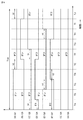
- FIG. 4 is a time chart for explaining the operation of the bidirectional DC / DC converters shown in FIGS. 1 to 3.
- FIG. 4 shows the operation in the first transmission mode in which the DC power is transmitted from the DC power supply 21 to the DC power supply 22.
- the DC power supply 22 is a battery.
- FIG. 4 (A) to (H) show on and off operations of IGBT Q1, Q3, Q2, Q4, Q5, Q7, Q6, and Q8, respectively.
- the switching cycle Tsw of the IGBT Q1 is divided into TA to TJ for 10 periods.
- the control device 9 alternately turns on the IGBT Q1, Q3, the IGBT Q4, Q2, and the IGBT Q5, Q7 in the switching cycle Tsw with the short-circuit prevention time td in between, and turns the IGBT Q6, Q8 off. Fix it.
- the first phase shift amount ⁇ 1 is from turning off the IGBT Q2 to turning on the IGBT Q4, and the second phase shift amount ⁇ 2 is from turning off the IGBT Q2 to turning on the IGBT Q7.
- the control device 9 adjusts the first phase shift amount ⁇ 1 and the second phase shift amount ⁇ 2 based on the transmission power amount.
- the second phase shift amount ⁇ 2 is set to a value larger than the first phase shift amount ⁇ 1. ..
- the second phase shift amount ⁇ 2 is set to the same value as the first phase shift amount ⁇ 1.
- the IGBT Q1 and Q4 are turned on, a current flows from the positive electrode of the DC power supply 21 to the negative electrode of the DC power supply 21 via the IGBT Q1, the reactor L1, the first main winding 4, the reactor L2, and the IGBT Q4, and the reactor L1 , L2 stores electromagnetic energy.
- the IGBT Q5 is turned on, and a current flows from the third main terminal 3c of the isolation transformer 3 to the third terminal 3c via the reactor L3, the diode D6, the IGBT Q5, the reactor L4, and the second main winding 5. Electromagnetic energy is stored in the reactors L3 and L4.
- the IGBT Q1 and Q4 are maintained in the ON state, the current flows in the same path as the period TB, and the electromagnetic energy is stored in the reactors L1 and L2. Further, the IGBT Q5 is turned off, and the reactor L3, the diode D6, the reactor L5, the DC power supply 22 (battery), the diode D7, the reactor L4, and the second main winding of the isolation transformer 3 are turned off from the third terminal 3c of the isolation transformer 3. A current flows through the third terminal 3c via 5, and the electromagnetic energy of the reactors L3 and L4 is released.
- the control device 9 sandwiches the IGBT Q6, Q8, the IGBT Q7, Q5, and the IGBT Q2, Q4 in the switching cycle Tsw with the short-circuit prevention time td.
- the IGBT Q1 and Q3 are fixed in the off state while being turned on alternately with.
- the reverse operation of the first transmission mode is performed, so the description thereof will not be repeated.
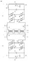
- FIG. 5 is a circuit diagram showing a main part of the comparative example of the first embodiment, and is a diagram to be compared with FIG. In FIG. 5, an isolation transformer 25 is used in this comparative example.
- the isolation transformer 25 includes first to fourth main terminals 25a to 25d, and a plurality of sub-isolation transformers 31 to 33.
- the plurality of sub-isolation transformers 31 to 33 are connected in series between the first and third main terminals 25a and 25c and the second and fourth main terminals 25b and 25d.
- the first sub-isolation transformer 31 includes an iron core (not shown), first and second sub-windings 34 and 37 wound around the iron core, and first to fourth sub-terminals 31a to 31d. And include. Black circles ( ⁇ ) are marked on the positive electrode side of the first and second auxiliary windings 34 and 37.
- the positive electrode terminal and the negative electrode terminal of the first auxiliary winding 34 are connected to the first and second auxiliary terminals 31a and 31b, respectively.
- the positive electrode terminal and the negative electrode terminal of the second auxiliary winding 37 are connected to the fourth and third auxiliary terminals 31d and 31c, respectively.
- FIG. 5 shows a case where the polar directions of the first and second sub-windings 34 and 37 are upward and downward, respectively.
- the number of turns of the first and second sub-windings 34 and 37 is the same.
- the second sub-isolation transformer 32 includes an iron core (not shown), first and second sub-windings 35 and 38 wound around the iron core, and first to fourth sub-terminals 32a to 32d. Including. Black circles ( ⁇ ) are marked on the positive electrode side of the first and second auxiliary windings 35 and 38.
- the positive electrode terminal and the negative electrode terminal of the first auxiliary winding 35 are connected to the first and second auxiliary terminals 32a and 32b, respectively.
- the positive electrode terminal and the negative electrode terminal of the second auxiliary winding 38 are connected to the fourth and third auxiliary terminals 32d and 32c, respectively.
- FIG. 5 shows a case where the polar directions of the first and second sub-windings 35 and 38 are upward and downward, respectively.
- the number of turns of the first and second sub-windings 35 and 38 is the same.
- the third sub-isolation transformer 33 has an iron core (not shown), first and second sub-windings 36 and 39 wound around the iron core, and first to fourth sub-terminals 33a to 33d. Including. Black circles ( ⁇ ) are marked on the positive electrode side of the first and second auxiliary windings 36 and 39.
- the positive electrode terminal and the negative electrode terminal of the first auxiliary winding 36 are connected to the first and second auxiliary terminals 33a and 33b, respectively.
- the positive electrode terminal and the negative electrode terminal of the second auxiliary winding 39 are connected to the fourth and third auxiliary terminals 33d and 33c, respectively.
- FIG. 5 shows a case where the polar directions of the first and second sub-windings 36 and 39 are upward and downward, respectively.
- the number of turns of the first and second sub-windings 36 and 39 is the same.
- the polarities of the three first auxiliary windings 34 to 36 are directed upward.
- the three first sub-windings 34 to 36 are connected in series between the first and second main terminals 25a and 25b of the isolation transformer 25 to form the first main winding 26.
- the polarities of the three second auxiliary windings 37 to 39 are directed downward.
- the three second sub-windings 37 to 39 are connected in series between the third and fourth main terminals 25c and 25d of the isolation transformer 25 to form the second main winding 27.
- the AC voltage VAC1 When the AC voltage VAC1 is applied between the first main terminal 25a and the second main terminal 25b, the AC voltage VAC2 appears between the third main terminal 25c and the fourth main terminal 25d.
- the AC voltage VAC2 When the AC voltage VAC2 is applied between the third main terminal 25c and the fourth main terminal 25d, the AC voltage VAC1 appears between the first main terminal 25a and the second main terminal 25b. Since the number of turns of the first main winding 26 and the number of turns of the second main winding 27 are the same, the amplitude of the AC voltage VAC1 and the amplitude of the AC voltage VAC2 are the same.
- the AC voltages VAC1 and VAC2 have opposite polarities, and the phase of the AC voltage VAC1 and the AC voltage VAC2 Is 180 degrees out of phase.
- Each of the sub-terminals 31b and 32a and the sub-terminals 31d and 32c to which the sub-isolation transformers 31 and 32 are connected is a high impedance connection point to which electrical components other than the sub-isolation transformers 31 and 32 are not connected.
- Each of the sub-terminals 32b and 33a and the sub-terminals 32d and 33c to which the sub-isolation transformers 32 and 33 are connected is a high impedance connection point to which electrical components other than the sub-isolation transformers 32 and 33 are not connected.
- the interphase capacitance between the first and second sub-windings of the sub-insulation transformers 31 to 33 is the isolation transformer 31. It becomes apparent at the connection points of to 33, and a resonance phenomenon occurs in the path passing through the first and second subwindings and the interphase capacitance between them.
- FIG. 6 is a circuit diagram showing the configuration of a bidirectional DC / DC converter including the isolation transformer 25 shown in FIG. 5, and is a diagram to be compared with FIG.
- the first to fourth main terminals 25a to 25d of the isolation transformer 25 are connected to one terminal of the reactors L1 to L4, respectively, and the other terminals of the reactors L1 to L4 are connected to the nodes N1 to N4, respectively.
- the ground capacitance C3 is connected between the DC terminal T2 and the ground voltage GND line (reference voltage line), and the ground capacitance C4 is connected between the DC terminal T4 and the ground voltage GND line.
- ground capacitances C3 and C4 assume a case where each of the DC terminals T2 and T4 is connected to the housing via a capacitor and the housing is grounded. However, this represents a state in which the DC terminals T2 and T4 are connected by a path having a low impedance in an electric circuit.
- Each of the DC terminals T2 and T4 may be directly connected to the housing without a capacitor, and the housing may be grounded. Further, each of the DC terminals T2 and T4 may be connected to a power system in which the ground potential is defined via an inverter circuit.
- the exciting inductance of 37 is excited.
- the interphase capacitance C5 is connected between the second and fourth sub-terminals 31b and 31d of the sub-insulated transformer 31, and the first sub-terminal 31a is the reactor L1, the node N1, and the ground.
- a resonance circuit is constructed by connecting to the ground voltage GND line via the capacitance C3 and connecting the third sub-terminal 31c to the ground voltage GND line via the reactor L3, the node N3, and the ground capacitance C4.
- a resonance phenomenon occurs between the exciting inductance of the first auxiliary winding 34, the interphase capacitance C5, and the exciting inductance of the second auxiliary winding 37.
- the equivalent circuit shown in FIG. 7 is simplified for the sake of simplicity of explanation, and the resonance circuit is not an independent sub-isolation transformer 31 alone, but is actually a resonance circuit as shown in FIG. Is configured. That is, in FIG. 8, the nodes N1 to N4 are connected to the ground voltage GND line via the ground capacitances C3a, C3b, C4a, and C4b, respectively.
- the interphase capacitance C6 is connected between the second and fourth sub-terminals 32b and 32d of the second sub-isolation transformer 32.
- the second sub-terminal 31b of the first sub-isolation transformer 31 is connected to the ground voltage GND line via the sub-windings 35 and 36, the reactor L2, and the ground capacitance C3b.
- the fourth sub-terminal 31d of the first sub-isolation transformer 31 is connected to the line of the ground voltage GND via the sub-windings 38 and 39, the reactor L4, and the ground capacitance C4b.
- a resonance phenomenon occurs between the exciting inductance of the first sub-windings 34 to 36, the interphase capacitances C5 and C6, and the exciting inductance of the second sub-windings 37 to 39.
- the exciting inductance of the sub-windings 34 to 39 of the sub-isolation transformers 31 to 33 is several hundred times or more higher than the inductance values of the reactors L1 to L4 that maintain the DC superimposition characteristics. It is always the case. Therefore, even if the current flowing due to the resonance phenomenon is small with respect to the main current of the circuit, voltage vibration that cannot be ignored occurs, which adversely affects the loss of the sub-isolation transformers 31 to 33.
- the exciting inductance of the first subwinding 34 and the exciting inductance of the second subwinding 37 have the same polarity, and the first and second subwindings 34 and 37 are excited.
- the excitation inductance of the sub-windings 34 and 37 is the sub-windings 34 and 37. It becomes four times the exciting inductance of each of.
- FIG. 9 is a circuit diagram showing a configuration of a resonance circuit generated by the bidirectional DC / DC converter shown in FIG. 3, which is compared with FIG. 7.
- an interphase capacitance C5 is connected between the second and fourth sub-terminals 11b and 11d of the sub-isolation transformer 11, and the first sub-terminal 11a is grounded via the reactor L1, the node N1, and the ground capacitance C3. It is connected to the line of the voltage GND, and the third sub-terminal 11c is connected to the line of the ground voltage GND via the reactor L3, the node N3, and the ground capacitance C4 to form a resonance circuit.
- the exciting inductance of the first sub-winding 14 and the exciting inductance of the second sub-winding 17 have opposite polarities and cancel each other out, so that the exciting inductance of the first sub-windings 14 and 17 Since the sum is 0, the resonance phenomenon does not occur.
- the sum of the exciting inductances of the first sub-windings 14 and 17 is the sum of the excitation inductances of the first sub-windings 14 and 17 when the number of turns of the first sub-winding 14 and the number of turns of the second sub-winding 17 are the same. Can be set to 0 to most effectively prevent the occurrence of the resonance phenomenon. However, even when the number of turns of the first sub-winding wheel 14 and the number of turns of the second sub-winding wheel 17 are different, the sum of the exciting inductances of the first sub-windings 14 and 17 is reduced to resonate. The occurrence of the phenomenon can be suppressed.
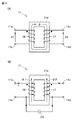
- FIG. 10 is a diagram showing the configuration and operation of the sub-isolation transformer 11.
- (A) shows a normal transformation operation
- (B) shows an operation when a current flows through the interphase capacitance C5.
- the auxiliary windings 14 and 17 are wound around the annular iron core 11e.
- the auxiliary windings 14 and 17 share a magnetic flux ⁇ passing through the iron core 11e.
- V1 n1 (d ⁇ / dt)
- V2 n2 (d ⁇ / dt). It becomes.
- n1 n2.
- V1 and V2 have the same polarity and have the same phase and the same amplitude.
- FIG. 10B when a current I flows from the first sub terminal 11a to the third sub terminal 11c via the first sub winding 14, the interphase capacitance C5, and the second sub winding 11c,
- the current I flowing through the first auxiliary winding 14 generates a magnetic flux ⁇ 1 in the iron core 11e
- the current I flowing through the second auxiliary winding 17 generates a magnetic flux ⁇ 2 in the iron core 11e.
- the magnetic flux ⁇ 1 and the magnetic flux ⁇ 2 are generated in opposite directions in the iron core 11e, and the magnetic flux ⁇ 1 and the magnetic flux ⁇ 2 cancel each other out.
- the isolation transformer 3 since the plurality of sub-isolation transformers 11 to 13 are connected in series to form the isolation transformer 3, it is possible to prevent the increase in volume and the concentration of weight in the isolation transformer 3. It is possible to mount on a substrate, improve the assembling property, improve the heat dissipation by dispersing the heat source, and realize the cost reduction by using a general-purpose sub-isolation transformer which has a large distribution volume and is easily available.
- the polar directions of the sub-windings 14 to 19 of the sub-isolation transformers 11 to 13 are the same, for example, the first main terminal 3a to the first sub-winding wheel 14, the interphase capacitance C5, and the second When the current I flows through the third main terminal 3b via the sub winding 17, the sum of the exciting inductances La and Lb of the first and second sub windings 14 and 17 becomes 0. Therefore, it is possible to prevent the resonance phenomenon from occurring.
- the isolation transformer 3 is provided in the DAB type bidirectional DC / DC converter, but the present invention is not limited to this, and the isolation transformer 3 is provided in another high frequency circuit. Needless to say, the same effect can be obtained even if this is the case.
- the DAB type bidirectional DC / DC converter including an isolation transformer 3 including two main windings 4 and 5 and two bridge circuits (Q1 to Q4 and Q5 to Q8) is provided.
- each DC terminal includes an isolation transformer including three main windings, three bridge circuits connected to each of the three main windings, and three DC terminal pairs connected to each of the three bridge circuits.
- TAB Triple Active Bridge
- the isolation transformer is divided into multiple sub-isolation transformers, and the orientation of the polarity of all sub-windings. May be aligned. Also in this case, it is possible to prevent the occurrence of the resonance phenomenon in each sub-isolation transformer.
- FIG. 11 is a circuit diagram showing the configuration of the isolation transformer 40 according to the second embodiment.
- the isolation transformer 40 is a three-phase transformer having a YY type connection, and includes first to sixth main terminals T11 to T16 and first to third sub-isolation transformers 41 to 43. ..
- the first to third main terminals T11 to T13 receive the three-phase AC voltages Vu1, Vv1, and Vw1.
- the three-phase AC voltages Vu2, Vv2, and Vw2 are output to the fourth to sixth main terminals T14 to T16.
- the first sub-isolation transformer 41 includes an iron core (not shown), first and second sub-windings 44 and 47 wound around the iron core, and first to fourth sub-terminals 41a to 41d. Including. Black circles ( ⁇ ) are marked on the positive electrode side of the first and second auxiliary windings 44 and 47.
- the positive electrode terminal and the negative electrode terminal of the first auxiliary winding 44 are connected to the first and second auxiliary terminals 41a and 41b, respectively.
- the positive electrode terminal and the negative electrode terminal of the second auxiliary winding 47 are connected to the third and fourth auxiliary terminals 41c and 41d, respectively.
- FIG. 11 shows a case where the polar directions of the first and second sub-windings 44 and 47 are both upward.
- the number of turns of the first and second sub-windings 44 and 47 is the same.
- the second sub-isolation transformer 42 includes an iron core (not shown), first and second sub-windings 45 and 48 wound around the iron core, and first to fourth sub-terminals 42a to 42d. Including. Black circles ( ⁇ ) are marked on the positive side of the first and second auxiliary windings 45 and 48.
- the positive electrode terminal and the negative electrode terminal of the first auxiliary winding 45 are connected to the first and second auxiliary terminals 42a and 42b, respectively.
- the positive electrode terminal and the negative electrode terminal of the second auxiliary winding 48 are connected to the third and fourth auxiliary terminals 42c and 42d, respectively.
- FIG. 11 shows a case where the polar directions of the first and second sub-windings 45 and 48 are both upward.
- the number of turns of the first and second sub-windings 45 and 48 is the same.
- the third sub-isolation transformer 43 includes an iron core (not shown), first and second sub-windings 46 and 49 wound around the iron core, and first to fourth sub-terminals 43a to 43d. Including. Black circles ( ⁇ ) are marked on the positive electrode side of the first and second auxiliary windings 46 and 49.
- the positive electrode terminal and the negative electrode terminal of the first auxiliary winding 46 are connected to the first and second auxiliary terminals 43a and 43b, respectively.
- the positive electrode terminal and the negative electrode terminal of the second auxiliary winding 49 are connected to the third and fourth auxiliary terminals 43c and 43d, respectively.
- FIG. 11 shows a case where the polar directions of the first and second sub-windings 46 and 49 are both upward.
- the number of turns of the first and second sub-windings 46 and 49 is the same.
- the first sub-terminals 41a, 42a, 43a of the sub-isolation transformers 41, 42, 43 are connected to the first to third main terminals T11 to T13, respectively.
- the third sub-terminals 41c, 42c, 43c of the sub-isolation transformers 41, 42, 43 are connected to the fourth to sixth main terminals T14 to T16, respectively.
- the second sub-terminals 41b, 42b, 43b of the sub-isolation transformers 41, 42, 43 are connected to each other.
- the fourth sub-terminals 41d, 42d, 43d of the sub-isolation transformers 41, 42, 43 are connected to each other.
- the interphase capacitance between the first main terminal T11 to the first subwinding 44, the subwinding 44, 47, and the second subwinding 47 to the fourth main terminal T14 Even when a current flows, the sum of the exciting inductances of the sub-windings 44 and 47 becomes 0 as described with reference to FIG. 9, so that the occurrence of the resonance phenomenon in the sub-isolation transformer 41 can be suppressed. Similarly, the occurrence of the resonance phenomenon in each of the sub-isolation transformers 42 and 43 can be suppressed.
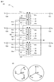
- FIG. 12 is a diagram showing an isolation transformer 50 according to the third embodiment.
- the isolation transformer 50 is a three-phase transformer having a Y-staggered connection, and includes first to sixth main terminals T21 to T26 and first to third sub-isolation transformers 51 to 53.
- the first to third main terminals T21 to T23 receive the three-phase AC voltages Vu, Vv, and Vw.
- Three-phase AC voltages Va, Vb, and Vc are output to the fourth to sixth main terminals T14 to T16.
- the first sub-isolation transformer 51 includes an iron core (not shown), first to third sub windings 54, 57, 60 wound around the iron core, and first to sixth sub terminals 51a to 51f. And include. Black circles ( ⁇ ) are marked on the positive electrode side of the first to third auxiliary windings 54, 57, 60.
- the positive electrode terminal and the negative electrode terminal of the first auxiliary winding 54 are connected to the first and second auxiliary terminals 51a and 51b, respectively.
- the positive electrode terminal and the negative electrode terminal of the second auxiliary winding 57 are connected to the third and fourth auxiliary terminals 51c and 51d, respectively.
- the positive electrode terminal and the negative electrode terminal of the third auxiliary winding 60 are connected to the fifth and sixth auxiliary terminals 51e and 51f, respectively.
- FIG. 12A shows a case where the polar directions of the first to third sub-windings 54, 57, 60 are both upward.
- the ratio of the number of turns of the first to third auxiliary windings 54, 57, 60 is 2: 1: 1.
- the second sub-isolation transformer 52 includes an iron core (not shown), first to third sub windings 55, 58, 61 wound around the iron core, and first to sixth sub terminals 52a to 52f. And include. Black circles ( ⁇ ) are marked on the positive electrode side of the first to third auxiliary windings 55, 58, 61.
- the positive electrode terminal and the negative electrode terminal of the first auxiliary winding 55 are connected to the first and second auxiliary terminals 52a and 52b, respectively.
- the positive electrode terminal and the negative electrode terminal of the second auxiliary winding 58 are connected to the third and fourth auxiliary terminals 52c and 52d, respectively.
- the positive electrode terminal and the negative electrode terminal of the third auxiliary winding 61 are connected to the fifth and sixth auxiliary terminals 52e and 52f, respectively.
- FIG. 12A shows a case where the polar directions of the first to third auxiliary windings 55, 58, and 61 are both upward.
- the ratio of the number of turns of the first to third auxiliary windings 55, 58, 61 is 2: 1: 1.
- the third sub-isolation transformer 53 includes an iron core (not shown), first to third sub windings 56, 59, 62 wound around the iron core, and first to sixth sub terminals 53a to 53f. And include. Black circles ( ⁇ ) are marked on the positive electrode side of the first to third auxiliary windings 56, 59, 62.
- the positive electrode terminal and the negative electrode terminal of the first auxiliary winding 56 are connected to the first and second auxiliary terminals 53a and 53b, respectively.
- the positive electrode terminal and the negative electrode terminal of the second auxiliary winding 59 are connected to the third and fourth auxiliary terminals 53c and 53d, respectively.
- the positive electrode terminal and the negative electrode terminal of the third auxiliary winding 62 are connected to the fifth and sixth auxiliary terminals 53e and 53f, respectively.
- FIG. 12A shows a case where the polar directions of the first to third sub-windings 56, 59, 62 are both upward.
- the ratio of the number of turns of the first to third auxiliary windings 56, 59, 62 is 2: 1: 1.
- the first sub-terminals 51a, 52a, 53a of the sub-isolation transformers 51, 52, 53 are connected to the first to third main terminals T21 to T23, respectively.
- the third sub-terminals 51c, 52c, 53c of the sub-isolation transformers 51, 52, 53 are connected to the fourth to sixth main terminals T24 to T26, respectively.
- the second sub-terminals 51b, 52b, 53b of the sub-isolation transformers 51, 52, 53 are connected to the first neutral point M1.
- the fifth sub-terminals 51e, 52e, 53e of the sub-isolation transformers 51, 52, 53 are connected to the second neutral point M2.
- the sixth sub-terminals 51f, 52f, 53f of the sub-isolation transformers 51, 52, 53 are connected to the fourth sub-terminals 52d, 53d, 51d of the sub-isolation transformers 52, 53, 51, respectively.
- the phases of the three-phase AC voltages Vu, Vv, and Vw are shifted by 120 degrees, and the phases of the three-phase AC voltages Va, Vb, and Vc are also shifted by 120 degrees.
- the phases of the three-phase AC voltages Va, Vb, and Vc are 30 degrees ahead of the phases of the three-phase AC voltages Vu, Vv, and Vw, respectively.
- the interphase capacitance between the first main terminal T21 and the first sub-winding 51 and the sub-windings 54 and 60, and the interphase capacitance between the third sub-winding 60 and the sub-windings 60 and 57 is 0 as described with reference to FIG. Therefore, the occurrence of the resonance phenomenon in the sub-insulation transformer 51 can be suppressed. Similarly, the occurrence of the resonance phenomenon in each of the sub-isolation transformers 52 and 53 can be suppressed.
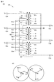
- FIG. 13 is a diagram showing an isolation transformer 65 as a comparative example of the third embodiment, and is a diagram to be compared with FIG.
- (A) shows the configuration of the isolation transformer 65
- (B) shows the operation of the isolation transformer 65.
- the difference between the isolation transformer 65 and the isolation transformer 50 of FIG. 12 is that the first sub-terminals 51a, 52a, 53a of the sub-insulation transformers 51, 52, 53 are connected to the first neutral point M1 and the sub-isolation transformer is connected.
- the point is that the second sub-terminals 51b, 52b, 53b of 51, 52, and 53 are connected to the first to third main terminals T21, T22, and T23, respectively.
- the phases of the three-phase AC voltages Vw, Vv, and Vu are shifted by 120 degrees, and the phases of the three-phase AC voltages Vc, Vb, and Va are also shifted by 120 degrees.
- the phases of the three-phase AC voltages Vb, Vc, and Va are delayed by 30 degrees from the phases of the three-phase AC voltages Vu, Vv, and Vw, respectively.
- the interphase capacitance between the first main terminal T21 and the sub-windings 54, 60 the interphase capacitance between the sub-windings 60, the sub-windings 60, 57, and the fourth via the sub-windings 57.
- the exciting inductances of the sub-windings 60 and 57 have the same polarity, and the sum of the exciting inductances of the sub-windings 60 and 57 becomes a large value.
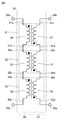
- FIG. 14 is a circuit diagram showing the configuration of the isolation transformer 70 according to the fourth embodiment, and is a diagram to be compared with FIG.
- the difference between the isolation transformer 70 and the isolation transformer 3 of FIG. 2 is that the first to fourth main terminals 3a to 3d are replaced by the first to fifth main terminals 70a to 70e, and the fourth sub-isolation transformer 71 Is added.
- the fourth sub-isolation transformer 71 includes an iron core (not shown), first and second sub-windings 72 and 73 wound around the iron core, and first to fourth sub-terminals 71a to 71d. Including. Black circles ( ⁇ ) are marked on the positive electrode side of the first and second auxiliary windings 72 and 73.
- the positive electrode terminal and the negative electrode terminal of the first auxiliary winding 72 are connected to the first and second auxiliary terminals 71a and 71b, respectively.
- the positive electrode terminal and the negative electrode terminal of the second auxiliary winding 73 are connected to the third and fourth auxiliary terminals 71c and 71d, respectively.
- FIG. 14 shows a case where the polar directions of the first and second auxiliary windings 72 and 73 are upward.
- the number of turns of the first and second sub-windings 72 and 73 is the same.
- the first and third sub-terminals 71a and 71c of the fourth sub-isolation transformer 71 are connected to the second and fourth sub-terminals 13c and 13d of the third sub-isolation transformer 13, respectively.
- the second and fourth sub-terminals 71b and 71d of the fourth sub-isolation transformer 71 are connected to the third and fifth main terminals 70c and 70e, respectively.
- the first and third sub-terminals 11a and 11c of the first sub-isolation transformer 11 are connected to the first and fourth main terminals 70a and 70d, respectively.
- the second main terminal 70b is connected to the second sub terminal 12b of the second sub-isolation transformer 12.
- the polarities of the eight sub-windings 11-13, 17-19, 72, 73 are oriented in the same direction.
- the sub-windings 11 and 12 form the first main winding
- the sub-windings 13 and 72 form the second main winding
- the sub-windings 17-19 and 73 form the third main winding.
- the polarities of the first to third main windings are oriented in the same direction.
- the interphase capacitance between the first main terminal 70a and the first subwinding 14, the subwinding 14, and 17 and the second subwinding 17 to the fourth main terminal 70d Even when a current flows, as described with reference to FIG. 9, the sum of the exciting inductances of the sub-windings 14 and 17 becomes 0, so that the occurrence of the resonance phenomenon in the sub-isolation transformer 11 can be prevented. Similarly, it is possible to prevent the occurrence of a resonance phenomenon in each of the sub-isolation transformers 12, 13, and 71.
- the same effect as in the first embodiment can be obtained.
- the above embodiments 1 to 4 may be combined as appropriate.
- the same effect can be obtained by replacing each of the sub-insulation transformers 41 to 43 in FIG. 11 with the isolation transformer 3 in FIG.
- T1 to T4 DC terminals 1,7 current detectors, 2,6 power converters, 3,25,40,50,65,70 isolation transformers, 4,5,26,27 main windings, 8 operation units, 9 Control device, 9a processing device, 11-13, 31-33, 41-43, 51-53, 71 sub-isolation transformer, 11e iron core, 14-19, 34-39, 44-49, 54-62, 72, 73 Auxiliary windings, 21 and 22, DC power supplies, C1, C2 capacitors, Q1 to Q8 IGBTs, D1 to D8 diodes, L1 to L5 reactors, C3, C3a, C3b, C4, C4a, C4b ground capacitance, C5, C6 interphase capacitance.
Landscapes
- Engineering & Computer Science (AREA)
- Power Engineering (AREA)
- Physics & Mathematics (AREA)
- Electromagnetism (AREA)
- Dc-Dc Converters (AREA)
- Rectifiers (AREA)
Abstract
Description
図1は、実施の形態1に従う双方向DC/DCコンバータの構成を示す回路ブロック図である。図1において、この双方向DC/DCコンバータ(電力変換装置)は、DAB(Dual Active Bridge)方式であって、直流端子T1~T4、電流検出器1,7、電力変換器2,6、絶縁トランス3、操作部8、および制御装置9を備える。
図11は、実施の形態2に従う絶縁トランス40の構成を示す回路図である。図11において、この絶縁トランス40は、Y-Y形結線を有する三相トランスであって、第1~第6の主端子T11~T16および第1~第3の副絶縁トランス41~43を備える。第1~第3の主端子T11~T13は、三相交流電圧Vu1,Vv1,Vw1を受ける。第4~第6の主端子T14~T16には、三相交流電圧Vu2,Vv2,Vw2が出力される。
実施の形態3.
図12は、実施の形態3に従う絶縁トランス50を示す図である。図12において、(A)は絶縁トランス50の構成を示し、(B)は絶縁トランス50の動作を示している。この絶縁トランス50は、Y-千鳥形結線を有する三相トランスであって、第1~第6の主端子T21~T26および第1~第3の副絶縁トランス51~53を備える。第1~第3の主端子T21~T23は、三相交流電圧Vu,Vv,Vwを受ける。第4~第6の主端子T14~T16には、三相交流電圧Va,Vb,Vcが出力される。
図13は、実施の形態3の比較例となる絶縁トランス65を示す図であって、図12と対比される図である。図13において、(A)は絶縁トランス65の構成を示し、(B)は絶縁トランス65の動作を示している。
図14は、実施の形態4に従う絶縁トランス70の構成を示す回路図であって、図2と対比される図である。この絶縁トランス70が図2の絶縁トランス3と異なる点は、第1~第4の主端子3a~3dが第1~第5の主端子70a~70eで置換され、第4の副絶縁トランス71が追加されている点である。
なお、上記実施の形態1~4を適宜組み合わせてもよいことは言うまでもない。たとえば、図11の副絶縁トランス41~43の各々を図2の絶縁トランス3で置換しても同じ効果が得られる。
Claims (10)
- 互いに電気的に結合された第1~第Nの副絶縁トランスを備え、Nは2以上の整数であり、
前記第1~第Nの副絶縁トランスの各々は、
第1および第2の副巻線と、
それぞれ前記第1の副巻線の第1極性端子および第2極性端子に接続された第1および第2の副端子と、
それぞれ前記第2の副巻線の第1極性端子および第2極性端子に接続された第3および第4の副端子とを含み、
前記第1および第2の副巻線の極性の方向は同じであり、
前記第1の副端子から前記第1の副巻線、前記第1および第2の副巻線間の相間容量、および前記第2の副巻線を介して前記第3の副端子に電流が流れた場合には、前記第1の副巻線の励磁インダクタンスと前記第2の副巻線の励磁インダクタンスとが逆極性になるように構成されている、絶縁トランス。 - 前記第1および第2の副巻線の巻数は同じである、請求項1に記載の絶縁トランス。
- 前記絶縁トランスは、
第1および第2の主巻線と、
それぞれ前記第1の主巻線の第1極性端子および第2極性端子に接続された第1および第2の主端子と、
それぞれ前記第2の主巻線の第1極性端子および第2極性端子に接続された第3および第4の主端子とを備え、
前記第1および第2の主巻線の方向は同じであり、
前記第1~第Nの副絶縁トランスに含まれるN個の前記第1の副巻線の極性の方向は同じであり、N個の前記第1の副巻線は前記第1および第2の主端子間に直列接続されて前記第1の主巻線を構成し、
前記第1~第Nの副絶縁トランスに含まれるN個の前記第2の副巻線の極性の方向は同じであり、N個の前記第2の副巻線は前記第3および第4の主端子間に直列接続されて前記第2の主巻線を構成している、請求項1に記載の絶縁トランス。 - Nは3であり、
前記絶縁トランスは、Y-Y形結線を有する三相トランスであって、
第1~第3の副絶縁トランスと、
三相交流電圧を受ける第1~第3の主端子と、
三相交流電圧を出力する第4~第6の主端子とを備え、
前記第1~第3の副絶縁トランスの前記第1の副端子はそれぞれ前記第1~第3の主端子に接続され、
前記第1~第3の副絶縁トランスの前記第2の副端子は互いに接続され、
前記第1~第3の副絶縁トランスの前記第3の副端子はそれぞれ前記第3~第5の主端子に接続され、
前記第1~第3の副絶縁トランスの前記第4の副端子は互いに接続されている、請求項1に記載の絶縁トランス。 - 前記第1~第Nの副絶縁トランスの各々は、
第3の副巻線と、
それぞれ前記第3の副巻線の第1極性端子および第2極性端子に接続された第5および第6の副端子とをさらに含み、
前記第1~第3の副巻線の極性の方向は同じであり、
前記第1の副端子から前記第1の副巻線、前記第1および第3の副巻線間の相間容量、前記第3の副巻線、前記第2および第3の副巻線間の相間容量、および前記第2の副巻線を介して前記第3の副端子に電流が流れた場合には、前記第1の副巻線の励磁インダクタンスと、前記第2および第3の副巻線の励磁インダクタンスとが逆極性になるように構成されている、請求項1に記載の絶縁トランス。 - 前記第1の副巻線の巻数は前記第2の副巻線の巻数の2倍であり、
前記第2および第3の副巻線の巻数は同じである、請求項5に記載の絶縁トランス。 - Nは3であり、
前記絶縁トランスは、Y-千鳥形結線を有する三相トランスであって、
第1~第3の副絶縁トランスと、
三相交流電圧を受ける第1~第3の主端子と、
三相交流電圧を出力する第4~第6の主端子とを備え、
前記第1~第3の副絶縁トランスの前記第1の副端子はそれぞれ前記第1~第3の主端子に接続され、
前記第1~第3の副絶縁トランスの前記第2の副端子は互いに接続され、
前記第1~第3の副絶縁トランスの前記第3の副端子はそれぞれ前記第4~第6の主端子に接続され、
前記第1~第3の副絶縁トランスの前記第5の副端子は互いに接続され、
前記第1~第3の副絶縁トランスの前記第6の副端子はそれぞれ前記第2、第3、第1の副絶縁トランスの第4の副端子に接続されている、請求項5に記載の絶縁トランス。 - 請求項1に記載の絶縁トランスと、
第1の直流電源から供給される直流電力を交流電力に変換する第1の電力変換器と、
前記第1の交流電源から前記絶縁トランスを介して供給される交流電力を直流電力に変換して第2の直流電源に供給する第2の電力変換器とを備え、
前記第1の電力変換器から前記第1の副端子、前記第1の副巻線、前記第1および第2の副巻線間の相間容量、前記第2の副巻線、前記第3の副端子、前記第2の電力変換器、および基準電圧のラインを介して前記第1の電力変換器に至る経路に電流が流れた場合には、前記第1の副巻線の励磁インダクタンスと前記第2の副巻線の励磁インダクタンスとが逆極性になるように構成されている、電力変換装置。 - 前記第1の電力変換器は、
直流電圧を受ける第1および第2の直流端子と、
交流電圧を受ける第1および第2の交流端子と、
前記第1の直流端子と前記第1および第2の交流端子との間にそれぞれ接続された第1および第2のトランジスタと、
前記第1および第2の交流端子と前記第2の直流端子との間にそれぞれ接続された第3および第4のトランジスタと、
それぞれ前記第1~第4のトランジスタに逆並列に接続された第1~第4のダイオードとを含み、
前記第2の電力変換器は、
直流電圧を受ける第3および第4の直流端子と、
交流電圧を受ける第3および第4の交流端子と、
前記第3の直流端子と前記第3および第4の交流端子との間にそれぞれ接続された第5および第6のトランジスタと、
前記第3および第4の交流端子と前記第4の直流端子との間にそれぞれ接続された第7および第8のトランジスタと、
それぞれ前記第5~第8のトランジスタに逆並列に接続された第5~第8のダイオードとを含み、
前記絶縁トランスは、
第1および第2の主巻線と、
それぞれ前記第1の主巻線の第1極性端子および第2極性端子に接続された第1および第2の主端子と、
それぞれ前記第2の主巻線の第1極性端子および第2極性端子に接続された第3および第4の主端子とを備え、
前記第1および第2の主巻線の極性の方向は同じであり、
前記第1および第2の交流端子はそれぞれ前記第1および第2の主端子に結合され、
前記第3および第4の交流端子はそれぞれ前記第4および第3の主端子に結合されている、請求項8に記載の電力変換装置。 - 前記第1の電力変換器は、
前記第1の交流端子と前記第1の主端子との間に接続された第1のリアクトルと、
前記第2の交流端子と前記第2の主端子との間に接続された第2のリアクトルとをさらに含み、
前記第2の電力変換器は、
前記第3の交流端子と前記第4の主端子との間に接続された第3のリアクトルと、
前記第4の交流端子と前記第3の主端子との間に接続された第4のリアクトルとをさらに含み、
前記電力変換装置は、前記第1~第8のトランジスタを制御する制御装置をさらに備え、
前記制御装置は、前記第1の直流電源から前記第2の直流電源に直流電力を供給する場合には、前記第1および第3のトランジスタを交互にオンさせ、前記第4および第2のトランジスタを交互にオンさせ、前記第5および第7のトランジスタを交互にオンさせ、第6および第8のトランジスタをオフ状態に維持する、請求項9に記載の電力変換装置。
Priority Applications (5)
| Application Number | Priority Date | Filing Date | Title |
|---|---|---|---|
| JP2020540509A JP6840296B1 (ja) | 2019-12-05 | 2019-12-05 | 絶縁トランスおよびそれを備えた電力変換装置 |
| PCT/JP2019/047679 WO2021111601A1 (ja) | 2019-12-05 | 2019-12-05 | 絶縁トランスおよびそれを備えた電力変換装置 |
| US17/766,534 US12170487B2 (en) | 2019-12-05 | 2019-12-05 | Insulating transformer and power conversion device equipped with same |
| EP19954762.1A EP4071992A4 (en) | 2019-12-05 | 2019-12-05 | ISOLATION TRANSFORMER AND POWER CONVERSION DEVICE EQUIPPED THEREOF |
| CN201980102645.7A CN114762234B (zh) | 2019-12-05 | 2019-12-05 | 绝缘变压器以及具备其的电力变换装置 |
Applications Claiming Priority (1)
| Application Number | Priority Date | Filing Date | Title |
|---|---|---|---|
| PCT/JP2019/047679 WO2021111601A1 (ja) | 2019-12-05 | 2019-12-05 | 絶縁トランスおよびそれを備えた電力変換装置 |
Publications (1)
| Publication Number | Publication Date |
|---|---|
| WO2021111601A1 true WO2021111601A1 (ja) | 2021-06-10 |
Family
ID=74845252
Family Applications (1)
| Application Number | Title | Priority Date | Filing Date |
|---|---|---|---|
| PCT/JP2019/047679 Ceased WO2021111601A1 (ja) | 2019-12-05 | 2019-12-05 | 絶縁トランスおよびそれを備えた電力変換装置 |
Country Status (5)
| Country | Link |
|---|---|
| US (1) | US12170487B2 (ja) |
| EP (1) | EP4071992A4 (ja) |
| JP (1) | JP6840296B1 (ja) |
| CN (1) | CN114762234B (ja) |
| WO (1) | WO2021111601A1 (ja) |
Families Citing this family (1)
| Publication number | Priority date | Publication date | Assignee | Title |
|---|---|---|---|---|
| CN113241952A (zh) * | 2021-06-25 | 2021-08-10 | 阳光电源股份有限公司 | 一种隔离式双向变换器及其控制方法 |
Citations (7)
| Publication number | Priority date | Publication date | Assignee | Title |
|---|---|---|---|---|
| JPH05268767A (ja) * | 1992-03-17 | 1993-10-15 | Toyota Autom Loom Works Ltd | プッシュプルdc−dcコンバータ |
| WO2006046419A1 (ja) * | 2004-10-28 | 2006-05-04 | Minebea Co., Ltd. | 多灯式放電灯点灯装置 |
| JP2009124861A (ja) * | 2007-11-15 | 2009-06-04 | Cosel Co Ltd | スイッチング電源装置 |
| JP2015142419A (ja) * | 2014-01-28 | 2015-08-03 | 新電元工業株式会社 | 複合トランス及び共振コンバータ |
| JP2017216437A (ja) * | 2016-05-03 | 2017-12-07 | トヨタ モーター エンジニアリング アンド マニュファクチャリング ノース アメリカ,インコーポレイティド | 統合型インダクタ |
| WO2018016106A1 (ja) | 2016-07-19 | 2018-01-25 | 三菱電機株式会社 | Dc/dcコンバータ |
| JP2019079992A (ja) * | 2017-10-26 | 2019-05-23 | 富士電機株式会社 | トランス |
Family Cites Families (32)
| Publication number | Priority date | Publication date | Assignee | Title |
|---|---|---|---|---|
| US2428586A (en) * | 1943-07-20 | 1947-10-07 | Westinghouse Electric Corp | Vapor-electric device |
| US3210648A (en) * | 1962-07-09 | 1965-10-05 | Westinghouse Electric Corp | Regulating and current limiting transformer system |
| US3210704A (en) * | 1962-12-27 | 1965-10-05 | Westinghouse Electric Corp | Electrical inductive apparatus having interleaved windings |
| US3745440A (en) * | 1972-02-28 | 1973-07-10 | Litton Systems Inc | Electrical inverter-rectifier circuit and inductor apparatus therefor |
| US4912372A (en) * | 1988-11-28 | 1990-03-27 | Multi Electric Mfg. Co. | Power circuit for series connected loads |
| US5422765A (en) * | 1989-01-24 | 1995-06-06 | Fanuc Ltd. | Inverter device attenuating in-phase harmonic components of an oscillating output signal |
| JPH0365053A (ja) | 1989-04-04 | 1991-03-20 | Hitachi Metals Ltd | スイッチング電源 |
| US5598327A (en) * | 1990-11-30 | 1997-01-28 | Burr-Brown Corporation | Planar transformer assembly including non-overlapping primary and secondary windings surrounding a common magnetic flux path area |
| JP2606997Y2 (ja) | 1993-09-28 | 2001-02-19 | デンセイ・ラムダ株式会社 | スイッチング電源装置 |
| JPH08168249A (ja) * | 1994-10-11 | 1996-06-25 | Sony Corp | 電流共振形スイッチング電源回路 |
| US5754413A (en) * | 1996-02-23 | 1998-05-19 | Lucent Technologies Inc. | Reduced voltage stress asymmetrical DC-to-DC converter using first and second transformers having differing turns ratios |
| US6888709B2 (en) * | 2002-05-03 | 2005-05-03 | Applied Energy Llc | Electromagnetic transient voltage surge suppression system |
| US7573000B2 (en) * | 2003-07-11 | 2009-08-11 | Lincoln Global, Inc. | Power source for plasma device |
| EP1671521B1 (en) * | 2003-10-06 | 2010-02-17 | Microsemi Corporation | A current sharing scheme and device for multiple ccf lamp operation |
| US7932693B2 (en) * | 2005-07-07 | 2011-04-26 | Eaton Corporation | System and method of controlling power to a non-motor load |
| WO2007143605A2 (en) * | 2006-06-05 | 2007-12-13 | Daniel Princinsky | Electromagnetic noise suppression system for wye power distribution |
| EP2416486B1 (en) * | 2009-03-30 | 2018-05-30 | Hitachi, Ltd. | Power conversion device |
| CN103329420B (zh) * | 2011-01-26 | 2015-12-02 | 株式会社村田制作所 | 开关电源电路 |
| WO2012101905A1 (ja) * | 2011-01-26 | 2012-08-02 | 株式会社村田製作所 | スイッチング電源装置 |
| JP5824862B2 (ja) * | 2011-05-11 | 2015-12-02 | 株式会社リコー | 高電圧インバータ装置 |
| CN103595367B (zh) * | 2013-11-07 | 2017-03-08 | 华为技术有限公司 | 一种磁集成器件及一种功率转换电路 |
| US10707747B2 (en) * | 2015-07-21 | 2020-07-07 | Christopher Donovan Davidson | Single stage isolated AC/DC power factor corrected converter |
| US20190348213A1 (en) * | 2017-04-17 | 2019-11-14 | Mitsubishi Electric Corporation | Planar transformer, laser diode-driving power supply, and laser machining apparatus |
| US10672553B2 (en) * | 2017-05-10 | 2020-06-02 | Raytheon Company | High voltage high frequency transformer |
| JP6461439B1 (ja) * | 2017-08-23 | 2019-01-30 | 三菱電機株式会社 | Dc/dcコンバータ |
| KR102211454B1 (ko) * | 2017-08-31 | 2021-02-04 | 한국전자기술연구원 | 절연형 dc-dc 컨버터 및 그 구동방법 |
| JP2019169690A (ja) * | 2018-03-26 | 2019-10-03 | 田淵電機株式会社 | トランス及びこれを用いたllc共振回路 |
| FR3084796B1 (fr) * | 2018-07-31 | 2020-08-28 | Valeo Siemens Eautomotive Norway As | Convertisseur de tension continu-continu a resonance |
| US10742123B1 (en) * | 2019-03-05 | 2020-08-11 | Astec International Limited | Low common mode noise transformers and switch-mode DC-DC power converters |
| WO2021106941A1 (ja) * | 2019-11-25 | 2021-06-03 | アイシン・エィ・ダブリュ株式会社 | 制御基板 |
| KR20230009661A (ko) * | 2021-07-09 | 2023-01-17 | 현대자동차주식회사 | 차량용 양방향 충전 시스템 |
| US11777487B1 (en) * | 2022-04-07 | 2023-10-03 | GE Precision Healthcare LLC | Gate driver coreless transformers for magnetic resonance imaging power electronics |
-
2019
- 2019-12-05 EP EP19954762.1A patent/EP4071992A4/en active Pending
- 2019-12-05 JP JP2020540509A patent/JP6840296B1/ja active Active
- 2019-12-05 WO PCT/JP2019/047679 patent/WO2021111601A1/ja not_active Ceased
- 2019-12-05 CN CN201980102645.7A patent/CN114762234B/zh active Active
- 2019-12-05 US US17/766,534 patent/US12170487B2/en active Active
Patent Citations (7)
| Publication number | Priority date | Publication date | Assignee | Title |
|---|---|---|---|---|
| JPH05268767A (ja) * | 1992-03-17 | 1993-10-15 | Toyota Autom Loom Works Ltd | プッシュプルdc−dcコンバータ |
| WO2006046419A1 (ja) * | 2004-10-28 | 2006-05-04 | Minebea Co., Ltd. | 多灯式放電灯点灯装置 |
| JP2009124861A (ja) * | 2007-11-15 | 2009-06-04 | Cosel Co Ltd | スイッチング電源装置 |
| JP2015142419A (ja) * | 2014-01-28 | 2015-08-03 | 新電元工業株式会社 | 複合トランス及び共振コンバータ |
| JP2017216437A (ja) * | 2016-05-03 | 2017-12-07 | トヨタ モーター エンジニアリング アンド マニュファクチャリング ノース アメリカ,インコーポレイティド | 統合型インダクタ |
| WO2018016106A1 (ja) | 2016-07-19 | 2018-01-25 | 三菱電機株式会社 | Dc/dcコンバータ |
| JP2019079992A (ja) * | 2017-10-26 | 2019-05-23 | 富士電機株式会社 | トランス |
Also Published As
| Publication number | Publication date |
|---|---|
| CN114762234A (zh) | 2022-07-15 |
| EP4071992A4 (en) | 2023-01-25 |
| JPWO2021111601A1 (ja) | 2021-12-02 |
| CN114762234B (zh) | 2025-11-14 |
| JP6840296B1 (ja) | 2021-03-10 |
| EP4071992A1 (en) | 2022-10-12 |
| US12170487B2 (en) | 2024-12-17 |
| US20230208304A1 (en) | 2023-06-29 |
Similar Documents
| Publication | Publication Date | Title |
|---|---|---|
| US11451132B2 (en) | Multi-phase converter topology for multi-phase and single-phase operation | |
| CN102301576B (zh) | 直流/直流转换器和交流/直流转换器 | |
| US8415904B2 (en) | Open delta motor drive with integrated recharge | |
| US11196349B2 (en) | Resonant DC-DC voltage converter | |
| US12149178B2 (en) | Current balancing in power semiconductors of a DC/DC converter | |
| EP3229363B1 (en) | Power converter | |
| US10840814B2 (en) | Power conversion system | |
| CN115836469A (zh) | 电力转换装置及电力系统 | |
| WO2011021485A1 (ja) | 出力フィルタとそれを備えた電動機駆動システム | |
| JP2019504524A (ja) | 複合されたコモンモードインダクタおよび差動信号変圧器 | |
| WO2015056491A1 (ja) | 電力変換装置及び電力変換方法 | |
| JP6840296B1 (ja) | 絶縁トランスおよびそれを備えた電力変換装置 | |
| JP2015142425A (ja) | 電力変換装置 | |
| EP3975210A1 (en) | Three-phase magnetics assembly with unified core body | |
| JP6385626B1 (ja) | 電力変換装置 | |
| JP2020202706A (ja) | 双方向絶縁型dc−dcコンバータ | |
| JP2024173384A (ja) | 電力変換装置 | |
| CN117394694A (zh) | Llc变换器、电源模块和逆变器 | |
| WO2013136428A1 (ja) | リアクトルおよびそれを用いた電源装置 | |
| KR101862517B1 (ko) | 독립형 멀티 h-브리지를 이용한 다상 인버터 | |
| JP6794875B2 (ja) | 電力変換装置 | |
| JP7750474B2 (ja) | 共振コンバータ及び共振変換回路システム | |
| JP6241452B2 (ja) | 絶縁型電力変換装置 | |
| US20250300544A1 (en) | Multi-tiered magnetic coupling in a power converter | |
| US20240396430A1 (en) | Common-mode voltage canceller |
Legal Events
| Date | Code | Title | Description |
|---|---|---|---|
| ENP | Entry into the national phase |
Ref document number: 2020540509 Country of ref document: JP Kind code of ref document: A |
|
| 121 | Ep: the epo has been informed by wipo that ep was designated in this application |
Ref document number: 19954762 Country of ref document: EP Kind code of ref document: A1 |
|
| WWE | Wipo information: entry into national phase |
Ref document number: 201980102645.7 Country of ref document: CN |
|
| NENP | Non-entry into the national phase |
Ref country code: DE |
|
| ENP | Entry into the national phase |
Ref document number: 2019954762 Country of ref document: EP Effective date: 20220705 |