WO2021111973A1 - バリア紙、並びに、前記バリア紙を含む容器及び蓋材、並びに、バリア紙の製造方法 - Google Patents
バリア紙、並びに、前記バリア紙を含む容器及び蓋材、並びに、バリア紙の製造方法 Download PDFInfo
- Publication number
- WO2021111973A1 WO2021111973A1 PCT/JP2020/043996 JP2020043996W WO2021111973A1 WO 2021111973 A1 WO2021111973 A1 WO 2021111973A1 JP 2020043996 W JP2020043996 W JP 2020043996W WO 2021111973 A1 WO2021111973 A1 WO 2021111973A1
- Authority
- WO
- WIPO (PCT)
- Prior art keywords
- layer
- paper
- vapor deposition
- barrier paper
- barrier
- Prior art date
- Legal status (The legal status is an assumption and is not a legal conclusion. Google has not performed a legal analysis and makes no representation as to the accuracy of the status listed.)
- Ceased
Links
Images

Classifications
-
- D—TEXTILES; PAPER
- D21—PAPER-MAKING; PRODUCTION OF CELLULOSE
- D21H—PULP COMPOSITIONS; PREPARATION THEREOF NOT COVERED BY SUBCLASSES D21C OR D21D; IMPREGNATING OR COATING OF PAPER; TREATMENT OF FINISHED PAPER NOT COVERED BY CLASS B31 OR SUBCLASS D21G; PAPER NOT OTHERWISE PROVIDED FOR
- D21H19/00—Coated paper; Coating material
- D21H19/80—Paper comprising more than one coating
- D21H19/82—Paper comprising more than one coating superposed
- D21H19/824—Paper comprising more than one coating superposed two superposed coatings, both being non-pigmented
-
- D—TEXTILES; PAPER
- D21—PAPER-MAKING; PRODUCTION OF CELLULOSE
- D21H—PULP COMPOSITIONS; PREPARATION THEREOF NOT COVERED BY SUBCLASSES D21C OR D21D; IMPREGNATING OR COATING OF PAPER; TREATMENT OF FINISHED PAPER NOT COVERED BY CLASS B31 OR SUBCLASS D21G; PAPER NOT OTHERWISE PROVIDED FOR
- D21H19/00—Coated paper; Coating material
- D21H19/80—Paper comprising more than one coating
- D21H19/82—Paper comprising more than one coating superposed
-
- D—TEXTILES; PAPER
- D21—PAPER-MAKING; PRODUCTION OF CELLULOSE
- D21H—PULP COMPOSITIONS; PREPARATION THEREOF NOT COVERED BY SUBCLASSES D21C OR D21D; IMPREGNATING OR COATING OF PAPER; TREATMENT OF FINISHED PAPER NOT COVERED BY CLASS B31 OR SUBCLASS D21G; PAPER NOT OTHERWISE PROVIDED FOR
- D21H19/00—Coated paper; Coating material
- D21H19/02—Metal coatings
- D21H19/08—Metal coatings applied as vapour, e.g. in vacuum
-
- D—TEXTILES; PAPER
- D21—PAPER-MAKING; PRODUCTION OF CELLULOSE
- D21H—PULP COMPOSITIONS; PREPARATION THEREOF NOT COVERED BY SUBCLASSES D21C OR D21D; IMPREGNATING OR COATING OF PAPER; TREATMENT OF FINISHED PAPER NOT COVERED BY CLASS B31 OR SUBCLASS D21G; PAPER NOT OTHERWISE PROVIDED FOR
- D21H19/00—Coated paper; Coating material
- D21H19/80—Paper comprising more than one coating
- D21H19/82—Paper comprising more than one coating superposed
- D21H19/828—Paper comprising more than one coating superposed two superposed coatings, the first applied being non-pigmented and the second applied being pigmented
-
- D—TEXTILES; PAPER
- D21—PAPER-MAKING; PRODUCTION OF CELLULOSE
- D21H—PULP COMPOSITIONS; PREPARATION THEREOF NOT COVERED BY SUBCLASSES D21C OR D21D; IMPREGNATING OR COATING OF PAPER; TREATMENT OF FINISHED PAPER NOT COVERED BY CLASS B31 OR SUBCLASS D21G; PAPER NOT OTHERWISE PROVIDED FOR
- D21H25/00—After-treatment of paper not provided for in groups D21H17/00 - D21H23/00
- D21H25/005—Mechanical treatment
-
- D—TEXTILES; PAPER
- D21—PAPER-MAKING; PRODUCTION OF CELLULOSE
- D21H—PULP COMPOSITIONS; PREPARATION THEREOF NOT COVERED BY SUBCLASSES D21C OR D21D; IMPREGNATING OR COATING OF PAPER; TREATMENT OF FINISHED PAPER NOT COVERED BY CLASS B31 OR SUBCLASS D21G; PAPER NOT OTHERWISE PROVIDED FOR
- D21H27/00—Special paper not otherwise provided for, e.g. made by multi-step processes
- D21H27/10—Packing paper
-
- D—TEXTILES; PAPER
- D21—PAPER-MAKING; PRODUCTION OF CELLULOSE
- D21H—PULP COMPOSITIONS; PREPARATION THEREOF NOT COVERED BY SUBCLASSES D21C OR D21D; IMPREGNATING OR COATING OF PAPER; TREATMENT OF FINISHED PAPER NOT COVERED BY CLASS B31 OR SUBCLASS D21G; PAPER NOT OTHERWISE PROVIDED FOR
- D21H27/00—Special paper not otherwise provided for, e.g. made by multi-step processes
- D21H27/14—Paper having stable form or dimension; Curl-resistant paper
-
- D—TEXTILES; PAPER
- D21—PAPER-MAKING; PRODUCTION OF CELLULOSE
- D21H—PULP COMPOSITIONS; PREPARATION THEREOF NOT COVERED BY SUBCLASSES D21C OR D21D; IMPREGNATING OR COATING OF PAPER; TREATMENT OF FINISHED PAPER NOT COVERED BY CLASS B31 OR SUBCLASS D21G; PAPER NOT OTHERWISE PROVIDED FOR
- D21H27/00—Special paper not otherwise provided for, e.g. made by multi-step processes
- D21H27/30—Multi-ply
- D21H27/32—Multi-ply with materials applied between the sheets
- D21H27/34—Continuous materials, e.g. filaments, sheets, nets
Definitions
- the present invention relates to a barrier paper, a container and a lid material containing the barrier paper, and a method for producing the barrier paper.
- a packaging method for suppressing deterioration of the quality of the contents of foods, medical care, chemical products, cosmetics, etc. due to moisture and oxygen a method of using a packaging material having a high gas barrier property, and a method of using a packaging material having a high gas barrier property, and using nitrogen gas or the like for the contents
- a method of replacing gas with an active gas, a method of including an oxygen scavenger in which reduced iron powder or the like is packaged, and the like are implemented.
- the above-mentioned methods have problems such as insufficient performance, increased packaging cost, increased dust, performance only in a moist environment, and accidental ingestion. Has been done.
- the gas barrier property is insufficient only with the paper material.
- a method for improving the gas barrier property of the paper material a method of coating the surface of the paper material with a resin and a method of laminating a resin film having a metal foil or an inorganic thin-film deposition layer on the paper material can be considered.
- the above-mentioned method has problems that the recyclability and biodegradability are lowered, the incinerator is damaged at the time of incineration due to the resin component, and a large amount of incinerator residue due to the metal leaf is generated.
- Patent Document 1 discloses a laminate in which a gas barrier thin film layer by plasma polymerization is laminated on a base material made of paper or pulp mold having a sealing layer made of a polycondensate of a polysaccharide and a silicon compound on the surface. Has been done. However, in the laminated body of Patent Document 1, it is necessary to increase the thickness of the sealing layer to about several tens of ⁇ m, and the coating forming method of the sealing layer is limited. Further, the laminate of Patent Document 1 requires a base material made of paper or pulp mold to be put into a plasma polymerization apparatus for forming a gas barrier thin film layer.
- the laminate of Patent Document 1 is a thin film having a stable gas barrier property, in which the pressure inside the plasma polymerization apparatus is easily hindered by the paper powder or pulp powder generated from the base material to a pressure suitable for plasma polymerization. It was difficult to form a layer. Further, it has been difficult to obtain a high level of gas barrier property in the laminate of Patent Document 1.
- An object of the present invention is to provide a barrier paper having excellent gas barrier properties with respect to a barrier paper containing a paper base material layer.
- the present invention provides the following [1] to [15].
- [1] A barrier paper having a paper base material layer, an adhesive layer, and an inorganic vapor-deposited layer in this order, and the adhesive layer and the inorganic-deposited layer are in contact with each other.
- Ra1 arithmetic mean roughness of the surface of the inorganic thin-film layer opposite to the paper substrate layer
- ⁇ Ra1 0.030 ⁇ m or less.
- barrier paper Any of [1] to [5] having one or more layers selected from a release layer, a protective layer, a heat seal layer, and a sealant layer on the side opposite to the adhesive layer of the inorganic vapor deposition layer. Described barrier paper.
- the barrier paper according to any one of [1] to [6] which has a printing layer on the side opposite to the adhesive layer of the paper base material layer.
- the interlayer adhesion strength between the adhesive layer and the inorganic vapor-deposited layer is one of categories 0, 1 and 2 in the cross-cut test of JIS K5600-5-6, [1] to [ 11] The barrier paper according to any one of.
- a method for producing a barrier paper which comprises the following steps 1 and 2.
- Step 1 A step of forming a barrier paper intermediate by laminating an inorganic vapor deposition layer donor having an inorganic vapor deposition layer on a support having releasability and a paper base material layer via an adhesive layer.
- the inorganic vapor deposition layer donor is arranged so that the surface on the side having the inorganic vapor deposition layer faces the paper base material layer side with the support having the releasability as a reference.
- Step 2 A step of peeling the support having releasability from the barrier paper intermediate obtained in step 1 to obtain the following barrier paper.
- (Barrier paper) A barrier paper having a paper base material layer, an adhesive layer, and an inorganic thin-film deposition layer in this order, and the adhesive layer and the inorganic thin-film deposition layer are in contact with each other.
- the barrier paper of the present invention can improve the gas barrier property of the barrier paper containing the paper base material layer. Further, the container or lid material of the present invention can improve the gas barrier property. Further, the method for producing a barrier paper of the present invention can easily produce a barrier paper having excellent gas barrier properties.
- the barrier paper of the present embodiment has a paper base material layer, an adhesive layer, and an inorganic vapor deposition layer in this order, and the adhesive layer and the inorganic vapor deposition layer are in contact with each other.
- the numerical range of "AA to BB” means the numerical range of "AA or more and BB or less”.
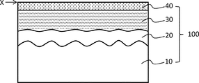
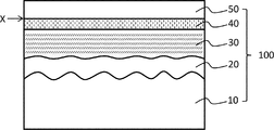
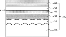
- FIGS. 1 to 3 are schematic cross-sectional views showing an embodiment of the barrier paper 100 of the present invention.
- the barrier paper 100 of FIGS. 1 to 3 has a paper base material layer 10, an adhesive layer 30, and an inorganic vapor deposition layer 40 in this order, and the adhesive layer 30 and the inorganic vapor deposition layer 40 are in contact with each other.
- the barrier paper 100 of FIGS. 1 to 3 has a sealing layer 20 between the paper base material layer 10 and the adhesive layer 30.
- the barrier paper 100 of FIG. 2 has a release layer 50 on the opposite side of the inorganic vapor deposition layer 40 from the adhesive layer 30.
- the barrier paper 100 of FIGS. 1 to 4 "the surface of the inorganic vapor deposition layer 40 opposite to the paper substrate layer 10" indicates the surface "X" in the drawing. That is, in the barrier paper 100 of FIGS. 1 to 4, Ra1, ⁇ Ra1 and Rku1 mean Ra1, ⁇ Ra1 and Rku1 of the X surface.
- the following (1) to (8) show an example of the laminated structure of the barrier paper of the present embodiment.
- the adhesive layer and the inorganic vapor deposition layer are in contact with each other and laminated.
- (1) A laminated structure having a paper base material layer, an adhesive layer, and an inorganic thin-film deposition layer in this order.
- (2) A laminated structure having a paper base material layer, an adhesive layer, an inorganic vapor deposition layer, and a release layer in this order.
- a laminated structure having a paper base material layer, an adhesive layer, and an inorganic vapor deposition layer in this order, and further having a heat seal layer or a sealant layer on the side opposite to the adhesive layer of the inorganic vapor deposition layer.
- a laminated structure having a paper base material layer, an adhesive layer, an inorganic vapor deposition layer, and a release layer in this order, and further having a heat seal layer or a sealant layer on the opposite side of the release layer from the inorganic vapor deposition layer.
- a laminated structure having a paper base material layer, an adhesive layer, an inorganic vapor deposition layer, and a protective layer in this order, and further having a heat seal layer or a sealant layer on the opposite side of the protective layer from the inorganic vapor deposition layer.
- a laminated structure having a paper base material layer, an adhesive layer, an inorganic vapor deposition layer, a protective layer, and a release layer in this order, and further having a heat seal layer or a sealant layer on the opposite side of the release layer from the inorganic vapor deposition layer. ..
- the paper base material layer, the adhesive layer, and the inorganic vapor-deposited layer are provided in this order, and heat is further applied to the side of the paper base material layer opposite to the adhesive layer and the side of the inorganic vapor-deposited layer opposite to the adhesive layer.
- the barrier paper of the present embodiment is not limited to the laminated structure of FIGS. 1 to 3 and the laminated structure of (1) to (8) above.
- the barrier paper of the present embodiment may have other layers such as a printing layer, a functional layer, a reinforcing layer, and a second adhesive layer as long as the effects of the present invention are not impaired.
- the other layers are arranged "between the paper base layer and the adhesive layer", "the side opposite to the adhesive layer of the paper base layer", and “the side opposite to the adhesive layer of the inorganic vapor deposition layer". ".
- the orientation of the barrier paper when using the barrier paper of this embodiment is not particularly limited.
- the orientation of the barrier paper is not limited, but it is preferable to use the barrier paper so that the inorganic vapor deposition layer side is the inner layer side with reference to the adhesive layer.
- the inside of the packaging material means the content side.
- ⁇ Paper base layer> As the paper base material constituting the paper base material layer, a general-purpose paper base material can be used. Examples of the paper base material include strong size bleached or unbleached paper base material, pure white roll paper, kraft paper, paperboard, coated paper, cast coated paper, milk base paper, processed base paper, high-quality paper, and fine paper. Examples thereof include coating printing paper, coating printing paper, resin coated paper, peeling base paper, and double-sided coating peeling base paper.
- the paper base material layer may be composed of one layer, or may be composed of multiple layers including two or more same or different paper base materials.
- the two or more paper substrates can be laminated by a general-purpose laminating means such as an adhesive.
- the basis weight and thickness of the paper substrate layer are not particularly limited.
- the basis weight of the paper substrate layer is preferably 30 g / m 2 or more and 600 g / m 2 or less, and more preferably 50 g / m 2 or more and 450 g / m 2 or less.
- the thickness of the paper base material layer is preferably 5 ⁇ m or more and 200 ⁇ m or less, more preferably 30 ⁇ m or more and 100 ⁇ m or less, and further preferably 40 ⁇ m or more and 80 ⁇ m or less.
- the raw material pulp for the paper substrate layer is preferably a mixture of softwood pulp (N material) and hardwood pulp (L material).
- the mixing ratio of the hardwood pulp (L material) is preferably 50% by mass or more and 90% by mass or less.
- the paper base material is preferably neutral paper, and more preferably neutral paper sized using an alkyl ketene dimer as a sizing agent.
- the paper substrate layer may contain additives such as lubricants, cross-linking agents, antioxidants, ultraviolet absorbers, light stabilizers, fillers, reinforcing agents, antistatic agents, pigments, etc., if necessary. ..
- additives such as lubricants, cross-linking agents, antioxidants, ultraviolet absorbers, light stabilizers, fillers, reinforcing agents, antistatic agents, pigments, etc., if necessary. ..
- physical surface treatment such as corona discharge treatment, ozone treatment, plasma treatment, glow discharge treatment, sandblast treatment, and chemistry. It is also possible to perform a chemical surface treatment such as an oxidation treatment using a chemical in advance.
- the ratio of the thickness of the paper substrate layer to the total thickness of the barrier paper is preferably 60% or more and less than 100%, more preferably 63% or more and 90% or less, and more preferably 65% or more and 80% or less.
- the ratio is preferably 60% or more and less than 100%, more preferably 63% or more and 90% or less, and more preferably 65% or more and 80% or less.
- the barrier paper of the present embodiment has an adhesive layer between the paper base material layer and the inorganic vapor deposition layer. Further, the adhesive layer needs to be laminated in contact with the inorganic thin-film deposition layer. When the adhesive layer and the inorganic vapor-deposited layer are in contact with each other and laminated, when a crack occurs on the adhesive layer side of the inorganic vapor-deposited layer, the adhesive layer repairs the crack and maintains the barrier property of the barrier paper. It can be done easily. Further, by having an adhesive layer between the paper base material layer and the inorganic vapor deposition layer, it is possible to easily make the surface shapes of Ra1, ⁇ Ra1, Rku1 and the like within the range described later.
- the adhesive layer is provided on substantially the entire surface of one side of the paper base material layer. “Approximately the entire surface” means 95% or more of the area on one side of the paper substrate layer, preferably 97% or more, more preferably 99% or more, and most preferably 100%.
- the adhesives constituting the adhesive layer include moisture-curable adhesives, anaerobic curable adhesives, dry-curable adhesives, UV-curable adhesives, heat-sensitive adhesives (for example, hot melt adhesives), and pressure-sensitive adhesives.
- Adhesives sin-called adhesives
- the above-mentioned adhesive may be a general-purpose adhesive or a specific adhesive.
- General-purpose adhesives include two-component curable urethane adhesives, polyester polyurethane adhesives, polyether polyurethane adhesives, acrylic adhesives, polyester adhesives, polyamide adhesives, and polyvinyl acetate adhesives. , Epoxy adhesives, rubber adhesives and the like.
- Examples of general-purpose adhesives include resins such as polyolefin resins, acid-modified polyolefin resins, polyvinyl acetate resins, poly (meth) acrylic resins, and polyvinyl chloride resins. These adhesives can be used alone or in combination of two or more.
- the specific adhesive is preferably an adhesive that protects the inorganic vapor deposition layer.
- the adhesive that protects the inorganic thin-film deposition layer is an adhesive that makes it easier to maintain the gas barrier property of the barrier paper by protecting the inorganic thin-film deposition layer that exhibits gas barrier properties. For example, when a bending load is applied to the barrier paper, the crack generation of the inorganic thin-film deposition layer is suppressed, and even when minute cracks start to occur in the inorganic thin-film deposition layer after the bending load, the action of suppressing the deterioration of the gas barrier property is suppressed. It is an adhesive that can be exerted. More detailed embodiments of the adhesive that protects the inorganic vapor deposition layer will be described later.
- the glass transition temperature of the adhesive layer is preferably ⁇ 30 ° C. or higher and 80 ° C. or lower, more preferably 0 ° C. or higher and 70 ° C. or lower, and further preferably 25 ° C. or higher and 70 ° C. or lower.
- the residual solvent in the adhesive layer is small.
- the residual solvent in the adhesive layer is preferably 6 mg / m 2 or less.
- the amount of residual solvent is most preferably 0 mg / m 2 , but practically it is preferably 6 mg / m 2 or less.
- the barrier paper does not contain a solvent-containing layer other than the adhesive layer, it can be detected as the solvent content of the adhesive layer by measuring the solvent content of the entire barrier paper.
- the thickness of the adhesive layer is preferably 1 ⁇ m or more and 20 ⁇ m or less, and more preferably 2 ⁇ m or more and 10 ⁇ m or less.
- the thickness of the adhesive layer is preferably 1 ⁇ m or more and 20 ⁇ m or less, and more preferably 2 ⁇ m or more and 10 ⁇ m or less.
- the thickness of the adhesive layer is preferably 1.5 ⁇ m or more and 20 ⁇ m or less.
- the thickness is 1.5 ⁇ m or more, the inorganic vapor-deposited layer can be easily protected, and when the thickness is 20 ⁇ m or less, the rigidity of the adhesive layer itself becomes too strong and the protective effect of the inorganic-deposited layer is lowered. Can be suppressed.
- the thickness of the adhesive layer can be calculated by, for example, the following methods (x1) to (x4).
- the thickness of the layers other than the adhesive layer can also be calculated by the same method as (x1) to (x4) below (however, in the following (x2) to (x4), the "adhesive layer” is the layer for which the thickness is calculated (x4). For example, it shall be read as "paper substrate layer, sealing layer, etc.)".
- Sample 1 is prepared by cutting the barrier paper in the direction perpendicular to the paper surface.
- (X2) A cross-sectional photograph 1 of an arbitrary portion in the width direction of the sample 1 is taken. Based on the cross-sectional photograph 1, the thickness of the adhesive layer is measured at 15 points at 1 ⁇ m intervals.
- the standard deviation of the thickness of the adhesive layer is preferably 0.80 ⁇ m or less, more preferably 0.60 ⁇ m or less, and even more preferably 0.55 ⁇ m or less.
- the barrier property can be improved more easily.
- the adhesive layer is in contact with the inorganic vapor deposition layer. Therefore, when the volume of the adhesive layer changes with time and stress is generated, the stress is directly transmitted to the adhesive layer.
- the thickness of the adhesive layer varies widely, the stress varies depending on the location, so that local defects may occur in the inorganic vapor-deposited layer.
- the barrier paper of the present embodiment has a paper base material layer having high moisture permeability, and the volume of the adhesive layer is likely to change due to moisture.
- the structure in which the standard deviation of the thickness of the adhesive layer is 0.80 ⁇ m or less is considered to be an advantageous structure for improving the barrier property.
- the standard deviation of the thickness of the adhesive layer is set to a predetermined value or more, the adhesion between the adhesive layer and the paper base material layer or the adhesive layer and the sealing layer can be improved by the anchoring action. Further, the adhesiveness of the entire barrier paper can be easily improved. Therefore, the standard deviation of the thickness of the adhesive layer is preferably 0.20 ⁇ m or more, more preferably 0.30 ⁇ m or more, and further preferably 0.35 ⁇ m or more.
- standard deviation means “standard deviation 1 ⁇ ” unless otherwise specified.
- the lower limit of the standard deviation of the thickness of the adhesive layer is not particularly limited, but is preferably 0.10 ⁇ m or more, and more preferably 0.20 ⁇ m or more.
- the standard deviation of the thickness of the adhesive layer means the standard deviation (standard deviation 1 ⁇ ) calculated from the thicknesses of the 75 points (x1) to (x4) above.
- the coefficient of variation of the thickness of the adhesive layer is preferably 0.17 or less, and more preferably 0.15 or less. By setting the coefficient of variation of the adhesive layer within the above range, the effect of the standard deviation of the adhesive layer can be more easily exhibited.
- the coefficient of variation of the thickness of the adhesive layer is not particularly limited, but is preferably 0.02 or more, and more preferably 0.05 or more.
- the coefficient of variation is a dimensionless value obtained by dividing the standard deviation by the average value.
- the adhesive layer contains additives such as antioxidants, UV absorbers, light stabilizers, antistatic agents, antiblocking agents, flame retardants, cross-linking agents, and colorants as long as the effects of the present invention are not impaired. Can include.
- a urethane-based resin composition is preferable as the adhesive that protects the inorganic thin-film deposition layer.
- the urethane-based resin composition preferably contains a specific polyol having two or more hydroxyl groups in one molecule and a specific isocyanate compound having two or more isocyanate groups in one molecule.
- the adhesive that protects the inorganic vapor deposition layer may further contain a phosphoric acid compound. Further, the adhesive that protects the inorganic vapor deposition layer may contain an inorganic compound.
- polyol having two or more hydroxyl groups in one molecule has two or more hydroxyl groups in one molecule, and the main skeleton is a polyester structure part, a polyester polyurethane structure part, a polyether structure part, an isocyanul ring structure part, and a poly.
- the polyol preferably has a polyester structure and / or a polyester polyurethane structure as the main skeleton, and more preferably has a polyester structure and / or a polyester polyurethane structure and an isocyanul ring structure.
- the hydroxyl group is preferably an alcoholic hydroxyl group, but may contain a phenolic hydroxyl group.
- the polyester structure can be obtained, for example, by polycondensing a polyvalent carboxylic acid and a polyhydric alcohol by a known and commonly used method, but the synthesis method is not limited to this.
- the polyester structural portion contains a polyester structural portion formed of an o-aromatic dicarboxylic acid and an aliphatic diol.
- the polyvalent carboxylic acid-derived structural portion in the polyester structural portion or the polyester polyurethane structural portion preferably contains 70% by mass or more and 100% by mass or less of the o-aromatic dicarboxylic acid-derived structural portion.
- the o-aromatic dicarboxylic acid refers to an o-aromatic dicarboxylic acid and a derivative thereof, and examples of the derivative include anhydrides and esters.
- the polyunsaturated carboxylic acids refer to polyunsaturated carboxylic acids and derivatives such as anhydrides and esters thereof, and examples thereof include aliphatic polyunsaturated carboxylic acids and aromatic polyunsaturated carboxylic acids.
- examples of the aliphatic polyvalent carboxylic acid include succinic acid, adipic acid, azelaic acid, sebacic acid, dodecanedicarboxylic acid, 1,4-cyclohexanedicarboxylic acid and the like.
- aromatic polyvalent carboxylic acids examples include o-phthalic acid, terephthalic acid, isophthalic acid, pyromellitic acid, trimellitic acid, 1,2-naphthalenedicarboxylic acid, 1,8-naphthalenedicarboxylic acid, and 2,3-naphthalenedicarboxylic acid.
- o-aromatic dicarboxylic acids examples include o-phthalic acid, 1,2-naphthalenedicarboxylic acid, 1,8-naphthalenedicarboxylic acid, 2,3-naphthalenedicarboxylic acid, 2,3-anthracene dicarboxylic acid, and 2,3-.
- examples thereof include anthracene dicarboxylic acid, an anhydride of dicarboxylic acid, and an ester of dicarboxylic acid.
- the above-mentioned multivalent carboxylic acids may be used alone or in combination of two or more.
- polyhydric alcohol examples include an aliphatic polyhydric alcohol and an aromatic polyhydric phenol.
- aliphatic polyhydric alcohol include ethylene glycol, propylene glycol, butylene glycol, neopentyl glycol, cyclohexanedimethanol, 1,5-pentanediol, 3-methyl-1,5-pentanediol, and 1,6-hexanediol.
- Diols such as methylpentanediol, dimethylbutanediol, butylethylpropanediol, diethylene glycol, triethylene glycol, tetraethylene glycol, dipropylene glycol, tripropylene glycol; triols such as glycerol, 1,2,4-butanetriol; Tetraols such as erythritol, pentaerythol, dipentaerythritol; and the like can be mentioned.
- aromatic polyhydric phenol examples include hydroquinone, resorcinol, catechol, naphthalenediol, biphenol, bisphenol A, hisphenol F and tetramethylbiphenol, and further, these ethylene oxide extensions and hydrogenated fats thereof. Examples include the ring tribe.
- the above-mentioned polyhydric alcohols may be used alone or in combination of two or more. When a structural part derived from triols is contained as a polyhydric alcohol in an adhesive that protects the inorganic thin-film deposition layer in an amount of 5% by mass or more, the adhesive is polyfunctionalized and the adhesive strength and strength are improved. Can be done.
- triol glycerol when used as the polyhydric alcohol, the polyol having a polyester structure in the main skeleton is represented by the following formulas (1) and (2).
- R 1 , R 2 , and R 3 each independently represent a hydrogen atom or a group represented by the general formula (2), and at least one represents a group represented by the general formula (2). Represent.
- n represents a number from 1 to 5 and X is a substituted and / or unsubstituted 1,2-phenylene group, 1,2-naphthylene group, 2,3.
- X is a substituted and / or unsubstituted 1,2-phenylene group, 1,2-naphthylene group, 2,3.
- Y represents an alkylene group having 2 to 6 carbon atoms.
- the isocyanate compound having two or more isocyanate groups in one molecule may be either aromatic or aliphatic as long as it has two or more isocyanate groups in the molecule, and may be either a low molecular weight compound or a high molecular weight compound.
- a known compound such as a diisocyanate compound having two isocyanate groups or a polyisocyanate compound having three or more isocyanate groups can be used.
- a blocked isocyanate compound obtained by an addition reaction using an isocyanate blocking agent by a general-purpose method can also be used.
- the isocyanate compound preferably contains an aromatic ring structure and / or a polyurethane structure containing an aromatic ring in the main skeleton.
- a polyisocyanate compound is preferable, and from the viewpoint of gas barrier property, a compound having an aromatic ring is preferable.
- an isocyanate compound containing a metaxylene skeleton is expected to improve gas barrier properties not only by hydrogen bonding of urethane groups but also by ⁇ - ⁇ stacking between aromatic rings, which is preferable.
- isocyanate compound having two or more isocyanate groups in one molecule include tetramethylene diisocyanate, hexamethylene diisocyanate, toluene diisocyanate, diphenylmethane diisocyanate, hydride diphenylmethane diisocyanate, metaxylylene diisocyanate, hydride xylylene diisocyanate and isophorone.
- Diisocyanates; trimerics of the above-mentioned isocyanate compounds; adducts, burettes, allophanates, etc. obtained by reacting the above-mentioned excess amounts of the isocyanate compounds with the following (a) to (c) and the like.
- (C) High molecular weight active hydrogen compounds such as polyester resins, polyether polyols and polyamides.
- isocyanate compound metaxylene diisocyanate or a reaction product of metaxylene diisocyanate and an alcohol having two or more hydroxyl groups is preferable.
- phosphoric acid compound phosphoric acids and / or phosphoric acid organic esters can be used, and they may be monomers or polymers.
- the phosphoric acid compound preferably has a hydroxyl group connected to a phosphorus atom.
- the phosphoric acid compound can enhance the adhesion of the adhesive that protects the inorganic vapor deposition layer.
- Phosphoric acids refer to phosphoric acids and multimers of phosphoric acids such as pyrophosphoric acid or polyphosphoric acid.
- the organic group of the phosphoric acid organic ester is preferably one or more selected from the group consisting of an alkyl group, a polyalkylene ether group, a (meth) acryloyl group, and a substituted or unsubstituted phenyl group.
- the content of the phosphoric acid compound in the adhesive that protects the inorganic thin-film deposition layer is preferably 0.005% by mass or more and 10% by mass or less, and more preferably 0.01% by mass or more and 1% by mass or less. If it is less than the above range, it may be difficult to obtain the effect of containing the phosphoric acid compound, and if it is more than the above range, the contained effect is not improved so much, and the content of other components is reduced, which has an adverse effect. It may be easier.
- Examples of the phosphoric acid compound include a compound represented by the following formula (3) or (4).
- Specific examples of the phosphoric acid compound include phosphoric acid, pyrophosphate, triphosphate, methyl acid phosphate, ethyl acid phosphate, butyl acid phosphate, dibutyl phosphate, 2-ethylhexyl acid phosphate, bis (2-ethylhexyl) phosphate, and isododecyl acid. Examples thereof include phosphate, butoxyethyl acid phosphate, oleyl acid phosphate, tetracosyl acid phosphate, 2-hydroxyethyl methacrylate acid phosphate, polyoxyethylene alkyl ether phosphoric acid and the like.
- R 1, R 2, R 3 represents a hydrogen atom, an alkyl group having 1 to 30 carbon atoms, (meth) acryloyl group, a substituted or unsubstituted phenyl group, ( Meta) One or more selected from the group consisting of alkyl groups having 1 to 4 carbon atoms having an acryloyloxy group, at least one is a hydrogen atom, and n represents a number of 1 to 4).
- R4 and R5 are hydrogen atoms, alkyl groups having 1 to 30 carbon atoms, (meth) acryloyl groups, substituted or unsubstituted phenyl groups, and (meth) acryloyloxy groups.
- the adhesive that protects the inorganic vapor deposition layer may contain an inorganic compound.
- the oxygen barrier property can be improved by containing an inorganic compound.
- the content of the inorganic compound in the adhesive that protects the inorganic vapor deposition layer is preferably 5% by mass or more and 50% by mass or less.
- the shape of the inorganic compound is not particularly limited, but a plate-like shape is preferable.
- the aspect ratio of the inorganic compound is preferably 3 or more, more preferably 10 or more, and even more preferably 40 or more.
- the aspect ratio of the inorganic compound is preferably 500 or less.
- the inorganic compound is preferably nonionic and uncharged, with low swelling property due to water, from the viewpoint of suppressing an increase in the viscosity of the adhesive and suppressing an increase in the thixotropy of the adhesive.
- the inorganic compound when the inorganic compound has a plate-like shape, it is preferable that the inorganic compound exhibits the above-mentioned properties.
- Plate-like inorganic compounds include, for example, hydrous silicates such as phyrosilicate minerals, kaolinite, kaolinite, enderite, deckite, nacrite and the like, kaolinite such as antigolite and chrysotile-serpentine clay minerals, pyrophylli. Pyrophyllites such as light, talc, and kerolai-talc, montmorillonite, byderite, nontronite, saponite, hectrite, soconite, smectite clay minerals such as stibunkite, vermiculite clay minerals such as vermiculite, white mica, and gold mica.
- hydrous silicates such as phyrosilicate minerals, kaolinite, kaolinite, enderite, deckite, nacrite and the like
- kaolinite such as antigolite and chrysotile-serpentine clay minerals
- pyrophylli Pyrophyllites such as light, tal
- the above-mentioned plate-like inorganic compound may be a natural clay mineral or a synthetic clay mineral, and may be used alone or in combination of two or more.
- kaolinite-serpentine clay minerals, pyrophyllite-talc, mica or mica clay minerals, green mudstones, hydrotalcites, and barium plate sulfates are non-swellable to water.
- kaolinite-serica clay minerals and pyrophyllite-talc are more preferred because they are nonionic and do not have interlayer electrification.
- the average particle size of the inorganic compound is not particularly limited, but is preferably 0.1 ⁇ m or more and 100 ⁇ m or less, and more preferably 1 ⁇ m or more and 20 ⁇ m or less.
- the average particle size means the mass average value d50 in the particle size distribution measurement by the laser light diffraction method.
- adhesives that protect the inorganic vapor-deposited layer include solvent-based barrier adhesive passrim (main agent VM001 / curing agent 108CP) and solvent-free barrier adhesive passrim (main agent NSRD011) manufactured by DIC Corporation. / Hardener NSRD006) and the like are known.
- a coating liquid containing a component constituting the adhesive layer is applied on a paper base material layer, an inorganic vapor deposition layer (on an inorganic vapor deposition layer of an inorganic vapor deposition layer donor), or a separator, and dried. , Can be formed by curing if necessary.
- the inorganic vapor deposition layer is located on the opposite side of the adhesive layer from the paper base material layer. Further, the inorganic vapor deposition layer is in contact with the adhesive layer. In other words, there is no other layer between the inorganic vapor deposition layer and the adhesive layer.
- the inorganic vapor deposition layer is provided on substantially the entire surface of the adhesive layer on the surface opposite to the paper base material layer. “Approximately the entire surface” means 95% or more of the area of the adhesive layer opposite to the paper base material layer, preferably 97% or more, more preferably 99% or more, and most preferably 100%.
- the barrier paper of the present embodiment has a ⁇ Ra1 of 0.030 ⁇ m or less when the arithmetic mean roughness of the surface of the inorganic vapor deposition layer opposite to the paper substrate layer is defined as Ra1 and the standard deviation of the Ra1 is defined as ⁇ Ra1. It is preferable to have.
- the arithmetic mean roughness means the arithmetic mean roughness Ra defined in JIS B0601: 2001.
- the cutoff ⁇ s and the cutoff ⁇ c when calculating the arithmetic mean roughness are both set to “0”.
- the surface of the inorganic vapor deposition layer opposite to the paper base material layer means the surface X in FIGS. 1 to 4.
- 1 to 3 are schematic cross-sectional views showing one embodiment of the barrier paper of the present invention
- FIG. 4 is a schematic cross-sectional view showing one embodiment of the conventional barrier paper.
- the surface of the inorganic vapor deposition layer opposite to the paper base material layer may be referred to as "surface X".
- ⁇ Ra1 By setting ⁇ Ra1 to 0.030 ⁇ m or less, the barrier property can be easily improved.
- the reason for this is considered as follows. First, the fact that ⁇ Ra1 exceeds 0.030 ⁇ m means that the value of the arithmetic mean roughness of the surface of the inorganic vapor-deposited layer opposite to the paper substrate layer varies greatly from place to place. When the value of the arithmetic mean roughness of the inorganic vapor-deposited layer varies greatly from place to place, the physical characteristics of the inorganic-deposited layer also tend to differ from place to place.
- ⁇ Ra1 exceeds 0.030 ⁇ m, it is considered that a portion where the barrier property becomes small is likely to occur in a local region in the plane of the inorganic thin-film deposition layer. As a result of water vapor or gas permeating locally from the region where the barrier property is weak, it is considered that it is difficult for the barrier paper having ⁇ Ra1 of more than 0.030 ⁇ m to improve the barrier property. On the other hand, when ⁇ Ra1 is 0.030 ⁇ m or less, it is difficult to generate a portion where the barrier property becomes small in the in-plane local region of the inorganic thin-film deposition layer. Therefore, it is considered that a barrier paper having a ⁇ Ra1 of 0.030 ⁇ m or less tends to have good barrier properties.
- ⁇ Ra1 is preferably 0.025 ⁇ m or less, more preferably 0.022 ⁇ m or less, and further preferably 0.020 ⁇ m or less.
- the lower limit of ⁇ Ra1 is not particularly limited, but is preferably 0.001 ⁇ m or more, more preferably 0.002 ⁇ m or more, and further preferably 0.005 ⁇ m or more.
- Ra1 means the average value of the arithmetic mean roughness Ra of 72 places. Further, in the present specification, ⁇ Ra1 means the standard deviation (standard deviation 1 ⁇ ) of the arithmetic mean roughness Ra at 72 points.
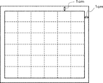
- the measurement sample is preferably sampled excluding the bent portion (for example, when sampling from a container formed of using barrier paper, it is preferable to sample excluding the bent portion). When the measurement sample is a quadrangle, as shown in FIG.
- the area 1 cm from the outer edge of the quadrangle is set as a margin, and the area inside the margin is divided into 6 equal parts in the vertical and horizontal directions for measurement within 36 areas. .. Then, the surface shapes in the vertical direction and the horizontal direction are measured within the 36 regions, and 72 measured values are obtained. Then, Ra1 is calculated from the average of the measured values of 72, and ⁇ Ra1 is calculated from the standard deviation (standard deviation 1 ⁇ ) of the measured values of 72.
- the measurement sample has a shape other than a quadrangle such as a circle, an ellipse, a triangle, or a pentagon, it is preferable to draw a quadrangle inscribed in these shapes and obtain 72 measurement values for the quadrangle by the above method.
- the surface shape of the surface of the inorganic vapor deposition layer opposite to the paper base material layer can be measured by, for example, a non-contact type surface shape measuring instrument.
- the non-contact type surface shape measuring instrument include a confocal type and a white interference type.
- the surface shape is measured by the confocal method among the non-contact type surface shape measuring instruments.
- the focus of light of the confocal surface shape measuring instrument The surface shape of the surface X can be measured by aligning the surface X with the surface X.
- Examples of the confocal surface shape measuring instrument include the product name "VK-X150" manufactured by KEYENCE CORPORATION.
- the confocal surface shape measuring instrument can measure the surface shape of any area. Then, if the horizontal direction of an arbitrary position is selected within the measured arbitrary area, Ra1 in the horizontal direction of the position can be calculated, and if the vertical direction of the arbitrary position is selected, the vertical direction of the position is selected. The arithmetic mean roughness of the direction can be calculated. In the case of the above-mentioned confocal surface shape measuring instrument (keyence brand name "VK-X150”), the horizontal direction of an arbitrary position or the vertical direction of an arbitrary position on the screen of the surface shape displayed two-dimensionally. By selecting, the arithmetic mean roughness in the selected direction can be calculated.
- the size of the measurement area in each measurement is not particularly limited, but the lower limit is preferably 100 ⁇ m in length ⁇ 100 ⁇ m in width or more, and the upper limit is preferably 500 ⁇ m in length ⁇ 500 ⁇ m in width or less.
- Ra1 and ⁇ Ra1 can be calculated, for example, by the following procedures (A1) to (A4).
- Rku1 to be described later can also be calculated, for example, by the same procedure as (A1) to (A4) below (however, the "arithmetic mean roughness" of (A3) and (A4) below can be calculated as "curtosis of roughness curve”. , And replace “Ra1" in (A4) below with "Rku1").
- A1 The measurement sample is divided into 36 regions as described above.
- A2 Using a confocal surface shape measuring instrument, the surface shape of an arbitrary area near the center in the 36 regions is measured.
- ⁇ Ra1 In order to make it easier for ⁇ Ra1 to be 0.030 ⁇ m or less, it is preferable to suppress the roughness of the paper substrate layer from being reflected in the inorganic vapor deposition layer. Therefore, it is preferable to arrange an adhesive layer between the paper base material layer and the inorganic vapor deposition layer, and it is more preferable to arrange a sealing layer and an adhesive layer. Further, in order to easily reduce ⁇ Ra1 to 0.030 ⁇ m or less, it is preferable to use a support having a substantially smooth surface shape as a support having an inorganic vapor deposition layer formed by a transfer method and having releasability.
- ⁇ Ra1 Since the inorganic vapor deposition layer formed as described above reflects the substantially smooth surface shape of the support having releasability, ⁇ Ra1 can be easily reduced.
- the above-mentioned means for facilitating the reduction of ⁇ Ra1 is also useful as a means for facilitating Ra1 in the range described later and a means for facilitating Rku in the range described later.
- the barrier paper of the present embodiment preferably has Ra1 of 0.100 ⁇ m or less.
- Ra1 is more preferably 0.080 ⁇ m or less, more preferably 0.070 ⁇ m or less, and even more preferably 0.065 ⁇ m or less.
- the lower limit of Ra1 is not particularly limited, but is preferably 0.001 ⁇ m or more, more preferably 0.002 ⁇ m or more, and further preferably 0.005 ⁇ m or more.
- the barrier paper of the present embodiment preferably has ⁇ Ra1 / Ra1 of 0.40 or less, and more preferably 0.30 or less.
- ⁇ Ra1 / Ra1 is a dimensionless value obtained by dividing the standard deviation by the average value, and is a so-called coefficient of variation.
- the barrier paper of the present embodiment preferably has Rku1 of more than 3.0 when the roughness curve of the surface opposite to the paper base material layer of the inorganic vapor deposition layer is defined as Rku1.
- Rku1 When the height distribution of the surface shape is divided into low, average, and high points, an Rku1 exceeding 3.0 means that there are many average points and few low and high points. To do. Therefore, when Rku1 exceeds 3.0, it is possible to prevent the barrier property from becoming small in a local region in the plane of the inorganic thin-film deposition layer, and it is possible to easily improve the barrier property.
- Rku1 is more preferably 5.0 or more, more preferably 7.5 or more, and even more preferably 10.0 or more.
- the upper limit of Rku1 is not particularly limited, but is preferably 30.0 or less, more preferably 25.0 or less, and even more preferably 20.0 or less.
- Rku1 means the average value of Kurtosis of the roughness curve at 72 points.
- the roughness curve Kurtosis means the roughness curve Kurtosis Rku defined in JIS B0601: 2001.
- the cutoff ⁇ s and the cutoff ⁇ c when calculating the arithmetic mean roughness are both set to “0”.
- Examples of the method for forming the inorganic vapor deposition layer include physical vapor deposition (PVD) such as vacuum vapor deposition, sputtering, and ion plating, plasma chemical vapor deposition, thermochemical vapor deposition, and photochemical vapor deposition.
- PVD physical vapor deposition
- CVD chemical vapor deposition
- the inorganic vapor deposition layer may be transparent or opaque. If the inorganic thin-film deposition layer is opaque, the barrier paper can be provided with a light-shielding property, and the quality of the contents can be easily maintained. When the inorganic thin-film deposition layer is transparent, it is preferable because it is easy to use in a microwave oven, it is easy to inspect it with a metal detector after filling the contents, and the color of the print layer is unlikely to sink.
- the inorganic compound constituting the inorganic vapor deposition layer include metals, metal oxides, metal nitrides, and metal carbides. As the inorganic compound constituting the inorganic vapor deposition layer, two or more kinds of inorganic compounds may be mixed.
- metal elements constituting the above-mentioned inorganic compound include aluminum (Al), silicon (Si), magnesium (Mg), calcium (Ca), potassium (K), tin (Sn), and sodium (Na). ), Boron (B), Titanium (Ti), Lead (Pb), Zirconium (Zr), Yttrium (Y), Zinc (Zn), Vanadium (V), Barium (Ba), Chromium (Cr) and the like. ..
- the inorganic compound examples include the metal, the oxide of the metal, the nitride of the metal, and the carbide of the metal, and further, a composite such as indium tin oxide (ITO) and a SiO x Cy film.
- ITO indium tin oxide
- SiO x Cy film a composite such as indium tin oxide (ITO) and a SiO x Cy film.
- Metal oxides are preferable because they tend to make the inorganic vapor-deposited layer transparent and are chemically stable. Further, metal oxides are preferable in that they are easy to use in a microwave oven, easy to inspect with a metal detector after filling the contents, and the color of the print layer is unlikely to become a sunken color.
- aluminum, aluminum oxide and silicon oxide are preferable, and aluminum oxide and silicon oxide are more preferable.
- Representation of the average composition of the inorganic compound for example, SiO x, AlO x, MO x, represented by MO x C y as such SiO x C y
- MO x represents a metal element
- x , Y values have different ranges depending on the metal element.
- the range of x values is 0 to 2 for silicon, 0 to 1.5 for aluminum, 0 to 1 for magnesium, 0 to 1 for calcium, and 0 to 0 for potassium.
- tin is 0 to 2
- sodium is 0 to 0.5
- boron is 0 to 1
- titanium is 0 to 2
- lead is 0 to 1
- zirconium is 0 to 2
- yttrium is It can take a value in the range of 0 to 1.5.
- the upper limit of the range of x is a value when completely oxidized.
- aluminum oxide preferably has a value in the range of 0.5 to 1.5
- silicon oxide preferably has a value in the range of 1.0 to 2.0.
- the inorganic vapor deposition layer may be composed of one layer, or may be composed of multiple layers having the same or different composition.
- the thickness of the inorganic thin-film deposition layer is preferably 30 ⁇ or more and 3000 ⁇ or less, more preferably 40 ⁇ or more and 2500 ⁇ or less, and further preferably 50 ⁇ or more and 2000 ⁇ or less.
- the thickness of the inorganic vapor deposition layer made of aluminum oxide is preferably 30 ⁇ or more and 1000 ⁇ or less, and more preferably 50 ⁇ or more and 500 ⁇ or less.
- the thickness of the inorganic vapor deposition layer made of silicon oxide is preferably 30 ⁇ or more and 3000 ⁇ or less, and more preferably 100 ⁇ or more and 300 ⁇ or less.
- the inorganic thin-film deposition layer can be formed by, for example, "a method of directly depositing an inorganic compound on an adhesive layer (direct vapor deposition method)" or "transfer method".
- a method of directly depositing an inorganic compound on an adhesive layer direct vapor deposition method
- transfer method an inorganic thin-film deposition layer donor having an inorganic thin-film deposition layer on a support having releasability and a paper base material layer are bonded together via an adhesive layer, and then inorganic vapor deposition is performed on the paper base material layer. This is a method of forming a layer by transfer.
- the transfer method is preferable in that the paper base material layer does not have a problem due to exposure to the vapor deposition atmosphere and the adhesion between the adhesive layer and the inorganic vapor deposition layer can be easily improved. .. Further, the transcription method is preferable in that Ra1, ⁇ Ra1 and Rku1 can be easily set in the above-mentioned range.
- the transfer method depends on the method of forming the adhesive layer, "1. A type in which an adhesive layer is formed on the inorganic vapor deposition layer of the inorganic vapor deposition layer donor", and "2. An adhesive layer is formed on the paper base material layer". "Type", "3.
- a type that forms an adhesive layer on both the inorganic vapor deposition layer of the inorganic vapor deposition layer donor and the paper substrate "4.
- a type that supplies an adhesive layer between them” can be mentioned.
- the types of "2" and "4" are preferable.
- the types "2" and "4" can exclude the above-mentioned possibility. Is.
- "2" is preferable because it is easy to improve the adhesion between the paper base material layer and the adhesive layer.
- the interlayer adhesion strength between the adhesive layer and the inorganic vapor deposition layer is preferably one of categories 0, 1 and 2 in the cross-cut test according to JIS K5600-5-6, and is classified into categories 0 and 1. It is more preferable to be either. If the classification is lower than the above range, classifications 3, 4 or 5, peeling occurs between the adhesive layer and the inorganic thin-film deposition layer, and the gas barrier property tends to be lowered.
- the outline of the evaluation of the interlayer adhesion strength is as follows.
- a plurality of right-angled lattice patterns are formed by cutting through the inorganic thin-film layer on the barrier paper with a cutter knife or the like.
- a cross-cutting jig capable of continuously and neatly forming a plurality of right-angled grid patterns.
- an adhesive tape having an adhesive layer on one side such as an adhesive cellophane tape, is attached so as to cover the entire lattice formed above.
- Tencilon the attached adhesive tape is peeled off from the end, the peeling condition of the inorganic thin-film deposition layer is visually observed, and the results are classified according to the following evaluation criteria.
- the size of one side of the lattice pattern is preferably 1 mm or more and 5 mm or less, more preferably 1.5 mm or more and 3 mm or less, and further preferably about 2 mm.
- the number of lattice patterns is preferably 15 or more and 50 or less, more preferably 20 or more and 30 or less, and further preferably about 25.
- the width and length of the adhesive tape are preferably a size that covers all of the formed lattice patterns and is easy to peel off.
- the adhesive tape is peeled off using Tencilon or the like at a constant speed of preferably 1 mm / min or more and 5 mm / min or less, more preferably 2 mm / min or more and 4 mm / min or less, and further preferably about 3 mm / min.
- Category 0 The edges of the cut are perfectly smooth and there is no peeling in any grid.
- Category 1 There is a small peeling of the coating film at the intersection of the cuts. However, the cross-cut portion is clearly not affected by more than 5%.
- Category 2 There is peeling along the edge of the cut of the coating and / or at the intersection. The cross-cut area is clearly affected between 5% and 15%.
- Category 3 The coating film is partially or wholly peeled off along the edges of the cut, and / or various parts of the eye are partially or wholly peeled off. The cross-cut area is affected by more than 15% and less than 35%.
- Category 4 The coating film is partially or wholly peeled off along the edges of the cut, and / or several eyes are partially or wholly peeled off. The area affected by the cross-cut part is clearly not more than 35%.
- Category 5 Any degree of peeling that cannot be classified even in Category 4.
- the barrier paper of the present embodiment preferably has a sealing layer between the paper base material layer and the adhesive layer.
- the sealing layer By having the sealing layer, the standard deviation and the coefficient of variation of the thickness of the adhesive layer can be easily set in the above-mentioned range. Further, by having a sealing layer in addition to the adhesive layer between the paper base material layer and the inorganic vapor deposition layer, it is possible to easily make the surface shape of ⁇ Ra1 or the like within the above-mentioned range.
- the sealing layer include a clay coat layer and a resin layer.
- the clay coat layer preferably contains clay and a binder.
- any clay generally called clay can be used without particular limitation.
- Specific examples of clay include kaolin, talc, bentonite, smectite, vermiculite, mica, chlorite, knot clay, gailome clay, halloysite, mica and the like. Since talc has a low hardness (Mohs hardness 1) and is excellent in heat resistance, it is possible to improve heat resistance and dimensional stability during embossing.
- the binder is usually a latex-based binder (for example, styrene-butadiene latex, acrylic-based latex, vinyl acetate-based latex), or a water-soluble binder (for example, starch (modified starch, oxidized starch, hydroxyethyl etherified starch, phosphate ester). Chemicalized starch), polyvinyl alcohol, casein, etc.).
- a latex-based binder for example, styrene-butadiene latex, acrylic-based latex, vinyl acetate-based latex
- a water-soluble binder for example, starch (modified starch, oxidized starch, hydroxyethyl etherified starch, phosphate ester). Chemicalized starch), polyvinyl alcohol, casein, etc.
- the clay coat layer preferably contains pigments such as calcium carbonate, titanium dioxide, amorphous silica, foamed barium sulfate, and satin white in order to improve the smoothness of the surface of the clay coat layer.
- pigments such as calcium carbonate, titanium dioxide, amorphous silica, foamed barium sulfate, and satin white.
- the clay coat layer may further contain additives such as a pigment dispersant, a defoaming agent, an effervescence inhibitor, a viscosity modifier, a lubricant, a water resistant agent, and a water retaining agent.
- the thickness of the clay coat layer is preferably 5 g / m 2 or more and 40 g / m 2 or less, and more preferably 10 g / m 2 or more and 40 g / m 2 or less.
- the thickness of the clay coat layer is preferably 3 ⁇ m or more and 40 ⁇ m or less, and more preferably 10 ⁇ m or more and 30 ⁇ m or less.
- the clay coat layer can be formed, for example, by applying a coating liquid containing components constituting the clay coat layer on a paper base material layer by a general-purpose coating method and drying it. Examples of the solvent for the clay coat layer coating liquid include water and alcohol.
- the resin constituting the resin layer examples include polyolefin-based resin, acrylic-based resin, urethane-based resin, and PVA (polyvinyl alcohol).
- the resin layer can be formed, for example, by coating on a paper base material layer.
- the thickness of the resin layer is preferably 10 ⁇ m or more because the effect of the sealing layer described above can be easily exerted.
- the thickness of the resin layer is preferably 60 ⁇ m or less because of its recyclability.
- the barrier paper of the present embodiment preferably has one or more layers selected from a release layer, a protective layer, a heat seal layer, and a sealant layer on the opposite side of the inorganic vapor deposition layer from the adhesive layer.
- the barrier paper may have a release layer on the opposite side of the inorganic vapor deposition layer from the adhesive layer.
- the release layer is a layer provided as needed to facilitate the release of the support having releasability from the inorganic vapor deposition layer donor.
- the release layer and the inorganic vapor deposition layer are transferred onto the paper substrate layer via the adhesive layer by using the inorganic vapor deposition layer donor on the support having releasability. Will be located on the opposite side of the inorganic vapor deposition layer from the adhesive layer.
- the release layer can function as a protective layer of the inorganic vapor deposition layer.
- the release layer can easily average and flatten the surface shape of the support having releasability. Therefore, by having the release layer, the surface shape of ⁇ Ra1 or the like can be easily set in the above-mentioned range.
- the release layer is provided on substantially the entire surface of the surface opposite to the adhesive layer of the inorganic vapor deposition layer. “Approximately the entire surface” means 95% or more of the area of the inorganic vapor-deposited layer opposite to the adhesive layer, preferably 97% or more, more preferably 99% or more, and most preferably 100%.
- the release layer is not particularly limited as long as it exhibits a well-balanced adhesive strength for achieving transfer of the inorganic vapor-filmed layer, but preferably contains a resin and / or wax.
- the resin include polyester-based resin, acrylic-based resin, silicone-based resin, polyvinyl butyral-based resin, acetal-based resin, and the like. Among these, polyester-based resins and acrylic-based resins are preferable.
- the wax include carbana wax, paraffin wax, polyethylene wax, polypropylene wax and the like. Among these, polyethylene wax is preferable.
- the release layer does not substantially contain particles such as pigments and matting agents in order to facilitate the surface shape of ⁇ Ra1 and the like within the above-mentioned range.
- substantially free means 0.1% by mass or less of the total solid content constituting the release layer, preferably 0.01% by mass or less, more preferably 0.001% by mass or less, and most preferably. Is 0% by mass.
- the coating amount of the release layer is preferably 0.2 g / m 2 or more and 5.0 g / m 2 or less.
- the thickness of the release layer is preferably 0.1 ⁇ m or more and 10 ⁇ m or less.
- the barrier paper may have a protective layer.
- the protective layer is preferably provided on the opposite side of the inorganic vapor deposition layer from the adhesive layer in order to protect the inorganic vapor deposition layer.
- the protective layer can easily average and flatten the surface shape of the support having releasability. Therefore, by having the protective layer, it is possible to easily make the surface shape of ⁇ Ra1 or the like within the above-mentioned range.
- the protective layer is provided on substantially the entire surface of the surface opposite to the adhesive layer of the inorganic vapor deposition layer. “Approximately the entire surface” means 95% or more of the area of the inorganic vapor-deposited layer opposite to the adhesive layer, preferably 97% or more, more preferably 99% or more, and most preferably 100%.
- the protective layer has, for example, "1. Applying and drying the protective layer coating liquid on the inorganic thin-film deposition layer", "2. Transferring the protective layer onto the inorganic thin-film deposition layer”, and "3. Releasability".
- an inorganic vapor deposition layer donor having a protective layer and an inorganic vapor deposition layer in this order on the support, and transferring the inorganic vapor deposition layer and the protective layer to the paper base material layer via the adhesive layer.
- "3" is preferable in order to improve workability and suppress defects in the inorganic thin-film deposition layer.
- the protective layer may be a resin component alone, an inorganic component alone, or a mixture of the resin component and the inorganic component.
- the protective layer preferably contains at least one selected from a water-soluble polymer and a metal alkoxide-based compound. Further, the protective layer more preferably contains at least one selected from the water-soluble polymer among the water-soluble polymer and the metal alkoxide-based compound, and one or more selected from the water-soluble polymer and the metal alkoxide-based compound. It is more preferable to include one or more selected from the compounds.
- the water-soluble polymer examples include polyvinyl alcohol, polyvinylpyrrolidone, and ethylene-vinyl alcohol copolymer.
- polyvinyl alcohol and ethylene-vinyl alcohol copolymer are preferable from the viewpoint of barrier properties, and polyvinyl alcohol is preferable. Is more preferable. That is, the protective layer preferably contains one or more selected from polyvinyl alcohol and an ethylene-vinyl alcohol copolymer, and more preferably contains polyvinyl alcohol.
- the content of the water-soluble polymer with respect to 100 parts by mass of the total amount of the metal alkoxide-based compound may be 5 parts by mass or more and 500 parts by mass or less. It is more preferably 7 parts by mass or more and 100 parts by mass or less, and further preferably 8 parts by mass or more and 50 parts by mass or less.
- the metal alkoxide compound examples include a metal alkoxide, a metal alkoxide hydrolyzate, and a metal alkoxide polymer.
- the metal alkoxide is a compound represented by the general formula of M (OR) n.
- M represents a metal such as Si, Ti, Al and Zr
- R represents an alkyl group such as a methyl group and an ethyl group.
- Specific examples of the metal alkoxide include tetramethoxysilane, tetraethoxysilane, isopropoxyaluminum and the like.
- the protective layer can be formed, for example, by applying a coating liquid containing a component constituting the protective layer on a support having releasability of the inorganic thin-film deposition layer donor and drying it.
- the coating liquid may contain additives such as a silane coupling agent, a curing agent and a dispersant.
- the protective layer does not substantially contain particles such as pigments and matting agents in order to facilitate the surface shape of ⁇ Ra1 and the like within the above-mentioned range.
- substantially free means 0.1% by mass or less of the total solid content constituting the protective layer, preferably 0.01% by mass or less, more preferably 0.001% by mass or less, and most preferably. Is 0% by mass.
- the lower limit of the thickness of the protective layer is preferably 70 nm or more, more preferably 85 nm or more, and further preferably 100 nm or more in order to protect the inorganic thin-film deposition layer and facilitate the improvement of the barrier property.
- the upper limit of the thickness of the protective layer is preferably 480 nm or less, more preferably 400 nm or less, and further preferably 300 nm or less.
- the barrier paper may have a heat seal layer.
- the heat seal layer is preferably provided on the side opposite to the adhesive layer of the inorganic vapor deposition layer.
- at least one of a release layer and a protective layer may be provided between the inorganic vapor deposition layer and the heat seal layer in order to protect the inorganic vapor deposition layer from the heat seal layer.
- the heat seal layer has a function as an adhesive layer when, for example, the barrier paper is formed into a container.
- the heat seal layer can be formed from, for example, a general-purpose thermoplastic resin.
- the thickness of the heat seal layer is usually about 15 ⁇ m or more and 100 ⁇ m or less.
- the heat seal layer is, for example, "1. Melting and extruding the heat seal layer onto the inorganic vapor deposition layer", “2. Applying and drying the heat seal layer coating liquid on the inorganic vapor deposition layer”, “3. Inorganic Transferring the heat seal layer onto the vapor deposition layer ”,“ 4. Prepare an inorganic vapor deposition layer donor having a heat seal layer and an inorganic vapor deposition layer in this order on a support having releasability, and use it as a paper substrate layer. On the other hand, it can be formed by "transferring the inorganic vapor deposition layer and the heat seal layer via the adhesive layer” and "5. dry laminating the heat seal layer on the inorganic vapor deposition layer".
- “1”, “2”, “3” and “5" are preferable from the viewpoint of reducing the vapor deposition cost of the inorganic vapor deposition layer. Further, in the case of “1”, “2”, “3” and “5", it is preferable to have at least one of a release layer and a protective layer between the inorganic vapor deposition layer and the heat seal layer. Further, when at least one of a release layer and a protective layer is provided between the inorganic vapor deposition layer and the heat seal layer, "1" is included in “1", “2”, “3” and "5".
- the barrier paper may have a sealant layer.
- the sealant layer is preferably provided on the opposite side of the inorganic vapor deposition layer from the adhesive layer.
- the sealant layer has a function of preventing the contents to be put in the container from coming into contact with other layers of the barrier paper and protecting the contents when the barrier paper is used as a container, for example.
- the thickness of the sealant layer is not particularly limited, and is appropriately set according to the use of the barrier paper and the type and properties of the contents.
- the thickness of the sealant layer is preferably 10 ⁇ m or more and 200 ⁇ m or less.
- the thickness of the sealant layer is more preferably 15 ⁇ m or more and 150 ⁇ m or less, and further preferably 20 ⁇ m or more and 100 ⁇ m or less.
- Materials constituting the sealant layer include propylene-based resins such as propylene homopolymer, ethylene-propylene block copolymer, and ethylene-propylene random copolymer, high-density polyethylene (HDPE), low-density polyethylene (LDPE), and linear low-density polyethylene. Chain low density polyethylene (L-LDPE) can be mentioned, and one or more of these resins can be used.
- propylene-based resins such as propylene homopolymer, ethylene-propylene block copolymer, and ethylene-propylene random copolymer, high-density polyethylene (HDPE), low-density polyethylene (LDPE), and linear low-density polyethylene.
- HDPE high-density polyethylene
- LDPE low-density polyethylene
- L-LDPE Chain low density polyethylene
- the sealant layer may be composed of a single layer or may be composed of two or more layers.
- the sealant layer preferably has a heat-sealing property.
- the sealant layer has a multi-layer structure, it is preferable that the side of the sealant layer opposite to the inorganic vapor deposition layer has a heat-sealing property.
- the sealant layer When the barrier paper is used as the lid of the container with a lid, the sealant layer preferably has an easy peel property.
- the easy peel property refers to a characteristic that the lid body can be easily peeled off from the container body when opening the container with a lid, for example.
- the sealant layer having easy peeling property uses two or more kinds of resins, and one resin (resin having good adhesion to the container body) and another resin (adhesion to the container body is not good), and the above It can be formed by mixing one resin and an incompatible resin).
- Such a resin cannot be unequivocally stated because it differs depending on the material of the container, but when the container body is made of polypropylene, polypropylene, which is one resin (resin having good adhesion to the container body), and others.
- a sealant layer from a resin that is a mixture of one or more selected from polyethylene, polypropylene, and polystyrene, which are the resins of the above (resin that does not have good adhesion to the container body and is incompatible with the above resin).
- Easy peeling property can be imparted to a polypropylene container.
- the sealant layer may be formed in a multi-layer structure, and easy peeling property may be imparted only to the side of the sealant layer to be joined to the container body.
- the sealant layer is, for example, "1. Melting and extruding the sealant layer onto the inorganic vapor deposition layer", “2. Applying and drying the sealant layer coating liquid on the inorganic vapor deposition layer", “3. On the inorganic vapor deposition layer”. Transfer the sealant layer to the surface ”,“ 4. Prepare an inorganic vapor deposition layer donor having a sealant layer and an inorganic vapor deposition layer in this order on a support having releasability, and apply an adhesive to the paper substrate layer. It can be formed by "transferring the inorganic vapor deposition layer and the sealant layer through the layer” and "5. dry laminating the sealant layer on the inorganic vapor deposition layer".
- “1”, “2”, “3” and “5" are preferable from the viewpoint of reducing the vapor deposition cost of the inorganic vapor deposition layer. Further, in the case of “1”, “2”, “3” and “5", it is preferable to have at least one of a release layer and a protective layer between the inorganic vapor deposition layer and the sealant layer.
- the barrier paper may have a print layer.
- the printing layer is preferably provided on the side opposite to the adhesive layer of the paper base material layer. Examples of the printing layer include a layer formed by printing characters (product name, product display, quality display, etc.), figures, photographs, symbols, patterns, patterns, etc., and a layer printed on one surface (so-called solid printing layer). And so on.
- the print layer may be a single layer or a multi-layer.
- the thickness of the print layer is usually 0.2 ⁇ m or more and 10.0 ⁇ m or less, preferably 0.5 ⁇ m or more and 8.0 ⁇ m or less, and more preferably 0.7 ⁇ m or more and 5.0 ⁇ m or less.
- Binder resins include acrylic resins, styrene resins, polyester resins, polyurethane resins, chlorinated polyolefin resins, vinyl chloride-vinyl acetate copolymer resins, polyvinyl butyral resins, alkyd resins, petroleum resins, and ketones. Examples thereof include resins, epoxy resins, melamine resins, fluorine resins, silicone resins, fibrous derivatives, rubber resins and the like. These may be used alone or in combination of two or more.
- the barrier paper may have a reinforcing layer.
- the reinforcing layer is preferably provided on the side opposite to the adhesive layer of the paper base material layer and / or on the side opposite to the adhesive layer of the inorganic thin-film deposition layer.
- the reinforcing layer is, for example, a barrier paper having one or more functions selected from mechanical strength, deformation resistance, drop impact resistance, pinhole resistance, heat resistance, sealing property, quality maintainability, workability, and hygiene. Is formed to grant.
- the reinforcing layer include a resin film, a resin coating film, and synthetic paper formed by extrusion or inflation.
- the resin contained in the reinforcing layer include low-density polyethylene, medium-density polyethylene, high-density polyethylene, linear low-density polyethylene, polypropylene, ethylene-propylene copolymer, and ethylene-vinyl acetate copolymer.
- ionomer resin ethylene-ethyl acrylate copolymer, ethylene-acrylic acid copolymer, ethylene-methacrylic acid copolymer, methylpentene polymer, polybutene resin, polyvinyl chloride resin, polyvinyl acetate resin, Polyvinylidene chloride resin, vinyl chloride-vinylidene chloride copolymer, poly (meth) acrylic resin, polyacrylic nitrile resin, polystyrene resin, acrylonitrile-styrene copolymer (AS resin), acrylonitrile-butadiene-styrene Copolymer (ABS-based resin), polyester-based resin, polyamide-based resin, polycarbonate-based resin, polyvinyl alcohol-based resin, saponified ethylene-vinyl acetate copolymer, fluorine-based resin, diene-based resin, polyacetal-based resin, polyurethane Examples include based resins, cellulose
- any of unstretched film, uniaxially stretched film, and biaxially stretched film can be used as the resin film constituting the reinforcing layer.
- the thickness of the reinforcing layer is not particularly limited, but is preferably 1 ⁇ m or more and 300 ⁇ m or less.
- the barrier paper may have a functional layer.
- the functional layer is preferably provided on the side opposite to the adhesive layer of the paper base material layer and / or on the side opposite to the adhesive layer of the inorganic thin-film deposition layer.
- a functional layer that imparts a barrier property to oxygen gas, water vapor, etc. a functional layer that absorbs less fragrance components contained in the contents and has excellent fragrance retention, a functional layer that imparts light-shielding property, and oxygen.
- a functional layer that absorbs examples include a functional layer that absorbs.
- the functional layer may contain one or more resins selected from a saponified ethylene-vinyl acetate copolymer, a polyamide resin, a polyacrylonitrile resin, and a polyester resin.
- the functional layer preferably contains particles made of a material having high light-shielding property such as titanium oxide, carbon black and aluminum scales, and a binder resin.
- the functional layer preferably contains particles made of a material having high oxygen absorption such as iron powder and a binder resin.
- Barrier paper temperature 40 ° C., at a relative humidity of 90%, a water vapor permeability measured according to JIS K7129 method, is preferably from 0.01g / m 2 / 24hr or 20g / m 2 / 24hr, 0.01g / m 2/24 hr or more 10g / m 2 / 24hr or less is more preferable. It is difficult to reduce the water vapor permeability than 0.01g / m 2 / 24hr. The water vapor permeability by less 20g / m 2 / 24hr, can easily suppress deterioration of the contents.
- Secondary processing For the purpose of imparting chemical function, electrical function, magnetic function, mechanical function, abrasion resistance function, lubrication function, optical function, thermal function, surface function such as biocompatibility, etc. to the barrier paper.
- Secondary processing can also be performed. Examples of secondary processing include embossing, painting, adhesion, printing, metallizing (plating, etc.), machining, surface treatment (antistatic treatment, corona discharge treatment, plasma treatment, photochromism treatment, physical vapor deposition, chemical vapor deposition, etc.) Coating, etc.) and the like.
- the barrier paper of the present embodiment can be used, for example, as a container for directly accommodating the contents (primary container), a container for accommodating the packaged contents (secondary container), or a lid material.
- a container for directly accommodating the contents primary container
- a container for accommodating the packaged contents secondary container
- a lid material a container for accommodating the packaged contents
- the container of the present embodiment contains the barrier paper of the present embodiment described above.
- the container include a container for directly accommodating the contents (primary container) and a container for accommodating the packaged contents (secondary container).
- the primary container and the secondary container may be a container with a lid having a container body having an accommodating portion and a lid body joined to the container body so as to seal the accommodating portion.
- Examples of the primary container include a pouch, a lami tube, a cup, a tray and the like.
- the barrier paper of the present embodiment described above can be used, for example, as a container body or as a lid material for the container body. It is preferable that the barrier paper is arranged so that the inorganic vapor deposition layer side is the content side of the container with the adhesive layer as a reference.
- the contents include coffee beans, tea leaves, cheese, snacks, rice confectionery, raw confectionery, semi-raw confectionery, fruits, nuts, vegetables, fruits, fish products, meat products, paste products, dried foods, smoked foods, boiled rice, raw rice, rice and rice.
- Foods such as rice cakes, infant foods, jams, mayonnaises, ketchups, cooking oils, dressings, sauces, spices, dairy products, pet foods; beverages such as beer, wine, fruit juice, green tea, coffee; pharmaceuticals; cosmetics Daily necessities such as shampoo, rinse, and detergent; metal parts; electronic parts; etc.
- the lid material of the present embodiment includes the barrier paper of the present embodiment described above.
- the lid material of the present embodiment can be used, for example, as a lid material for a container with a lid having a container body having an accommodating portion and a lid body joined to the container body so as to seal the accommodating portion.
- the method for producing the barrier paper of the present embodiment includes the following steps 1 and 2.
- Step 1 A step of forming a barrier paper intermediate by laminating an inorganic vapor deposition layer donor having an inorganic vapor deposition layer on a support having releasability and a paper base material layer via an adhesive layer.
- the inorganic vapor deposition layer donor is arranged so that the surface on the side having the inorganic vapor deposition layer faces the paper base material layer side with the support having the releasability as a reference.
- Step 2 A step of peeling the support having releasability from the barrier paper intermediate obtained in step 1 to obtain the following barrier paper.
- ⁇ Barrier paper> A barrier paper having a paper base material layer, an adhesive layer, and an inorganic thin-film deposition layer in this order, and the adhesive layer and the inorganic thin-film deposition layer are in contact with each other.
- Step 1 is a step of forming a barrier paper intermediate by laminating an inorganic vapor deposition layer donor having an inorganic vapor deposition layer on a support having releasability and a paper base material layer via an adhesive layer.
- the inorganic vapor deposition layer donor is arranged so that the surface on the side having the inorganic vapor deposition layer faces the paper base material layer side with the support having the releasability as a reference.
- the inorganic vapor deposition layer donor has an inorganic vapor deposition layer on a support having releasability.
- the inorganic vapor deposition layer donor may have one or more layers selected from a release layer and a protective layer between the support having releasability and the inorganic vapor deposition layer.
- both the release layer and the protective layer are provided between the support having the releasability and the inorganic vapor deposition layer, it is preferable to have the release layer and the protective layer in this order from the support side having the releasability.
- the embodiments of the release layer and the protective layer are as described above.
- the inorganic vapor deposition layer donor may have one or more layers selected from a heat seal layer and a sealant layer between the support having releasability and the inorganic vapor deposition layer.
- the inorganic vapor deposition layer donor has one or more layers selected from the heat seal layer and the sealant layer, one or more selected from the heat seal layer and the sealant layer in order to protect the inorganic vapor deposition layer from the heat seal layer and the sealant layer. It is preferable to have at least one of a release layer and a protective layer between the layer and the inorganic vapor deposition layer.
- the embodiments of the heat seal layer and the sealant layer are as described above.
- the inorganic vapor deposition layer donor may further have other layers such as a reinforcing layer and a functional layer, if necessary.
- the support having releasability can be used without particular limitation as long as it is suitable for the step of forming the inorganic vapor deposition layer and the transfer work of steps 1 and 2.
- a support having releasability may be referred to as "a releasable support”.
- the releasable support is preferably a film made of resin.
- the releasable support may be composed of one layer, or may be a resin layer having the same composition or two or more resin layers having different compositions laminated.
- polyester resins such as polyethylene terephthalate (PET) and polybutylene terephthalate (PBT); aromatic polyamides such as nylon MXD6, and polyamide resins such as general-purpose nylon; polyethylene.
- Polyethylene-based resins such as based resins, polypropylene-based resins, polybutene-based resins, and cyclic polyolefin resins; polystyrenes such as polystyrene-based resins, acrylonitrile-styrene copolymers (AS resins), and acrylonitrile-butadiene-styrene copolymers (ABS resins) Based resin; Polyvinyl chloride resin; Polyvinylidene chloride resin (PVDC); Polycarbonate resin; Polygonide resin; Polyamideimide resin; Diarylphthalate resin; Silicone resin; Polysulfone resin; Polyphenylene sulfide resin; Polyether Sulfonous resin; Polyurethane resin; Cellulosic resin; Poly (meth) acrylic resin; Acetal resin; Fluorine resin; Ethylene-vinyl acetate copolymer; Ethylene-vinyl alcohol copolymer (EVOH); Polyvinyl
- These resins may be used alone or in admixture of two or more. Further, these resins may be recycled (Michal recycled, material recycled, etc.) resins. Among these, it is particularly preferable to contain a polyester resin and / or a polyamide resin, and PET is particularly preferable.
- the thickness of the releasable support is not particularly limited, but is preferably 6 ⁇ m or more and 300 ⁇ m or less, and more preferably 10 ⁇ m or more and 100 ⁇ m or less.
- the releasable support preferably has a substantially smooth surface on the side where the inorganic thin-film deposition layer is formed.
- the surface of the releasable support on the side where the inorganic vapor deposition layer is formed preferably has an arithmetic mean roughness Ra of 0.080 ⁇ m or less, more preferably 0.070 ⁇ m or less, and is 0. It is more preferably .065 ⁇ m or less.
- the embodiment of the inorganic vapor deposition layer of the inorganic vapor deposition layer donor is as described above.
- Examples of the method for forming the inorganic vapor deposition layer on the releasable support include physical vapor deposition (PVD) such as vacuum vapor deposition, sputtering, and ion plating, plasma chemical vapor deposition, and thermochemical vapor deposition. Examples thereof include chemical vapor deposition (CVD) such as phase growth method and photochemical vapor deposition method.
- PVD physical vapor deposition
- CVD chemical vapor deposition
- a take-up type vapor deposition machine for example, a take-up type vapor deposition machine is used, and the releasable support taken out from the unwinding roll is put into the vapor deposition chamber in the vacuum chamber.
- the vapor deposition source heated in the crucible is evaporated, and if necessary, oxygen or the like is ejected from the oxygen outlet, and on the releasable support on the cooled coating drum, through a mask.
- Form an inorganic vapor deposition layer for example, a take-up type vapor deposition machine is used, and the releasable support taken out from the unwinding roll is put into the vapor deposition chamber in the vacuum chamber.
- the vapor deposition source heated in the crucible is evaporated, and if necessary, oxygen or the like is ejected from the oxygen outlet, and on the releasable support on the cooled coating drum, through a mask.
- an organic silicon compound, oxygen gas, and inert as a monomer gas supplied from the vapor deposition raw material volatilization supply device are applied to the surface of the releasable support unwound from the unwinding roll arranged in the vapor deposition chamber.
- An inorganic vapor deposition layer such as silicon oxide can be formed by introducing a mixed gas composed of gas or the like and using plasma.
- the surface of the releasable support (or the release layer or protective layer formed on the releasable support) is cleaned by pretreatment such as SiO x plasma, and the surface is polar.
- pretreatment such as SiO x plasma
- the tight adhesion between the inorganic vapor deposition layer and the releasable support (or the release layer or protective layer formed on the releasable support) can be enhanced. ..
- two or more inorganic vapor deposition layers are continuously laminated using a plasma chemical vapor deposition apparatus consisting of at least two or more film forming chambers, the inorganic vapor deposition layers can be continuously vapor-deposited without being opened to the atmosphere.
- the embodiment of the paper base material layer is as described above.
- a sealing layer on at least one surface of the paper base material layer before the step 1.
- the embodiment of the sealing layer is as described above.
- the surface (surface 1) of the inorganic vapor deposition layer donor on the side having the inorganic vapor deposition layer and the side on which the sealing layer of the paper base material layer is formed are formed.
- the surface 1 and the surface 2 are laminated via an adhesive layer so as to face each other.
- the adhesive layer is as described above.
- the adhesive layer can be formed or supplied, for example, as in steps 1 to 4 below.
- the types of "2" and "4" are preferable.
- the adhesive layer is formed on the inorganic thin-film deposition layer, defects may occur in the inorganic vapor-deposited layer, but the types "2" and "4" can eliminate the above-mentioned possibility.
- "2" is preferable because it is easy to improve the adhesion between the paper base material layer and the adhesive layer.
- the adhesive layer by "B1. Means for applying and drying the adhesive layer coating liquid” described later.
- 1. Inorganic vapor deposition layer An adhesive layer is formed on the inorganic vapor deposition layer of the donor. 2. An adhesive layer is formed on the paper substrate layer. 3. 3. Inorganic vapor deposition layer An adhesive layer is formed on both the inorganic vapor deposition layer of the donor and the paper substrate. 4. An adhesive layer is supplied between the paper substrate layer and the inorganic vapor deposition layer donor.
- Specific means for forming the adhesive layer in the above "1", “2" and “3" include “B1. Means for applying and drying the adhesive layer coating liquid” and “B2. Adhesive layer on the separator”. A means for producing a laminated body 1 having the above, dry laminating the laminated body 1, and then peeling off the separator.
- a laminate 1 having an adhesive layer on a separator is produced, and while the separator of the laminate 1 is peeled off, the paper base material layer and the inorganic vapor deposition layer donor are combined.
- a means of supplying an adhesive layer between them can be mentioned.
- the anchor coat layer may be formed prior to the formation of the adhesive layer.
- a general-purpose laminating means can be mentioned.
- the laminated structure of the barrier paper intermediate include a laminated structure in which a releasable support is added to the above (1) to (8) exemplified as the laminated structure of the barrier paper of the present embodiment.
- the place where the releasable support is added is the outermost surface on the inorganic vapor deposition layer side with the adhesive layer as a reference.
- the step 2 is a step of peeling the support having the releasability from the barrier paper intermediate obtained in the step 1 to obtain the following barrier paper.
- barrier paper A barrier paper having a paper base material layer, an adhesive layer, and an inorganic thin-film deposition layer in this order, and the adhesive layer and the inorganic thin-film deposition layer are in contact with each other.
- the interface with the lowest adhesive strength usually peels off first. Therefore, when only the releasable support is peeled off, the adhesive force at the interface between the releasable support and the layer in contact with the releasable support may be the weakest. Further, when the release support and the release layer are peeled off, the adhesive force at the interface between the release layer and the layer in contact with the release layer may be the weakest.
- the embodiment of the barrier paper obtained in step 2 is the same as the embodiment of the barrier paper of the present embodiment described above.
- the barrier paper obtained in step 2 preferably has a ⁇ Ra1 of 0.030 ⁇ m or less.
- the barrier paper obtained in step 2 preferably has a Ra1 of 0.100 ⁇ m or less.
- the barrier paper obtained in step 2 preferably has Rku1 of more than 3.0.
- the standard deviation of the thickness of the adhesive layer is preferably 0.80 ⁇ m or less.
- the barrier paper obtained in step 2 preferably has a coefficient of variation of the thickness of the adhesive layer of 0.17 or less.
- the printing layer may be formed before the step 1 or may be formed between the steps 1 and 2. It may be formed after step 2.
- a layer may be further laminated on the barrier paper obtained in step 2.
- the barrier paper obtained in step 2 does not have a layer selected from a protective layer, a heat seal layer, and a sealant layer on the side opposite to the adhesive layer of the inorganic vapor deposition layer, these layers are formed. You may.
- a printing layer may be formed on the side opposite to the adhesive layer of the paper base material layer after step 2.
- the inorganic vapor deposition layer is laminated on the paper substrate via the adhesive layer without putting the paper substrate layer in the vapor deposition apparatus. Therefore, the barrier paper obtained by the method for producing the barrier paper of the present embodiment has good adhesion between the paper base material layer and the inorganic thin-film deposition layer, and the barrier property can be improved. That is, according to the method for producing a barrier paper of the present embodiment, it is possible to easily and stably produce a barrier paper having excellent barrier properties.
- Measurements were carried out at 72 points according to the description in the main text of the specification, and ⁇ Ra1, Ra1 and Rku1 were calculated based on the measured values at 72 points.
- the analysis software used was Keyence's product name "Multi-file analysis application VK-X series". Details of the measurement conditions are shown below. The above series of operations was carried out in an atmosphere having a temperature of 23 ° C. ⁇ 5 ° C. and a relative humidity of 40% or more and 65% or less. In addition, the sample was exposed to the atmosphere for 30 minutes or more before the start of measurement.
- Blank-Laser illumination filter The amount of light is 100% in Examples 1 to 3 and Comparative Example 3, and the amount of light is 30% in Comparative Examples 1 and 2.
- Thickness thickness of the organic layer in contact with the inorganic thin-film deposition layer, which is located on the paper substrate layer side of the inorganic thin-film deposition layer
- Cut samples were prepared by cutting the barrier papers of Examples 1 to 3 and Comparative Examples 1 and 3 into a size of 50 mm ⁇ 50 mm.
- an embedded sample in which the cut sample was embedded with an epoxy resin was prepared.
- the embedded sample was then cut with a diamond cutter perpendicular to the plane of the embedded sample.
- an osmium film was formed on the cross section by sputtering so that the cross section of the sample could be photographed by STEM.
- An exposed cross-sectional photograph of the embedded sample was then taken using a scanning transmission electron microscope (STEM).
- STEM scanning transmission electron microscope
- the trade name "S-4800 TYPE I” manufactured by Hitachi High-Technology Co., Ltd. was used. Based on the photographed cross-sections, the thickness of the adhesive layer of the barrier paper of Examples 1 to 3 and the thickness of the primer layer of the barrier paper of Comparative Example 1 were measured according to the description of x1 to x4 in the main text of the specification. ..
- the adhesive layer of the barrier paper of Example 1 and the primer layer of the barrier paper of Comparative Example 1 are organic layers in contact with the inorganic vapor-deposited layer, and are located on the paper substrate layer side of the inorganic-deposited layer. It is a common layer.
- the thickness of the adhesive layer of the barrier paper of Examples 1 to 3 and the thickness of the primer layer of the barrier paper of Comparative Examples 1 and 3 were measured at 75 points according to the description of x1 to x4 in the main text of the specification. Then, the average value of 75 places was taken as the thickness of the adhesive layer of the barrier paper of Examples 1 to 3 and the thickness of the primer layer of the barrier paper of Comparative Examples 1 and 3. Further, the standard deviations of the thicknesses at 75 points were defined as the standard deviations of the thickness of the adhesive layer of the barrier papers of Examples 1 to 3 and the standard deviations of the thickness of the primer layer of the barrier papers of Comparative Examples 1 and 3.
- the above series of operations was carried out in an atmosphere having a temperature of 23 ° C. ⁇ 5 ° C. and a relative humidity of 40% or more and 65% or less. In addition, the sample was exposed to the atmosphere for 30 minutes or more before the start of measurement.
- Adhesion According to JIS K5600-5-6, a cross-cut test was carried out on the barrier paper to evaluate the interfacial adhesion between the inorganic vapor deposition layer and the adhesive layer. Using a cross-cutting jig, 25 squares (5 vertical ⁇ 5 horizontal) with a side of 2 mm were formed on the inorganic vapor deposition layer side of the barrier paper with a single blade. When forming the squares, the inorganic vapor deposition layer was penetrated with a single blade. Next, cellophane tape (width 15 mm ⁇ length 75 mm) was attached so as to cover all the squares. Then, using Tencilon, the attached tape was peeled off from the end at 3 mm / min, the peeling condition of the inorganic thin-film deposition layer was visually observed, and the results were classified according to the following evaluation criteria.
- Category 0 The edges of the cut are perfectly smooth and there is no peeling in any grid.
- Category 1 There is a small peeling of the coating film at the intersection of the cuts. However, the cross-cut portion is clearly not affected by more than 5%.
- Category 2 There is peeling along the edge of the cut of the coating and / or at the intersection. The cross-cut area is clearly affected between 5% and 15%.
- Category 3 The coating film is partially or wholly peeled off along the edges of the cut, and / or various parts of the eye are partially or wholly peeled off. The cross-cut area is affected by more than 15% and less than 35%.
- Category 4 The coating film is partially or wholly peeled off along the edges of the cut, and / or several eyes are partially or wholly peeled off. The area affected by the cross-cut part is clearly not more than 35%.
- Category 5 Any degree of peeling that cannot be classified even in Category 4.
- Oxygen Permeability The oxygen permeability of the barrier paper at a temperature of 23 ° C. and a relative humidity of 90% was measured using a "Mocon oxygen permeability measuring device, product number: OX-TRAN 2/20" manufactured by Hitachi High-Tech Science. “Fail” in the table indicates that the value was equal to or higher than the measurement limit (200 cc / m 2 / day / atm).
- Moisture vapor transmission rate The water vapor transmission rate of the barrier paper at a temperature of 40 ° C. and a relative humidity of 90% was measured using "Mocon oxygen permeability measuring device, product number: PERMATRAN-W 3/33" manufactured by Hitachi High-Tech Science. “Fail” in the table indicates that the value was equal to or higher than the measurement limit (50 g / m 2 / day).
- Laminated body 1 As the laminate 1 having a sealing layer on the paper base material layer, the product name of Daio Paper Corporation "Ryuou Coat (single-sided coat. Basis weight 55 g / m 2 , total thickness: about 49 ⁇ m, paper base material layer” Thickness: about 35 ⁇ m, thickness of sealing layer (clay coat layer): about 14 ⁇ m) ”was prepared.
- Laminated body 2 As the laminate 2 having a sealing layer on the paper base material layer, the product name of Daio Paper Corporation "Ryuou Coat (single-sided coat.
- Basis weight 80 g / m 2 , total thickness: about 79 ⁇ m, paper base material layer" Thickness: about 65 ⁇ m, thickness of the sealing layer (clay coat layer): about 14 ⁇ m) ” was prepared.
- Paper base material layer 1 As the paper base material layer 1, bleached paper (basis weight 50 g / m 2 , trade name “Nagoya bleached dragon king” of Daio Paper Corporation, thickness about 58 ⁇ m) composed of a single layer of the paper base material was prepared.
- Primer agent 1 As the primer agent 1, Michael Mann's "trade name: MC1548A” was prepared.
- an aluminum oxide vapor deposition layer is formed as an inorganic vapor deposition layer on the release layer by a vacuum vapor deposition method, and a releasable support (PET having a thickness of 12 ⁇ m), a release layer (1.0 g / m 2 ), and an inorganic vapor deposition layer are formed.
- barrier paper Preparation of barrier paper [Example 1]
- the adhesive 1 was applied to and dried on the surface of the laminated body 1 having a sealing layer to form an adhesive layer having a thickness of 2.9 ⁇ m.
- the coated surface of the adhesive 1 and the surface of the inorganic vapor deposition layer transfer body 1 on the inorganic vapor deposition layer side were opposed to each other and bonded together.
- the barrier paper intermediate of Example 1 is aged at 40 ° C. for 3 days and has a paper base material layer, a sealing layer, an adhesive layer, an inorganic vapor deposition layer, a release layer, and a releasable support (PET) in this order.
- PET releasable support
- the releasable support is peeled off from the barrier paper intermediate of Example 1, and the barrier paper of Example 1 having a paper base material layer, a sealing layer, an adhesive layer, an inorganic vapor deposition layer, and a peeling layer in this order.
- Example 2 A barrier paper intermediate and a barrier paper of Example 2 were obtained in the same manner as in Example 1 except that the thickness of the adhesive layer was changed to 2.0 ⁇ m in Example 1.
- Example 3 A barrier paper intermediate and a barrier paper of Example 3 were obtained in the same manner as in Example 1 except that the laminated body 1 was changed to the laminated body 2 in Example 1.
- Comparative Example 1 The primer 1 was applied to one surface of the paper substrate layer 1 and dried to form a primer layer having a thickness of 6.2 ⁇ m. Next, Comparative Example 1 in which an aluminum oxide vapor deposition layer is formed as an inorganic vapor deposition layer on the primer layer by a vacuum vapor deposition method, and a paper substrate layer, a primer layer, and an inorganic vapor deposition layer (aluminum vapor deposition layer having a thickness of 40 nm) are provided in this order. Obtained a barrier paper.
- An aluminum oxide vapor deposition layer is formed as an inorganic vapor deposition layer on the surface of the laminate 1 having a sealing layer by a vacuum vapor deposition method, and a paper base material layer, a sealing layer, and an inorganic vapor deposition layer (aluminum vapor deposition having a thickness of 40 nm) are formed.
- a barrier paper of Comparative Example 2 having layers) in this order was obtained.
- the primer 1 was applied to the surface of the laminate 1 having a sealing layer and dried to form a primer layer having a thickness of 6.4 ⁇ m.
- an aluminum oxide vapor deposition layer is formed as an inorganic vapor deposition layer on the primer layer by a vacuum vapor deposition method, and a paper substrate layer, a sealing layer, a primer layer, and an inorganic vapor deposition layer (aluminum vapor deposition layer having a thickness of 40 nm) are formed in this order.
- a barrier paper of Comparative Example 3 having the same was obtained.
- Barrier paper 10 Paper base material layer 20: Sealing layer 30: Adhesive layer 40: Inorganic vapor deposition layer 50: Release layer 60: Heat seal layer 70: Primer layer
Landscapes
- Engineering & Computer Science (AREA)
- Mechanical Engineering (AREA)
- Laminated Bodies (AREA)
- Paper (AREA)
Abstract
紙基材層を含むバリア紙に関して、ガスバリア性に優れたバリア紙を提供する。 紙基材層、接着剤層、無機蒸着層をこの順に有し、前記接着剤層と前記無機蒸着層とが接してなるバリア紙。前記バリア紙は、前記無機蒸着層の前記紙基材層とは反対側の面の算術平均粗さをRa1、前記Ra1の標準偏差をσRa1と定義した際に、σRa1が0.030μm以下であることが好ましい。
Description
本発明は、バリア紙、並びに、前記バリア紙を含む容器及び蓋材、並びに、バリア紙の製造方法に関する。
近年、マイクロプラスチックなどによる環境問題が大きく取り上げられている。紙を用いた製品においても、環境負荷を低減する為に、製品をできるだけ紙のみで構成することによってリサイクル性を向上したり、生分解性を向上したりすることが求められ始めた。
従来から、食品、医療、化成品、化粧品等の内容物の水分や酸素による品質低下を抑制する包装方法として、ガスバリア性の高い包装材料を用いる手法、内容物の収容部を窒素ガス等の不活性ガスによってガス置換する手法、還元鉄粉などが包装された脱酸素剤を同梱する手法等が実施されている。しかし、前述した手法は、性能が不十分であったり、包装コストが上昇したり、ゴミが増えたり、水分がある環境下でしか性能が発揮しなかったり、誤飲したりする問題点が挙げられている。
リサイクル及び焼却処理時の環境負荷低減のために、紙材を用いた包装材料が注目され始めている。しかし、紙材のみではガスバリア性が不十分である。紙材のガスバリア性を高める手法として、紙材の表面を樹脂でコーティングする手法、金属箔又は無機蒸着層を有する樹脂フィルムを紙材に積層したりする手法が考えられる。しかし、前述した手法は、リサイクル性及び生分解性が低下したり、樹脂成分を原因として焼却時に焼却炉を傷めたり、金属箔による焼却残差を大量に発生させたりする問題があった。
特許文献1には、多糖類と珪素化合物との重縮合物からなる目止め層を表面に有する紙またはパルプモールドからなる基材に、プラズマ重合によるガスバリア性の薄膜層を積層した積層体が開示されている。
しかしながら、特許文献1の積層体は、目止め層の厚さを数10μm程度に厚くする必要があり、目止め層の塗布形成方法が限定される。
さらに、特許文献1の積層体は、ガスバリア性の薄膜層を形成するプラズマ重合装置に紙またはパルプモールドからなる基材を入れることを要する。このために、特許文献1の積層体は、基材から発生する紙粉またはパルプ粉によって、プラズマ重合装置内をプラズマ重合に適合した気圧まで減圧することが阻害され易く、安定したガスバリア性の薄膜層の形成が困難であった。また、特許文献1の積層体は、高レベルのガスバリア性を得ることが困難であった。
しかしながら、特許文献1の積層体は、目止め層の厚さを数10μm程度に厚くする必要があり、目止め層の塗布形成方法が限定される。
さらに、特許文献1の積層体は、ガスバリア性の薄膜層を形成するプラズマ重合装置に紙またはパルプモールドからなる基材を入れることを要する。このために、特許文献1の積層体は、基材から発生する紙粉またはパルプ粉によって、プラズマ重合装置内をプラズマ重合に適合した気圧まで減圧することが阻害され易く、安定したガスバリア性の薄膜層の形成が困難であった。また、特許文献1の積層体は、高レベルのガスバリア性を得ることが困難であった。
本発明の課題は、紙基材層を含むバリア紙に関して、ガスバリア性に優れたバリア紙を提供することである。
本発明は、以下の[1]~[15]を提供する。
[1]紙基材層、接着剤層、無機蒸着層をこの順に有し、前記接着剤層と前記無機蒸着層とが接してなる、バリア紙。
[2]前記無機蒸着層の前記紙基材層とは反対側の面の算術平均粗さをRa1、前記Ra1の標準偏差をσRa1と定義した際に、σRa1が0.030μm以下である、[1]に記載のバリア紙。
[3]前記無機蒸着層の前記紙基材層とは反対側の面の算術平均粗さをRa1と定義した際に、前記Ra1が0.100μm以下である、[1]又は[2]に記載のバリア紙。
[4]前記無機蒸着層の前記紙基材層とは反対側の面の粗さ曲線のクルトシスをRku1と定義した際に、Rku1が3.0超である、[1]~[3]の何れかに記載のバリア紙。
[5]前記紙基材層と前記接着剤層との間に目止め層を有する、[1]~[4]の何れかに記載のバリア紙。
[6]前記無機蒸着層の接着剤層とは反対側に、剥離層、保護層、ヒートシール層及びシーラント層から選ばれる1以上の層を有する、[1]~[5]の何れかに記載のバリア紙。
[7]前記紙基材層の接着剤層とは反対側に印刷層を有する、[1]~[6]の何れかに記載のバリア紙。
[8]前記接着剤層の厚みが1μm以上20μm以下である、[1]~[7]の何れかに記載のバリア紙。
[9]前記接着剤層の厚みの標準偏差が0.80μm以下である、[1]~[8]の何れかに記載のバリア紙。
[10]前記接着剤層の厚みの変動係数が0.17以下である、[1]~[9]の何れかに記載のバリア紙。
[11]前記バリア紙中の、前記紙基材層が占める厚み割合が60%以上100%未満である、[1]~[10]の何れかに記載のバリア紙。
[12]前記接着剤層と前記無機蒸着層との間の層間密着強度が、JIS K5600-5-6のクロスカット試験において、分類0、1及び2の何れかである、[1]~[11]の何れかに記載のバリア紙。
[13][1]~[12]の何れかに記載のバリア紙を含む容器。
[14][1]~[12]の何れかに記載のバリア紙を含む蓋材。
[14][1]~[12]の何れかに記載のバリア紙を含む蓋材。
[15]下記の工程1~2を含む、バリア紙の製造方法。
工程1:離型性を有する支持体上に無機蒸着層を有する無機蒸着層供与体と、紙基材層とを、接着剤層を介して貼り合わせて、バリア紙中間体を作製する工程。但し、工程1において、前記無機蒸着層供与体は、前記離型性を有する支持体を基準として、前記無機蒸着層を有する側の面が前記紙基材層側を向くように配置する。
工程2:工程1で得たバリア紙中間体から前記離型性を有する支持体を剥離して、下記のバリア紙を得る工程。
(バリア紙)
紙基材層、接着剤層、無機蒸着層をこの順に有し、前記接着剤層と前記無機蒸着層とが接してなる、バリア紙。
工程1:離型性を有する支持体上に無機蒸着層を有する無機蒸着層供与体と、紙基材層とを、接着剤層を介して貼り合わせて、バリア紙中間体を作製する工程。但し、工程1において、前記無機蒸着層供与体は、前記離型性を有する支持体を基準として、前記無機蒸着層を有する側の面が前記紙基材層側を向くように配置する。
工程2:工程1で得たバリア紙中間体から前記離型性を有する支持体を剥離して、下記のバリア紙を得る工程。
(バリア紙)
紙基材層、接着剤層、無機蒸着層をこの順に有し、前記接着剤層と前記無機蒸着層とが接してなる、バリア紙。
本発明のバリア紙は、紙基材層を含むバリア紙のガスバリア性を良好にすることができる。また、本発明の容器又は蓋材は、ガスバリア性を良好にすることができる。また、本発明のバリア紙の製造方法は、ガスバリア性に優れたバリア紙を簡易に製造することができる。
[バリア紙]
本実施形態のバリア紙は、紙基材層、接着剤層、無機蒸着層をこの順に有し、前記接着剤層と前記無機蒸着層とが接してなるものである。
本実施形態のバリア紙は、紙基材層、接着剤層、無機蒸着層をこの順に有し、前記接着剤層と前記無機蒸着層とが接してなるものである。
また、本明細書において、「AA~BB」の数値範囲は、「AA以上BB以下」の数値範囲を意味する。
図1~図3は、本発明のバリア紙100の一実施形態を示す概略断面図である。図1~図3のバリア紙100は、紙基材層10、接着剤層30、無機蒸着層40をこの順に有し、接着剤層30と無機蒸着層40とが接している。また、図1~図3のバリア紙100は、紙基材層10と接着剤層30との間に目止め層20を有している。また、図2のバリア紙100は、無機蒸着層40の接着剤層30とは反対側に剥離層50を有している。また、図3のバリア紙100は、無機蒸着層40の接着剤層30とは反対側に剥離層50及びヒートシール層60を有している。
図1~図4のバリア紙100において、「無機蒸着層40の紙基材層10とは反対側の面」は、図中の「X」の面を示している。すなわち、図1~図4のバリア紙100においては、Ra1、σRa1及びRku1は、Xの面のRa1、σRa1及びRku1を意味する。
図1~図4のバリア紙100において、「無機蒸着層40の紙基材層10とは反対側の面」は、図中の「X」の面を示している。すなわち、図1~図4のバリア紙100においては、Ra1、σRa1及びRku1は、Xの面のRa1、σRa1及びRku1を意味する。
下記(1)~(8)に、本実施形態のバリア紙の積層構成の例を示す。なお、下記(1)~(8)において、接着剤層と無機蒸着層とが接して積層されているものとする。
(1)紙基材層、接着剤層、無機蒸着層をこの順に有する積層構成。
(2)紙基材層、接着剤層、無機蒸着層、剥離層をこの順に有する積層構成。
(3)紙基材層、接着剤層、無機蒸着層、保護層をこの順に有する積層構成。
(4)紙基材層、接着剤層、無機蒸着層をこの順に有し、さらに、無機蒸着層の接着剤層とは反対側にヒートシール層又はシーラント層を有する積層構成。
(5)紙基材層、接着剤層、無機蒸着層、剥離層をこの順に有し、さらに、剥離層の無機蒸着層とは反対側にヒートシール層又はシーラント層を有する積層構成。
(6)紙基材層、接着剤層、無機蒸着層、保護層をこの順に有し、さらに、保護層の無機蒸着層とは反対側にヒートシール層又はシーラント層を有する積層構成。
(7)紙基材層、接着剤層、無機蒸着層、保護層、剥離層をこの順に有し、さらに、剥離層の無機蒸着層とは反対側にヒートシール層又はシーラント層を有する積層構成。
(8)紙基材層、接着剤層、無機蒸着層をこの順に有し、さらに、紙基材層の接着剤層とは反対側及び無機蒸着層の接着剤層とは反対側に、ヒートシール層又はシーラント層を有する積層構成。
本実施形態のバリア紙は、図1~図3の積層構成、及び、上記(1)~(8)の積層構成に限定されない。本実施形態のバリア紙は、本発明の効果を阻害しない範囲で、印刷層、機能層、補強層、第2の接着剤層等のその他の層を有していてもよい。その他の層が配置箇所としては、「紙基材層と接着剤層との間」、「紙基材層の接着剤層とは反対側」、「無機蒸着層の接着剤層とは反対側」が挙げられる。
本実施形態のバリア紙を使用する際のバリア紙の向きは特に制限されない。本実施形態のバリア紙を包装材料として用いる場合にもバリア紙の向きは制限されないが、接着剤層を基準として無機蒸着層側が内層側となるように使用することが好ましい。なお、包装材料における内側とは、内容物側を意味する。
<紙基材層>
紙基材層を構成する紙基材は、汎用の紙基材を用いることができる。
紙基材としては、例えば、強サイズ性の晒または未晒の紙基材、あるいは純白ロ-ル紙、クラフト紙、板紙、コート紙、キャストコート紙、ミルク原紙、加工原紙、上質紙、微塗工印刷用紙、塗工印刷用紙、樹脂コート紙、剥離原紙、両面コート剥離原紙等が挙げられる。
紙基材層を構成する紙基材は、汎用の紙基材を用いることができる。
紙基材としては、例えば、強サイズ性の晒または未晒の紙基材、あるいは純白ロ-ル紙、クラフト紙、板紙、コート紙、キャストコート紙、ミルク原紙、加工原紙、上質紙、微塗工印刷用紙、塗工印刷用紙、樹脂コート紙、剥離原紙、両面コート剥離原紙等が挙げられる。
紙基材層は、1層で構成されていてもよく、同一又は異なる2以上の紙基材を含む多層で構成されていてもよい。2以上の紙基材間は接着剤等の汎用の積層手段によって積層することができる。
紙基材層の坪量及び厚みは特に制限されない。バリア紙に適切な強度や腰を付与する目的から、紙基材層の坪量は30g/m2以上600g/m2以下が好ましく、50g/m2以上450g/m2以下がより好ましい。また、バリア紙に適切な強度や腰を付与する目的から、紙基材層の厚みは5μm以上200μm以下が好ましく、30μm以上100μm以下がより好ましく、40μm以上80μm以下が更に好ましい。
紙基材層の原料パルプとしては、平滑性の観点から、針葉樹パルプ(N材)と広葉樹パルプ(L材)を混合したものが好ましい。平滑性をより高める観点から、広葉樹パルプ(L材)の混合率が50質量%以上90質量%以下が好ましい。
紙基材が充分な耐熱性を有するためには中性紙であることが好ましく、サイズ剤としてアルキルケテンダイマーを用いてサイズした中性紙がより好ましい。
紙基材が充分な耐熱性を有するためには中性紙であることが好ましく、サイズ剤としてアルキルケテンダイマーを用いてサイズした中性紙がより好ましい。
紙基材層は、必要に応じて、滑剤、架橋剤、酸化防止剤、紫外線吸収剤、光安定剤、充填剤、補強剤、帯電防止剤、顔料等の添加剤を含有していてもよい。
また、紙基材層は、紙基材層と接する層との密着性を良好にするため、コロナ放電処理、オゾン処理、プラズマ処理、グロー放電処理、サンドブラスト処理等の物理的な表面処理、化学薬品を用いた酸化処理等の化学的な表面処理を予め施しておくこともできる。
また、紙基材層は、紙基材層と接する層との密着性を良好にするため、コロナ放電処理、オゾン処理、プラズマ処理、グロー放電処理、サンドブラスト処理等の物理的な表面処理、化学薬品を用いた酸化処理等の化学的な表面処理を予め施しておくこともできる。
バリア紙の総厚みに対する紙基材層の厚みの割合は、60%以上100%未満が好ましく、63%以上90%以下がより好ましく、65%以上80%以下がより好ましい。
前記割合を60%以上とすることにより、リサイクル性及び生分解性が低下することを抑制しやすくできる。また、前記割合を100%未満とすることにより、バリア性を維持しやすくできる。
前記割合を60%以上とすることにより、リサイクル性及び生分解性が低下することを抑制しやすくできる。また、前記割合を100%未満とすることにより、バリア性を維持しやすくできる。
<接着剤層>
本実施形態のバリア紙は、紙基材層と無機蒸着層との間に接着剤層を有する。また、接着剤層は、無機蒸着層と接して積層されてなることを要する。
接着剤層と無機蒸着層とが接して積層されてなることにより、無機蒸着層の接着剤層側にクラックが生じた際に、接着剤層がクラックを補修し、バリア紙のバリア性を維持しやすくできる。また、紙基材層と無機蒸着層との間に接着剤層を有することにより、Ra1、σRa1、Rku1等の表面形状を後述する範囲にしやすくできる。
本実施形態のバリア紙は、紙基材層と無機蒸着層との間に接着剤層を有する。また、接着剤層は、無機蒸着層と接して積層されてなることを要する。
接着剤層と無機蒸着層とが接して積層されてなることにより、無機蒸着層の接着剤層側にクラックが生じた際に、接着剤層がクラックを補修し、バリア紙のバリア性を維持しやすくできる。また、紙基材層と無機蒸着層との間に接着剤層を有することにより、Ra1、σRa1、Rku1等の表面形状を後述する範囲にしやすくできる。
接着剤層は、紙基材層の一方の側の面上の略全面に有することが好ましい。「略全面」とは、紙基材層の一方の側の面積の95%以上を意味し、好ましくは97%以上、より好ましくは99%以上、最も好ましくは100%である。
接着剤層を構成する接着剤としては、湿気硬化型接着剤、嫌気硬化型接着剤、乾燥硬化型接着剤、UV硬化型接着剤、感熱接着剤(例えば、ホットメルト型接着剤)、感圧接着剤(いわゆる粘着剤)等が挙げられる。
上記の接着剤は、汎用の接着剤であってもよいし、特定の接着剤であってもよい。
上記の接着剤は、汎用の接着剤であってもよいし、特定の接着剤であってもよい。
汎用の接着剤としては、2液硬化型ウレタン系接着剤、ポリエステル系ポリウレタン接着剤、ポリエーテル系ポリウレタン接着剤、アクリル系接着剤、ポリエステル系接着剤、ポリアミド系接着剤、ポリ酢酸ビニル系接着剤、エポキシ系接着剤、ゴム系接着剤が挙げられる。また、汎用の接着剤として、ポリオレフィン系樹脂、酸変性ポリオレフィン系樹脂、ポリ酢酸ビニル系樹脂、ポリ(メタ)アクリル系樹脂、ポリ塩化ビニル系樹脂等の樹脂が挙げられる。これらの接着剤は、単独または複数を組み合せて使用できる。
特定の接着剤は、無機蒸着層を保護する接着剤が好ましい。
無機蒸着層を保護する接着剤とは、ガスバリア性を発揮する無機蒸着層を保護することによって、バリア紙のガスバリア性を維持しやすくする接着剤である。例えば、バリア紙に屈曲負荷が掛かった場合に、無機蒸着層のクラック発生を抑制し、屈曲負荷後に無機蒸着層に微小なクラックが生じ始めた場合においても、ガスバリア性の低下を抑制する作用を発揮することができる接着剤である。
無機蒸着層を保護する接着剤のより詳細な実施形態は後述する。
無機蒸着層を保護する接着剤とは、ガスバリア性を発揮する無機蒸着層を保護することによって、バリア紙のガスバリア性を維持しやすくする接着剤である。例えば、バリア紙に屈曲負荷が掛かった場合に、無機蒸着層のクラック発生を抑制し、屈曲負荷後に無機蒸着層に微小なクラックが生じ始めた場合においても、ガスバリア性の低下を抑制する作用を発揮することができる接着剤である。
無機蒸着層を保護する接着剤のより詳細な実施形態は後述する。
接着剤層のガラス転移温度は、好ましくは-30℃以上80℃以下であり、より好ましくは0℃以上70℃以下であり、更に好ましくは25℃以上70℃以下である。ガラス転移温度を-30℃以上とすることにより、接着剤層の凝集力が不足することなく、接着剤層と接着剤層に接する層との密着力を維持しやすくできる。ガラス転移温度を80℃以下とすることにより、室温付近において、接着剤層と接着剤層に接する層との密着力を良好にしやすくできる。
接着剤層の残留溶剤は少ないことが好ましい。接着剤層中の残留溶剤は、6mg/m2以下であることが好ましい。残留溶剤量は0mg/m2であることが最も好ましいが、実用的には6mg/m2以下であることが好ましい。
接着剤層中の残留溶剤量を6mg/m2以下にすることによって、「残留溶剤により接着力が低下することの抑制」、「乾燥時の接着剤層の体積収縮により、無機蒸着層の接着剤層側の面に、歪及び微小な剥離欠陥が生じ、ガスバリア性が低下することの抑制」、「バリア紙からの溶剤臭が発生することの抑制」が期待できる。接着剤層中の残留溶剤量を低減する為には、揮発性の高い溶剤を用いたり、無溶剤型または水性型の接着剤を用いて接着剤層を形成したりすることが好ましい。
接着剤層中の残留溶剤量を6mg/m2以下にすることによって、「残留溶剤により接着力が低下することの抑制」、「乾燥時の接着剤層の体積収縮により、無機蒸着層の接着剤層側の面に、歪及び微小な剥離欠陥が生じ、ガスバリア性が低下することの抑制」、「バリア紙からの溶剤臭が発生することの抑制」が期待できる。接着剤層中の残留溶剤量を低減する為には、揮発性の高い溶剤を用いたり、無溶剤型または水性型の接着剤を用いて接着剤層を形成したりすることが好ましい。
バリア紙が接着剤層以外に溶剤を含有する層を含んでいない場合は、バリア紙全体の溶剤含有量を測定することによって、接着剤層の溶剤含有量として検出することができる。
接着剤層の厚みは、1μm以上20μm以下が好ましく、2μm以上10μm以下がより好ましい。
接着剤層の厚みを1μm以上とすることにより、接着剤層と接着剤層に接する層との密着力を良好にしやすくできる。また、接着剤層の厚みを20μm以下とすることにより、費用対効果を適切にすることができ、さらには接着剤層を形成しやすくすることができる。
接着剤層を構成する接着剤が、無機蒸着層を保護する接着剤の場合、接着剤層の厚みは、上記範囲内で厚い範囲とすることが好ましい。具体的には、接着剤層を構成する接着剤が、無機蒸着層を保護する接着剤の場合、接着剤層の厚みは、1.5μm以上20μm以下が好ましい。厚みを1.5μm以上とすることにより、無機蒸着層を保護しやすくでき、厚みを20μm以下とすることにより、接着剤層自身の剛性が強くなり過ぎて、無機蒸着層の保護効果が低下することを抑制できる。
本明細書において、接着剤層の厚みは、例えば、下記(x1)~(x4)の手法により算出できる。接着剤層以外の層の厚みも下記(x1)~(x4)と同様の手法で算出できる(但し、下記(x2)~(x4)において、「接着剤層」を「厚みを算出する層(例えば、紙基材層、目止め層等)」に読み替えるものとする。)。
(x1)バリア紙を紙面に対して垂直方向に切断したサンプル1を作製する。
(x2)前記サンプル1の幅方向の任意の箇所の断面写真1を撮像する。前記断面写真1に基づき、接着剤層の厚みを1μm間隔で15箇所測定する。
(x3)前記サンプル1の幅方向の別の4箇所の断面写真2~5を撮像する。前記断面写真2~5のそれぞれに基づき、接着剤層の厚みを1μm間隔で15箇所測定する。
(x4)前記(x2)及び(x3)で得られた合計75箇所の厚みの平均値を、接着剤層の厚みとする。
(x1)バリア紙を紙面に対して垂直方向に切断したサンプル1を作製する。
(x2)前記サンプル1の幅方向の任意の箇所の断面写真1を撮像する。前記断面写真1に基づき、接着剤層の厚みを1μm間隔で15箇所測定する。
(x3)前記サンプル1の幅方向の別の4箇所の断面写真2~5を撮像する。前記断面写真2~5のそれぞれに基づき、接着剤層の厚みを1μm間隔で15箇所測定する。
(x4)前記(x2)及び(x3)で得られた合計75箇所の厚みの平均値を、接着剤層の厚みとする。
接着剤層の厚みの標準偏差は、0.80μm以下であることが好ましく、0.60μm以下であることがより好ましく、0.55μm以下であることがさらに好ましい。
接着剤層の厚みの標準偏差を0.80μm以下とすることにより、バリア性をより良好にしやすくできる。
本実施形態のバリア紙は、接着剤層が無機蒸着層に接している。このため、接着剤層の体積が経時的に変化して応力が生じると、前記応力が接着剤層に直接伝わることになる。そして、接着剤層の厚みのバラツキが大きい場合、前記応力が場所によって異なることになるため、無機蒸着層に局所的な欠陥が生じる可能性がある。そして、局所的にバリア性が弱い領域から水蒸気又はガスが透過する結果、接着剤層の厚みの標準偏差が0.80μmを超えるバリア紙は、バリア性を良好にしにくいと考えられる。一方、接着剤層の厚みの標準偏差を0.80μm以下とすることにより、前述したような不具合が生じ難く、バリア性をより良好にしやすくできると考えられる。
また、本実施形態のバリア紙は、透湿性が高い紙基材層を有しており、湿気を原因として接着剤層の体積変化が生じやすい。よって、本実施形態のバリア紙の積層構成において、接着剤層の厚みの標準偏差を0.80μm以下とする構成は、バリア性を良好にするために有利な構成であると考えられる。
接着剤層の厚みの標準偏差を所定の値以上にすると、アンカー作用により、接着剤層と紙基材層、又は、接着剤層と目止め層との密着性を良好にすることができ、さらには、バリア紙全体の密着性を良好にしやすくできる。このため、接着剤層の厚みの標準偏差は、0.20μm以上であることが好ましく、0.30μm以上であることがより好ましく、0.35μm以上であることがさらに好ましい。
本明細書において、「標準偏差」は、特に断りのない限り、「標準偏差1σ」を意味する。
接着剤層の厚みの標準偏差の下限は特に制限されないが、0.10μm以上であることが好ましく、0.20μm以上であることがより好ましい。
接着剤層の厚みの標準偏差は、上記(x1)~(x4)の75箇所の厚みから算出した標準偏差(標準偏差1σ)を意味する。
接着剤層の厚みの変動係数は、0.17以下であることが好ましく、0.15以下であることがより好ましい。接着剤層の変動係数を前記範囲とすることにより、接着剤層の標準偏差による効果をより発揮しやすくできる。
接着剤層の厚みの変動係数は特に制限されないが、0.02以上であることが好ましく、0.05以上であることがより好ましい。
変動係数は、標準偏差を平均値で除した無次元の値である。
接着剤層の厚みの変動係数は特に制限されないが、0.02以上であることが好ましく、0.05以上であることがより好ましい。
変動係数は、標準偏差を平均値で除した無次元の値である。
接着剤層の厚みの標準偏差及び変動係数を上記範囲にしやすくするためには、紙基材と接着剤層との間に目止め層を有することが好ましい。
接着剤層は、本発明の効果を阻害しない範囲において、酸化防止剤、紫外線吸収剤、光安定剤、帯電防止剤、アンチブロッキング剤、難燃化剤、架橋剤、着色剤等の添加剤を含むことができる。
《無機蒸着層を保護する接着剤》
無機蒸着層を保護する接着剤としては、ウレタン系樹脂組成物が好ましい。ウレタン系樹脂組成物は、1分子内に水酸基を2個以上有する特定のポリオールと、1分子内にイソシアネート基を2個以上有する特定のイソシアネート化合物とを含有することが好ましい。また、無機蒸着層を保護する接着剤は、リン酸化合物をさらに含有してもよい。また、無機蒸着層を保護する接着剤は、無機化合物を含有してもよい。
無機蒸着層を保護する接着剤としては、ウレタン系樹脂組成物が好ましい。ウレタン系樹脂組成物は、1分子内に水酸基を2個以上有する特定のポリオールと、1分子内にイソシアネート基を2個以上有する特定のイソシアネート化合物とを含有することが好ましい。また、無機蒸着層を保護する接着剤は、リン酸化合物をさらに含有してもよい。また、無機蒸着層を保護する接着剤は、無機化合物を含有してもよい。
―ポリオール―
1分子内に水酸基を2個以上有するポリオールには、1分子内に水酸基を2個以上有し、主骨格がポリエステル構造部、ポリエステルポリウレタン構造部、ポリエーテル構造部、イソシアヌル環構造部、及びポリエーテルポリウレタン構造部なる群から選ばれる1種または2種以上を有するものが好まし。前記ポリオールは、前記主骨格として、ポリエステル構造部および/またはポリエステルポリウレタン構造部を有するものがより好ましく、ポリエステル構造部および/またはポリエステルポリウレタン構造部と、イソシアヌル環構造部とを有するものが更に好ましい。
前記水酸基はアルコール性水酸基が好ましいが、フェノール性水酸基を含んでいてもよい。
前記ポリエステル構造部は、例えば、多価カルボン酸類と多価アルコール類とを公知慣用の方法で重縮合反応させて得ることができるが、合成方法はこれに限定されない。
前記ポリエステル構造部は、o-芳香族ジカルボン酸類と脂肪族ジオールとから形成されたポリエステル構造部を含むものが最も好ましい。
前記ポリエステル構造部又は前記ポリエステルポリウレタン構造部における多価カルボン酸類由来構造部は、70質量%以上100質量%以下がo-芳香族ジカルボン酸類由来構造部であることが好ましい。ここで、o-芳香族ジカルボン酸類とは、o-芳香族ジカルボン酸及びその誘導体を指し、誘導体としては、無水物やエステル類が挙げられる。
前記ポリエステル構造部又は前記ポリエステルポリウレタン構造部における多価カルボン酸類由来構造部は、70質量%以上100質量%以下がo-芳香族ジカルボン酸類由来構造部であることが好ましい。ここで、o-芳香族ジカルボン酸類とは、o-芳香族ジカルボン酸及びその誘導体を指し、誘導体としては、無水物やエステル類が挙げられる。
多価カルボン酸類とは、多価カルボン酸及びその無水物やエステル等の誘導体を指し、例えば、脂肪族多価カルボン酸類と芳香族多価カルボン酸類が挙げられる。
脂肪族多価カルボン酸類としては、コハク酸、アジピン酸、アゼライン酸、セバシン酸、ドデカンジカルボン酸、1,4-シクロヘキサンジカルボン酸等が挙げられる。
芳香族多価カルボン酸類としては、o-フタル酸、テレフタル酸、イソフタル酸、ピロメリット酸、トリメリット酸、1,2-ナフタレンジカルボン酸、1,8-ナフタレンジカルボン酸、2,3-ナフタレンジカルボン酸、1,4-ナフタレンジカルボン酸、2,5-ナフタレンジカルボン酸、2,6-ナフタレンジカルボン酸、2,3-アントラキノンジカルボン酸、2,3-アントラセンジカルボン酸、ナフタル酸、ビフェニルジカルボン酸、1,2-ビス(フェノキシ)エタン-p,p’-ジカルボン酸、ジカルボン酸の無水物、ジカルボン酸のエステル形成性誘導体、p-ヒドロキシ安息香酸、p-(2-ヒドロキシエトキシ)安息香酸、ジヒドロキシカルボン酸のエステル形成性誘導体等が挙げられる。
o-芳香族ジカルボン酸類としては、o-フタル酸、1,2-ナフタレンジカルボン酸、1,8-ナフタレンジカルボン酸、2,3-ナフタレンジカルボン酸、2,3-アントラキノンジカルボン酸、2,3-アントラセンジカルボン酸、ジカルボン酸の無水物、ジカルボン酸のエステル等が挙げられる。
上記の多価カルボン酸類は、単独で用いてもよく、2種以上を併用してもよい。
多価アルコールとしては、脂肪族多価アルコール及び芳香族多価フェノールが挙げられる。
脂肪族多価アルコールとしては、エチレングリコール、プロピレングリコール、ブチレングリコール、ネオペンチルグリコール、シクロヘキサンジメタノール、1,5-ペンタンジオール、3-メチル-1,5-ペンタンジオール、1,6-ヘキサンジオール、メチルペンタンジオール、ジメチルブタンジオール、ブチルエチルプロパンジオール、ジエチレングリコール、トリエチレングリコール、テトラエチレングリコール、ジプロピレングリコール、トリプロピレングリコール等のジオール類;グリセロール、1,2,4-ブタントリオール等のトリオール類;エリスリトール、ペンタエリトール、ジペンタエリスリトール等のテトラオール類;等が挙げられる。
芳香族多価フェノールとしては、ヒドロキノン、レゾルシノール、カテコール、ナフタレンジオール、ビフェノール、ビスフェノールA、ヒスフェノールF及びテトラメチルビフェノール等が挙げられ、さらには、これらのエチレンオキサイド伸長物、これらの水添化脂環族等が挙げられる。
上記の多価アルコールは、単独で用いてもよく、2種以上を併用してもよい。
多価アルコールとして、トリオール類に由来する構造部を、無機蒸着層を保護する接着剤中に5質量%以上含有した場合には、接着剤が多官能化され、接着力及び強度を向上することができる。
例えば、多価アルコールにトリオール類のグリセロールを用いた場合の、主骨格にポリエステル構造部を有するポリオールは、下記式(1)、(2)で表される。

(式中、R1、R2、R3は、各々独立に、水素原子又は一般式(2)で表される基を表し、少なくとも一つは、一般式(2)で表される基を表す。)
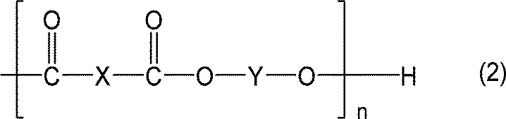
(式は平均の組成を表し、式中の、nは1~5の数を表し、Xは置換および/または非置換の、1,2-フェニレン基、1,2-ナフチレン基、2,3-ナフチレン基、2,3-アントラキノンジイル基、及び2,3-アントラセンジイル基からなる群から選ばれる1種または2種以上であり、Yは炭素原子数2~6のアルキレン基を表す。)
―イソシアネート化合物―
1分子内にイソシアネート基を2個以上有するイソシアネート化合物は、分子内にイソシアネート基を2個以上有していれば、芳香族または脂肪族のどちらでもよく、低分子化合物または高分子化合物のどちらでもよい。例えば、イソシアネート基が2個のジイソシアネート化合物や、3個以上のポリイソシアネート化合物等の公知の化合物が使用できる。または、イソシアネートブロック化剤を用いて汎用の方法より付加反応させて得られたブロック化イソシアネート化合物を用いることもできる。
上記の中でも、イソシアネート化合物は、主骨格に、芳香族環構造部、および/または芳香族環を含むポリウレタン構造部を含むものが好ましい。
接着性の観点からは、ポリイソシアネート化合物が好ましく、ガスバリア性の観点からは、芳香族環を有するものが好ましい。特に、メタキシレン骨格を含むイソシアネート化合物が、ウレタン基の水素結合だけでなく芳香環同士のπ-πスタッキングによってガスバリア性を向上させることが期待されて、好ましい。
1分子内にイソシアネート基を2個以上有するイソシアネート化合物の具体的としては、テトラメチレンジイソシアネート、ヘキサメチレンジイソシアネート、トルエンジイソシアネート、ジフェニルメタンジイソシアネート、水素化ジフェニルメタンジイソシアネート、メタキシリレンジイソシアネート、水素化キシリレンジイソシアネート及びイソホロンジイソシアネート;前述したイソシアネート化合物の3量体;前述したイソシアネート化合物の過剰量と、下記(a)~(c)等とを反応して得られるアダクト体、ビュレット体及びアロファネート体;等が挙げられる。
(a)エチレングリコール、プロピレングリコール、メタキシリレンアルコール、1,3-ビスヒドロキシエチルベンゼン、1,4-ビスヒドロキシエチルベンゼン、トリメチロールプロパン、グリセロール、ペンタエリスリトール、エリスリトール、ソルビトール、エチレンジアミン、モノエタノールアミン、ジエタノールアミン、トリエタノールアミン及びメタキシリレンジアミン等の低分子活性水素化合物。
(b)前記低分子活性水素化合物のアルキレンオキシド付加物。
(c)ポリエステル樹脂類、ポリエーテルポリオール類及びポリアミド類等の高分子活性水素化合物。
(a)エチレングリコール、プロピレングリコール、メタキシリレンアルコール、1,3-ビスヒドロキシエチルベンゼン、1,4-ビスヒドロキシエチルベンゼン、トリメチロールプロパン、グリセロール、ペンタエリスリトール、エリスリトール、ソルビトール、エチレンジアミン、モノエタノールアミン、ジエタノールアミン、トリエタノールアミン及びメタキシリレンジアミン等の低分子活性水素化合物。
(b)前記低分子活性水素化合物のアルキレンオキシド付加物。
(c)ポリエステル樹脂類、ポリエーテルポリオール類及びポリアミド類等の高分子活性水素化合物。
イソシアネート化合物としては、これらの中でも、メタキシレンジイソシアネート、又はメタキシレンジイソシアネートと2個以上の水酸基を有するアルコールとの反応生成物が好ましい。
―リン酸化合物―
リン酸化合物としては、リン酸類および/またはリン酸有機エステルを用いることができ、モノマーであっても、ポリマーであってもよい。リン酸化合物は、リン原子に接続した水酸基を有していることが好ましい。リン酸化合物は、無機蒸着層を保護する接着剤の密着性を高めることができる。
リン酸化合物としては、リン酸類および/またはリン酸有機エステルを用いることができ、モノマーであっても、ポリマーであってもよい。リン酸化合物は、リン原子に接続した水酸基を有していることが好ましい。リン酸化合物は、無機蒸着層を保護する接着剤の密着性を高めることができる。
リン酸類は、リン酸や、ピロリン酸またはポリリン酸のようなリン酸の多量体を指す。
リン酸有機エステルの有機基は、アルキル基、ポリアルキレンエーテル基、(メタ)アクリロイル基、置換または非置換フェニル基からなる群から選ばれる1種または2種以上であることが好ましい。
リン酸有機エステルの有機基は、アルキル基、ポリアルキレンエーテル基、(メタ)アクリロイル基、置換または非置換フェニル基からなる群から選ばれる1種または2種以上であることが好ましい。
無機蒸着層を保護する接着剤中のリン酸化合物の含有量は、0.005質量%以上10質量%以下が好ましく、0.01質量%以上1%質量%以下がより好ましい。
上記範囲より少ない場合、リン酸化合物を含有した効果を得難い場合があり、上記範囲よりも多くても、含有した効果はさほど向上せず、他の成分の含有量が少なることの悪影響が出やすくなる虞がある。
上記範囲より少ない場合、リン酸化合物を含有した効果を得難い場合があり、上記範囲よりも多くても、含有した効果はさほど向上せず、他の成分の含有量が少なることの悪影響が出やすくなる虞がある。
リン酸化合物としては、例えば下記式(3)または(4)で表される化合物が挙げられる。
リン酸化合物の具体例としては、リン酸、ピロリン酸、トリリン酸、メチルアシッドホスフェート、エチルアシッドホスフェート、ブチルアシッドホスフェート、ジブチルホスフェート、2-エチルヘキシルアシッドホスフェート、ビス(2-エチルヘキシル)ホスフェート、イソドデシルアシッドホスフェート、ブトキシエチルアシッドホスフェート、オレイルアシッドホスフェート、テトラコシルアシッドホスフェート、2-ヒドロキシエチルメタクリレートアシッドホスフェート及びポリオキシエチレンアルキルエーテルリン酸等が挙げられる。
リン酸化合物の具体例としては、リン酸、ピロリン酸、トリリン酸、メチルアシッドホスフェート、エチルアシッドホスフェート、ブチルアシッドホスフェート、ジブチルホスフェート、2-エチルヘキシルアシッドホスフェート、ビス(2-エチルヘキシル)ホスフェート、イソドデシルアシッドホスフェート、ブトキシエチルアシッドホスフェート、オレイルアシッドホスフェート、テトラコシルアシッドホスフェート、2-ヒドロキシエチルメタクリレートアシッドホスフェート及びポリオキシエチレンアルキルエーテルリン酸等が挙げられる。
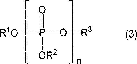
(式は平均の化学構造を表し、式中の、R1、R2、R3は、水素原子、炭素数1~30のアルキル基、(メタ)アクリロイル基、置換または非置換フェニル基、(メタ)アクリロイルオキシ基を有する炭素数1~4のアルキル基からなる群から選ばれる1種または2種以上であり、少なくとも一つは水素原子であり、nは1~4の数を表す。)

(式は平均の化学構造を表し、式中の、R4、R5は、水素原子、炭素数1~30のアルキル基、(メタ)アクリロイル基、置換または非置換フェニル基、(メタ)アクリロイルオキシ基を有する炭素数1~4のアルキル基からなる群から選ばれる1種または2種以上であり、n1、n2は1~4の数、xは0~30の数、yは0~30の数を表し、x+y>0である。)
―無機化合物―
無機蒸着層を保護する接着剤は、無機化合物を含有していてもよい。無機化合物を含有することによって酸素バリア性を向上させることができる。
無機蒸着層を保護する接着剤は、無機化合物を含有していてもよい。無機化合物を含有することによって酸素バリア性を向上させることができる。
無機蒸着層を保護する接着剤中の無機化合物の含有量は、5質量%以上50質量%以下が好ましい。無機化合物の含有量を5質量%以上とすることにより、上述の板状無機化合物による効果を発揮しやすくできる。また、無機化合物の含有量を50質量%以下とすることにより、接着力が低下することを抑制しやすくできる。
無機化合物の形状は特に制限されないが、板状の形状が好ましい。
また、無機化合物のアスペクト比は3以上が好ましく、10以上がより好ましく、40以上がさらに好ましい。また、無機化合物のアスペクト比は500以下が好ましい。
また、無機化合物のアスペクト比は3以上が好ましく、10以上がより好ましく、40以上がさらに好ましい。また、無機化合物のアスペクト比は500以下が好ましい。
無機化合物は、接着剤の粘度の増加の抑制、及び接着剤のチキソ性の上昇の抑制の観点から、水による膨潤性が低く、非イオン性で無電荷であるものが好ましい。特に、無機化合物が板状の形状の場合に、無機化合物が前記性質を示すことが好ましい。
板状無機化合物としては、例えば、フィロケイ酸塩鉱物等の含水ケイ酸塩、ハロイサイト、カオリナイト、エンデライト、ディッカイト、ナクライト等、アンチゴライト、クリソタイル等のカオリナイト-蛇紋族粘土鉱物、パイロフィライト、タルク、ケロライ等のパイロフィライト-タルク族、モンモリロナイト、バイデライト、ノントロナイト、サポナイト、ヘクトライト、ソーコナイト、スチブンサイト等のスメクタイト族粘土鉱物、バーミキュライト等のバーミキュライト族粘土鉱物、白雲母、金雲母等の雲母、マーガライト、テトラシリリックマイカ、テニオライト等の雲母又はマイカ族粘土鉱物、クッケアイト、スドーアイト、クリノクロア、シャモサイト、ニマイト等の緑泥石族、ハイドロタルサイト、板状硫酸バリウム、ベーマイト、ポリリン酸アルミニウム等が挙げられる。上記の板状無機化合物は天然粘土鉱物であっても合成粘土鉱物であってもよく、1種または2種以上を組み合わせて用いてもよい。
上記の中でも、カオリナイト-蛇紋族粘土鉱物、パイロフィライト-タルク族、雲母又はマイカ族粘土鉱物、緑泥石族、ハイドロタルサイト、板状硫酸バリウムは、水に対して非膨潤性であることから好ましく、カオリナイト-蛇紋族粘土鉱物とパイロフィライト-タルク族は、さらに層間電化を持たない非イオン性であることからより好ましい。
上記の中でも、カオリナイト-蛇紋族粘土鉱物、パイロフィライト-タルク族、雲母又はマイカ族粘土鉱物、緑泥石族、ハイドロタルサイト、板状硫酸バリウムは、水に対して非膨潤性であることから好ましく、カオリナイト-蛇紋族粘土鉱物とパイロフィライト-タルク族は、さらに層間電化を持たない非イオン性であることからより好ましい。
無機化合物の平均粒子径は特に限定はないが、0.1μm以上100μm以下が好ましく、1μm以上20μm以下がより好ましい。平均粒子径を0.1μm以上とすることにより、上述の板状無機化合物による効果を発揮しやすくできる。また、平均粒子径を100μm以下とすることにより、塗工性の低下を抑制しやすくできる。
本明細書において、平均粒子径は、レーザー光回折法による粒度分布測定における質量平均値d50を意味する。
本明細書において、平均粒子径は、レーザー光回折法による粒度分布測定における質量平均値d50を意味する。
無機蒸着層を保護する接着剤の市販品としては、DIC(株)社製の、溶剤型バリア性接着剤パスリム(主剤VM001/硬化剤108CP)や、無溶剤型バリア性接着剤パスリム(主剤NSRD011/硬化剤NSRD006)等が知られている。
接着剤層は、接着剤層を構成する成分を含む塗布液を、紙基材層上、無機蒸着層上(無機蒸着層供与体の無機蒸着層上)、又は、セパレータ上に塗布、乾燥し、必要に応じて硬化することにより形成することができる。
<無機蒸着層>
無機蒸着層は、接着剤層の紙基材層とは反対側に位置する。また、無機蒸着層は、接着剤層と接している。言い換えると、無機蒸着層と接着剤層との間には、他の層を有していない。
無機蒸着層は、接着剤層の紙基材層とは反対側に位置する。また、無機蒸着層は、接着剤層と接している。言い換えると、無機蒸着層と接着剤層との間には、他の層を有していない。
無機蒸着層は、接着剤層の紙基材層とは反対側の面上の略全面に有することが好ましい。「略全面」とは、接着剤層の紙基材層とは反対側の面積の95%以上を意味し、好ましくは97%以上、より好ましくは99%以上、最も好ましくは100%である。
本実施形態のバリア紙は、無機蒸着層の紙基材層とは反対側の面の算術平均粗さをRa1、前記Ra1の標準偏差をσRa1と定義した際に、σRa1が0.030μm以下であることが好ましい。
本明細書において、算術平均粗さとは、JIS B0601:2001に規定する算術平均粗さRaを意味する。但し、算術平均粗さを算出する際のカットオフλs及びカットオフλcは何れも「0」とする。
本明細書において、算術平均粗さとは、JIS B0601:2001に規定する算術平均粗さRaを意味する。但し、算術平均粗さを算出する際のカットオフλs及びカットオフλcは何れも「0」とする。
無機蒸着層の紙基材層とは反対側の面は、図1~4のXの面を意味する。図1~3は、本発明のバリア紙の一実施形態を示す概略断面図であり、図4は、従来のバリア紙の一実施形態を示す概略断面図である。
以下、無機蒸着層の紙基材層とは反対側の面のことを「面X」と称する場合がある。
以下、無機蒸着層の紙基材層とは反対側の面のことを「面X」と称する場合がある。
σRa1を0.030μm以下とすることにより、バリア性を良好にしやすくできる。この理由は以下のように考えられる。
まず、σRa1が0.030μmを超えることは、無機蒸着層の紙基材層とは反対側の面の算術平均粗さの値が、場所ごとに大きく異なることを意味している。無機蒸着層の算術平均粗さの値が場所ごとで大きく異なる場合、無機蒸着層の物理特性も場所ごと異なりやすくなる。このため、σRa1が0.030μmを超える場合、無機蒸着層の面内の局所的な領域において、バリア性が小さくなる箇所が生じやすくなると考えられる。そして、局所的にバリア性が弱い領域から水蒸気又はガスが透過する結果、σRa1が0.030μmを超えるバリア紙は、バリア性を良好にしにくいと考えられる。
一方、σRa1が0.030μm以下であると、無機蒸着層の面内の局所的な領域において、バリア性が小さくなる箇所が生じにくくなる。このため、σRa1が0.030μm以下のバリア紙は、バリア性を良好にやすいと考えられる。
σRa1は、0.025μm以下であることが好ましく、0.022μm以下であることがより好ましく、0.020μm以下であることがさらに好ましい。
σRa1の下限は特に制限されないが、0.001μm以上であることが好ましく、0.002μm以上であることがより好ましく、0.005μm以上であることがさらに好ましい。
σRa1の下限は特に制限されないが、0.001μm以上であることが好ましく、0.002μm以上であることがより好ましく、0.005μm以上であることがさらに好ましい。
本明細書において、Ra1は72箇所の算術平均粗さRaの平均値を意味する。また、本明細書においてσRa1は、72箇所の算術平均粗さRaの標準偏差(標準偏差1σ)を意味する。
本明細書において、Ra1、σRa1及び後述するRku等の表面形状に関するパラメータを算出する72の測定箇所は、測定サンプルの外縁から1cmの領域を余白として、該余白よりも内側の領域を縦方向及び横方向に6等分した36の領域内で行うことが好ましい。具体的には、前記36の領域内において、縦方向及び横方向の表面形状を測定し、72(36箇所×2方向=72箇所の測定値)の測定値を得る。表面形状は36の領域内の中央近傍で測定することが好ましい。なお、測定サンプルは、折り曲げ部を除いてサンプリングすることが好ましい(例えば、バリア紙を用いて形成されてなる容器からサンプリングする場合、折り曲げ部を除いてサンプリングすることが好ましい。)。
測定サンプルが四角形の場合、図5に示すように、四角形の外縁から1cmの領域を余白として、該余白よりも内側の領域を縦方向及び横方向に6等分した36の領域内で測定する。そして、前記36の領域内で、縦方向及び横方向の表面形状を測定し、72の測定値を得る。そして、72の測定値の平均からRa1を算出し、72の測定値の標準偏差(標準偏差1σ)からσRa1を算出する。なお、測定サンプルが円形、楕円形、三角形、五角形等の四角形以外の形状の場合、これら形状に内接する四角形を描き、該四角形に関して、上記手法により72の測定値を得ることが好ましい。
測定サンプルが四角形の場合、図5に示すように、四角形の外縁から1cmの領域を余白として、該余白よりも内側の領域を縦方向及び横方向に6等分した36の領域内で測定する。そして、前記36の領域内で、縦方向及び横方向の表面形状を測定し、72の測定値を得る。そして、72の測定値の平均からRa1を算出し、72の測定値の標準偏差(標準偏差1σ)からσRa1を算出する。なお、測定サンプルが円形、楕円形、三角形、五角形等の四角形以外の形状の場合、これら形状に内接する四角形を描き、該四角形に関して、上記手法により72の測定値を得ることが好ましい。
無機蒸着層の紙基材層とは反対側の面の表面形状は、例えば、非接触式の表面形状測定器で測定できる。非接触式の表面形状測定器は、共焦点方式及び白色干渉方式等が挙げられる。本実施形態では、非接触式の表面形状測定器の中でも共焦点方式で表面形状を測定している。
図2及び図3のように、無機蒸着層の紙基材層とは反対側の面(面X)が表面に露出していない場合には、共焦点方式の表面形状測定器の光の焦点を面Xに合わせることにより、面Xの表面形状を測定することができる。
共焦点方式の表面形状測定器としては、例えば、キーエンス社の商品名「VK-X150」が挙げられる。
図2及び図3のように、無機蒸着層の紙基材層とは反対側の面(面X)が表面に露出していない場合には、共焦点方式の表面形状測定器の光の焦点を面Xに合わせることにより、面Xの表面形状を測定することができる。
共焦点方式の表面形状測定器としては、例えば、キーエンス社の商品名「VK-X150」が挙げられる。
共焦点方式の表面形状測定器では、任意の面積の表面形状を測定することができる。そして、測定した任意の面積内において、任意の位置の横方向を選択すれば、当該位置の横方向のRa1を算出することができ、任意の位置の縦方向を選択すれば、当該位置の縦方向の算術平均粗さを算出することができる。上記の共焦点方式の表面形状測定器(キーエンス社の商品名「VK-X150」)の場合、2次元表示された表面形状の画面上において、任意の位置の横方向又は任意の位置の縦方向を選択することにより、選択した方向の算術平均粗さを算出することができる。
個々の測定における測定領域の大きさは特に制限されないが、下限は縦100μm×横100μm以上とすることが好ましく、上限は縦500μm×横500μm以下とすることが好ましい。
個々の測定における測定領域の大きさは特に制限されないが、下限は縦100μm×横100μm以上とすることが好ましく、上限は縦500μm×横500μm以下とすることが好ましい。
本明細書において、Ra1及びσRa1は、例えば、下記(A1)~(A4)の手順で算出することができる。後述するRku1も、例えば、下記(A1)~(A4)と同様の手順で算出することができる(但し、下記(A3)及び(A4)の「算術平均粗さ」を「粗さ曲線のクルトシス」に読み替え、下記(A4)の「Ra1」を「Rku1」に読み替える。)。
(A1)上記のように測定サンプルを36の領域に区分けする。
(A2)共焦点方式の表面形状測定器を用いて、36の領域内の中央近傍の任意の面積の表面形状を測定する。
(A3)上記(A2)で測定された任意の面積の表面形状データに基づいて、36の領域内の横方向の算術平均粗さRa及び縦方向の算術平均粗さRaを算出する。ここまでの作業で、72(36箇所×2方向=72箇所の測定値)の算術平均粗さRaが得られる。
(A4)72箇所の算術平均粗さRaの平均値を算出し、算出した平均値を当該サンプルのRa1とする。また、72箇所の算術平均粗さRaの標準偏差を算出し、算出した標準偏差を当該サンプルのσRa1とする。
(A1)上記のように測定サンプルを36の領域に区分けする。
(A2)共焦点方式の表面形状測定器を用いて、36の領域内の中央近傍の任意の面積の表面形状を測定する。
(A3)上記(A2)で測定された任意の面積の表面形状データに基づいて、36の領域内の横方向の算術平均粗さRa及び縦方向の算術平均粗さRaを算出する。ここまでの作業で、72(36箇所×2方向=72箇所の測定値)の算術平均粗さRaが得られる。
(A4)72箇所の算術平均粗さRaの平均値を算出し、算出した平均値を当該サンプルのRa1とする。また、72箇所の算術平均粗さRaの標準偏差を算出し、算出した標準偏差を当該サンプルのσRa1とする。
σRa1を0.030μm以下としやすくするためには、紙基材層の粗さが無機蒸着層に反映されることを抑制することが好ましい。このため、紙基材層と無機蒸着層との間には、接着剤層を配置することが好ましく、目止め層及び接着剤層を配置することがより好ましい。
また、σRa1を0.030μm以下としやすくするためには、転写法により無機蒸着層を形成し、かつ、離型性を有する支持体として表面形状が略平滑な支持体を用いることが好ましい。前述のように形成した無機蒸着層は、離型性を有する支持体の略平滑な表面形状が反映されるため、σRa1を小さくしやすくできる。
上述したσRa1を小さくしやすくするための手段は、Ra1を後述する範囲としやすくする手段、及び、Rkuを後述する範囲としやすくする手段としても有用である。
また、σRa1を0.030μm以下としやすくするためには、転写法により無機蒸着層を形成し、かつ、離型性を有する支持体として表面形状が略平滑な支持体を用いることが好ましい。前述のように形成した無機蒸着層は、離型性を有する支持体の略平滑な表面形状が反映されるため、σRa1を小さくしやすくできる。
上述したσRa1を小さくしやすくするための手段は、Ra1を後述する範囲としやすくする手段、及び、Rkuを後述する範囲としやすくする手段としても有用である。
本実施形態のバリア紙は、Ra1が0.100μm以下であることが好ましい。Ra1を0.100μm以下とすることにより、σRa1を0.030μm以下とすることによる効果をより発揮しやすくできる。
Ra1は0.080μm以下であることがより好ましく、0.070μm以下であることがより好ましく、0.065μm以下であることがより好ましい。
Ra1は0.080μm以下であることがより好ましく、0.070μm以下であることがより好ましく、0.065μm以下であることがより好ましい。
Ra1の下限は特に制限されないが、0.001μm以上であることが好ましく、0.002μm以上であることがより好ましく、0.005μm以上であることがさらに好ましい。
本実施形態のバリア紙は、σRa1/Ra1が0.40以下であることが好ましく、0.30以下であることがより好ましい。σRa1/Ra1を0.40以下とすることにより、σRa1を0.030μm以下とすることによる効果をより発揮しやすくできる。
σRa1/Ra1は、標準偏差を平均値で除した無次元の値であり、いわゆる変動係数である。
σRa1/Ra1は、標準偏差を平均値で除した無次元の値であり、いわゆる変動係数である。
本実施形態のバリア紙は、無機蒸着層の紙基材層とは反対側の面の粗さ曲線のクルトシスをRku1と定義した際に、Rku1が3.0超であることが好ましい。表面形状の高さ分布を、低い箇所、平均的な箇所、高い箇所に区分した場合、Rku1が3.0を超えることは、平均的な箇所が多く、低い箇所及び高い箇所が少ないことを意味する。したがって、Rku1が3.0を超えることにより、無機蒸着層の面内の局所的な領域でバリア性が小さくなることを抑制し、バリア性を良好にしやすくできる。
Rku1は、5.0以上であることがより好ましく、7.5以上であることがより好ましく、10.0以上であることがより好ましい。
Rku1は、5.0以上であることがより好ましく、7.5以上であることがより好ましく、10.0以上であることがより好ましい。
Rku1の上限は特に制限されないが、30.0以下であることが好ましく、25.0以下であることがより好ましく、20.0以下であることがさらに好ましい。
本明細書において、Rku1は72箇所の粗さ曲線のクルトシスの平均値を意味する。
また、本明細書において、粗さ曲線のクルトシスとは、JIS B0601:2001に規定する粗さ曲線のクルトシスRkuを意味する。但し、算術平均粗さを算出する際のカットオフλs及びカットオフλcは何れも「0」とする。
また、本明細書において、粗さ曲線のクルトシスとは、JIS B0601:2001に規定する粗さ曲線のクルトシスRkuを意味する。但し、算術平均粗さを算出する際のカットオフλs及びカットオフλcは何れも「0」とする。
無機蒸着層の形成方法としては、真空蒸着法、スパッタリング法、イオンプレーティング法等の物理的気相蒸着法(PVD)、プラズマ化学気相成長法、熱化学気相成長法、光化学気相成長法等の化学気相成長法(CVD)が挙げられる。
無機蒸着層は、透明であってもよいし不透明であってもよい。無機蒸着層が不透明であれば、バリア紙に遮光性を付与し、内容物の品質を維持しやすくできる。無機蒸着層が透明であれば、電子レンジで使用しやすい点、内容物充填後に金属探知機で検査しやすい点、印刷層の色が沈んだ色となりにくい点で好ましい。
無機蒸着層を構成する無機化合物としては、金属、金属酸化物、金属窒化物、金属炭化物等が挙げられる。無機蒸着層を構成する無機化合物は、2種以上の無機化合物を混合してもよい。
無機蒸着層を構成する無機化合物としては、金属、金属酸化物、金属窒化物、金属炭化物等が挙げられる。無機蒸着層を構成する無機化合物は、2種以上の無機化合物を混合してもよい。
上記の無機化合物を構成する金属元素の具体例としては、例えば、アルミニウム(Al)、ケイ素(Si)、マグネシウム(Mg)、カルシウム(Ca)、カリウム(K)、スズ(Sn)、ナトリウム(Na)、ホウ素(B)、チタン(Ti)、鉛(Pb)、ジルコニウム(Zr)、イットリウム(Y)、亜鉛(Zn)、バナジウム(V)、バリウム(Ba)、クロム(Cr)等が挙げられる。
無機化合物の具体例としては、上記金属、上記金属の酸化物、上記金属の窒化物、上記金属の炭化物が挙げられ、さらに、酸化インジウム錫(ITO)、SiOxCy膜などの複合的な無機化合物も挙げられる。金属の酸化物は、無機蒸着層を透明にしやすく、また、化学的に安定な傾向である点で好ましい。また、金属の酸化物は、電子レンジで使用しやすい点、内容物充填後に金属探知機で検査しやすい点、印刷層の色が沈んだ色となりにくい点において好ましい。
無機化合物の中でも、アルミニウム、酸化アルミニウム、酸化珪素が好ましく、酸化アルミニウム及び酸化珪素がより好ましい。
無機化合物の中でも、アルミニウム、酸化アルミニウム、酸化珪素が好ましく、酸化アルミニウム及び酸化珪素がより好ましい。
無機化合物の平均組成の表記は、例えば、SiOx、AlOx、SiOxCy等のようにMOx、MOxCyで表される(ただし、式中、Mは金属元素を表し、x、yの値は、金属元素によってそれぞれ範囲が異なる。)。金属酸化物の場合、xの値の範囲は、ケイ素は、0~2、アルミニウムは、0~1.5、マグネシウムは、0~1、カルシウムは、0~1、カリウムは、0~0.5、スズは、0~2、ナトリウムは、0~0.5、ホウ素は、0~1、5、チタンは、0~2、鉛は、0~1、ジルコニウムは0~2、イットリウムは、0~1.5の範囲の値をとることができる。
上記のMOxにおいて、x=0の場合は金属である。また、xの範囲の上限は、完全に酸化した場合の値である。
本実施形態においては、酸化アルミニウムはxが0.5~1.5の範囲の値のものが好ましく、酸化珪素はxが1.0~2.0の範囲の値のものが好ましい。
上記のMOxにおいて、x=0の場合は金属である。また、xの範囲の上限は、完全に酸化した場合の値である。
本実施形態においては、酸化アルミニウムはxが0.5~1.5の範囲の値のものが好ましく、酸化珪素はxが1.0~2.0の範囲の値のものが好ましい。
無機蒸着層は、1層で構成されていてもよく、同一または異なる組成の多層によって構成されていてもよい。
無機蒸着層の厚みは、30Å以上3000Å以下が好ましく、40Å以上2500Å以下がより好ましく、50Å以上2000Å以下がさらに好ましい。無機蒸着層の厚みを30Å以上とすることにより、バリア性を良好にしやすくでき、無機蒸着層の厚みを3000Å以下とすることにより、無機蒸着層にクラックが生じることを抑制しやすくできる。
更に詳しくは、上記のPVD法においては、酸化アルミニウムからなる無機蒸着層の厚さは、30Å以上1000Å以下が好ましく、50Å以上500Å以下がより好ましい。
また、上記のCVD法においては、酸化珪素からなる無機蒸着層の厚さは、30Å以上3000Å以下が好ましく、100Å以上300Å以下がより好ましい。
更に詳しくは、上記のPVD法においては、酸化アルミニウムからなる無機蒸着層の厚さは、30Å以上1000Å以下が好ましく、50Å以上500Å以下がより好ましい。
また、上記のCVD法においては、酸化珪素からなる無機蒸着層の厚さは、30Å以上3000Å以下が好ましく、100Å以上300Å以下がより好ましい。
無機蒸着層は、例えば、「接着剤層上に直接無機化合物を蒸着して形成する手法(直接蒸着法)」、「転写法」により形成することができる。
転写法は、離型性を有する支持体上に無機蒸着層を有する無機蒸着層供与体と、紙基材層とを、接着剤層を介して貼り合わせて、紙基材層上に無機蒸着層を転写により形成する手法である。
直接蒸着法と転写法とを対比すると、転写法は、紙基材層が蒸着雰囲気に晒されることによる不具合が生じず、接着剤層と無機蒸着層との密着性を良好にしやすい点で好ましい。また、転写法は、Ra1、σRa1及びRku1を上述した範囲にしやすくできる点で好ましい。
転写法は、接着剤層の形成の仕方により、「1.無機蒸着層供与体の無機蒸着層上に接着剤層を形成するタイプ」、「2.紙基材層上に接着剤層を形成するタイプ」、「3.無機蒸着層供与体の無機蒸着層上、及び紙基材上の両方に接着剤層を形成するタイプ」、「4.紙基材層と無機蒸着層供与体との間に接着剤層を供給するタイプ」が挙げられる。これらの中でも、「2」及び「4」のタイプが好ましい。無機蒸着層上に接着剤層等の他の層を形成する際には無機蒸着層に欠陥が生じる可能性があるが、「2」及び「4」のタイプは前述した可能性を排除できるためである。また、「2」及び「4」の中でも、紙基材層と接着剤層との密着性を良好にしやすい「2」が好ましい。
接着剤層と無機蒸着層との間の層間密着強度は、JIS K5600-5-6に則ったクロスカット試験において、分類0、1及び2の何れかであることが好ましく、分類0及び1の何れかであることがより好ましい。上記範囲よりも低い分類3、4または5であると、接着剤層と無機蒸着層との間で剥離が生じてガスバリア性が低下し易い。
上記の層間密着強度の評価の概略は下記のとおりである。
バリア紙上の無機蒸着層に、カッターナイフ等で無機蒸着層を貫通して切り込み、複数個の直角の格子パターンを形成する。この際、複数個の直角の格子パターンを連続してきれいに形成し得るようなクロスカット用治具を用いることが好ましい。
次に、接着用セロハンテープ等のような片面に粘着剤層を有する接着テープを、上記で形成した全格子を覆うように貼り付ける。
そして、テンシロンを用いて、貼り付けた接着テープを端から剥離し、無機蒸着層の剥がれ具合を目視で観察して、下記の評価基準で結果を分類する。
格子パターンの1辺のサイズは、1mm以上5mm以下が好ましく、1.5mm以上3mm以下がより好ましい、2mm程度がさらに好ましい。格子パターンの個数は、15個以上50個以下が好ましく、20個以上30個以下がより好ましく、25個程度がさらに好ましい。接着テープの幅と長さは、形成した格子パターンの全てを覆えて、かつ剥がし易いサイズが好ましい。接着テープの剥離は、テンシロン等を用いて、好ましくは1mm/分以上5mm/分以下、より好ましくは2mm/分以上4mm/分以下、さらに好ましくは3mm/分程度の等速度で行う。
分類0:カットの縁が完全に滑らかで、どの格子の目にも剥がれが無い。
分類1:カットの交差点における塗膜の小さな剥がれがある。但しクロスカット部分で影響を受けるのは、明確に5%を上回ることはない。
分類2:塗膜のカットの縁に沿って、及び/又は交差点において剥がれがある。クロスカット部分で影響を受けるのは明確に5%以上15%以下の間。
分類3:塗膜がカットの縁に沿って、部分的、又は全面的に大剥がれを生じており、及び/又は目の色々な部分が、部分的に、又は全面的にはがれている。クロスカット部分で影響を受けるのは15%を超え、35%を下回る範囲。
分類4:塗膜がカットの縁に沿って、部分的または全面的に大剥がれを生じており、および又は、数か所の目が部分的又は全面的にはがれている。クロスカット部分で影響を受けるのは明確に35%を上回ることがない範囲。
分類5:分類4でも分類できない剥がれ程度のいずれか。
<目止め層>
本実施形態のバリア紙は、紙基材層と接着剤層との間に目止め層を有することが好ましい。目止め層を有することにより、接着剤層の厚みの標準偏差及び変動係数を上述した範囲にしやすくできる。また、紙基材層と無機蒸着層との間に、接着剤層に加えて目止め層を有することにより、σRa1等の表面形状を上述した範囲にしやすくできる。
目止め層としては、クレーコート層及び樹脂層が挙げられる。
本実施形態のバリア紙は、紙基材層と接着剤層との間に目止め層を有することが好ましい。目止め層を有することにより、接着剤層の厚みの標準偏差及び変動係数を上述した範囲にしやすくできる。また、紙基材層と無機蒸着層との間に、接着剤層に加えて目止め層を有することにより、σRa1等の表面形状を上述した範囲にしやすくできる。
目止め層としては、クレーコート層及び樹脂層が挙げられる。
クレーコート層は、クレー及びバインダーを含むことが好ましい。
クレーとしては、一般的にクレーと呼ばれるものであれば、特に限定することなく用いることができる。クレーの具体例としては、カオリン、タルク、ベントナイト、スメクタイト、バーミキュライト、雲母、緑泥石、木節粘土、ガイロメ粘土、ハロイサイト、マイカ等が挙げられる。タルクは硬度が低く(モース硬度1)、耐熱性に優れるため、耐熱性の向上やエンボス加工時の寸法安定性を向上させることができる。
クレーとしては、一般的にクレーと呼ばれるものであれば、特に限定することなく用いることができる。クレーの具体例としては、カオリン、タルク、ベントナイト、スメクタイト、バーミキュライト、雲母、緑泥石、木節粘土、ガイロメ粘土、ハロイサイト、マイカ等が挙げられる。タルクは硬度が低く(モース硬度1)、耐熱性に優れるため、耐熱性の向上やエンボス加工時の寸法安定性を向上させることができる。
バインダーとしては、通常、ラテックス系のバインダー(例えば、スチレンブタジエンラテックス、アクリル系ラテックス酢酸ビニル系ラテックス)、水溶性のバインダー(例えば、デンプン(変性デンプン、酸化デンプン、ヒドロキシエチルエーテル化デンプン、リン酸エステル化デンプン)、ポリビニルアルコール、カゼイン等)が挙げられる。
クレーコート層は、クレーコート層の表面の平滑性向上のため、炭酸カルシウム、二酸化チタン、非晶質シリカ、発泡性硫酸バリウム、サチンホワイト等の顔料を含むことが好ましい。顔料の中でも、炭酸カルシウム及び二酸化チタンが好ましく、炭酸カルシウムがより好ましい。
クレーコート層は、さらに、顔料分散剤、消泡剤、発泡防止剤、粘度調整剤、潤滑剤、耐水化剤、保水剤等の添加剤を含有していてもよい。
クレーコート層は、さらに、顔料分散剤、消泡剤、発泡防止剤、粘度調整剤、潤滑剤、耐水化剤、保水剤等の添加剤を含有していてもよい。
クレーコート層の厚みは、乾燥後の坪量が5g/m2以上40g/m2以下であることが好ましく、10g/m2以上40g/m2以下であることがより好ましい。乾燥後の坪量を5g/m2以上とすることにより、上述した目止め層の効果を発揮しやすくできる。また、乾燥後の坪量を40g/m2以下とすることにより、クレーコート層の凝集破壊を抑制しやすくできる。また、クレーコート層の厚みは、3μm以上40μm以下が好ましく、10μm以上30μm以下がより好ましい。
クレーコート層は、例えば、紙基材層上に、クレーコート層を構成する成分を含む塗布液を汎用の塗布方法により塗布、乾燥することにより、形成することができる。クレーコート層塗布液の溶媒としては、水、アルコール等が挙げられる。
クレーコート層は、例えば、紙基材層上に、クレーコート層を構成する成分を含む塗布液を汎用の塗布方法により塗布、乾燥することにより、形成することができる。クレーコート層塗布液の溶媒としては、水、アルコール等が挙げられる。
樹脂層を構成する樹脂としては、ポリオレフィン系樹脂、アクリル系樹脂、ウレタン系樹脂、PVA(ポリビニルアルコール)などが挙げられる。樹脂層は、例えば、紙基材層上にコーティングすることにより形成できる。
樹脂層の厚みは、上述した目止め層の効果を発揮しやすくため、10μm以上であることが好ましい。また、樹脂層の厚みは、リサイクル性のため、60μm以下が好ましい。
樹脂層の厚みは、上述した目止め層の効果を発揮しやすくため、10μm以上であることが好ましい。また、樹脂層の厚みは、リサイクル性のため、60μm以下が好ましい。
<剥離層、保護層、ヒートシール層、シーラント層>
本実施形態のバリア紙は、無機蒸着層の接着剤層とは反対側に、剥離層、保護層、ヒートシール層及びシーラント層から選ばれる1以上の層を有することが好ましい。
本実施形態のバリア紙は、無機蒸着層の接着剤層とは反対側に、剥離層、保護層、ヒートシール層及びシーラント層から選ばれる1以上の層を有することが好ましい。
《剥離層》
バリア紙は、無機蒸着層の接着剤層とは反対側に剥離層を有していてもよい。
剥離層は、無機蒸着層供与体から離型性を有する支持体を剥離しやすくするために、必要に応じて設けられる層である。
離型性を有する支持体上に剥離層及び無機蒸着層を無機蒸着層供与体を用いて、紙基材層に対して、接着剤層を介して無機蒸着層及び剥離層を転写した場合には、無機蒸着層の接着剤層とは反対側に剥離層が位置することになる。無機蒸着層の接着剤層とは反対側に剥離層を位置させることにより、剥離層を無機蒸着層の保護層として機能させることができる。
また、剥離層は、離型性を有する支持体の表面形状を平均化かつ平坦化しやすくできる。このため、剥離層を有することにより、σRa1等の表面形状を上述した範囲にしやすくできる。
剥離層は、無機蒸着層の接着剤層とは反対側の面上の略全面に有することが好ましい。「略全面」とは、無機蒸着層の接着剤層とは反対側の面積の95%以上を意味し、好ましくは97%以上、より好ましくは99%以上、最も好ましくは100%である。
剥離層は、無機蒸着層の転写を達成するためのバランスの良い接着強度を発揮するものであれば特に制限は無いが、樹脂および/またはワックスを含有することが好ましい。
樹脂としては、ポリエステル系樹脂、アクリル系樹脂、シリコーン系樹脂、ポリビニルブチラール系樹脂、アセタール系樹脂等が挙げられる。これらの中でも、ポリエステル系樹脂、アクリル系樹脂が好ましい。
ワックスとしては、カルバナワックス、パラフィン系ワックス、ポリエチレン系ワックス、ポリプロピレン系ワックス等が挙げられる。これらの中でも、ポリエチレン系ワックスが好ましい。
樹脂としては、ポリエステル系樹脂、アクリル系樹脂、シリコーン系樹脂、ポリビニルブチラール系樹脂、アセタール系樹脂等が挙げられる。これらの中でも、ポリエステル系樹脂、アクリル系樹脂が好ましい。
ワックスとしては、カルバナワックス、パラフィン系ワックス、ポリエチレン系ワックス、ポリプロピレン系ワックス等が挙げられる。これらの中でも、ポリエチレン系ワックスが好ましい。
剥離層は、σRa1等の表面形状を上述した範囲にしやすくするため、顔料、マット剤等の粒子を実質的に含有しないことが好ましい。実質的に含有しないとは、剥離層を構成する全固形分の0.1質量%以下を意味し、好ましくは0.01質量%以下、より好ましくは0.001質量%以下であり、最も好ましくは0質量%である。
剥離層の塗工量は、0.2g/m2以上5.0g/m2以下が好ましい。また、剥離層の厚みは、0.1μm以上10μm以下が好ましい。
《保護層》
バリア紙は保護層を有していてもよい。保護層は、無機蒸着層を保護するために、無機蒸着層の接着剤層とは反対側に有することが好ましい。
また、保護層は、離型性を有する支持体の表面形状を平均化かつ平坦化しやすくできる。このため、保護層を有することにより、σRa1等の表面形状を上述した範囲にしやすくできる。
バリア紙は保護層を有していてもよい。保護層は、無機蒸着層を保護するために、無機蒸着層の接着剤層とは反対側に有することが好ましい。
また、保護層は、離型性を有する支持体の表面形状を平均化かつ平坦化しやすくできる。このため、保護層を有することにより、σRa1等の表面形状を上述した範囲にしやすくできる。
保護層は、無機蒸着層の接着剤層とは反対側の面上の略全面に有することが好ましい。「略全面」とは、無機蒸着層の接着剤層とは反対側の面積の95%以上を意味し、好ましくは97%以上、より好ましくは99%以上、最も好ましくは100%である。
保護層は、例えば、「1.無機蒸着層上に保護層塗布液を塗布、乾燥すること」、「2.無機蒸着層上に保護層を転写すること」、「3.離型性を有する支持体上に保護層及び無機蒸着層をこの順に有する無機蒸着層供与体を準備し、紙基材層に対して、接着剤層を介して、無機蒸着層及び保護層を転写すること」により形成することができる。これらの中でも、作業性の向上及び無機蒸着層の欠陥抑制のために、「3」が好ましい。
保護層は、樹脂成分の単独であってもよいし、無機成分の単独であってもよいし、樹脂成分と無機成分との混合であってもよい。
一例として、保護層は、水溶性高分子及び金属アルコキシド系化合物から選ばれる1種以上を含むことが好ましい。また、保護層は、水溶性高分子及び金属アルコキシド系化合物のうち、水溶性高分子から選ばれる1種以上を含むことがより好ましく、水溶性高分子から選ばれる1種以上と、金属アルコキシド系化合物から選ばれる1種以上とを含むことがさらに好ましい。
水溶性高分子としては、ポリビニルアルコール、ポリビニルピロリドン、及びエチレン-ビニルアルコール共重合体等が挙げられ、これらの中でもバリア性の観点から、ポリビニルアルコール及びエチレン-ビニルアルコール共重合体が好ましく、ポリビニルアルコールがより好ましい。すなわち、保護層は、ポリビニルアルコール及びエチレン-ビニルアルコール共重合体から選ばれる1種以上を含むことが好ましく、ポリビニルアルコールを含むことがより好ましい。
保護層が、水溶性高分子及び金属アルコキシド系化合物を含有する場合、金属アルコキシド系化合物の合計量100質量部に対する水溶性高分子の含有量は、5質量部以上500質量部以下であることが好ましく、7質量部以上100質量部以下であることがより好ましく、8質量部以上50質量部以下であることがさらに好ましい。
金属アルコキシド系化合物としては、金属アルコキシド、金属アルコキシド加水分解物及び金属アルコキシド重合物が挙げられる。
金属アルコキシドは、M(OR)nの一般式で表される化合物である。式中、Mは、Si、Ti、Al及びZr等の金属を示し、Rは、メチル基及びエチル基等のアルキル基を示す。金属アルコキシドの具体例としては、テトラメトキシシラン、テトラエトキシシラン及びイソプロポキシアルミニウム等が挙げられる。
金属アルコキシドは、M(OR)nの一般式で表される化合物である。式中、Mは、Si、Ti、Al及びZr等の金属を示し、Rは、メチル基及びエチル基等のアルキル基を示す。金属アルコキシドの具体例としては、テトラメトキシシラン、テトラエトキシシラン及びイソプロポキシアルミニウム等が挙げられる。
保護層は、例えば、保護層を構成する成分を含む塗布液を、無機蒸着層供与体の離型性を有する支持体上に塗布、乾燥することにより形成することができる。該塗布液中には、シランカップリング剤、硬化剤及び分散剤等の添加剤を含有してもよい。
保護層は、σRa1等の表面形状を上述した範囲にしやすくするため、顔料、マット剤等の粒子を実質的に含有しないことが好ましい。実質的に含有しないとは、保護層を構成する全固形分の0.1質量%以下を意味し、好ましくは0.01質量%以下、より好ましくは0.001質量%以下であり、最も好ましくは0質量%である。
保護層の厚みは、無機蒸着層を保護してバリア性を良好にしやすくするため、下限が70nm以上であることが好ましく、85nm以上であることがより好ましく、100nm以上であることがさらに好ましい。
また、保護層の厚みは、上限が480nm以下であることが好ましく、400nm以下であることがより好ましく、300nm以下であることがさらに好ましい。保護層の厚みを480nm以下とすることにより、保護層に生じる応力を抑制し、前記応力により無機蒸着層にクラックが生じることを抑制しやすくできる。
また、保護層の厚みは、上限が480nm以下であることが好ましく、400nm以下であることがより好ましく、300nm以下であることがさらに好ましい。保護層の厚みを480nm以下とすることにより、保護層に生じる応力を抑制し、前記応力により無機蒸着層にクラックが生じることを抑制しやすくできる。
《ヒートシール層》
バリア紙はヒートシール層を有していてもよい。ヒートシール層は、無機蒸着層の接着剤層とは反対側に有することが好ましい。また、バリア紙がヒートシール層を有する場合、ヒートシール層から無機蒸着層を保護するため、無機蒸着層とヒートシール層との間には、剥離層及び保護層の少なくとも何れかを有することが好ましい。
ヒートシール層は、例えば、バリア紙を容器の形態にする際の接着剤層としての機能を有する。
バリア紙はヒートシール層を有していてもよい。ヒートシール層は、無機蒸着層の接着剤層とは反対側に有することが好ましい。また、バリア紙がヒートシール層を有する場合、ヒートシール層から無機蒸着層を保護するため、無機蒸着層とヒートシール層との間には、剥離層及び保護層の少なくとも何れかを有することが好ましい。
ヒートシール層は、例えば、バリア紙を容器の形態にする際の接着剤層としての機能を有する。
ヒートシール層は、例えば、汎用の熱可塑性樹脂から形成することができる。ヒートシール層の厚みは、通常15μm以上100μm以下程度である。
ヒートシール層は、例えば、「1.無機蒸着層上にヒートシール層を溶融押し出しすること」、「2.無機蒸着層上にヒートシール層塗布液を塗布、乾燥すること」、「3.無機蒸着層上にヒートシール層を転写すること」、「4.離型性を有する支持体上にヒートシール層及び無機蒸着層をこの順に有する無機蒸着層供与体を準備し、紙基材層に対して、接着剤層を介して、無機蒸着層及びヒートシール層を転写すること」、「5.無機蒸着層上にヒートシール層をドライラミネートすること」により形成することができる。
これらの中でも、無機蒸着層の蒸着コストの低減の観点から、「1」、「2」、「3」及び「5」が好ましい。また、「1」、「2」、「3」及び「5」の場合、無機蒸着層とヒートシール層との間には、剥離層及び保護層の少なくとも何れかを有することが好ましい。また、無機蒸着層とヒートシール層との間に剥離層及び保護層の少なくとも何れかを有する場合には、「1」、「2」、「3」及び「5」の中では、「1」、「2」及び「5」が好ましく、「2」がより好ましい(ヒートシール層塗布液の溶剤を剥離層又は保護層がブロックするため、溶剤により無機蒸着層が劣化することを抑制できる。このため、作業性を考慮すると「2」がより好ましい)。
これらの中でも、無機蒸着層の蒸着コストの低減の観点から、「1」、「2」、「3」及び「5」が好ましい。また、「1」、「2」、「3」及び「5」の場合、無機蒸着層とヒートシール層との間には、剥離層及び保護層の少なくとも何れかを有することが好ましい。また、無機蒸着層とヒートシール層との間に剥離層及び保護層の少なくとも何れかを有する場合には、「1」、「2」、「3」及び「5」の中では、「1」、「2」及び「5」が好ましく、「2」がより好ましい(ヒートシール層塗布液の溶剤を剥離層又は保護層がブロックするため、溶剤により無機蒸着層が劣化することを抑制できる。このため、作業性を考慮すると「2」がより好ましい)。
《シーラント層》
バリア紙はシーラント層を有していてもよい。シーラント層は、無機蒸着層の接着剤層とは反対側に有することが好ましい。また、バリア紙がシーラント層を有する場合、シーラント層から無機蒸着層を保護するため、無機蒸着層とシーラント層との間には、剥離層及び保護層の少なくとも何れかを有することが好ましい。
シーラント層は、例えば、バリア紙を容器として用いた際に、容器に入れられる内容物と、バリア紙の他の層とが接触することを防止し、内容物を保護する機能を有する。
バリア紙はシーラント層を有していてもよい。シーラント層は、無機蒸着層の接着剤層とは反対側に有することが好ましい。また、バリア紙がシーラント層を有する場合、シーラント層から無機蒸着層を保護するため、無機蒸着層とシーラント層との間には、剥離層及び保護層の少なくとも何れかを有することが好ましい。
シーラント層は、例えば、バリア紙を容器として用いた際に、容器に入れられる内容物と、バリア紙の他の層とが接触することを防止し、内容物を保護する機能を有する。
シーラント層の厚みは、特に限定されるものではなく、バリア紙の用途及び内容物の種類や性質等に応じて適宜設定される。シーラント層の厚みは、10μm以上200μm以下であることが好ましい。バリア紙で容器が形成される場合、シーラント層の厚みは、より好ましくは15μm以上150μm以下、更に好ましくは20μm以上100μm以下である。
シーラント層を構成する材料としては、プロピレン単独重合体、エチレン-プロピレンブロック共重合体、エチレン-プロピレンランダム共重合体等のプロピレン系樹脂、高密度ポリエチレン(HDPE)、低密度ポリエチレン(LDPE)、直鎖状低密度ポリエチレン(L-LDPE)が挙げられ、これらのうち1種または2種以上の樹脂を用いることができる。
シーラント層は、単層で構成しても、2層以上の多層で構成しても良い。
シーラント層はヒートシール性を有していることが好ましい。シーラント層が多層構成の場合、シーラント層の無機蒸着層とは反対側がヒートシール性を有していることが好ましい。
シーラント層はヒートシール性を有していることが好ましい。シーラント層が多層構成の場合、シーラント層の無機蒸着層とは反対側がヒートシール性を有していることが好ましい。
また、バリア紙を蓋付容器の蓋体として用いる場合は、シーラント層はイージーピール性を有していることが好ましい。イージーピール性とは、例えば、蓋付容器を開封する際、蓋体を容器本体から剥離しやすいという特性を言う。
イージーピール性を有するシーラント層は、2種以上の樹脂を用いて、一の樹脂(容器本体との密着性が良好な樹脂)と他の樹脂(容器本体との密着性が良好ではなく、前記一の樹脂と非相溶な樹脂)とを混合することにより形成することができる。このような樹脂は容器の素材によって異なるため一概には言えないが、容器本体がポリプロピレンから形成されている場合、一の樹脂(容器本体との密着性が良好な樹脂)であるポリプロピレンと、他の樹脂(容器本体との密着性が良好ではなく、前記一の樹脂と非相溶な樹脂)であるポリエチレン、ポリブテン及びポリスチレンから選ばれる一種以上とを混合した樹脂からシーラント層を形成することにより、ポリプロピレン製の容器に対してイージーピール性を付与できる。
なお、シーラント層を多層構成として、シーラント層の容器本体と接合される側のみにイージーピール性を付与してもよい。
シーラント層は、例えば、「1.無機蒸着層上にシーラント層を溶融押し出しすること」、「2.無機蒸着層上にシーラント層塗布液を塗布、乾燥すること」、「3.無機蒸着層上にシーラント層を転写すること」、「4.離型性を有する支持体上にシーラント層及び無機蒸着層をこの順に有する無機蒸着層供与体を準備し、紙基材層に対して、接着剤層を介して、無機蒸着層及びシーラント層を転写すること」、「5.無機蒸着層上にシーラント層をドライラミネートすること」により形成することができる。
これらの中でも、無機蒸着層の蒸着コストの低減の観点から、「1」、「2」、「3」及び「5」が好ましい。また、「1」、「2」、「3」及び「5」の場合、無機蒸着層とシーラント層との間には、剥離層及び保護層の少なくとも何れかを有することが好ましい。
これらの中でも、無機蒸着層の蒸着コストの低減の観点から、「1」、「2」、「3」及び「5」が好ましい。また、「1」、「2」、「3」及び「5」の場合、無機蒸着層とシーラント層との間には、剥離層及び保護層の少なくとも何れかを有することが好ましい。
<印刷層>
バリア紙は印刷層を有していてもよい。印刷層は、紙基材層の接着剤層とは反対側に有することが好ましい。
印刷層としては、例えば、文字(商品名、製品表示、品質表示等)、図形、写真、記号、模様、パターン等を印刷により形成した層、並びに、一面に印刷した層(いわゆるベタ印刷層)等が挙げられる。
バリア紙は印刷層を有していてもよい。印刷層は、紙基材層の接着剤層とは反対側に有することが好ましい。
印刷層としては、例えば、文字(商品名、製品表示、品質表示等)、図形、写真、記号、模様、パターン等を印刷により形成した層、並びに、一面に印刷した層(いわゆるベタ印刷層)等が挙げられる。
印刷層は、単層であってもよいし、多層であってもよい。印刷層の厚みは、通常、0.2μm以上10.0μm以下であり、好ましくは0.5μm以上8.0μm以下、より好ましくは0.7μm以上5.0μm以下である。
印刷層の形成に用いられるインキとしては、バインダー樹脂に、顔料、染料等の着色剤、体質顔料、溶剤、安定剤、可塑剤、触媒、硬化剤等を適宜混合したものが用いられる。
バインダー樹脂としては、アクリル系樹脂、スチレン系樹脂、ポリエステル系樹脂、ポリウレタン系樹脂、塩素化ポリオレフィン系樹脂、塩化ビニル-酢酸ビニル共重合体系樹脂、ポリビニルブチラール樹脂、アルキド系樹脂、石油系樹脂、ケトン樹脂、エポキシ系樹脂、メラミン系樹脂、フッ素系樹脂、シリコーン系樹脂、繊維素誘導体、ゴム系樹脂等が挙げられる。これらは、1種単独で用いても、2種以上を併用してもよい。
バインダー樹脂としては、アクリル系樹脂、スチレン系樹脂、ポリエステル系樹脂、ポリウレタン系樹脂、塩素化ポリオレフィン系樹脂、塩化ビニル-酢酸ビニル共重合体系樹脂、ポリビニルブチラール樹脂、アルキド系樹脂、石油系樹脂、ケトン樹脂、エポキシ系樹脂、メラミン系樹脂、フッ素系樹脂、シリコーン系樹脂、繊維素誘導体、ゴム系樹脂等が挙げられる。これらは、1種単独で用いても、2種以上を併用してもよい。
<補強層>
バリア紙は補強層を有していてもよい。補強層は、紙基材層の接着剤層とは反対側、及び/又は、無機蒸着層の接着剤層とは反対側に有することが好ましい。
バリア紙は補強層を有していてもよい。補強層は、紙基材層の接着剤層とは反対側、及び/又は、無機蒸着層の接着剤層とは反対側に有することが好ましい。
補強層は、例えば、バリア紙に、機械的強度、耐変形性、耐落下衝撃性、耐ピンホール性、耐熱性、密封性、品質保全性、作業性、衛生性から選ばれる1以上の機能を付与するために形成される。
補強層としては、押し出し成膜またはインフレーション成膜された樹脂フィルム、樹脂コーティング膜、合成紙等が挙げられる。
補強層としては、押し出し成膜またはインフレーション成膜された樹脂フィルム、樹脂コーティング膜、合成紙等が挙げられる。
補強層に含有される樹脂には、具体的には、例えば、低密度ポリエチレン、中密度ポリエチレン、高密度ポリエチレン、線状低密度ポリエチレン、ポリプロピレン、エチレン-プロピレン共重合体、エチレン-酢酸ビニル共重合体、アイオノマー樹脂、エチレン-アクリル酸エチル共重合体、エチレン-アクリル酸共重合体、エチレン-メタクリル酸共重合体、メチルペンテンポリマー、ポリブテン系樹脂、ポリ塩化ビニル系樹脂、ポリ酢酸ビニル系樹脂、ポリ塩化ビニリデン系樹脂、塩化ビニル-塩化ビニリデン共重合体、ポリ(メタ)アクリル系樹脂、ポリアクリルニトリル系樹脂、ポリスチレン系樹脂、アクリロニトリル-スチレン共重合体(AS系樹脂)、アクリロニトリル-ブタジエン-スチレン共重合体(ABS系樹脂)、ポリエステル系樹脂、ポリアミド系樹脂、ポリカーボネート系樹脂、ポリビニルアルコール系樹脂、エチレン-酢酸ビニル共重合体のケン化物、フッ素系樹脂、ジエン系樹脂、ポリアセタール系樹脂、ポリウレタン系樹脂、セルロース、ニトロセルロース等が挙げられる。
補強層を構成する樹脂フィルムは、未延伸フィルム、一軸延伸フィルム、二軸延伸フィルムのいずれのものでも使用することができる。
補強層の厚みは、特に制限はないが、1μm以上300μm以下であることが好ましい。
補強層の厚みは、特に制限はないが、1μm以上300μm以下であることが好ましい。
<機能層>
バリア紙は機能層を有していてもよい。機能層は、紙基材層の接着剤層とは反対側、及び/又は、無機蒸着層の接着剤層とは反対側に有することが好ましい。
バリア紙は機能層を有していてもよい。機能層は、紙基材層の接着剤層とは反対側、及び/又は、無機蒸着層の接着剤層とは反対側に有することが好ましい。
機能層としては、酸素ガス、水蒸気等に対するバリア性を付与する機能層、内容物中に含まれる香料成分等の吸着が少なく保香性に優れる機能層、遮光性を付与する機能層、酸素を吸収する機能層等が挙げられる。
バリア性及び保香性の観点からは、機能層は、エチレン-酢酸ビニル共重合体のケン化物、ポリアミド系樹脂、ポリアクリロニトリル系樹脂、及びポリエステル系樹脂から選ばれる1以上の樹脂を含むことが好ましい。
遮光性の観点からは、機能層は、酸化チタン、カーボンブラック及びアルミ鱗片等の遮光性の高い材料からなる粒子と、バインダー樹脂とを含むことが好ましい。
酸素吸収性の観点からは、機能層は、鉄紛等の酸素吸収性の高い材料からなる粒子と、バインダー樹脂とを含むことが好ましい。
遮光性の観点からは、機能層は、酸化チタン、カーボンブラック及びアルミ鱗片等の遮光性の高い材料からなる粒子と、バインダー樹脂とを含むことが好ましい。
酸素吸収性の観点からは、機能層は、鉄紛等の酸素吸収性の高い材料からなる粒子と、バインダー樹脂とを含むことが好ましい。
<物性>
バリア紙は、温度23℃、相対湿度90%において、JIS K7126法に準拠して測定した酸素透過度が、0.01cc/m2/24hr/atm以上10cc/m2/24hr/atm以下が好ましく、0.01cc/m2/24hr/atm以上5cc/m2/24hr/atm以下がより好ましい。酸素透過度を0.01cc/m2/24hr/atmより小さくすることは困難である。酸素透過度を10cc/m2/24hr/atm以下とすることにより、内容物の劣化を抑制しやすくできる。
バリア紙は、温度23℃、相対湿度90%において、JIS K7126法に準拠して測定した酸素透過度が、0.01cc/m2/24hr/atm以上10cc/m2/24hr/atm以下が好ましく、0.01cc/m2/24hr/atm以上5cc/m2/24hr/atm以下がより好ましい。酸素透過度を0.01cc/m2/24hr/atmより小さくすることは困難である。酸素透過度を10cc/m2/24hr/atm以下とすることにより、内容物の劣化を抑制しやすくできる。
バリア紙は、温度40℃、相対湿度90%において、JIS K7129法に準拠して測定した水蒸気透過度が、0.01g/m2/24hr以上20g/m2/24hr以下が好ましく、0.01g/m2/24hr以上10g/m2/24hr以下がより好ましい。水蒸気透過度を0.01g/m2/24hrより小さくすることは困難である。水蒸気透過度を20g/m2/24hr以下とすることにより、内容物の劣化を抑制しやすくできる。
<二次加工>
バリア紙には、化学的機能、電気的機能、磁気的機能、力学的機能、耐磨耗機能、潤滑機能、光学的機能、熱的機能、生体適合性等の表面機能等の付与を目的として、二次加工を施すことも可能である。
二次加工の例としては、エンボス加工、塗装、接着、印刷、メタライジング(めっき等)、機械加工、表面処理(帯電防止処理、コロナ放電処理、プラズマ処理、フォトクロミズム処理、物理蒸着、化学蒸着、コーティング、等)等が挙げられる。
バリア紙には、化学的機能、電気的機能、磁気的機能、力学的機能、耐磨耗機能、潤滑機能、光学的機能、熱的機能、生体適合性等の表面機能等の付与を目的として、二次加工を施すことも可能である。
二次加工の例としては、エンボス加工、塗装、接着、印刷、メタライジング(めっき等)、機械加工、表面処理(帯電防止処理、コロナ放電処理、プラズマ処理、フォトクロミズム処理、物理蒸着、化学蒸着、コーティング、等)等が挙げられる。
<用途>
本実施形態のバリア紙は、例えば、内容物を直接収容する容器(一次容器)、包装された内容物を収容する容器(二次容器)、又は蓋材として用いることができる。本実施形態のバリア紙を容器又は蓋材として用いる場合、接着剤層を基準として無機蒸着層側を内層側として用いることが好ましい。
本実施形態のバリア紙は、例えば、内容物を直接収容する容器(一次容器)、包装された内容物を収容する容器(二次容器)、又は蓋材として用いることができる。本実施形態のバリア紙を容器又は蓋材として用いる場合、接着剤層を基準として無機蒸着層側を内層側として用いることが好ましい。
[容器]
本実施形態の容器は、上述した本実施形態のバリア紙を含むものである。
容器としては、例えば、内容物を直接収容する容器(一次容器)、包装された内容物を収容する容器(二次容器)が挙げられる。一次容器及び二次容器は、収容部を有する容器本体と、収容部を封止するように容器本体に接合された蓋体とを有する蓋付容器であってもよい。
一次容器としては、パウチ、ラミチューブ、カップ、トレー等が挙げられる。
これらの容器において、上述した本実施形態のバリア紙は、例えば、容器本体として用いたり、容器本体の蓋材として用いたりすることができる。
バリア紙は、接着剤層を基準として無機蒸着層側が容器の内容物側となるように配置することが好ましい。
内容物としては、コーヒー豆、茶葉、チーズ、スナック類、米菓、生菓子、半生菓子、果物、ナッツ、野菜、果物、魚製品、肉製品、練り製品、干物、薫製、佃煮、生米、米飯類、餅、幼児食品、ジャム、マヨネーズ、ケチャップ、食用油、ドレッシング、ソース類、スパイス類、乳製品等、ペットフード等の食品;ビール、ワイン、フルーツジュース、緑茶、コーヒー等の飲料;医薬品;化粧品;シャンプー、リンス、洗剤等の日用品;金属部品;電子部品;等が挙げられる。
[蓋材]
本実施形態の蓋材は、上述した本実施形態のバリア紙を含むものである。
本実施形態の蓋材は、例えば、収容部を有する容器本体と、収容部を封止するように容器本体に接合された蓋体とを有する蓋付き容器の蓋材として用いることができる。
本実施形態の蓋材は、上述した本実施形態のバリア紙を含むものである。
本実施形態の蓋材は、例えば、収容部を有する容器本体と、収容部を封止するように容器本体に接合された蓋体とを有する蓋付き容器の蓋材として用いることができる。
[バリア紙の製造方法]
本実施形態のバリア紙の製造方法は、下記の工程1~2を含むものである。
工程1:離型性を有する支持体上に無機蒸着層を有する無機蒸着層供与体と、紙基材層とを、接着剤層を介して貼り合わせて、バリア紙中間体を作製する工程。但し、工程1において、前記無機蒸着層供与体は、前記離型性を有する支持体を基準として、前記無機蒸着層を有する側の面が前記紙基材層側を向くように配置する。
工程2:工程1で得たバリア紙中間体から前記離型性を有する支持体を剥離して、下記のバリア紙を得る工程。
<バリア紙>
紙基材層、接着剤層、無機蒸着層をこの順に有し、前記接着剤層と前記無機蒸着層とが接してなる、バリア紙。
本実施形態のバリア紙の製造方法は、下記の工程1~2を含むものである。
工程1:離型性を有する支持体上に無機蒸着層を有する無機蒸着層供与体と、紙基材層とを、接着剤層を介して貼り合わせて、バリア紙中間体を作製する工程。但し、工程1において、前記無機蒸着層供与体は、前記離型性を有する支持体を基準として、前記無機蒸着層を有する側の面が前記紙基材層側を向くように配置する。
工程2:工程1で得たバリア紙中間体から前記離型性を有する支持体を剥離して、下記のバリア紙を得る工程。
<バリア紙>
紙基材層、接着剤層、無機蒸着層をこの順に有し、前記接着剤層と前記無機蒸着層とが接してなる、バリア紙。
<工程1>
工程1は、離型性を有する支持体上に無機蒸着層を有する無機蒸着層供与体と、紙基材層とを、接着剤層を介して貼り合わせて、バリア紙中間体を作製する工程である。但し、工程1において、前記無機蒸着層供与体は、前記離型性を有する支持体を基準として、前記無機蒸着層を有する側の面が前記紙基材層側を向くように配置する。
工程1は、離型性を有する支持体上に無機蒸着層を有する無機蒸着層供与体と、紙基材層とを、接着剤層を介して貼り合わせて、バリア紙中間体を作製する工程である。但し、工程1において、前記無機蒸着層供与体は、前記離型性を有する支持体を基準として、前記無機蒸着層を有する側の面が前記紙基材層側を向くように配置する。
《無機蒸着層供与体》
無機蒸着層供与体は、離型性を有する支持体上に無機蒸着層を有する。
無機蒸着層供与体は、離型性を有する支持体と、無機蒸着層との間に、剥離層及び保護層から選ばれる1以上の層を有していてもよい。離型性を有する支持体と無機蒸着層との間に剥離層及び保護層の両方を有する場合、離型性を有する支持体側から剥離層、保護層の順に有することが好ましい。
剥離層及び保護層の実施の形態は上述した通りである。
無機蒸着層供与体は、離型性を有する支持体上に無機蒸着層を有する。
無機蒸着層供与体は、離型性を有する支持体と、無機蒸着層との間に、剥離層及び保護層から選ばれる1以上の層を有していてもよい。離型性を有する支持体と無機蒸着層との間に剥離層及び保護層の両方を有する場合、離型性を有する支持体側から剥離層、保護層の順に有することが好ましい。
剥離層及び保護層の実施の形態は上述した通りである。
無機蒸着層供与体は、離型性を有する支持体と、無機蒸着層との間に、ヒートシール層及びシーラント層から選ばれる1以上の層を有していてもよい。無機蒸着層供与体がヒートシール層及びシーラント層から選ばれる1以上の層を有する場合、ヒートシール層及びシーラント層から無機蒸着層を保護するため、ヒートシール層及びシーラント層から選ばれる1以上の層と、無機蒸着層との間には、剥離層及び保護層の少なくとも何れかを有することが好ましい。
ヒートシール層及びシーラント層の実施の形態は上述した通りである。
ヒートシール層及びシーラント層の実施の形態は上述した通りである。
無機蒸着層供与体は、さらに、必要に応じて、補強層、機能層等のその他の層を有していてもよい。
-離型性を有する支持体-
離型性を有する支持体は、無機蒸着層の形成工程、及び、工程1~2の転写作業に適するものであれば、特に制限なく使用できる。
本明細書において、「離型性を有する支持体」のことを「離型性支持体」と称する場合がある。
離型性を有する支持体は、無機蒸着層の形成工程、及び、工程1~2の転写作業に適するものであれば、特に制限なく使用できる。
本明細書において、「離型性を有する支持体」のことを「離型性支持体」と称する場合がある。
離型性支持体は、樹脂からなるフィルムが好ましい。離型性支持体は、1層で構成されていてもよく、同一組成の樹脂層又は異なる組成の樹脂層が2以上積層されたものでもよい。
離型性支持体に含有される樹脂としては、例えば、ポリエチレンテレフタレート(PET)、ポリブチレンテレフタレート(PBT)等のポリエステル系樹脂;ナイロンMXD6等の芳香族ポリアミド、汎用ナイロン等のポリアミド系樹脂;ポリエチレン系樹脂、ポリプロピレン系樹脂、ポリブテン系樹脂、環状ポリオレフィン樹脂等のポリオレフィン系樹脂;ポリスチレン系樹脂、アクリロニトリル-スチレン共重合体(AS樹脂)、アクリロニトリル-ブタジエン-スチレン共重合体(ABS樹脂)等のポリスチレン系樹脂;ポリ塩化ビニル系樹脂;ポリ塩化ビニリデン系樹脂(PVDC);ポリカーボネート系樹脂;ポリイミド系樹脂;ポリアミドイミド系樹脂;ジアリールフタレート樹脂;シリコーン系樹脂;ポリスルホン系樹脂;ポリフェニレンスルフィド系樹脂;ポリエーテルスルホン系樹脂;ポリウレタン系樹脂;セルロース系樹脂;ポリ(メタ)アクリル系樹脂;アセタール系樹脂;フッ素系樹脂;エチレン-酢酸ビニル共重合体;エチレン-ビニルアルコール共重合体(EVOH);ポリビニルアルコール;ポリアクリロニトリル;バイオマス由来のポリエチレンテレフタレート;バイオマス由来のポリエチレン;等が挙げられる。これらの樹脂は、1種で用いてもよいし、2種以上を混合して用いてもよい。また、これらの樹脂は、リサイクル(ミカルリサイクル、マテリアルリサイクル等)した樹脂であってもよい。
これらの中でも、特に、ポリエステル系樹脂および/またはポリアミド系樹脂を含有することが好ましく、PETが特に好ましい。
これらの中でも、特に、ポリエステル系樹脂および/またはポリアミド系樹脂を含有することが好ましく、PETが特に好ましい。
離型性支持体の厚みは特に限定されないが、6μm以上300μm以下であることが好ましく、10μm以上100μm以下であることがより好ましい。
離型性支持体は、無機蒸着層を形成する側の面が略平滑であることが好ましい。具体的には、離型性支持体の無機蒸着層を形成する側の面は、算術平均粗さRaが0.080μm以下であることが好ましく、0.070μm以下であることがより好ましく、0.065μm以下であることがさらに好ましい。
離型性支持体は、無機蒸着層を形成する側の面が略平滑であることが好ましい。具体的には、離型性支持体の無機蒸着層を形成する側の面は、算術平均粗さRaが0.080μm以下であることが好ましく、0.070μm以下であることがより好ましく、0.065μm以下であることがさらに好ましい。
無機蒸着層供与体の無機蒸着層の実施の形態は上述した通りである。
離型性支持体上への無機蒸着層の形成方法としては、真空蒸着法、スパッタリング法、イオンプレーティング法等の物理的気相蒸着法(PVD)、プラズマ化学気相成長法、熱化学気相成長法、光化学気相成長法等の化学気相成長法(CVD)が挙げられる。
具体的に説明すると、上記のPVD法では、例えば、巻き取り式蒸着機を使用し、真空チャンバーの中で、巻き出しロールから出た離型性支持体を蒸着チャンバーの中に入れる。ここで、坩堝で熱せられた蒸着源を蒸発させ、更に、必要ならば、酸素吹き出し口より酸素等を噴出させながら、冷却したコーティングドラム上の離型性支持体の上に、マスクを介して無機蒸着層を形成する。
上記のCVD法では、蒸着チャンバー内に配置された巻き出しロールから繰り出した離型性支持体の表面に、蒸着原料揮発供給装置から供給されるモノマーガスとしての有機珪素化合物、酸素ガス、不活性ガス等からなる混合ガスを導入し、プラズマによって酸化珪素等の無機蒸着層を形成することができる。
無機蒸着層の形成時には、SiOxプラズマ等の前処理により、離型性支持体(又は離型性支持体上に形成した剥離層又は保護層等)の表面を清浄化して、その表面に極性基やフリーラジカル等を発生させることによって、無機蒸着層と、離型性支持体(又は離型性支持体上に形成した剥離層又は保護層等)との密接着性を高くすることができる。
さらに、少なくとも2室以上の製膜室からなるプラズマ化学気相成長装置を使用して無機蒸着層を連続的に2層以上を積層させれば、大気に開放せず連続的に蒸着することにより、クラックの発生原因となる異物、塵埃等が無機蒸着層に混入することを防止でき、ガスバリア性を向上することができる。
更にまた、無機蒸着層の組成を異なる2種以上の多層にすれば、無機蒸着層が異なる不連続層であることから、酸素ガス、水蒸気等の透過をより効率的に抑制することができる。
さらに、少なくとも2室以上の製膜室からなるプラズマ化学気相成長装置を使用して無機蒸着層を連続的に2層以上を積層させれば、大気に開放せず連続的に蒸着することにより、クラックの発生原因となる異物、塵埃等が無機蒸着層に混入することを防止でき、ガスバリア性を向上することができる。
更にまた、無機蒸着層の組成を異なる2種以上の多層にすれば、無機蒸着層が異なる不連続層であることから、酸素ガス、水蒸気等の透過をより効率的に抑制することができる。
紙基材層の実施の形態は上述した通りである。
本実施形態のバリア紙の製造方法では、工程1の前に、紙基材層の少なくとも一方の面に目止め層を形成することが好ましい。目止め層の実施の形態は上述した通りである。
紙基材層上に目止め層を形成した場合、工程1では、無機蒸着層供与体の無機蒸着層を有する側の面(面1)と、紙基材層の目止め層を形成した側の面(面2)とを対向させて、前記面1と前記面2とを接着剤層を介して積層する。
紙基材層上に目止め層を形成した場合、工程1では、無機蒸着層供与体の無機蒸着層を有する側の面(面1)と、紙基材層の目止め層を形成した側の面(面2)とを対向させて、前記面1と前記面2とを接着剤層を介して積層する。
接着剤層の実施の形態は上述した通りである。
工程1において、接着剤層は、例えば、下記1~4のように形成又は供給することができる。下記「2」、「3」及び「4」の場合、紙基材層上に目止め層を形成し、目止め層上に接着剤層を形成することが好ましい。これらの中でも、「2」及び「4」のタイプが好ましい。無機蒸着層上に接着剤層を形成する際には無機蒸着層に欠陥が生じる可能性があるが、「2」及び「4」のタイプは前述した可能性を排除できるためである。また、「2」及び「4」の中でも、紙基材層と接着剤層との密着性を良好にしやすい「2」が好ましい。また、「2」の場合、後述する、「B1.接着剤層塗布液を塗布、乾燥する手段」で接着剤層を形成することが好ましい。
1.無機蒸着層供与体の無機蒸着層上に接着剤層を形成する。
2.紙基材層上に接着剤層を形成する。
3.無機蒸着層供与体の無機蒸着層上、及び紙基材上の両方に接着剤層を形成する。
4.紙基材層と無機蒸着層供与体との間に接着剤層を供給する。
上記「1」、「2」及び「3」において接着剤層を形成する具体的手段としては、「B1.接着剤層塗布液を塗布、乾燥する手段」、「B2.セパレータ上に接着剤層を有する積層体1を作製し、積層体1をドライラミネートした後、セパレータを剥離する手段」が挙げられる。
上記「4」の具体的手段としては、例えば、セパレータ上に接着剤層を有する積層体1を作製し、積層体1のセパレータを剥離しながら、紙基材層と無機蒸着層供与体との間に接着剤層を供給する手段が挙げられる。
接着剤層の形成に先んじて、アンカーコート層を形成してもよい。
無機蒸着層供与体と、紙基材層とを、接着剤層を介して貼り合わせて、バリア紙中間体を得る手段としては、汎用のラミネート手段が挙げられる。
バリア紙中間体の具体的な積層構成としては、例えば、本実施形態のバリア紙の積層構成として例示した上記(1)~(8)に離型性支持体を追加した積層構成が挙げられる。離型性支持体を追加する箇所は、接着剤層を基準として無機蒸着層側の最表面である。
<工程2>
工程2は、工程1で得たバリア紙中間体から前記離型性を有する支持体を剥離して、下記のバリア紙を得る工程である。
(バリア紙)
紙基材層、接着剤層、無機蒸着層をこの順に有し、前記接着剤層と前記無機蒸着層とが接してなる、バリア紙。
工程2は、工程1で得たバリア紙中間体から前記離型性を有する支持体を剥離して、下記のバリア紙を得る工程である。
(バリア紙)
紙基材層、接着剤層、無機蒸着層をこの順に有し、前記接着剤層と前記無機蒸着層とが接してなる、バリア紙。
バリア紙中間体には複数の界面が存在する。複数の界面のうち、通常は、接着力が最も低い界面が最初に剥離する。このため、離型性支持体のみを剥離する場合には、離型性支持体と、離型性支持体に接する層との界面の接着力が最も弱くなるようにすればよい。また、離型性支持体及び剥離層を剥離する場合には、剥離層と、剥離層に接する層との界面の接着力が最も弱くなるようにすればよい。
工程2で得られるバリア紙の実施形態は、上述した本実施形態のバリア紙の実施形態と同様である。例えば、工程2で得られるバリア紙は、σRa1が0.030μm以下であることが好ましい。また、工程2で得られるバリア紙は、Ra1が0.100μm以下であることが好ましい。また、工程2で得られるバリア紙は、Rku1が3.0超であることが好ましい。また、工程2で得られるバリア紙は、接着剤層の厚みの標準偏差が0.80μm以下であることが好ましい。また、工程2で得られるバリア紙は、接着剤層の厚みの変動係数が0.17以下であることが好ましい。
バリア紙が、紙基材層の接着剤層とは反対側に印刷層を有する場合、印刷層は、工程1の前に形成してもよいし、工程1と工程2との間に形成してもよいし、工程2の後に形成してもよい。
工程2で得られたバリア紙に対して、さらに層を積層してもよい。例えば、工程2で得られたバリア紙が、無機蒸着層の接着剤層とは反対側に、保護層、ヒートシール層及びシーラント層から選ばれる層を有していない場合、これらの層を形成してもよい。また、工程2で得られたバリア紙が印刷層を有していない場合、工程2の後に紙基材層の接着剤層とは反対側に印刷層を形成してもよい。
本実施形態のバリア紙の製造方法は、紙基材層を蒸着装置に入れることなく、無機蒸着層を接着剤層を介して紙基材上に積層するものである。このため、本実施形態のバリア紙の製造方法で得られたバリア紙は、紙基材層と無機蒸着層との密着性が良好であり、バリア性を良好にすることができる。すなわち、本実施形態のバリア紙の製造方法によれば、バリア性に優れたバリア紙を簡易かつ安定的に製造することができる。
次に、本発明を実施例により、さらに詳細に説明するが、本発明は、この例によってなんら限定されるものではない。
1.測定、評価
実施例及び比較例のバリア紙について以下の評価、測定を行った。結果を表1に示す。
実施例及び比較例のバリア紙について以下の評価、測定を行った。結果を表1に示す。
1-1.表面形状の測定
非接触式かつ共焦点方式の表面形状測定器(キーエンス社の商品名「VK-X150」)を用いて、実施例及び比較例のバリア紙の無機蒸着層の紙基材層とは反対側の面に光の焦点を合わせ、前記面(面X)の表面形状を測定した。前記測定器の測定ステージのガラス板上にバリア紙を置き、バリア紙の両端をテープで固定した状態で測定した。測定領域は縦203.55μm×横271.49μmとした。表面形状を測定する際のカットオフλs及びカットオフλcは何れも「0」とした。
明細書本文の記載に従い、72箇所の測定を実施し、72箇所の測定値を元に、σRa1、Ra1、Rku1を算出した。解析ソフトは、キーエンス社の商品名「マルチファイル解析アプリケーションVK-Xシリーズ」を用いた。測定条件の詳細を以下に示す。
なお、上記一連の作業は、温度23℃±5℃、相対湿度40%以上65%以下の雰囲気で実施した。また、測定開始前に、前記雰囲気にサンプルを30分以上晒した。
<測定条件表示>
・ユーザーモード:エキスパート
・対物レンズ:標準レンズ 50.0倍
・レンズNA:0.800
・測定サイズ:標準
・測定モード:表面形状
・RPD:ON
・測定品質:高精度
・測定ピッチ:0.13μm
・Z測定距離:サンプル毎に異なる値を設定した(サンプル毎に、無機蒸着層の凹凸形状及び積層構成が異なるため。)。
・ダブルスキャン:OFF
・明るさ1:実施例1では6980、実施例2では6396、実施例3では6810、比較例1では6760、比較例2では6410、比較例3では7018である。(明るさが異なる理由は、下記の「レーザー照明フィルター」の光量の違い、及び、サンプルの積層構成の相違等のため。)
・明るさ2:空欄
・レーザー照明フィルター:実施例1~3及び比較例3では光量100%、比較例1及び2では光量30%である。(光量が異なる理由は、測定器が自動で調整するため。)
・光学ズーム:1.0倍
・平均回数:1回
・フィルタ:OFF
・ファインモード:ON
・ライン本数:空欄
・ライン位置1:空欄
・ライン位置2:空欄
・ライン位置3:空欄
・カメラゲイン:0dB
・シャッタースピード:オート
・ホワイトバランス:マニュアル
・ホワイトバランスR:135
・ホワイトバランスB:149
・受光光量補正モード:γ補正
・γ補正値:0.45
・γオフセット:0%
・白黒反転:OFF
・ヘッド種別:VK-X110
・光量偏心補正:ON
・像面湾曲補正:ON
・XYキャリブレーション:265,391nm/pixel
・Zキャリブレーション:0.100nm/digit
・鮮やかさ:6
・コントラスト:5
・明るさ:53
・AIノイズ除去:ON
・斜面ノイズフィルター:ON
1-2.厚み(無機蒸着層に接する有機層であって、無機蒸着層の紙基材層側に位置する層の厚み)
実施例1~3及び比較例1、3のバリア紙を50mm×50mmの大きさにカットしたカットサンプルを作製した。次いで、前記カットサンプルをエポキシ樹脂で包埋した包埋サンプルを作製した。次いで、包埋サンプルを、包埋サンプルの平面に対して垂直方向にダイヤモンドカッターで切断した。次いで、サンプルの断面をSTEMで撮影可能とするために、断面にスパッタリングでオスミウム膜を形成した。次いで、走査透過型電子顕微鏡(STEM)を用いて、包埋サンプルの露出した断面写真を撮影した。STEMは、日立ハイテクノロジー社製の商品名「S-4800 TYPE I」を用いた。
撮影した断面写真を元に、明細書本文のx1~x4の記載に従い、実施例1~3のバリア紙の接着剤層の厚み、及び、比較例1のバリア紙のプライマー層の厚みを測定した。実施例1のバリア紙の接着剤層、及び、比較例1のバリア紙のプライマー層は、無機蒸着層に接する有機層であり、無機蒸着層の紙基材層側に位置している点で共通する層である。実施例1~3のバリア紙の接着剤層の厚み、及び、比較例1、3のバリア紙のプライマー層の厚みは、明細書本文のx1~x4の記載に従い、75箇所で測定した。そして、75箇所の平均値を、実施例1~3のバリア紙の接着剤層の厚み、及び、比較例1、3のバリア紙のプライマー層の厚みとした。また、75箇所の厚みの標準偏差を、実施例1~3のバリア紙の接着剤層の厚みの標準偏差、及び、比較例1、3のバリア紙のプライマー層の厚みの標準偏差とした。
なお、上記一連の作業は、温度23℃±5℃、相対湿度40%以上65%以下の雰囲気で実施した。また、測定開始前に、前記雰囲気にサンプルを30分以上晒した。
1-3.密着性
JIS K5600-5-6に準拠して、バリア紙に対してクロスカット試験を実施して、無機蒸着層と接着剤層との界面密着性を評価した。
クロスカット用治具を用いて、バリア紙の無機蒸着層側に、1辺2mmの25個(縦5個×横5個)のマス目を単一刃によって形成した。マス目を形成する際は、単一刃で無機蒸着層を貫通させた。次いで、セロハンテープ(幅15mm×長さ75mm)を、全てのマス目を覆うように貼り付けた。次いで、テンシロンを用いて、貼り付けたテープを端から3mm/分で剥離し、無機蒸着層の剥がれ具合を目視で観察して、下記の評価基準で結果を分類した。
JIS K5600-5-6に準拠して、バリア紙に対してクロスカット試験を実施して、無機蒸着層と接着剤層との界面密着性を評価した。
クロスカット用治具を用いて、バリア紙の無機蒸着層側に、1辺2mmの25個(縦5個×横5個)のマス目を単一刃によって形成した。マス目を形成する際は、単一刃で無機蒸着層を貫通させた。次いで、セロハンテープ(幅15mm×長さ75mm)を、全てのマス目を覆うように貼り付けた。次いで、テンシロンを用いて、貼り付けたテープを端から3mm/分で剥離し、無機蒸着層の剥がれ具合を目視で観察して、下記の評価基準で結果を分類した。
分類0:カットの縁が完全に滑らかで、どの格子の目にも剥がれが無い。
分類1:カットの交差点における塗膜の小さな剥がれがある。但しクロスカット部分で影響を受けるのは、明確に5%を上回ることはない。
分類2:塗膜のカットの縁に沿って、及び/又は交差点において剥がれがある。クロスカット部分で影響を受けるのは明確に5%以上15%以下の間。
分類3:塗膜がカットの縁に沿って、部分的、又は全面的に大剥がれを生じており、及び/又は目の色々な部分が、部分的に、又は全面的にはがれている。クロスカット部分で影
響を受けるのは15%を超え、35%を下回る範囲。
分類4:塗膜がカットの縁に沿って、部分的または全面的に大剥がれを生じており、および又は、数か所の目が部分的又は全面的にはがれている。クロスカット部分で影響を受けるのは明確に35%を上回ることがない範囲。
分類5:分類4でも分類できない剥がれ程度のいずれか。
1-4.酸素透過度
日立ハイテクサイエンス社の「Mocon酸素透過率測定装置、品番:OX-TRAN 2/20」を用いて、温度23℃、相対湿度90%におけるバリア紙の酸素透過度を測定した。表中の「Fail」は測定限界(200cc/m2/day/atm)以上の値だったことを示す。
日立ハイテクサイエンス社の「Mocon酸素透過率測定装置、品番:OX-TRAN 2/20」を用いて、温度23℃、相対湿度90%におけるバリア紙の酸素透過度を測定した。表中の「Fail」は測定限界(200cc/m2/day/atm)以上の値だったことを示す。
1-5.水蒸気透過度
日立ハイテクサイエンス社の「Mocon酸素透過率測定装置、品番:PERMATRAN-W 3/33」を用いて、温度40℃、相対湿度90%におけるバリア紙の水蒸気透過度を測定した。表中の「Fail」は測定限界(50g/m2/day)以上の値だったことを示す。
日立ハイテクサイエンス社の「Mocon酸素透過率測定装置、品番:PERMATRAN-W 3/33」を用いて、温度40℃、相対湿度90%におけるバリア紙の水蒸気透過度を測定した。表中の「Fail」は測定限界(50g/m2/day)以上の値だったことを示す。
2.材料
以下の材料を準備した。
(1)積層体1
紙基材層上に目止め層を有してなる積層体1として、大王製紙社の商品名「リュウオウコート(片面コート。坪量55g/m2、総厚み:約49μm、紙基材層の厚み:約35μm、目止め層(クレーコート層)の厚み:約14μm)」を準備した。
(2)積層体2
紙基材層上に目止め層を有してなる積層体2として、大王製紙社の商品名「リュウオウコート(片面コート。坪量80g/m2、総厚み:約79μm、紙基材層の厚み:約65μm、目止め層(クレーコート層)の厚み:約14μm)」を準備した。
(3)紙基材層1
紙基材層1として、紙基材の単層からなる晒紙(坪量50g/m2、大王製紙社の商品名「ナゴヤ晒竜王」、厚み約58μm)を準備した。
(4)接着剤1
接着剤1として、DIC社の溶剤型バリア性接着剤「商品名:パスリム、(主剤:VM001、硬化剤:108CP)」を準備した。
(5)プライマー剤1
プライマー剤1として、マイケルマン社の「商品名:MC1548A」を準備した。
3.無機蒸着層転写体の作製
離型性支持体(東洋紡社のPETフィルム、厚み12μm、片面コロナ処理品)のコロナ処理面に、剥離剤希釈液(昭和インク社の剥離剤(品番:k-45-3)と、酢酸エチルとの質量比1:1混合品)を、乾燥後の層厚が1.0g/m2(約1μm)になるようにバーコート法によって塗布し、80℃のオーブンで1分間乾燥させて剥離層を形成した。
次いで、剥離層上に、真空蒸着法によって、無機蒸着層として酸化アルミニウム蒸着層を形成し、離型性支持体(厚み12μmのPET)、剥離層(1.0g/m2)、無機蒸着層(厚み40nmのアルミニウム蒸着層)をこの順に有する、無機蒸着層転写体1を得た。
離型性支持体(東洋紡社のPETフィルム、厚み12μm、片面コロナ処理品)のコロナ処理面に、剥離剤希釈液(昭和インク社の剥離剤(品番:k-45-3)と、酢酸エチルとの質量比1:1混合品)を、乾燥後の層厚が1.0g/m2(約1μm)になるようにバーコート法によって塗布し、80℃のオーブンで1分間乾燥させて剥離層を形成した。
次いで、剥離層上に、真空蒸着法によって、無機蒸着層として酸化アルミニウム蒸着層を形成し、離型性支持体(厚み12μmのPET)、剥離層(1.0g/m2)、無機蒸着層(厚み40nmのアルミニウム蒸着層)をこの順に有する、無機蒸着層転写体1を得た。
4.バリア紙の作製
[実施例1]
前記積層体1の目止め層を有する側の面に、前記接着剤1を塗布、乾燥して、厚み2.9μmの接着剤層を形成した。
次いで、接着剤1の塗布面と、無機蒸着層転写体1の無機蒸着層側の面とを対向させて、貼り合わせた。次いで40℃で3日間エージングを行い、紙基材層、目止め層、接着剤層、無機蒸着層、剥離層、離型性支持体(PET)をこの順に有する実施例1のバリア紙中間体を得た。
次いで、実施例1のバリア紙中間体から離型性支持体を剥離して、紙基材層、目止め層、接着剤層、無機蒸着層、剥離層をこの順に有する実施例1のバリア紙を得た。
[実施例1]
前記積層体1の目止め層を有する側の面に、前記接着剤1を塗布、乾燥して、厚み2.9μmの接着剤層を形成した。
次いで、接着剤1の塗布面と、無機蒸着層転写体1の無機蒸着層側の面とを対向させて、貼り合わせた。次いで40℃で3日間エージングを行い、紙基材層、目止め層、接着剤層、無機蒸着層、剥離層、離型性支持体(PET)をこの順に有する実施例1のバリア紙中間体を得た。
次いで、実施例1のバリア紙中間体から離型性支持体を剥離して、紙基材層、目止め層、接着剤層、無機蒸着層、剥離層をこの順に有する実施例1のバリア紙を得た。
[実施例2]
実施例1において、接着剤層の厚みを2.0μmに変更した以外は、実施例1と同様にして、実施例2のバリア紙中間体及びバリア紙を得た。
実施例1において、接着剤層の厚みを2.0μmに変更した以外は、実施例1と同様にして、実施例2のバリア紙中間体及びバリア紙を得た。
[実施例3]
実施例1において、積層体1を積層体2に変更した以外は、実施例1と同様にして、実施例3のバリア紙中間体及びバリア紙を得た。
実施例1において、積層体1を積層体2に変更した以外は、実施例1と同様にして、実施例3のバリア紙中間体及びバリア紙を得た。
[比較例1]
紙基材層1の一方の面に、前記プライマー剤1を塗布、乾燥して、厚み6.2μmのプライマー層を形成した。
次いで、プライマー層上に、真空蒸着法によって、無機蒸着層として酸化アルミニウム蒸着層を形成し、紙基材層、プライマー層、無機蒸着層(厚み40nmのアルミニウム蒸着層)をこの順に有する比較例1のバリア紙を得た。
紙基材層1の一方の面に、前記プライマー剤1を塗布、乾燥して、厚み6.2μmのプライマー層を形成した。
次いで、プライマー層上に、真空蒸着法によって、無機蒸着層として酸化アルミニウム蒸着層を形成し、紙基材層、プライマー層、無機蒸着層(厚み40nmのアルミニウム蒸着層)をこの順に有する比較例1のバリア紙を得た。
[比較例2]
前記積層体1の目止め層を有する側の面に、真空蒸着法によって、無機蒸着層として酸化アルミニウム蒸着層を形成し、紙基材層、目止め層、無機蒸着層(厚み40nmのアルミニウム蒸着層)をこの順に有する比較例2のバリア紙を得た。
前記積層体1の目止め層を有する側の面に、真空蒸着法によって、無機蒸着層として酸化アルミニウム蒸着層を形成し、紙基材層、目止め層、無機蒸着層(厚み40nmのアルミニウム蒸着層)をこの順に有する比較例2のバリア紙を得た。
[比較例3]
前記積層体1の目止め層を有する側の面に、前記プライマー剤1を塗布、乾燥して、厚み6.4μmのプライマー層を形成した。
次いで、プライマー層上に、真空蒸着法によって、無機蒸着層として酸化アルミニウム蒸着層を形成し、紙基材層、目止め層、プライマー層、無機蒸着層(厚み40nmのアルミニウム蒸着層)をこの順に有する比較例3のバリア紙を得た。
前記積層体1の目止め層を有する側の面に、前記プライマー剤1を塗布、乾燥して、厚み6.4μmのプライマー層を形成した。
次いで、プライマー層上に、真空蒸着法によって、無機蒸着層として酸化アルミニウム蒸着層を形成し、紙基材層、目止め層、プライマー層、無機蒸着層(厚み40nmのアルミニウム蒸着層)をこの順に有する比較例3のバリア紙を得た。
5.結果
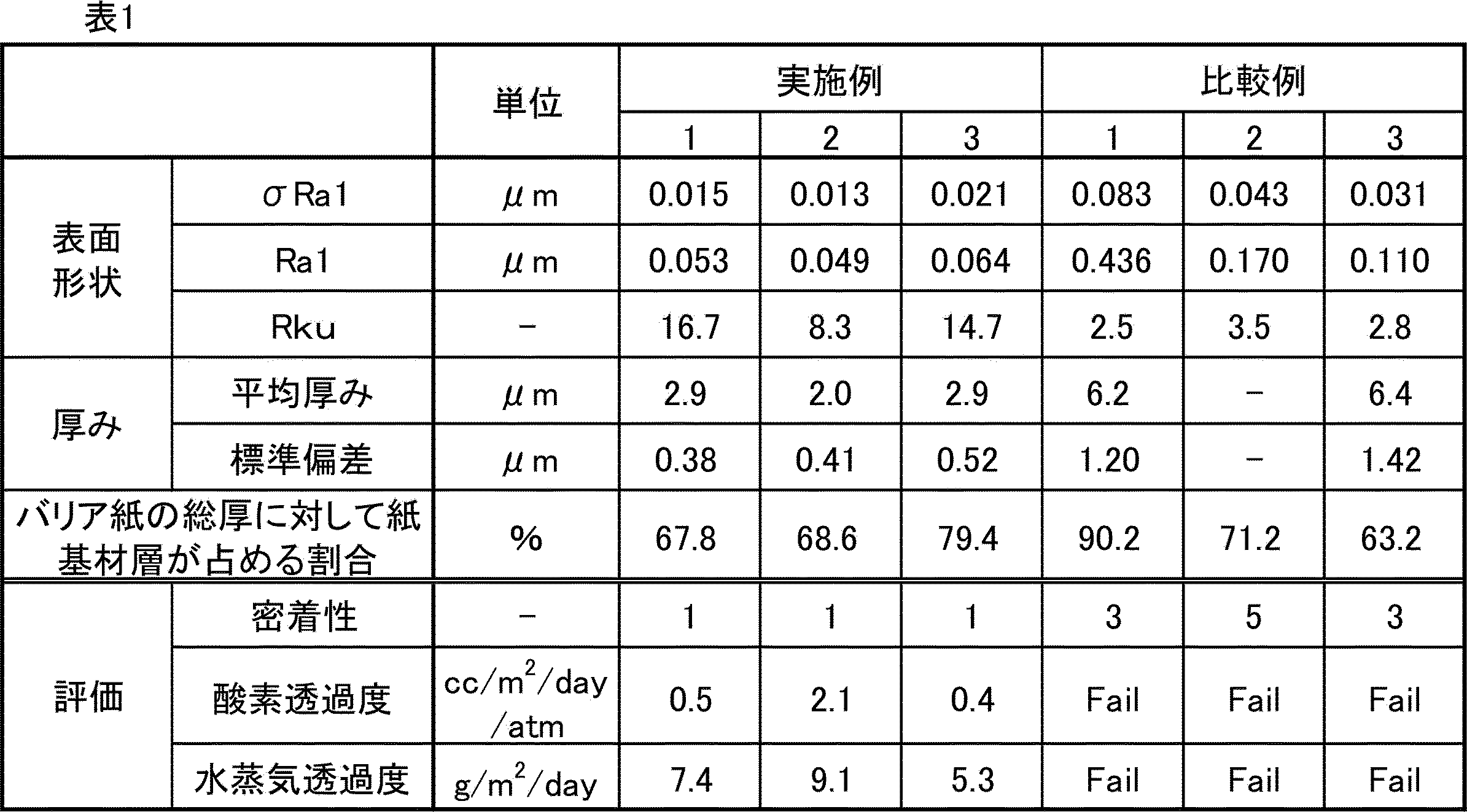
表1の結果から、実施例のバリア紙は、バリア性が良好であることが確認できる。
100:バリア紙
10:紙基材層
20:目止め層
30:接着剤層
40:無機蒸着層
50:剥離層
60:ヒートシール層
70:プライマー層
10:紙基材層
20:目止め層
30:接着剤層
40:無機蒸着層
50:剥離層
60:ヒートシール層
70:プライマー層
Claims (15)
- 紙基材層、接着剤層、無機蒸着層をこの順に有し、前記接着剤層と前記無機蒸着層とが接してなる、バリア紙。
- 前記無機蒸着層の前記紙基材層とは反対側の面の算術平均粗さをRa1、前記Ra1の標準偏差をσRa1と定義した際に、σRa1が0.030μm以下である、請求項1に記載のバリア紙。
- 前記無機蒸着層の前記紙基材層とは反対側の面の算術平均粗さをRa1と定義した際に、前記Ra1が0.100μm以下である、請求項1又は2に記載のバリア紙。
- 前記無機蒸着層の前記紙基材層とは反対側の面の粗さ曲線のクルトシスをRku1と定義した際に、Rku1が3.0超である、請求項1~3の何れかに記載のバリア紙。
- 前記紙基材層と前記接着剤層との間に目止め層を有する、請求項1~4の何れかに記載のバリア紙。
- 前記無機蒸着層の接着剤層とは反対側に、剥離層、保護層、ヒートシール層及びシーラント層から選ばれる1以上の層を有する、請求項1~5の何れかに記載のバリア紙。
- 前記紙基材層の接着剤層とは反対側に印刷層を有する、請求項1~6の何れかに記載のバリア紙。
- 前記接着剤層の厚みが1μm以上20μm以下である、請求項1~7の何れかに記載のバリア紙。
- 前記接着剤層の厚みの標準偏差が0.80μm以下である、請求項1~8の何れかに記載のバリア紙。
- 前記接着剤層の厚みの変動係数が0.17以下である、請求項1~9の何れかに記載のバリア紙。
- 前記バリア紙中の、前記紙基材層が占める厚み割合が60%以上100%未満である、請求項1~10の何れかに記載のバリア紙。
- 前記接着剤層と前記無機蒸着層との間の層間密着強度が、JIS K5600-5-6のクロスカット試験において、分類0、1及び2の何れかである、請求項1~11の何れかに記載のバリア紙。
- 請求項1~12の何れかに記載のバリア紙を含む容器。
- 請求項1~12の何れかに記載のバリア紙を含む蓋材。
- 下記の工程1~2を含む、バリア紙の製造方法。
工程1:離型性を有する支持体上に無機蒸着層を有する無機蒸着層供与体と、紙基材層とを、接着剤層を介して貼り合わせて、バリア紙中間体を作製する工程。但し、工程1において、前記無機蒸着層供与体は、前記離型性を有する支持体を基準として、前記無機蒸着層を有する側の面が前記紙基材層側を向くように配置する。
工程2:工程1で得たバリア紙中間体から前記離型性を有する支持体を剥離して、下記のバリア紙を得る工程。
(バリア紙)
紙基材層、接着剤層、無機蒸着層をこの順に有し、前記接着剤層と前記無機蒸着層とが接してなる、バリア紙。
Priority Applications (3)
| Application Number | Priority Date | Filing Date | Title |
|---|---|---|---|
| US17/781,695 US20230068867A1 (en) | 2019-12-06 | 2020-11-26 | Barrier paper, container and lid member containing said barrier paper, and method for producing barrier paper |
| EP20897567.2A EP4070949A4 (en) | 2019-12-06 | 2020-11-26 | Barrier paper, container and lid member containing said barrier paper, and method for producing barrier paper |
| PH1/2022/551666A PH12022551666A1 (en) | 2019-12-06 | 2020-11-26 | Barrier paper, container and lid member containing said barrier paper, and method for producing barrier paper |
Applications Claiming Priority (8)
| Application Number | Priority Date | Filing Date | Title |
|---|---|---|---|
| JP2019221463A JP7380159B2 (ja) | 2019-12-06 | 2019-12-06 | バリア紙 |
| JP2019221462A JP7451977B2 (ja) | 2019-12-06 | 2019-12-06 | バリア紙 |
| JP2019-221463 | 2019-12-06 | ||
| JP2019-221462 | 2019-12-06 | ||
| JP2020-183702 | 2020-11-02 | ||
| JP2020183702A JP7505373B2 (ja) | 2020-11-02 | 2020-11-02 | バリア紙、並びに、前記バリア紙を含む容器及び蓋材、並びに、バリア紙の製造方法 |
| JP2020-183695 | 2020-11-02 | ||
| JP2020183695A JP7505372B2 (ja) | 2020-11-02 | 2020-11-02 | バリア紙、並びに、前記バリア紙を含む容器及び蓋材、並びに、バリア紙の製造方法 |
Publications (1)
| Publication Number | Publication Date |
|---|---|
| WO2021111973A1 true WO2021111973A1 (ja) | 2021-06-10 |
Family
ID=76221587
Family Applications (1)
| Application Number | Title | Priority Date | Filing Date |
|---|---|---|---|
| PCT/JP2020/043996 Ceased WO2021111973A1 (ja) | 2019-12-06 | 2020-11-26 | バリア紙、並びに、前記バリア紙を含む容器及び蓋材、並びに、バリア紙の製造方法 |
Country Status (4)
| Country | Link |
|---|---|
| US (1) | US20230068867A1 (ja) |
| EP (1) | EP4070949A4 (ja) |
| PH (1) | PH12022551666A1 (ja) |
| WO (1) | WO2021111973A1 (ja) |
Cited By (7)
| Publication number | Priority date | Publication date | Assignee | Title |
|---|---|---|---|---|
| WO2023276601A1 (ja) * | 2021-06-30 | 2023-01-05 | サカタインクス株式会社 | ガスバリア性紙包材の製造方法、及び、ガスバリア性紙包材 |
| JP2023077763A (ja) * | 2021-11-25 | 2023-06-06 | 凸版印刷株式会社 | 蓋体用積層シート、蓋体、食品用包装容器及び包装食品 |
| WO2023136220A1 (ja) * | 2022-01-11 | 2023-07-20 | 凸版印刷株式会社 | ガスバリア積層体及び包装袋 |
| WO2023158393A1 (en) | 2022-02-16 | 2023-08-24 | Duran Doğan Basim Ve Ambalaj Sanayi̇ A.Ş. | Packaging material and production method thereof |
| EP4373669A1 (en) | 2021-07-20 | 2024-05-29 | Société des Produits Nestlé S.A. | A multi-layer flexible packaging material |
| JP2024110979A (ja) * | 2019-07-12 | 2024-08-16 | 王子ホールディングス株式会社 | 紙積層体 |
| WO2025033201A1 (ja) * | 2023-08-04 | 2025-02-13 | 共同印刷株式会社 | 蓋材及びその製造方法 |
Families Citing this family (3)
| Publication number | Priority date | Publication date | Assignee | Title |
|---|---|---|---|---|
| WO2021111973A1 (ja) * | 2019-12-06 | 2021-06-10 | 大日本印刷株式会社 | バリア紙、並びに、前記バリア紙を含む容器及び蓋材、並びに、バリア紙の製造方法 |
| WO2022154032A1 (ja) * | 2021-01-15 | 2022-07-21 | 王子ホールディングス株式会社 | 蒸着紙およびその製造方法 |
| KR20260015909A (ko) * | 2023-06-15 | 2026-02-03 | 쾰러 이노베이션 & 테크놀로지 게엠베하 | 친환경 포장재 |
Citations (14)
| Publication number | Priority date | Publication date | Assignee | Title |
|---|---|---|---|---|
| JPS5571725A (en) * | 1978-11-24 | 1980-05-30 | Dainippon Printing Co Ltd | Manufacturing of metallized paper |
| JPS576534U (ja) * | 1980-06-11 | 1982-01-13 | ||
| JPS57149133U (ja) * | 1981-03-14 | 1982-09-18 | ||
| JPS5985748A (ja) * | 1982-11-09 | 1984-05-17 | 株式会社カナエ | Ptp包装体用裏張りシ−トの製造法 |
| JPH1095462A (ja) * | 1996-09-18 | 1998-04-14 | Toppan Printing Co Ltd | 複合容器 |
| JPH11240535A (ja) * | 1997-12-04 | 1999-09-07 | Nihon Tetrapak Kk | 紙容器用セミマテリアル、紙容器用セミマテリアルの製造法、紙容器用包材及び紙容器 |
| JP2003291296A (ja) * | 2002-04-04 | 2003-10-14 | Ishida Co Ltd | 積層材料 |
| JP2004351739A (ja) * | 2003-05-29 | 2004-12-16 | Toppan Printing Co Ltd | 紙容器用積層材料 |
| JP2006058408A (ja) * | 2004-08-18 | 2006-03-02 | Dainippon Printing Co Ltd | アルミニウム蒸着ラベルおよびその製造方法 |
| JP2008062990A (ja) * | 2006-09-11 | 2008-03-21 | Toppan Printing Co Ltd | サセプター台紙 |
| JP2010264984A (ja) * | 2009-05-12 | 2010-11-25 | Toppan Printing Co Ltd | 紙製液体容器 |
| JP2012025439A (ja) * | 2010-07-23 | 2012-02-09 | Toppan Printing Co Ltd | ストローの突き刺し性を有する紙製タブテープ |
| JP2012086858A (ja) * | 2010-10-18 | 2012-05-10 | Toppan Printing Co Ltd | 液体用紙容器 |
| JP2019147606A (ja) * | 2018-02-28 | 2019-09-05 | 凸版印刷株式会社 | 液体用紙容器 |
Family Cites Families (17)
| Publication number | Priority date | Publication date | Assignee | Title |
|---|---|---|---|---|
| JPS59199899A (ja) * | 1983-04-22 | 1984-11-13 | 株式会社ロツテ | 板ガム内包装用金属蒸着紙およびその製造方法 |
| US6218004B1 (en) * | 1995-04-06 | 2001-04-17 | David G. Shaw | Acrylate polymer coated sheet materials and method of production thereof |
| CZ294822B6 (cs) * | 1995-04-12 | 2005-03-16 | Westvaco Corporation | Vrstvené víčko a způsob jeho výroby |
| FI102401B1 (fi) * | 1997-05-28 | 1998-11-30 | Raisio Chem Oy | Menetelmä transparentin ja läpäisevyyttä vähentävän pinnoitteen aikaansaamiseksi paperille tai kartongille sekä menetelmässä käytettävä päällystysaine |
| US6358576B1 (en) * | 1998-02-12 | 2002-03-19 | International Paper Company | Clay-filled polymer barrier materials for food packaging applications |
| JP2002166495A (ja) * | 2000-11-29 | 2002-06-11 | Toppan Printing Co Ltd | 外装材およびそれを用いたパップ剤用外装袋 |
| JP2005053495A (ja) * | 2003-08-04 | 2005-03-03 | Dainippon Printing Co Ltd | 紙容器 |
| US20050145138A1 (en) * | 2003-12-30 | 2005-07-07 | Council Of Scientific And Industrial Research | Oxygen barrier material for packaging |
| JP4806917B2 (ja) * | 2004-10-20 | 2011-11-02 | 大日本印刷株式会社 | 合成樹脂製容器 |
| JP2007168802A (ja) * | 2005-12-19 | 2007-07-05 | Dainippon Printing Co Ltd | 注出口付き紙容器 |
| JP5553686B2 (ja) * | 2010-06-01 | 2014-07-16 | ユニチカ株式会社 | アンカーコート剤、包装材料及びその製造方法 |
| WO2017143188A1 (en) * | 2016-02-18 | 2017-08-24 | Evergreen Packaging, Inc. | Gable top with spout closure |
| JP6672882B2 (ja) * | 2016-02-24 | 2020-03-25 | 大日本印刷株式会社 | 印刷体 |
| JP6797357B2 (ja) * | 2016-06-24 | 2020-12-09 | Dic株式会社 | 積層体、及び積層体を用いた包装材 |
| JP6903879B2 (ja) * | 2016-07-29 | 2021-07-14 | 大日本印刷株式会社 | 酸素バリア性を有する積層体および該積層体からなる包装材料 |
| US11225355B2 (en) * | 2017-11-08 | 2022-01-18 | Sonoco Development, Inc. | Membrane lid with integrated peelable portion |
| WO2021111973A1 (ja) * | 2019-12-06 | 2021-06-10 | 大日本印刷株式会社 | バリア紙、並びに、前記バリア紙を含む容器及び蓋材、並びに、バリア紙の製造方法 |
-
2020
- 2020-11-26 WO PCT/JP2020/043996 patent/WO2021111973A1/ja not_active Ceased
- 2020-11-26 US US17/781,695 patent/US20230068867A1/en active Pending
- 2020-11-26 PH PH1/2022/551666A patent/PH12022551666A1/en unknown
- 2020-11-26 EP EP20897567.2A patent/EP4070949A4/en active Pending
Patent Citations (14)
| Publication number | Priority date | Publication date | Assignee | Title |
|---|---|---|---|---|
| JPS5571725A (en) * | 1978-11-24 | 1980-05-30 | Dainippon Printing Co Ltd | Manufacturing of metallized paper |
| JPS576534U (ja) * | 1980-06-11 | 1982-01-13 | ||
| JPS57149133U (ja) * | 1981-03-14 | 1982-09-18 | ||
| JPS5985748A (ja) * | 1982-11-09 | 1984-05-17 | 株式会社カナエ | Ptp包装体用裏張りシ−トの製造法 |
| JPH1095462A (ja) * | 1996-09-18 | 1998-04-14 | Toppan Printing Co Ltd | 複合容器 |
| JPH11240535A (ja) * | 1997-12-04 | 1999-09-07 | Nihon Tetrapak Kk | 紙容器用セミマテリアル、紙容器用セミマテリアルの製造法、紙容器用包材及び紙容器 |
| JP2003291296A (ja) * | 2002-04-04 | 2003-10-14 | Ishida Co Ltd | 積層材料 |
| JP2004351739A (ja) * | 2003-05-29 | 2004-12-16 | Toppan Printing Co Ltd | 紙容器用積層材料 |
| JP2006058408A (ja) * | 2004-08-18 | 2006-03-02 | Dainippon Printing Co Ltd | アルミニウム蒸着ラベルおよびその製造方法 |
| JP2008062990A (ja) * | 2006-09-11 | 2008-03-21 | Toppan Printing Co Ltd | サセプター台紙 |
| JP2010264984A (ja) * | 2009-05-12 | 2010-11-25 | Toppan Printing Co Ltd | 紙製液体容器 |
| JP2012025439A (ja) * | 2010-07-23 | 2012-02-09 | Toppan Printing Co Ltd | ストローの突き刺し性を有する紙製タブテープ |
| JP2012086858A (ja) * | 2010-10-18 | 2012-05-10 | Toppan Printing Co Ltd | 液体用紙容器 |
| JP2019147606A (ja) * | 2018-02-28 | 2019-09-05 | 凸版印刷株式会社 | 液体用紙容器 |
Non-Patent Citations (1)
| Title |
|---|
| See also references of EP4070949A4 * |
Cited By (10)
| Publication number | Priority date | Publication date | Assignee | Title |
|---|---|---|---|---|
| JP2024110979A (ja) * | 2019-07-12 | 2024-08-16 | 王子ホールディングス株式会社 | 紙積層体 |
| JP7772134B2 (ja) | 2019-07-12 | 2025-11-18 | 王子ホールディングス株式会社 | 紙積層体 |
| WO2023276601A1 (ja) * | 2021-06-30 | 2023-01-05 | サカタインクス株式会社 | ガスバリア性紙包材の製造方法、及び、ガスバリア性紙包材 |
| JP2023006393A (ja) * | 2021-06-30 | 2023-01-18 | サカタインクス株式会社 | ガスバリア性紙包材の製造方法、及び、ガスバリア性紙包材 |
| EP4373669A1 (en) | 2021-07-20 | 2024-05-29 | Société des Produits Nestlé S.A. | A multi-layer flexible packaging material |
| JP2023077763A (ja) * | 2021-11-25 | 2023-06-06 | 凸版印刷株式会社 | 蓋体用積層シート、蓋体、食品用包装容器及び包装食品 |
| WO2023136220A1 (ja) * | 2022-01-11 | 2023-07-20 | 凸版印刷株式会社 | ガスバリア積層体及び包装袋 |
| WO2023158393A1 (en) | 2022-02-16 | 2023-08-24 | Duran Doğan Basim Ve Ambalaj Sanayi̇ A.Ş. | Packaging material and production method thereof |
| JP2025506214A (ja) * | 2022-02-16 | 2025-03-07 | デュラン ドアン バシム ヴェ アンバラジ サナイ エー.エス. | 包装材料及びその製造方法 |
| WO2025033201A1 (ja) * | 2023-08-04 | 2025-02-13 | 共同印刷株式会社 | 蓋材及びその製造方法 |
Also Published As
| Publication number | Publication date |
|---|---|
| US20230068867A1 (en) | 2023-03-02 |
| EP4070949A4 (en) | 2023-12-13 |
| EP4070949A1 (en) | 2022-10-12 |
| PH12022551666A1 (en) | 2023-12-11 |
Similar Documents
| Publication | Publication Date | Title |
|---|---|---|
| WO2021111973A1 (ja) | バリア紙、並びに、前記バリア紙を含む容器及び蓋材、並びに、バリア紙の製造方法 | |
| JP7377711B2 (ja) | コーティングされたフィルムおよびそれから形成される物品 | |
| JP7627402B2 (ja) | 転写フィルム | |
| US20240416632A1 (en) | Oxygen-absorbing coated multilayer body | |
| JP7380159B2 (ja) | バリア紙 | |
| JP2008201463A (ja) | シュリンクラベルおよびラベル付き容器 | |
| RU2764989C2 (ru) | Однопорционная упаковка | |
| JP7451977B2 (ja) | バリア紙 | |
| JP6316212B2 (ja) | 積層フィルム及び包装材 | |
| JP7622365B2 (ja) | 植物由来原料を含有する酸素吸収性積層体 | |
| JP6375805B2 (ja) | 積層フィルム及び包装材 | |
| JP7574475B2 (ja) | 包装材料 | |
| JP7505372B2 (ja) | バリア紙、並びに、前記バリア紙を含む容器及び蓋材、並びに、バリア紙の製造方法 | |
| JP7505373B2 (ja) | バリア紙、並びに、前記バリア紙を含む容器及び蓋材、並びに、バリア紙の製造方法 | |
| JP7643647B1 (ja) | 防曇性多層フィルム、これを用いる積層体、及び包装材 | |
| JP2025028241A (ja) | 積層フィルム | |
| WO2023153521A1 (ja) | 積層フィルム及び包装袋 | |
| JP7819796B2 (ja) | 酸素吸収性積層体 | |
| WO2025263326A1 (ja) | 防曇性多層フィルム、これを用いる積層体、及び包装材 | |
| JP2004058336A (ja) | レトルト用包材およびそれを使用したレトルト処理包装製品 | |
| WO2025070687A1 (ja) | ラミネート積層体 | |
| JP7443834B2 (ja) | パウチ | |
| JP2024043721A (ja) | 積層体、包装体、及びヒートシール組成物 | |
| HK40100085A (zh) | 转印膜和阻隔性层积体 | |
| JP2023173714A (ja) | 蓋体用積層シート、蓋体、食品用包装容器および包装食品 |
Legal Events
| Date | Code | Title | Description |
|---|---|---|---|
| 121 | Ep: the epo has been informed by wipo that ep was designated in this application |
Ref document number: 20897567 Country of ref document: EP Kind code of ref document: A1 |
|
| NENP | Non-entry into the national phase |
Ref country code: DE |
|
| ENP | Entry into the national phase |
Ref document number: 2020897567 Country of ref document: EP Effective date: 20220706 |