WO2021117868A1 - ロボットシステム及びワークの3次元モデルの形成方法 - Google Patents
ロボットシステム及びワークの3次元モデルの形成方法 Download PDFInfo
- Publication number
- WO2021117868A1 WO2021117868A1 PCT/JP2020/046282 JP2020046282W WO2021117868A1 WO 2021117868 A1 WO2021117868 A1 WO 2021117868A1 JP 2020046282 W JP2020046282 W JP 2020046282W WO 2021117868 A1 WO2021117868 A1 WO 2021117868A1
- Authority
- WO
- WIPO (PCT)
- Prior art keywords
- work
- robot
- information
- control device
- image information
- Prior art date
- Legal status (The legal status is an assumption and is not a legal conclusion. Google has not performed a legal analysis and makes no representation as to the accuracy of the status listed.)
- Ceased
Links
Images





Classifications
-
- B—PERFORMING OPERATIONS; TRANSPORTING
- B25—HAND TOOLS; PORTABLE POWER-DRIVEN TOOLS; MANIPULATORS
- B25J—MANIPULATORS; CHAMBERS PROVIDED WITH MANIPULATION DEVICES
- B25J9/00—Program-controlled manipulators
- B25J9/16—Program controls
-
- B—PERFORMING OPERATIONS; TRANSPORTING
- B25—HAND TOOLS; PORTABLE POWER-DRIVEN TOOLS; MANIPULATORS
- B25J—MANIPULATORS; CHAMBERS PROVIDED WITH MANIPULATION DEVICES
- B25J9/00—Program-controlled manipulators
- B25J9/16—Program controls
- B25J9/1656—Program controls characterised by programming, planning systems for manipulators
- B25J9/1671—Program controls characterised by programming, planning systems for manipulators characterised by simulation, either to verify existing program or to create and verify new program, CAD/CAM oriented, graphic oriented programming systems
-
- B—PERFORMING OPERATIONS; TRANSPORTING
- B25—HAND TOOLS; PORTABLE POWER-DRIVEN TOOLS; MANIPULATORS
- B25J—MANIPULATORS; CHAMBERS PROVIDED WITH MANIPULATION DEVICES
- B25J13/00—Controls for manipulators
- B25J13/06—Control stands, e.g. consoles, switchboards
- B25J13/065—Control stands, e.g. consoles, switchboards comprising joy-sticks
-
- B—PERFORMING OPERATIONS; TRANSPORTING
- B25—HAND TOOLS; PORTABLE POWER-DRIVEN TOOLS; MANIPULATORS
- B25J—MANIPULATORS; CHAMBERS PROVIDED WITH MANIPULATION DEVICES
- B25J11/00—Manipulators not otherwise provided for
-
- B—PERFORMING OPERATIONS; TRANSPORTING
- B25—HAND TOOLS; PORTABLE POWER-DRIVEN TOOLS; MANIPULATORS
- B25J—MANIPULATORS; CHAMBERS PROVIDED WITH MANIPULATION DEVICES
- B25J13/00—Controls for manipulators
-
- B—PERFORMING OPERATIONS; TRANSPORTING
- B25—HAND TOOLS; PORTABLE POWER-DRIVEN TOOLS; MANIPULATORS
- B25J—MANIPULATORS; CHAMBERS PROVIDED WITH MANIPULATION DEVICES
- B25J13/00—Controls for manipulators
- B25J13/08—Controls for manipulators by means of sensing devices, e.g. viewing or touching devices
-
- B—PERFORMING OPERATIONS; TRANSPORTING
- B25—HAND TOOLS; PORTABLE POWER-DRIVEN TOOLS; MANIPULATORS
- B25J—MANIPULATORS; CHAMBERS PROVIDED WITH MANIPULATION DEVICES
- B25J13/00—Controls for manipulators
- B25J13/08—Controls for manipulators by means of sensing devices, e.g. viewing or touching devices
- B25J13/088—Controls for manipulators by means of sensing devices, e.g. viewing or touching devices with position, velocity or acceleration sensors
- B25J13/089—Determining the position of the robot with reference to its environment
-
- B—PERFORMING OPERATIONS; TRANSPORTING
- B25—HAND TOOLS; PORTABLE POWER-DRIVEN TOOLS; MANIPULATORS
- B25J—MANIPULATORS; CHAMBERS PROVIDED WITH MANIPULATION DEVICES
- B25J9/00—Program-controlled manipulators
- B25J9/16—Program controls
- B25J9/1602—Program controls characterised by the control system, structure, architecture
- B25J9/1605—Simulation of manipulator lay-out, design, modelling of manipulator
-
- B—PERFORMING OPERATIONS; TRANSPORTING
- B25—HAND TOOLS; PORTABLE POWER-DRIVEN TOOLS; MANIPULATORS
- B25J—MANIPULATORS; CHAMBERS PROVIDED WITH MANIPULATION DEVICES
- B25J9/00—Program-controlled manipulators
- B25J9/16—Program controls
- B25J9/1679—Program controls characterised by the tasks executed
- B25J9/1689—Teleoperation
-
- B—PERFORMING OPERATIONS; TRANSPORTING
- B25—HAND TOOLS; PORTABLE POWER-DRIVEN TOOLS; MANIPULATORS
- B25J—MANIPULATORS; CHAMBERS PROVIDED WITH MANIPULATION DEVICES
- B25J9/00—Program-controlled manipulators
- B25J9/16—Program controls
- B25J9/1694—Program controls characterised by use of sensors other than normal servo-feedback from position, speed or acceleration sensors, perception control, multi-sensor controlled systems, sensor fusion
-
- B—PERFORMING OPERATIONS; TRANSPORTING
- B25—HAND TOOLS; PORTABLE POWER-DRIVEN TOOLS; MANIPULATORS
- B25J—MANIPULATORS; CHAMBERS PROVIDED WITH MANIPULATION DEVICES
- B25J9/00—Program-controlled manipulators
- B25J9/16—Program controls
- B25J9/1694—Program controls characterised by use of sensors other than normal servo-feedback from position, speed or acceleration sensors, perception control, multi-sensor controlled systems, sensor fusion
- B25J9/1697—Vision controlled systems
-
- G—PHYSICS
- G05—CONTROLLING; REGULATING
- G05B—CONTROL OR REGULATING SYSTEMS IN GENERAL; FUNCTIONAL ELEMENTS OF SUCH SYSTEMS; MONITORING OR TESTING ARRANGEMENTS FOR SUCH SYSTEMS OR ELEMENTS
- G05B2219/00—Program-control systems
- G05B2219/30—Nc systems
- G05B2219/40—Robotics, robotics mapping to robotics vision
- G05B2219/40131—Virtual reality control, programming of manipulator
-
- G—PHYSICS
- G05—CONTROLLING; REGULATING
- G05B—CONTROL OR REGULATING SYSTEMS IN GENERAL; FUNCTIONAL ELEMENTS OF SUCH SYSTEMS; MONITORING OR TESTING ARRANGEMENTS FOR SUCH SYSTEMS OR ELEMENTS
- G05B2219/00—Program-control systems
- G05B2219/30—Nc systems
- G05B2219/40—Robotics, robotics mapping to robotics vision
- G05B2219/40195—Tele-operation, computer assisted manual operation
Definitions
- This disclosure relates to a method of forming a three-dimensional model of a robot system and a work.
- a display system for displaying a three-dimensional image representing a robot work cell on various mobile terminals is known (see, for example, Patent Document 1).
- a display that generates robot work cell data including a three-dimensional robot model and a model of another structure of the work cell and displays a three-dimensional rendering of the generated three-dimensional robot model or the like. have.
- Patent Document 1 when a user (operator) operates a robot displayed on a display by using an operating means, before the robot executes an operation. , Showing a collision object (eg, a safety wall) in the display. Then, when the physical robot collides with the colliding object by the user's operation, the collision is displayed on the display.
- a collision object eg, a safety wall
- the programmer needs to create three-dimensional data such as a three-dimensional robot model and an animated three-dimensional robot model. Therefore, as the number of types of work to be worked on by the robot increases, the number of data to be created becomes enormous, and the data creation cost increases. In particular, when the amount of work is small, the ratio of the data creation cost to the production cost becomes large.
- the display system disclosed in Patent Document 1 still has room for improvement from the viewpoint of improving production efficiency.
- the present disclosure solves the above problems, and an object of the present disclosure is to provide a method for forming a three-dimensional model of a robot system and a work, which can improve production efficiency as compared with a conventional display system.
- the robot system is installed in a work area, and is arranged in a robot controlled by a second control device, a 3D camera operated by an operator, and an operation area which is a space different from the work area.
- a sensor that wirelessly detects position information and attitude information of the 3D camera, a display device, and a first control device are provided, and the first control device obtains image information of a work taken by the 3D camera.
- the position information and the attitude information when the work is photographed by the 3D camera are acquired from the sensor, the acquired image information is displayed on the display device, and the acquired image information and the acquired image information are displayed.
- Based on the acquired position information and the attitude information a three-dimensional model of the work is formed, and the formed three-dimensional model is displayed on the display device, and the formed three-dimensional model of the formed
- the first data, which is data, is output to the second control device.
- the method of forming a three-dimensional model of the work according to the present disclosure is the method of forming the work in the operation area, which is a space different from the work area where the robot is installed, when the work is photographed by the 3D camera.
- the position information and the posture information of the above are detected, the image information of the photographed work is acquired, the detected position information and the attitude information are acquired, and the acquired image information is displayed on the display device.
- a three-dimensional model of the work is formed based on the acquired image information, the acquired position information, and the attitude information.
- the production efficiency can be improved as compared with the conventional display system.
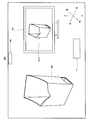
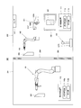
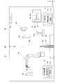
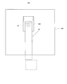
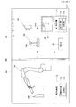
- FIG. 1 is a schematic diagram showing a schematic configuration of a robot system according to the first embodiment.
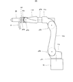
- FIG. 2 is a schematic diagram showing a schematic configuration of a robot in the robot system shown in FIG.
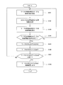
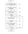
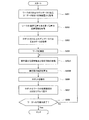
- FIG. 3 is a flowchart showing an example of the operation of the robot system according to the first embodiment.
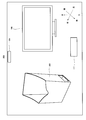
- FIG. 4 is a schematic view showing a state in the operation area when the robot system is operating according to the flowchart shown in FIG.
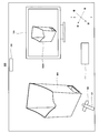
- FIG. 5 is a schematic view showing a state in the operation area when the robot system is operating according to the flowchart shown in FIG.
- FIG. 6 is a schematic view showing a state in the operation area when the robot system is operating according to the flowchart shown in FIG.
- FIG. 1 is a schematic diagram showing a schematic configuration of a robot system according to the first embodiment.
- FIG. 2 is a schematic diagram showing a schematic configuration of a robot in the robot system shown in FIG.
- FIG. 3 is a flowchart showing an example of the operation of the robot system
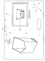
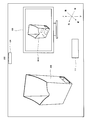
- FIG. 7 is a schematic view showing a state in the operation area when the robot system is operating according to the flowchart shown in FIG.
- FIG. 8 is a schematic view showing a state in the operation area when the robot system is operating according to the flowchart shown in FIG.
- FIG. 9 is a schematic view showing a state in the operation area when the robot system is operating according to the flowchart shown in FIG.
- FIG. 10 is a schematic diagram showing a schematic configuration of the robot system of the modified example 1 in the first embodiment.
- FIG. 11 is a schematic diagram showing a schematic configuration of the robot system of the modified example 2 in the first embodiment.
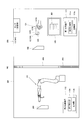
- FIG. 12 is a schematic diagram showing a schematic configuration of the robot system according to the second embodiment.
- FIG. 13 is a schematic view showing a state in which the work area is viewed from a window in the robot system shown in FIG.
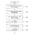
- FIG. 14 is a flowchart showing an example of the operation of the robot system according to the second embodiment.
- FIG. 15 is a schematic diagram showing a schematic configuration of the robot system of the first modification in the second embodiment.
- FIG. 16 is a flowchart showing an example of the operation of the robot system of the modified example 1 in the second embodiment.
- FIG. 17 is a schematic diagram showing a schematic configuration of the robot system of the modified example 2 in the second embodiment.
- FIG. 18 is a schematic diagram showing a schematic configuration of the robot system of the modified example 2 in the second embodiment.
- FIG. 19 is a schematic diagram showing a schematic configuration of the robot system according to the third embodiment.
- FIG. 20A is a flowchart showing an example of the operation of the robot system according to the third embodiment.
- FIG. 20B is a flowchart showing an example of the operation of the robot system according to the
- FIG. 1 is a schematic diagram showing a schematic configuration of a robot system according to the first embodiment.
- the robot system 100 includes a robot 101, a first controller 121, a 3D camera 103, a sensor 104, a display device 105, a first control device 111, and a second control device 112.
- the robot 101 and the second control device 112 are installed in the work area 201, and the sensor 104, the display device 105, and the first control device 111 are arranged in the operation area 202.
- the first actuator 121 is operated by being gripped (held) by the operator in the operation area 202.
- a 3D camera 103 is arranged at the tip of the first actuator 121.
- the 3D camera 103 is provided at the tip of the first actuator 121, but the 3D camera 103 may not be provided at the first actuator 121 in 3D.
- the camera 103 and the first actuator 121 may be configured as separate bodies.
- the work area 201 is a space in which the robot 101 is installed, and includes at least a space within the operating range of the robot 101. Further, the operation area 202 is a space separated from the work area 201 (a space different from the work area 201). The work area 201 and the operation area 202 may be partitioned by the wall member 203.
- the wall member 203 is provided with a window 204 so that the operator can visually recognize the robot 101 arranged in the work area 201.
- the work area 201 may be an explosion-proof area provided with explosion-proof specifications, and the operation area 202 may be a non-explosion-proof area not provided with explosion-proof specifications.
- the sensor 104 wirelessly detects the position information and the attitude information of the 3D camera 103 (for example, the lens) and outputs them to the first control device 111. Further, the sensor 104 wirelessly detects the position information and the posture information of the tip portion of the first actuator 121 and outputs the position information and the attitude information to the second control device 112. The sensor 104 may output to the first control device 111 and / or the second control device 112 wirelessly or by wire.
- the sensor 104 may be, for example, an infrared sensor or a camera. When the sensor 104 is a camera, the sensor 104 may not be arranged in the operation area 202.
- the camera may be a camera installed on a mobile terminal or a head-mounted display carried by the operator.
- the sensor 104 that detects the position information of the 3D camera 103 and the sensor 104 that detects the position information of the tip of the first actuator 121 may be configured by the same sensor, and may be different sensors. It may be configured.
- the operator grips the grip portion 121A and operates the robot 101. Specifically, the robot 101 operates so as to follow the trajectory of the tip of the main body 121E in the first actuator 121 that is being gripped, so that the operator can operate the first actuator within the operation area 202. With 121, the robot 101 can be operated intuitively.
- the grip portion 121A may be provided with a device that transmits force sense information or voice information detected by a force sense sensor provided in the end effector 20 of the robot 101, which will be described later, to the operator.
- the device include a vibration motor, a speaker, a mechanism for expanding and contracting a housing constituting a grip portion, and the like.
- the first actuator 121 may be provided with a switch 121B for spraying or injecting particles, liquid, or gas onto the work 300, or starting / stopping cutting or polishing of the work 300.
- the first actuator 121 may be configured to be portable and portable by the operator. Further, the main body 121E of the first actuator 121 may be formed in the same shape as the end effector 20 of the robot 101. Further, as the first actuator 121, a known actuator such as a joystick, a keyboard, a numeric keypad, or a teach pendant may be used.
- the 3D camera 103 outputs the image information captured in the operation area 202 to the first control device 111.
- the "image information” referred to here includes at least one of still image information, moving image information, and video information. The same applies to the term “image information” in the following description.
- the sensor 104 wirelessly detects the position information and the posture information of the 3D camera 103 and outputs them to the first control device 111.
- the display device 105 displays the image information of the work 300 and the like output from the first control device 111 and the three-dimensional model of the robot 101 and the like and the work 300 and the like taken by the 3D camera 103.
- the display device 105 may be configured by, for example, a stationary display that is used by being stationary on a desk, floor, or the like. Further, the display device 105 may be composed of a head-mounted display or glasses worn and used by the operator.
- the end effector 20 of the robot 101 may have a structure capable of spraying or injecting particles, liquid, or gas onto the work 300, a structure capable of cutting or polishing the work 300, or the work 300.
- the structure may be weldable, or the work 300 may be washable.
- FIG. 2 is a schematic diagram showing a schematic configuration of a robot in the robot system shown in FIG.
- the robot 101 connects a plurality of links (here, the first link 11a, the second link 11b, the third link 11c, the fourth link 11d, the fifth link 11e, and the sixth link 11f).
- the body a plurality of joints (here, 1st joint JT1, 2nd joint JT2, 3rd joint JT3, 4th joint JT4, 5th joint JT5 and 6th joint JT6), and a base 15 supporting them.
- a vertical articulated robot arm In the first embodiment, a vertical articulated robot is adopted as the robot 101, but the robot 101 is not limited to this, and a horizontal articulated robot may be adopted.
- the base 15 and the base end portion of the first link 11a are rotatably connected around an axis extending in the vertical direction.
- the tip end portion of the first link 11a and the base end portion of the second link 11b are rotatably connected around an axis extending in the horizontal direction.
- the tip end portion of the second link 11b and the base end portion of the third link 11c are rotatably connected around an axis extending in the horizontal direction.
- the tip end portion of the third link 11c and the base end portion of the fourth link 11d are rotatably connected around an axis extending in the longitudinal direction of the fourth link 11d.
- the tip end portion of the fourth link 11d and the base end portion of the fifth link 11e are rotatably connected around an axis orthogonal to the longitudinal direction of the fourth link 11d.
- the tip end portion of the fifth link 11e and the base end portion of the sixth link 11f are rotatably connected to each other.
- a mechanical interface is provided at the tip of the 6th link 11f.
- An end effector 20 corresponding to the work content is detachably attached to this mechanical interface.
- the end effector 20 sprays or sprays a liquid (for example, paint or the like) on the work 300. Further, a pipe 21 for supplying a liquid to the end effector 20 is connected to the end effector 20.
- a liquid for example, paint or the like
- first joint JT1, the second joint JT2, the third joint JT3, the fourth joint JT4, the fifth joint JT5, and the sixth joint JT6 are each relatively rotated with two members connected to each joint.
- a drive motor is provided as an example of an actuator (not shown).
- the drive motor may be, for example, a servomotor that is servo-controlled by the second control device 112.
- the first joint JT1, the second joint JT2, the third joint JT3, the fourth joint JT4, the fifth joint JT5, and the sixth joint JT6 have a rotation sensor for detecting the rotation position of the drive motor and a drive motor, respectively.
- a current sensor that detects the current that controls the rotation of the joint is provided (not shown).
- the rotation sensor may be, for example, an encoder.
- the first control device 111 includes an arithmetic processor 111a such as a microprocessor and a CPU, and a storage device 111b such as a ROM and a RAM. Information such as a basic program and various fixed data is stored in the storage device 111b.
- the arithmetic processor 111a reads and executes software such as a basic program stored in the storage 111b.
- the arithmetic processor 111a is based on the image information input from the 3D camera 103 and the position information and the posture information when the 3D camera 103 input from the sensor 104 captures the work 300, so that the work 300 is three-dimensional.
- Form a model (3D computer graphics or 3D CAD data).
- the storage device 111b stores a three-dimensional model of the work 300 formed by the arithmetic processing unit 111a.
- the arithmetic processor 111a outputs the three-dimensional model of the formed work 300 to the display device 105.
- the display device 105 displays the three-dimensional model of the work 300 input from the arithmetic processor 111a as the 3D work 301 (see FIG. 6 and the like).
- the second control device 112 like the first control device 111, includes an arithmetic processor 112a such as a microprocessor and a CPU, and a storage device 112b such as a ROM and a RAM. Information such as a basic program and various fixed data is stored in the storage device 112b.
- the arithmetic processor 112a executes various operations of the robot 101 by reading and executing software such as a basic program stored in the storage device 112b.
- the first control device 111 and / or the second control device 112 may be composed of a single control device for centralized control, or may be composed of a plurality of control devices for distributed control in cooperation with each other. May be good. Further, the first control device 111 and / or the second control device 112 may be composed of a microcomputer, an MPU, a PLC (Programmable Logic Controller), a logic circuit, or the like.
- a microcomputer an MPU, a PLC (Programmable Logic Controller), a logic circuit, or the like.
- the present invention is not limited to this.
- the first control device 111 may also have the function of the second control device 112, that is, the robot system 100 may adopt a form including only the first control device 111.
- the second control device 112 may also have the function of the first control device 111, that is, the robot system 100 may adopt a form including only the second control device 112.
- FIG. 3 is a flowchart showing an example of the operation of the robot system according to the first embodiment (a method of forming a three-dimensional model of a work).
- 4 to 9 are schematic views showing a state in the operation area when the robot system is operating according to the flowchart shown in FIG.
- the front-back direction, the left-right direction, and the up-down direction of the work are represented as the front-back direction, the left-right direction, and the up-down direction in the figure.
- FIG. 4 it is assumed that a box-shaped work 300 having an open upper portion is arranged in the operation area 202. Then, as shown in FIG. 5, the operator (operator) grips the first actuator 121 on which the 3D camera 103 is installed in order to create a three-dimensional model of the work 300, and the work 300. It is assumed that the work 300 is photographed from the front of the work 300.
- the operator may acquire (photograph) the image information of one work 300 by the 3D camera 103, or may acquire (photograph) the image information of a plurality of works 300 discontinuously.
- the video information of the work 300 may be acquired (photographed).
- the operator may use the 3D camera 103 to take a picture of the work 300 from a direction other than the front of the work 300.
- the first control device 111 acquires the image information of the work 300 taken by the 3D camera 103 from the 3D camera 103 (step S101). Next, the first control device 111 acquires the position information and the posture information of the 3D camera 103 when the image information acquired in step S101 is taken from the sensor 104 (step S102).
- the first control device 111 displays the image information of the work 300 acquired in step S101 as the work image 302A on the display device 105 (step S103; see FIG. 5).
- the first control device 111 determines whether or not the acquisition end instruction command for the image information of the work 300 (shooting end information of the work 300) has been input from an input device or the like (not shown) from the operator (step). S104).
- the first control device 111 determines that the shooting end information of the work 300 has been input from the input device or the like (Yes in step S104), the image information of the work 300 acquired in step S101 and the image information of the work 300 acquired in step S102 are acquired.
- a three-dimensional model (3D computer graphics or 3D CAD) of the work 300 is formed based on the position information and the attitude information of the 3D camera 103 (step S105).
- the first control device 111 displays the three-dimensional model of the work 300 formed in step S105 as the 3D work 301A on the display device 105 (step S106; see FIG. 6).
- the first control device 111 determines whether or not the operator has input the three-dimensional model formation end instruction (three-dimensional model formation end information) of the work 300 from an input device (not shown) or the like (step). S107).
- step S107 When the first control device 111 determines that the three-dimensional model formation end information has not been input from the input device or the like (No in step S107), the first control device 111 returns to the process of step S101. On the other hand, when the first control device 111 determines that the three-dimensional model formation end information has been input from the input device or the like (Yes in step S107), the first control device 111 proceeds to the process of step S108.
- step S108 the first control device 111 outputs the three-dimensional model of the work 300 formed in step S105 to the second control device 112, and ends this program.
- the second control device 112 can control the operation of the robot 101 based on the three-dimensional model data of the work 300.
- step S104 for example, after displaying the work image 302A on the display device 105, the first control device 111 further photographs the work 300, and the image information of the work 300 captured from the 3D camera 103 is obtained. If it is input, it may be determined from the input device or the like that the shooting end information of the work 300 has not been input.
- step S104 When the first control device 111 determines that the shooting end information of the work 300 has not been input (No in step S104), the process returns to the process of step S101.
- the image information of the captured work 300 is input to the first control device 111 (step S101). ).
- the first control device 111 acquires the position information and the attitude information of the 3D camera 103 when the image information acquired in the second step S101 is taken from the sensor 104 (step S102).
- the first control device 111 displays the image information of the work 300 acquired in the second step S101 as the work image 302B on the display device 105 (step S103; see FIG. 7). As a result, it can be seen that a rectangular through hole is formed in the lower part of the rear surface of the work 300.
- the first control device 111 determines whether or not the acquisition end instruction command for the image information of the work 300 has been input from an input device or the like (not shown) (step S104).
- the image information of the photographed work 300 is input to the first control device 111 (step). S101).
- the first control device 111 acquires the position information and the attitude information of the 3D camera 103 when the image information acquired in the third step S101 is taken from the sensor 104 (step S102).
- the first control device 111 displays the image information of the work 300 acquired in the third step S101 as the work image 302C on the display device 105 (step S103; see FIG. 8). As a result, it can be seen that a rectangular through hole is formed on the lower surface of the work 300. Further, the operator can see that the shooting of all the parts of the work 300 has been completed. Therefore, the operator causes the first control device 111 to output the shooting end information of the work 300 from the input device or the like.
- the first control device 111 determines that the shooting end information of the work 300 has been input from the input device or the like (Yes in step S104), and acquires the image information of the work 300 acquired in step S101 and the image information of the work 300 in step S102.
- a three-dimensional model of the work 300 is formed based on the position information and the attitude information of the 3D camera 103 (step S105).
- the first control device 111 forms a three-dimensional model of the work 300 based on, for example, the image information of the work 300 acquired each time and the position information and the attitude information of the 3D camera 103 acquired each time. You may.
- the first control device 111 forms a three-dimensional model of the work 300 based on the image information of the work 300 and the position information and the posture information of the 3D camera 103 at each time, and the formed work 300 of the work 300.
- the 3D model of the work 300 may be reformed based on the 3D model group.
- the first control device 111 creates a three-dimensional model of the work 300 based on, for example, the image information of the work 300 acquired in the Ath time (for example, the first time) and the position information and the posture information of the 3D camera 103.
- the three-dimensional model of the work 300 formed in the process of forming (step S105) and the process of forming the three-dimensional model (step S105), and the B-th time (B ⁇ A; for example, the second time and the third time) were acquired.
- the process of reforming the three-dimensional model of the work 300 may be executed based on the image information of the work 300 and the position information and the posture information of the 3D camera 103.
- the first control device 111 of the work 300 is based on, for example, the image information of the work 300 acquired in the Ath time (for example, the first time and the second time) and the position information and the posture information of the 3D camera 103. Acquired in the Bth time (B ⁇ A; for example, the third time) of the process of forming the 3D model (step S105) and the 3D model of the work 300 formed in the process of forming the 3D model (step S105). Based on the image information of the work 300, the process of reforming the three-dimensional model of the work 300 may be executed.
- the first control device 111 is a three-dimensional model of the work 300 based on, for example, the image information of the work 300 acquired at the Cth time (for example, the first time) and the position information and the posture information of the 3D camera 103.
- Work based on the process of forming (step S105), the image information of the work 300 acquired in the Dth time (D ⁇ C; for example, the second time and the third time), and the position information and the attitude information of the 3D camera 103.
- the process of forming the 3D model of the 300 step S105), the image information of the work 300 acquired at the Cth time, and the 3D model of the work 300 formed in the step S105 based on the position information and the posture information of the 3D camera 103.
- the 3D model of the work 300 is reformed based on the image information of the work 300 acquired in the Dth time and the 3D model of the work 300 formed in step S105 based on the position information and the posture information of the 3D camera 103. And the processing to be performed may be executed.
- the first control device 111 is based on, for example, the image information of the work 300 acquired at the Cth time (for example, the first time and the second time) and the position information and the posture information of the 3D camera 103.
- the image information of the work 300 acquired in the Dth time D ⁇ C; for example, the third time
- the position information and the attitude information of the 3D camera 103 The process of forming the 3D model of the work 300 (step S105), the image information of the work 300 acquired at the Cth time, and the 3D model of the work 300 formed in step S105 based on the position information and the posture information of the 3D camera 103.
- the 3D model of the work 300 is re-created.
- the process of forming and the process may be executed.
- the first control device 111 forms a three-dimensional model of the work 300 based on the above-mentioned image information of the work 300 acquired the Ath time and the position information and the posture information of the 3D camera 103 (step). S105), the three-dimensional model of the work 300 formed in the process of forming the three-dimensional model (step S105), the image information of the work 300 acquired in the Bth time, the position information and the posture information of the 3D camera 103, and the posture information.
- the 3D model of the work 300 reshaped by the process of reshaping the 3D model of the work 300, the above-mentioned image information of the work 300 acquired at the Cth time, and the position information and posture of the 3D camera 103.
- the three-dimensional model of the work 300 formed in step S105 based on the information, the image information of the work 300 acquired in the Dth time, and the three-dimensional model of the work 300 formed in step S105 based on the position information and the posture information of the 3D camera 103.
- the process of reforming the three-dimensional model of the work 300 may be executed based on the three-dimensional model of the work 300 reformed by the process of reforming the three-dimensional model of the work 300. ..
- the first control device 111 causes the display device 105 to display the three-dimensional model of the work 300 formed in the process of step S105 as the 3D work 301C (step S106; see FIG. 9).
- the 3D work 301C in which rectangular through holes are formed in the lower left and right side surfaces, the lower rear surface, and the lower surface of the work 300 is displayed on the display device 105. Therefore, the operator knows that the formation of the three-dimensional model of the work 300 is completed, and causes the first control device 111 to output the three-dimensional model formation completion information from the input device or the like.
- the first control device 111 determines that the model formation end information has been input from the input device or the like (Yes in step S107), and transfers the three-dimensional model of the work 300 formed in step S105 to the second control device 112. Output and exit this program.
- the arithmetic processor 111a of the first control device 111 may store the data (3D work 301C) of the three-dimensional model of the formed work 300 formed in step S105 in the storage device 111b as the first data.
- the first control device 111 captures image information of the work 300 captured by the 3D camera 103, and the position information of the 3D camera 103 when the 3D camera 103 captures the work 300. Since the 3D model of the work is formed based on the posture information and the posture information, it is not necessary for the programmer to create the 3D model data of the work, so that the cost for creating the data can be reduced. Therefore, the production efficiency can be improved as compared with the conventional display system.
- the robot system 100 since the first control device 111 displays the three-dimensional model of the formed work 300 on the display device 105, the operator is not photographed by the work 300. It is possible to determine whether or not the part exists. Further, the operator can understand from which direction the work 300 can be photographed efficiently by the three-dimensional model of the work 300 displayed on the display device 105.
- the efficiency of forming the three-dimensional model of the work 300 can be improved as compared with the conventional display system.
- the first control device 111 causes the captured work 300 (work image 302A, etc.) to be displayed on the display device 105, so that the operator is photographed by the work 300. It is possible to determine whether or not there is a part that is not present. Further, the operator can understand from which direction the work 300 can be efficiently photographed by the work 300 (work image 302A or the like) displayed on the display device 105.
- the efficiency of forming the three-dimensional model of the work 300 can be improved as compared with the conventional display system.
- the work 300 When displaying the image of the work 300 or using only the information obtained by acquiring the image information of the work 300 and the position information and the posture information of the 3D camera 103 only once, or the three-dimensional model of the work 300.
- the work 300 may not be displayed in a perfect form, and the three-dimensional model may not be formed in a perfect form.
- the acquisition of the image information of the work 300, the acquisition of the position information and the posture information of the 3D camera 103, and the acquisition of the work 300 It is preferable to repeatedly display the image information and reshape the three-dimensional model by using the image information of the work 300 and the position information and the posture information of the 3D camera 103 acquired by repeatedly executing these processes. ..
- Various aspects for that purpose will be described below.
- the first control device 111 acquires the image information of the work 300 taken by the 3D camera 103 (step S101), and the position information and the posture when the work 300 is taken by the 3D camera 103. After repeatedly executing the process of acquiring information from the sensor 104 (step S102) and the process of displaying the acquired image information on the display device 105 (step S103), the acquired image information, the acquired position information, and the acquired image information A process of forming a three-dimensional model of the work 300 based on the posture information (step S105), a process of displaying the formed three-dimensional model on the display device 105 (step S106), and a process of displaying the formed three-dimensional model of the formed three-dimensional model. The process of outputting the first data, which is the data, to the second control device 112 (step S108) may be executed.
- the first control device 111 performs a process of acquiring image information (step S101), a process of acquiring position information and attitude information from the sensor 104 (step S102), and the acquired image information.
- step S101 After executing the process of displaying on the display device 105 (step S103), the process of forming the three-dimensional model (step S105), and the process of displaying the three-dimensional model on the display device 105 (step S106), the image information is displayed.
- the process of acquiring (step S101), the process of acquiring position information and attitude information from the sensor 104 (step S102), and the process of displaying the acquired image information on the display device 105 (step S103) are repeated one or more times.
- step S105 In the process of forming the three-dimensional model (step S105) after the execution, the process of forming the three-dimensional model based on the acquired image information and the acquired position information and attitude information. Based on the 3D model formed by the process of forming the 3D model and the image information acquired at the Bth time (B ⁇ A), the process of reforming the 3D model is executed, and then the process is executed.
- the process of displaying the three-dimensional model on the display device 105 (step S106) and the process of outputting the first data to the second control device 112 (step S108) may be executed.
- the first control device 111 performs a process of acquiring image information (step S101), a process of acquiring position information and attitude information from the sensor 104 (step S102), and the acquired image information.
- step S101 After executing the process of displaying on the display device 105 (step S103), the process of forming the three-dimensional model (step S105), and the process of displaying the three-dimensional model on the display device 105 (step S106), the image information (Step S101), the process of acquiring position information and attitude information from the sensor 104 (step S102), and the process of displaying the acquired image information on the display device 105 (step S103) once.
- step S105 After repeatedly executing the above, in the process of forming the three-dimensional model (step S105), the process of forming the three-dimensional model based on the image information acquired at the Cth time and the acquired position information and attitude information.
- the process of reforming the 3D model based on the obtained 3D model and the 3D model formed based on the image information acquired at the Dth time (D ⁇ C) is executed, and then the process is executed.
- the process of displaying the three-dimensional model on the display device 105 (step S106) and the process of outputting the first data to the second control device 112 (step S108) may be executed.
- the work area 201 may be an explosion-proof area
- the operation area 202 may be a non-explosion-proof area.
- the first control device 111 adopts a mode of determining whether or not the three-dimensional model formation end information has been input in the process of step S107, but the present invention is not limited to this.
- a mode may be adopted in which the first control device 111 does not execute the process of step S107.
- FIG. 10 is a schematic diagram showing a schematic configuration of the robot system of the modified example 1 in the first embodiment.
- the robot system 100 of the first modification is different from the robot system 100 according to the first embodiment in that the detector 12 and the transmitter 13 are provided in the first actuator 121.
- the detector 12 detects the position information and the attitude information of the first actuator 121 and the 3D camera 103 by wireless communication.
- the detector 12 is, for example, a gyro sensor or a camera.
- the detector 12 and the transmitter 13 correspond to the sensor 104.
- the detector 12 does not have to detect the position information and the posture information, and the detector 12 may detect only the position information or only the posture information.
- the robot system 100 of the present modification 1 also has the same action and effect as the robot system 100 according to the first embodiment.
- FIG. 11 is a schematic diagram showing a schematic configuration of the robot system of the modified example 2 in the first embodiment.
- the robot system 100 of the second modification is the robot system according to the first embodiment in that the 3D camera 103 is provided at the tip of the robot arm 102 and the second operator 122 is additionally provided. Different from 100.
- the robot arm 102 may be a vertical articulated robot arm or a horizontal articulated robot.
- the robot arm 102 is operated by the second actuator 122.
- a known actuator such as a joystick, a keyboard, a numeric keypad, or a teach pendant may be used.
- the second actuator 122 is provided with a switch 122B for instructing the start and stop of shooting by the 3D camera 103.
- first actuator 121 may also serve as the second actuator 122.
- first operator 121 may be provided with a changeover switch (changeover switch) for switching between the operation of the robot 101 and the operation of the robot arm 102.
- the robot system 100 of the second modification also has the same effects as the robot system 100 according to the first embodiment.
- the 3D camera 103 is provided at the tip of the robot arm 102 and further includes a second actuator 122 for operating the robot arm 102, so that an image of the work 300 in the vicinity of the robot 101 is provided. It will be easier to get information.
- the first control device 111 also serves as the second control device 112. That is, the first control device 111 also realizes the function of the second control device 112. As a result, the functions of the two types of control devices can be executed by a single control device, so that the configuration of wiring and the like can be simplified.
- FIG. 12 is a schematic diagram showing a schematic configuration of the robot system according to the second embodiment.
- the direction of the robot is represented by the directions of the X-axis, Y-axis, and Z-axis of the three-dimensional Cartesian coordinate system shown in the figure for convenience.
- the robot system 100 according to the second embodiment is different from the robot system according to the first embodiment (including a modification) in that the transfer device 106 is additionally provided.
- the transport device 106 transports the work from the operation area to a preset first position in the work area.
- the transport device 106 is a known transport device such as a belt conveyor.
- the robot system 100 according to the second embodiment may be provided with a shutter 107 or the like that allows / prohibits the movement of the work 300 from the operation area 202 to the work area 201.
- the first actuator 121 is a joystick, and the first actuator 121 and the 3D camera 103 are configured as separate bodies.
- the storage device 112b of the second control device 112 may store three-dimensional model information of the scale indicating a predetermined first range set in advance.
- the three-dimensional model information of the scale may be, for example, information on a measure for measuring the distance from the tip of the robot 101, and has a truncated cone shape indicating a range in which particles, liquids, or gases are injected. It may be the information of.
- FIG. 13 is a schematic view showing a state in which the work area is viewed from a window in the robot system shown in FIG.
- FIG. 14 is a flowchart showing an example of the operation of the robot system according to the second embodiment.
- the work 300 and the robot 101 may overlap.
- a camera is installed in the work area 201, the tip of the robot 101 (end effector 20) and the work 300 are photographed, and the photographed image is displayed to the operator.
- the second control device 112 executes the following operations (processes) using the three-dimensional model of the work 300 created by the first control device 111. To do.
- the arithmetic processor 112a of the second control device 112 acquires the first data, which is the three-dimensional model data of the work 300, from the storage device 111b of the first control device 111 (step S201).
- the arithmetic processing unit 112a may acquire the first data from the storage device 112b.
- the arithmetic processor 112a of the second control device 112 acquires the position information of the first position, which is the transport position in the work area 201 of the work 300, from the storage device 112b (step S202).
- the arithmetic processor 112a of the second control device 112 acquires the second data, which is the three-dimensional model data of the robot 101, from the storage device 112b (step S203).
- the second data the data in which the programmer formed the three-dimensional model of the robot 101 may be stored in the storage device 112b in advance.
- the second data is obtained by using the 3D camera 103 installed in the first actuator 121 and using the robot 101 as the first control device 111.
- the three-dimensional model of the above may be formed, and the three-dimensional model data may be stored in the storage device 112b.
- the arithmetic processor 112a of the second control device 112 causes the transfer device 106 to transfer the work 300 arranged in the operation area 202 to the first position of the work area 201 (step S204).
- the second control device 112 may execute the processes of steps S201 to S203 in advance before the instruction information is input from the input device or the like, or may execute the processes after the process of step S204.
- the arithmetic processor 112a of the second control device 112 acquires the operation information (operation information) of the robot 101 output from the first operator 121 when the operator operates the first operator 121. (Step S205). Next, the arithmetic processor 112a of the second control device 112 causes the arithmetic processor 112a of the second control device 112 to operate the robot 101 based on the operation information acquired in step S205 (step S206).
- the arithmetic processor 112a of the second control device 112 obtains the first data, the first position, and the second data acquired in the processes of steps S201 to S203, and the operation information acquired in step S205. Based on this, the positional relationship between the tip of the robot 101 (end effector 20) and the work 300 is displayed on the display device 105 in a three-dimensional model (step S207).
- the arithmetic processor 112a of the second control device 112 displays the 3D work 301 and the 3D robot 101A when the operator views the robot 101 from the operation area 202 from a direction different from the direction in which the robot 101 is viewed. Displayed on the device 105.
- the direction in which the operator is looking at the robot 101 from the operation area 202 may be, for example, the direction in which the operator is looking at the robot 101 from the window 204 in the operation area 202 (here, the X direction).
- the motion sensor may be arranged in the operation area 202, and the direction may be a straight line connecting the position coordinates of the operator detected by the motion sensor and the position coordinates of the robot 101.
- the direction different from the direction in which the operator is looking at the robot 101 from the operation area 202 may be any direction other than the X direction, for example, X.
- the direction may be orthogonal to the direction (here, the Y direction or the Z direction).
- the arithmetic processor 112a of the second control device 112 is, for example, when the operator sees the robot 101 from the window 204 of the operation area 202 from a direction different from the direction (here, the X direction).
- the 3D work 301 and the 3D robot 101A may be displayed on the display device 105.
- the arithmetic processor 112a of the second control device 112 has a positional relationship between the tip of the robot 101 (end effector 20) and the work 300 when viewed from the Y direction. May be displayed on the display device 105.
- the arithmetic processor 112a of the second control device 112 displays the 3D scale 20A, which is a three-dimensional model of the scale, on the display device 105 at the tip of the end effector 20 (3D robot 101A) of the robot 101. It may be allowed (see FIG. 12).
- the arithmetic processor 112a of the second control device 112 determines whether or not the operator has input the instruction information indicating the end of the work to the work 300 via an input device (not shown) or the like (step). S208).
- step S208 When the arithmetic processor 112a of the second control device 112 determines that the instruction information indicating the end of the work has not been input to the work 300 (No in step S208), the work is completed for the work 300. The process of step S205 to step S208 is repeated until it is determined that the instruction information indicating the above is input.
- the arithmetic processor 112a of the second control device 112 determines that the instruction information indicating the end of the work has been input to the work 300 (Yes in step S208), the arithmetic processor 112a ends this program.
- the second control device 112 uses the three-dimensional model of the work 300 created by the first control device 111, and the robot 101 (end effector 20). ) And the work 300 are displayed on the display device 105 in a three-dimensional model.
- the second control device 112 causes the display device 105 to display the 3D scale 20A at the tip of the end effector 20 (3D robot 101A) of the robot 101.
- the burden can be reduced and the work efficiency can be improved.
- the present embodiment further includes a transport device 106 that transports the work 300 from the operation area 202 to a preset first position in the work area 201.
- a transport device 106 that transports the work 300 from the operation area 202 to a preset first position in the work area 201.
- the robot 101 is operated, the first operator 121 arranged in the operation area 202 is further provided, and the second control device 112 is the second data which is the data of the three-dimensional model of the robot 101.
- the second control device 112 has a storage device 112b in which the robot 101 is stored, and the operator operates the first controller 121 to operate the robot 101 to cause the work 300 to perform the work.
- the first data input in the output of the first data to the second control device 112, the position information of the first position of the conveyed workpiece, the second data, and the input from the first operator 121.
- the positional relationship between the work 300 and the tip of the robot 101 when viewed from a direction different from the direction in which the operator viewed the robot 101 from the operation area 202 is displayed on the display device 105.
- the operator can understand the positional relationship between the work 300 and the tip of the robot 101, which cannot be understood only by directly visually recognizing the robot 101 or the work 300.
- the 3D camera 103 is attached to the first actuator 121. According to this, since only one device should be grasped by the operator, the operation of the first actuator 121 and the operation of the 3D camera 103 become easy.
- the sensor 104 wirelessly detects the position information and the attitude information from the first actuator 121
- the second control device 112 wirelessly detects the position from the first actuator 121 detected by the sensor 104.
- the locus of the first actuator 121 may be calculated based on the information and the posture information, and a process (step S206) for operating the robot 101 in real time may be executed based on the calculated locus. This makes it easier to move the first actuator 121, so that the robot 101 can be operated accurately.
- the second control device 112 stores the work (operation information of the first actuator 121) executed by the robot 101 based on the operation information generated by the operator operating the first actuator 121. It may be stored in the vessel 112b. Further, the second control device 112 may automatically operate the robot 101 according to the operation information of the first operator 121 stored in the storage device 112b.
- FIG. 15 is a schematic diagram showing a schematic configuration of the robot system of the first modification in the second embodiment.
- the second control device 112 follows the movement of the tip of the first actuator 121 based on the position information and the attitude information of the first actuator 121 input from the sensor 104. It is different from the robot system 100 according to the second embodiment in that the robot 101 (end effector 20) is operated so as to be performed.
- the second control device 112 calculates the locus of the first actuator 121 based on the position information and the attitude information of the first actuator 121 detected by the sensor 104, and the robot 101 in real time. To operate. The second control device 112 calculates the locus of the first actuator 121 based on the position information and the attitude information of the first actuator 121 in the three-dimensional space detected by the sensor 104, and based on the calculated locus. Any of injection work that injects liquid or gas onto the work 300 in real time, cutting work that cuts the work 300, polishing work that polishes the work 300, welding work that welds the work 300, and cleaning work that cleans the work 300. The robot 101 may be configured to perform the above-mentioned work.
- the "work" of the injection work, the cutting work, the polishing work, the welding work, and the cleaning work refers to a series of operations performed by the robot 101 on the work 300, and is a concept including a plurality of operations.
- the work includes, for example, an operation in which the robot 101 approaches the work 300, an operation in which the liquid injection or the like is started with respect to the work 300, an operation in which the liquid injection or the like is stopped, and an operation in which the robot 101 is separated from the work 300.
- FIG. 16 is a flowchart showing an example of the operation of the robot system of the modified example 1 in the second embodiment.
- the operation of the robot system 100 of the present modification 1 is the robot according to the second embodiment in that the processes (operations) of steps S205A and S205B are executed instead of the processes of step S205. It is different from the operation of the system 100.
- the arithmetic processor 112a of the second control device 112 acquires the position information and the attitude information of the first actuator 121 detected by the sensor 104 from the sensor 104 (step S205A).
- the arithmetic processor 112a of the second control device 112 calculates the locus of the first actuator 121 based on the position information and the posture information of the first actuator 121 acquired in step S205 (step S205B).
- step S206 the arithmetic processor 112a of the second control device 112 operates the robot 101 in real time based on the locus of the first actuator 121 calculated in step S205B (step S206).
- the arithmetic processor 112a of the second control device 112 includes the first data, the first position, and the second data acquired in the processes of steps S201 to S203, and the first actuator 121 calculated in step S205B.
- the positional relationship between the tip of the robot 101 (end effector 20) and the work 300 is displayed on the display device 105 in a three-dimensional model based on the trajectory of the robot 101 (end effector 20) (step S207).
- the second control device 112 causes the 3D work 301 and the 3D robot 101A to be displayed on the display device 105.
- the arithmetic processor 112a of the second control device 112 determines whether or not the operator has input the instruction information indicating the end of the work to the work 300 via an input device (not shown) or the like (step). S208).
- step S208 When the arithmetic processor 112a of the second control device 112 determines that the instruction information indicating the end of the work has not been input to the work 300 (No in step S208), the work is completed for the work 300. The process of step S205A to step S208 is repeated until it is determined that the instruction information indicating the above is input.
- the arithmetic processor 112a of the second control device 112 determines that the instruction information indicating the end of the work has been input to the work 300 (Yes in step S208), the arithmetic processor 112a ends this program.
- the second control device 112 calculates the trajectory of the first actuator 121 based on the position information and the attitude information of the first actuator 121 detected by the sensor 104, and calculates the trajectory of the first actuator 121 in real time. Operate the robot 101.
- the operator can operate the robot 101 in real time, so that the robot 101 can be operated intuitively.
- the second control device 112 uses the three-dimensional model of the work 300 created by the first control device 111 with the tip of the robot 101 (end effector 20) and the work.
- the positional relationship between the 300 and the 300 is displayed on the display device 105 in a three-dimensional model.
- the second control device 112 has a storage device 112b in which the second data, which is the data of the three-dimensional model of the robot 101, is stored, and the second control device 112 stores the first data.
- the first data input in the process of outputting to the control device 112 (step S108), the position information of the first position of the conveyed work 300, the second data, and the process of operating the robot 101 in real time (step).
- step S108 the position information of the first position of the conveyed work 300, the second data, and the process of operating the robot 101 in real time
- the positional relationship between the work 300 and the tip of the robot 101 when viewed from a direction different from the direction in which the operator viewed the robot 101 from the operation area 202 is displayed on the display device 105. It may be displayed in.
- the operator can understand the positional relationship between the work 300 and the tip of the robot 101, which cannot be understood only by directly visually recognizing the robot 101 or the work 300.
- the second control device 112 calculates the locus of the first manipulator 121 generated by the operator moving (operating) the first manipulator 121, and the robot is based on the calculated locus.
- the work executed by the 101 may be stored in the storage device 112b. Further, the second control device 112 may operate the robot 101 according to the locus information of the first actuator 121 stored in the storage device 112b.
- [Modification 2] 17 and 18 are schematic views showing a schematic configuration of the robot system of the modified example 2 in the second embodiment.
- the direction of the robot is represented by the directions of the X-axis, Y-axis, and Z-axis of the three-dimensional Cartesian coordinate system shown in the figure for convenience.
- the second control device 112 has a predetermined number set in advance of the work 300 based on the three-dimensional model information of the work 300. It differs from the robot system 100 according to the second embodiment in that the display device 105 displays the line 30 indicating the normal direction with respect to one portion.
- the first portion may be a portion facing the tip of the end effector 20 of the robot 101.
- the robot system 100 of the second modification may further include a notification device 150.
- the alarm 150 may have a mode in which the display device 105 displays character data, image data, or the like, a mode in which the display device 105 is notified by voice, or a mode in which the display device 105 is notified by light or color. You may. Further, the mode may be such that a smartphone, a mobile phone, a tablet computer or the like is notified by e-mail or an application via a communication network.
- the second control device 112 operates the alarm 150 to notify that the coincidence has occurred. You may.
- the robot system 100 of the second modification also has the same effects as the robot system 100 according to the second embodiment.
- FIG. 19 is a schematic diagram showing a schematic configuration of the robot system according to the third embodiment.
- the direction of the robot is represented by the directions of the X-axis, Y-axis, and Z-axis of the three-dimensional Cartesian coordinate system shown in the figure for convenience.
- the robot system 100 according to the third embodiment is different from the robot system 100 according to the second embodiment in that the alarm 150 is arranged in the operation area 202.
- the alarm 150 may have a mode in which the display device 105 displays character data, image data, or the like, a mode in which the display device 105 is notified by voice, or a mode in which the display device 105 is notified by light or color. You may. Further, the mode may be such that a smartphone, a mobile phone, a tablet computer, or the like is notified by e-mail or an application via a communication network.
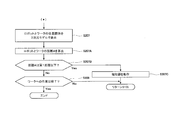
- FIGS. 20A and 20B are flowcharts showing an example of the operation of the robot system according to the third embodiment.
- the operation of the robot system 100 according to the third embodiment is an embodiment in that the processes of steps S207A to S207C are executed between steps S207 and S208. It is different from the operation of the robot system 100 according to 2.
- the arithmetic processor 112a of the second control device 112 includes the first data, the first position, and the second data acquired in the processes of steps S201 to S203, and the operation command information acquired in step S205.
- the positional relationship between the tip of the robot 101 (end effector 20) and the work 300 is displayed on the display device 105 in a three-dimensional model (step S207).
- the arithmetic processor 112a of the second control device 112 bases the robot 101 (3D robot 101A) and the work 300 (3D) based on the first data and the second data and the operation command information acquired in step S205.
- the distance A of the work 301) is calculated (step S207A).
- the arithmetic processor 112a of the second control device 112 calculates the distance between the portion of the robot 101 (3D robot 101A) closest to the work 300 (3D work 301) and the work 300 (3D work 301). You may.
- the arithmetic processor 112a of the second control device 112 is the distance between the tip of the end effector 20 and the work 300. Should be calculated.
- the arithmetic processor 1112 of the second control device 112 calculates the distance between the part of the robot 101 and the work 300. do it.
- the arithmetic processor 112a of the second control device 112 determines whether or not the distance A calculated in step S207A is equal to or less than a predetermined first distance set in advance (step S207B).
- the first distance can be set from the operating speed of the robot 101, the work content for the work 300, and the like.
- the first distance may be set small. Further, when the work on the work 300 is welding, cutting, cleaning, and polishing work, the first distance may be set small.
- the first distance when the operating speed of the robot 101 is high, the first distance may be set large. Further, even when the work on the work 300 is a liquid injection / spraying work, the first distance may be set large.
- the first distance may be, for example, 0.5 cm or more from the viewpoint of suppressing a collision with the work 300, or 30 cm from the viewpoint of executing the work on the work 300.
- the alarm 150 may be operated to collide with the work 300. Notify the warning that there is (step S207C). At this time, the arithmetic processing unit 112a of the second control device 112 may reduce the operating speed of the robot 101 or may stop the robot 101.
- the operator can recognize that the robot 101 may collide with the work 300, and the operator 102 can operate the robot 101 so as not to collide with the work 300.
- the arithmetic processor 112a of the second control device 112 acquires the operation command information input from the operator 102. That is, the arithmetic processor 112a of the second control device 112 returns to the process of step S205.
- step S207B when the arithmetic processor 112a of the second control device 112 determines that the distance A is not equal to or less than the first distance (No in step S207B), the operator passes the work through an input device (not shown) or the like. It is determined whether or not the instruction information indicating the end of the work has been input to the 300 (step S208).
- step S208 When the arithmetic processor 112a of the second control device 112 determines that the instruction information indicating the end of the work has not been input to the work 300 (No in step S208), the work is completed for the work 300. The process of step S205 to step S208 is repeated until it is determined that the instruction information indicating the above is input.
- the arithmetic processor 112a of the second control device 112 determines that the instruction information indicating the end of the work has been input to the work 300 (Yes in step S208), the arithmetic processor 112a ends this program.
- the robot system 100 according to the third embodiment also has the same effects as the robot system 100 according to the second embodiment.
- the present embodiment further includes a transport device 106 that transports the work 300 from the operation area 202 to a preset first position in the work area 201.
- a transport device 106 that transports the work 300 from the operation area 202 to a preset first position in the work area 201.
- the robot 101 is operated, the first operator 121 arranged in the operation area 202 is further provided, and the second control device 112 is the second data which is the data of the three-dimensional model of the robot 101.
- the second control device 112 has a storage device 112b in which the robot 101 is stored, and the operator operates the first controller 121 to operate the robot 101 to cause the work 300 to perform the work.
- the first data input in the output of the first data to the second control device 112, the position information of the first position of the conveyed workpiece, the second data, and the input from the first operator 121.
- the positional relationship between the work 300 and the tip of the robot 101 when viewed from a direction different from the direction in which the operator viewed the robot 101 from the operation area 202 is displayed on the display device 105.
- the operator can understand the positional relationship between the work 300 and the tip of the robot 101, which cannot be understood only by directly visually recognizing the robot 101 or the work 300.
- the 3D camera 103 is attached to the first actuator 121. According to this, since only one device should be grasped by the operator, the operation of the first actuator 121 and the operation of the 3D camera 103 become easy.
- the sensor 104 wirelessly detects the position information and the attitude information from the first actuator 121
- the second control device 112 wirelessly detects the position from the first actuator 121 detected by the sensor 104.
- the locus of the first actuator 121 may be calculated based on the information and the posture information, and a process (step S206) for operating the robot 101 in real time may be executed based on the calculated locus. This makes it easier to move the first actuator 121, so that the robot 101 can be operated accurately.
Landscapes
- Engineering & Computer Science (AREA)
- Robotics (AREA)
- Mechanical Engineering (AREA)
- Human Computer Interaction (AREA)
- Automation & Control Theory (AREA)
- Manipulator (AREA)
- Numerical Control (AREA)
- Image Analysis (AREA)
Abstract
Description
[ロボットシステムの構成]
図1は、本実施の形態1に係るロボットシステムの概略構成を示す模式図である。ロボットシステム100は、ロボット101、第1操作器121、3Dカメラ103、センサ104、表示装置105、第1制御装置111、及び第2制御装置112を備える。ロボット101及び第2制御装置112は、作業エリア201内に設置され、センサ104、表示装置105、及び第1制御装置111は、操作エリア202に配置されている。また、第1操作器121は、操作エリア202内において操作者に把持(保持)されて操作される。第1操作器121の先端部には、3Dカメラ103が配設されている。
次に、本実施の形態1に係るロボットシステム100の動作及び作用効果について、図1から図9を参照しながら、詳細に説明する。なお、以下の動作は、第1制御装置111の演算処理器111aが、記憶器111bに格納されているプログラムを読み出すことにより実行される。
図10は、本実施の形態1における変形例1のロボットシステムの概略構成を示す模式図である。本変形例1のロボットシステム100は、第1操作器121に検出器12および送信器13が設けられている点において、実施の形態1に係るロボットシステム100と異なる。検出器12は、第1操作器121及び3Dカメラ103の位置情報と姿勢情報とを無線通信により検出する。検出器12は、例えば、ジャイロセンサや、カメラである。送信器13は、検出器12により検出された位置情報と姿勢情報とを第1制御装置111に送信する本変形例1においては、検出器12と送信器13とがセンサ104に相当する。なお、検出器12は、位置情報と姿勢情報とを検出しなくてもよく、検出器12は、位置情報のみを検出してもよいし、姿勢情報のみを検出してもよい。
図11は、本実施の形態1における変形例2のロボットシステムの概略構成を示す模式図である。本変形例2のロボットシステム100は、3Dカメラ103がロボットアーム102の先端部に設けられている点と、第2操作器122を追加して備える点とにおいて、実施の形態1に係るロボットシステム100と異なる。
[ロボットシステムの構成]
図12は、本実施の形態2に係るロボットシステムの概略構成を示す模式図である。なお、図12においては、ロボットの方向を、便宜上、図に示す、三次元直交座標系のX軸、Y軸及びZ軸の方向で表わしている。本実施の形態2に係るロボットシステム100は、搬送装置106を追加して備える点と、において、実施の形態1(変形例を含む)に係るロボットシステムと異なる。搬送装置106は、ワークを操作エリアから作業エリアの予め設定されている第1位置に搬送する。搬送装置106は、ベルトコンベア等、公知の搬送装置である。
次に、本実施の形態2に係るロボットシステム100の動作及び作用効果について、図12から図14を参照しながら、詳細に説明する。なお、以下の動作は、第2制御装置112の演算処理器112aが、記憶器112bに格納されているプログラムを読み出すことにより実行される。
[ロボットシステムの構成]
図15は、本実施の形態2における変形例1のロボットシステムの概略構成を示す模式図である。本変形例1のロボットシステム100は、第2制御装置112が、センサ104から入力された第1操作器121の位置情報及び姿勢情報を基に、第1操作器121の先端部の動きに追従するように、ロボット101(エンドエフェクタ20)を動作させる点において、実施の形態2に係るロボットシステム100と異なる。
本実施の形態2における変形例1のロボットシステム100の動作及び作用効果について、図15及び図16を参照しながら、詳細に説明する。なお、以下の動作は、第2制御装置112の演算処理器112aが、記憶器112bに格納されているプログラムを読み出すことにより実行される。
図17及び図18は、本実施の形態2における変形例2のロボットシステムの概略構成を示す模式図である。なお、図17及び図18においては、ロボットの方向を、便宜上、図に示す、三次元直交座標系のX軸、Y軸及びZ軸の方向で表わしている。図17及び図18に示すように、本変形例2のロボットシステム100は、第2制御装置112が、ワーク300の3次元モデル情報に基づいて、当該ワーク300の予め設定されている所定の第1部分に対する法線方向を示すライン30を表示装置105に表示させる点において、実施の形態2に係るロボットシステム100と異なる。第1部分は、ロボット101のエンドエフェクタ20の先端と対向する部分であってもよい。
[ロボットシステムの構成]
図19は、本実施の形態3に係るロボットシステムの概略構成を示す模式図である。なお、図19においては、ロボットの方向を、便宜上、図に示す、三次元直交座標系のX軸、Y軸及びZ軸の方向で表わしている。
次に、本実施の形態3に係るロボットシステム100の動作及び作用効果について、図19、図20A、及び図20Bを参照しながら、詳細に説明する。なお、以下の動作は、第2制御装置112の演算処理器112aが、記憶器112bに格納されているプログラムを読み出すことにより実行される。
11b 第2リンク
11c 第3リンク
11d 第4リンク
11e 第5リンク
11f 第6リンク
12 検出器
13 送信器
15 基台
20 エンドエフェクタ
21 配管
100 ロボットシステム
101 ロボット
101A 3Dロボット
102 ロボットアーム
103 3Dカメラ
104 センサ
105 表示装置
106 搬送装置
107 シャッター
111 第1制御装置
111a 演算処理器
111b 記憶器
112 第2制御装置
112a 演算処理器
112b 記憶器
121 第1操作器
121A 把持部
121B スイッチ
121E 本体部
122 第2操作器
122B スイッチ
150 報知器
201 作業エリア
202 操作エリア
203 壁部材
204 窓
300 ワーク
301 3Dワーク
301A 3Dワーク
301B 3Dワーク
301C 3Dワーク
302A ワーク画像
302B ワーク画像
302C ワーク画像
JT1 第1関節
JT2 第2関節
JT3 第3関節
JT4 第4関節
JT5 第5関節
JT6 第6関節
Claims (13)
- 作業エリア内に設置され、第2制御装置により制御されるロボットと、
操作者により操作される3Dカメラと、
前記作業エリアとは異なる空間である操作エリアに配置され、前記3Dカメラの位置情報及び姿勢情報を無線により検出するセンサと、
表示装置と、
第1制御装置と、を備え、
前記第1制御装置は、
前記3Dカメラにより撮影されたワークの画像情報を取得し、
前記3Dカメラにより前記ワークが撮影されたときにおける前記位置情報及び前記姿勢情報を前記センサから取得し、
取得された前記画像情報を前記表示装置に表示させ、
前記画像情報と、取得された前記位置情報及び前記姿勢情報と、を基に、前記ワークの3次元モデルを形成し、
形成された前記3次元モデルを前記表示装置に表示させ、
形成された前記3次元モデルのデータである第1データを前記第2制御装置に出力する、ロボットシステム。 - 前記第1制御装置は、
前記画像情報の取得と、前記センサからの前記位置情報および前記姿勢情報の取得と、前記表示装置への前記画像情報の表示とを繰り返し実行した後、前記3Dモデルの形成と、前記表示装置への形成された前記3Dモデルの表示と、前記第2制御装置への前記第1データの出力とを実行する、請求項1に記載のロボットシステム。 - 前記第1制御装置は、
前記画像情報の取得と、前記センサからの前記位置情報および前記姿勢情報の取得と、前記表示装置への前記画像情報の表示と、前記3Dモデルの形成と、前記表示装置への形成された前記3Dモデルの表示とを実行した後、前記画像情報の取得と、前記センサからの前記位置情報および前記姿勢情報の取得と、前記表示装置への前記画像情報の表示とを1回以上繰り返し実行した後、
前記3Dモデルの形成において、A回目に取得された前記画像情報と、取得された前記位置情報及び前記姿勢情報と、を基に、前記3次元モデルを形成し、
形成された前記3次元モデルと、B回目(B≠A)に取得された前記画像情報と、を基に、前記3次元モデルを再形成し、
その後、前記表示装置への形成された前記3Dモデルの表示と、前記第2制御装置への前記第1データの出力とを実行する、請求項1又は請求項2に記載のロボットシステム。 - 前記第1制御装置は、
前記画像情報の取得と、前記センサからの前記位置情報および前記姿勢情報の取得と、前記表示装置への前記画像情報の表示と、前記3Dモデルの形成と、前記表示装置への形成された前記3Dモデルの表示と、を実行した後、前記画像情報の取得と、前記センサからの前記位置情報および前記姿勢情報の取得と、前記表示装置への前記画像情報の表示と、を1回以上繰り返し実行した後、
前記3Dモデルの形成において、C回目に取得された前記画像情報と、取得された前記位置情報及び前記姿勢情報と、を基に、前記3次元モデルを形成し、
D回目(D≠C)に取得された前記画像情報を基に、前記3次元モデルを形成し、
前記C回目に取得された前記画像情報と、取得された前記位置情報及び前記姿勢情報とに基づき形成された前記3次元モデルと、前記D回目(D≠C)に取得された前記画像情報に基づき形成された前記3次元モデルと、を基に、前記3次元モデルを再形成し、
その後、前記表示装置への形成された前記3Dモデルの表示と、前記第2制御装置への前記第1データの出力とを実行する、請求項1から請求項3までのいずれか1項に記載のロボットシステム。 - 前記ワークを前記操作エリアから前記作業エリアの予め設定されている第1位置に搬送する、搬送装置をさらに備える、請求項1から請求項4までのいずれか1項に記載のロボットシステム。
- 前記ロボットを操作し、前記操作エリアに配置されている第1操作器をさらに備え、
前記第2制御装置は、前記ロボットの3次元モデルのデータである第2データが記憶されている記憶器を有し、
前記第2制御装置は、
前記操作者が前記第1操作器を操作して、前記ロボットを動作させて、前記ワークに対して作業を実行させているときに、前記第2制御装置への前記第1データの出力で入力された前記第1データと、前記搬送された前記ワークの第1位置の位置情報と、前記第2データと、前記第1操作器から入力された前記ロボットの操作情報と、に基づいて、前記操作者が前記操作エリアから前記ロボットを見た方向とは異なる方向から見た場合の前記ワークと前記ロボットの先端部の位置関係を前記表示装置に表示させる、請求項1から請求項5までのいずれか1項に記載のロボットシステム。 - 前記第1操作器には、前記3Dカメラが取り付けられている、請求項6に記載のロボットシステム。
- 前記センサは、前記第1操作器からの前記位置情報及び前記姿勢情報を無線により検出し、
前記第2制御装置は、
前記センサにより検出された前記第1操作器からの前記位置情報及び前記姿勢情報を基に、前記第1操作器の軌跡を算出し、算出された前記軌跡に基づいて、リアルタイムで前記ロボットを動作させる、請求項7に記載のロボットシステム。 - 前記第2制御装置は、前記ロボットの3次元モデルのデータである第2データが記憶されている記憶器を有し、
前記第2制御装置は、
前記第2制御装置への前記第1データの出力で入力された前記第1データと、前記搬送された前記ワークの第1位置の位置情報と、前記第2データと、前記リアルタイムでの前記ロボットの動作で算出された前記軌跡と、に基づいて、前記操作者が前記操作エリアから前記ロボットを見た方向とは異なる方向から見た場合の前記ワークと前記ロボットの先端部の位置関係を前記表示装置に表示させる、請求項8に記載のロボットシステム。 - 前記作業エリアは、防爆エリアであり、前記操作エリアは、非防爆エリアである、請求項1から請求項9までのいずれか1項に記載のロボットシステム。
- 前記3Dカメラは、ロボットアームの先端部に設けられていて、
前記ロボットアームを操作する第2操作器をさらに備える、請求項1から請求項10までのいずれか1項に記載のロボットシステム。 - 前記第1制御装置は、前記第2制御装置を兼ねる、請求項1から請求項11までのいずれか1項に記載のロボットシステム。
- ロボットが設置されている作業エリアとは異なる空間である操作エリアに配置されているワークが前記3Dカメラにより撮影されたときにおける、前記3Dカメラの位置情報及び姿勢情報を検出し、
撮影された前記ワークの画像情報を取得し、
検出された前記位置情報及び前記姿勢情報を取得し、
取得された前記画像情報を前記表示装置に表示させ、
取得された前記画像情報と、取得された前記位置情報及び前記姿勢情報と、を基に、前記ワークの3次元モデルを形成する、ワークの3次元モデル形成方法。
Priority Applications (4)
| Application Number | Priority Date | Filing Date | Title |
|---|---|---|---|
| JP2021506354A JP6905651B1 (ja) | 2019-12-13 | 2020-12-11 | ロボットシステム及びワークの3次元モデルの形成方法 |
| CN202080069455.2A CN114502337B (zh) | 2019-12-13 | 2020-12-11 | 机器人系统以及工件的三维模型的形成方法 |
| EP20898730.5A EP4074474A4 (en) | 2019-12-13 | 2020-12-11 | ROBOT SYSTEM AND METHOD FOR PRODUCING A THREE-DIMENSIONAL MODEL OF A WORKPIECE |
| US17/784,118 US12246454B2 (en) | 2019-12-13 | 2020-12-11 | Robot system and method of forming three-dimensional model of workpiece |
Applications Claiming Priority (2)
| Application Number | Priority Date | Filing Date | Title |
|---|---|---|---|
| JP2019225562 | 2019-12-13 | ||
| JP2019-225562 | 2019-12-13 |
Publications (1)
| Publication Number | Publication Date |
|---|---|
| WO2021117868A1 true WO2021117868A1 (ja) | 2021-06-17 |
Family
ID=76330001
Family Applications (1)
| Application Number | Title | Priority Date | Filing Date |
|---|---|---|---|
| PCT/JP2020/046282 Ceased WO2021117868A1 (ja) | 2019-12-13 | 2020-12-11 | ロボットシステム及びワークの3次元モデルの形成方法 |
Country Status (5)
| Country | Link |
|---|---|
| US (1) | US12246454B2 (ja) |
| EP (1) | EP4074474A4 (ja) |
| JP (1) | JP6905651B1 (ja) |
| CN (1) | CN114502337B (ja) |
| WO (1) | WO2021117868A1 (ja) |
Cited By (1)
| Publication number | Priority date | Publication date | Assignee | Title |
|---|---|---|---|---|
| WO2023079652A1 (ja) * | 2021-11-04 | 2023-05-11 | ファナック株式会社 | 制御装置、制御方法、及びクラウドシステム |
Families Citing this family (2)
| Publication number | Priority date | Publication date | Assignee | Title |
|---|---|---|---|---|
| US12504741B2 (en) * | 2021-07-09 | 2025-12-23 | Florida Atlantic University Board Of Trustees | Adaptive cyber manufacturing (ACM) through online human-AI partnerships |
| JP7582145B2 (ja) * | 2021-09-24 | 2024-11-13 | 村田機械株式会社 | ワーク位置判定装置、レーザ加工装置、及びワーク位置判定方法 |
Citations (6)
| Publication number | Priority date | Publication date | Assignee | Title |
|---|---|---|---|---|
| JP2011516849A (ja) * | 2008-04-02 | 2011-05-26 | エイコナ・テクノロジーズ・リミテッド | 3d撮像システム |
| JP2012111029A (ja) * | 2010-11-19 | 2012-06-14 | Fanuc Robotics America Corp | 3次元ロボットワークセルデータの表示システム、表示方法及び表示装置 |
| JP2012135858A (ja) * | 2010-12-28 | 2012-07-19 | Toyota Motor Corp | 操作環境モデル構築システム、および操作環境モデル構築方法 |
| JP2016534461A (ja) * | 2013-08-30 | 2016-11-04 | クアルコム,インコーポレイテッド | 物理的光景を表すための方法および装置 |
| JP2018158391A (ja) * | 2017-03-22 | 2018-10-11 | 株式会社東芝 | 物体ハンドリング装置およびその較正方法 |
| JP2018192602A (ja) * | 2017-05-19 | 2018-12-06 | 川崎重工業株式会社 | 作業方法およびロボットシステム |
Family Cites Families (19)
| Publication number | Priority date | Publication date | Assignee | Title |
|---|---|---|---|---|
| JP2961264B1 (ja) * | 1998-09-21 | 1999-10-12 | 工業技術院長 | 3次元物体モデル生成方法及び3次元物体モデル生成プログラムを記録したコンピュータ読み取り可能な記録媒体 |
| GB0023681D0 (en) * | 2000-09-27 | 2000-11-08 | Canon Kk | Image processing apparatus |
| JP2004046542A (ja) * | 2002-07-11 | 2004-02-12 | Mitsubishi Heavy Ind Ltd | モデル加工方法およびモデル加工システム |
| JP5843359B2 (ja) * | 2012-03-29 | 2016-01-13 | 株式会社Jsol | 情報処理システム、サーバ装置、端末装置、情報処理装置、情報処理方法、およびプログラム |
| JP5670397B2 (ja) * | 2012-08-29 | 2015-02-18 | ファナック株式会社 | バラ積みされた物品をロボットで取出す装置及び方法 |
| JP6344890B2 (ja) * | 2013-05-22 | 2018-06-20 | 川崎重工業株式会社 | 部品組立作業支援システムおよび部品組立方法 |
| US9643314B2 (en) * | 2015-03-04 | 2017-05-09 | The Johns Hopkins University | Robot control, training and collaboration in an immersive virtual reality environment |
| JP6723738B2 (ja) * | 2015-04-03 | 2020-07-15 | キヤノン株式会社 | 情報処理装置、情報処理方法及びプログラム |
| WO2017204826A1 (en) * | 2016-05-27 | 2017-11-30 | Abb Schweiz Ag | User interface for a teleoperated robot |
| JP6582921B2 (ja) * | 2015-11-26 | 2019-10-02 | 株式会社デンソーウェーブ | ロボットモニタシステム |
| JP6300120B2 (ja) * | 2015-12-28 | 2018-03-28 | 株式会社ニイガタマシンテクノ | 制御用データ生成方法および制御用データ生成装置 |
| DE102016106696A1 (de) * | 2016-04-12 | 2017-10-12 | Carl Zeiss Industrielle Messtechnik Gmbh | Koordinatenmesssystem |
| JP6880982B2 (ja) * | 2017-04-21 | 2021-06-02 | セイコーエプソン株式会社 | 制御装置およびロボットシステム |
| TWI650626B (zh) * | 2017-08-15 | 2019-02-11 | 由田新技股份有限公司 | 基於三維影像之機械手臂加工方法及系統 |
| CN107908152A (zh) * | 2017-12-26 | 2018-04-13 | 苏州瀚华智造智能技术有限公司 | 一种活动式机器人自动喷涂装置、控制系统及方法 |
| JP6845180B2 (ja) * | 2018-04-16 | 2021-03-17 | ファナック株式会社 | 制御装置及び制御システム |
| JP7384575B2 (ja) * | 2018-08-10 | 2023-11-21 | 川崎重工業株式会社 | 情報処理装置、仲介装置、シミュレートシステム、情報処理方法及びプログラム |
| JP6895128B2 (ja) * | 2018-11-09 | 2021-06-30 | オムロン株式会社 | ロボット制御装置、シミュレーション方法、及びシミュレーションプログラム |
| KR102619004B1 (ko) * | 2018-12-14 | 2023-12-29 | 삼성전자 주식회사 | 로봇 장치 및 로봇의 작업 기술을 학습하는 방법 |
-
2020
- 2020-12-11 WO PCT/JP2020/046282 patent/WO2021117868A1/ja not_active Ceased
- 2020-12-11 CN CN202080069455.2A patent/CN114502337B/zh active Active
- 2020-12-11 US US17/784,118 patent/US12246454B2/en active Active
- 2020-12-11 JP JP2021506354A patent/JP6905651B1/ja active Active
- 2020-12-11 EP EP20898730.5A patent/EP4074474A4/en active Pending
Patent Citations (7)
| Publication number | Priority date | Publication date | Assignee | Title |
|---|---|---|---|---|
| JP2011516849A (ja) * | 2008-04-02 | 2011-05-26 | エイコナ・テクノロジーズ・リミテッド | 3d撮像システム |
| JP2012111029A (ja) * | 2010-11-19 | 2012-06-14 | Fanuc Robotics America Corp | 3次元ロボットワークセルデータの表示システム、表示方法及び表示装置 |
| JP2019177477A (ja) | 2010-11-19 | 2019-10-17 | ファナック アメリカ コーポレイション | 3次元ロボットワークセルデータの表示システム、表示方法及び表示装置 |
| JP2012135858A (ja) * | 2010-12-28 | 2012-07-19 | Toyota Motor Corp | 操作環境モデル構築システム、および操作環境モデル構築方法 |
| JP2016534461A (ja) * | 2013-08-30 | 2016-11-04 | クアルコム,インコーポレイテッド | 物理的光景を表すための方法および装置 |
| JP2018158391A (ja) * | 2017-03-22 | 2018-10-11 | 株式会社東芝 | 物体ハンドリング装置およびその較正方法 |
| JP2018192602A (ja) * | 2017-05-19 | 2018-12-06 | 川崎重工業株式会社 | 作業方法およびロボットシステム |
Non-Patent Citations (1)
| Title |
|---|
| See also references of EP4074474A4 |
Cited By (1)
| Publication number | Priority date | Publication date | Assignee | Title |
|---|---|---|---|---|
| WO2023079652A1 (ja) * | 2021-11-04 | 2023-05-11 | ファナック株式会社 | 制御装置、制御方法、及びクラウドシステム |
Also Published As
| Publication number | Publication date |
|---|---|
| CN114502337A (zh) | 2022-05-13 |
| US20230028457A1 (en) | 2023-01-26 |
| JP6905651B1 (ja) | 2021-07-21 |
| EP4074474A4 (en) | 2024-06-05 |
| JPWO2021117868A1 (ja) | 2021-12-09 |
| US12246454B2 (en) | 2025-03-11 |
| EP4074474A1 (en) | 2022-10-19 |
| CN114502337B (zh) | 2024-01-09 |
Similar Documents
| Publication | Publication Date | Title |
|---|---|---|
| CN110394780B (zh) | 机器人的仿真装置 | |
| TWI609748B (zh) | 遠端操作機器人系統 | |
| CN111093903B (zh) | 机器人系统及其运行方法 | |
| US10635082B2 (en) | Robot motion program generating method and robot motion program generating apparatus | |
| CN110977931A (zh) | 使用了增强现实和混合现实的机器人控制装置及显示装置 | |
| JP6905651B1 (ja) | ロボットシステム及びワークの3次元モデルの形成方法 | |
| JP6821374B2 (ja) | ロボットシステム及びその運転方法 | |
| CN111093911B (zh) | 机器人系统及其运行方法 | |
| US20120127165A1 (en) | System, method, and apparatus to display three-dimensional robotic workcell data | |
| JP6990340B2 (ja) | ロボットシステム | |
| KR102681939B1 (ko) | 로봇시스템 | |
| JP7594643B2 (ja) | ロボットシステム | |
| JPH1177568A (ja) | 教示支援方法及び装置 | |
| JP7462046B2 (ja) | ロボットシステム | |
| WO2024047808A1 (ja) | ロボット座標系に搬送装置座標系を設定する装置、及び方法 |
Legal Events
| Date | Code | Title | Description |
|---|---|---|---|
| ENP | Entry into the national phase |
Ref document number: 2021506354 Country of ref document: JP Kind code of ref document: A |
|
| 121 | Ep: the epo has been informed by wipo that ep was designated in this application |
Ref document number: 20898730 Country of ref document: EP Kind code of ref document: A1 |
|
| NENP | Non-entry into the national phase |
Ref country code: DE |
|
| ENP | Entry into the national phase |
Ref document number: 2020898730 Country of ref document: EP Effective date: 20220713 |
|
| WWG | Wipo information: grant in national office |
Ref document number: 17784118 Country of ref document: US |