WO2021129043A1 - Dispositif de guidage de fondation monopieu - Google Patents
Dispositif de guidage de fondation monopieu Download PDFInfo
- Publication number
- WO2021129043A1 WO2021129043A1 PCT/CN2020/120148 CN2020120148W WO2021129043A1 WO 2021129043 A1 WO2021129043 A1 WO 2021129043A1 CN 2020120148 W CN2020120148 W CN 2020120148W WO 2021129043 A1 WO2021129043 A1 WO 2021129043A1
- Authority
- WO
- WIPO (PCT)
- Prior art keywords
- unit
- pile foundation
- clamping
- guiding device
- roller
- Prior art date
- Legal status (The legal status is an assumption and is not a legal conclusion. Google has not performed a legal analysis and makes no representation as to the accuracy of the status listed.)
- Ceased
Links
Images




Classifications
-
- E—FIXED CONSTRUCTIONS
- E02—HYDRAULIC ENGINEERING; FOUNDATIONS; SOIL SHIFTING
- E02D—FOUNDATIONS; EXCAVATIONS; EMBANKMENTS; UNDERGROUND OR UNDERWATER STRUCTURES
- E02D13/00—Accessories for placing or removing piles or bulkheads, e.g. noise attenuating chambers
- E02D13/04—Guide devices; Guide frames
-
- E—FIXED CONSTRUCTIONS
- E02—HYDRAULIC ENGINEERING; FOUNDATIONS; SOIL SHIFTING
- E02D—FOUNDATIONS; EXCAVATIONS; EMBANKMENTS; UNDERGROUND OR UNDERWATER STRUCTURES
- E02D27/00—Foundations as substructures
- E02D27/10—Deep foundations
- E02D27/12—Pile foundations
- E02D27/16—Foundations formed of separate piles
-
- E—FIXED CONSTRUCTIONS
- E02—HYDRAULIC ENGINEERING; FOUNDATIONS; SOIL SHIFTING
- E02D—FOUNDATIONS; EXCAVATIONS; EMBANKMENTS; UNDERGROUND OR UNDERWATER STRUCTURES
- E02D27/00—Foundations as substructures
- E02D27/32—Foundations for special purposes
- E02D27/52—Submerged foundations, i.e. submerged in open water
-
- F—MECHANICAL ENGINEERING; LIGHTING; HEATING; WEAPONS; BLASTING
- F03—MACHINES OR ENGINES FOR LIQUIDS; WIND, SPRING, OR WEIGHT MOTORS; PRODUCING MECHANICAL POWER OR A REACTIVE PROPULSIVE THRUST, NOT OTHERWISE PROVIDED FOR
- F03D—WIND MOTORS
- F03D13/00—Assembly, mounting or commissioning of wind motors; Arrangements specially adapted for transporting wind motor components
- F03D13/20—Arrangements for mounting or supporting wind motors; Masts or towers for wind motors
- F03D13/22—Foundations specially adapted for wind motors
-
- F—MECHANICAL ENGINEERING; LIGHTING; HEATING; WEAPONS; BLASTING
- F03—MACHINES OR ENGINES FOR LIQUIDS; WIND, SPRING, OR WEIGHT MOTORS; PRODUCING MECHANICAL POWER OR A REACTIVE PROPULSIVE THRUST, NOT OTHERWISE PROVIDED FOR
- F03D—WIND MOTORS
- F03D13/00—Assembly, mounting or commissioning of wind motors; Arrangements specially adapted for transporting wind motor components
- F03D13/20—Arrangements for mounting or supporting wind motors; Masts or towers for wind motors
- F03D13/25—Arrangements for mounting or supporting wind motors; Masts or towers for wind motors specially adapted for offshore installation
-
- E—FIXED CONSTRUCTIONS
- E02—HYDRAULIC ENGINEERING; FOUNDATIONS; SOIL SHIFTING
- E02D—FOUNDATIONS; EXCAVATIONS; EMBANKMENTS; UNDERGROUND OR UNDERWATER STRUCTURES
- E02D27/00—Foundations as substructures
- E02D27/32—Foundations for special purposes
- E02D27/42—Foundations for poles, masts or chimneys
-
- E—FIXED CONSTRUCTIONS
- E02—HYDRAULIC ENGINEERING; FOUNDATIONS; SOIL SHIFTING
- E02D—FOUNDATIONS; EXCAVATIONS; EMBANKMENTS; UNDERGROUND OR UNDERWATER STRUCTURES
- E02D27/00—Foundations as substructures
- E02D27/32—Foundations for special purposes
- E02D27/52—Submerged foundations, i.e. submerged in open water
- E02D27/525—Submerged foundations, i.e. submerged in open water using elements penetrating the underwater ground
-
- Y—GENERAL TAGGING OF NEW TECHNOLOGICAL DEVELOPMENTS; GENERAL TAGGING OF CROSS-SECTIONAL TECHNOLOGIES SPANNING OVER SEVERAL SECTIONS OF THE IPC; TECHNICAL SUBJECTS COVERED BY FORMER USPC CROSS-REFERENCE ART COLLECTIONS [XRACs] AND DIGESTS
- Y02—TECHNOLOGIES OR APPLICATIONS FOR MITIGATION OR ADAPTATION AGAINST CLIMATE CHANGE
- Y02E—REDUCTION OF GREENHOUSE GAS [GHG] EMISSIONS, RELATED TO ENERGY GENERATION, TRANSMISSION OR DISTRIBUTION
- Y02E10/00—Energy generation through renewable energy sources
- Y02E10/70—Wind energy
- Y02E10/72—Wind turbines with rotation axis in wind direction
-
- Y—GENERAL TAGGING OF NEW TECHNOLOGICAL DEVELOPMENTS; GENERAL TAGGING OF CROSS-SECTIONAL TECHNOLOGIES SPANNING OVER SEVERAL SECTIONS OF THE IPC; TECHNICAL SUBJECTS COVERED BY FORMER USPC CROSS-REFERENCE ART COLLECTIONS [XRACs] AND DIGESTS
- Y02—TECHNOLOGIES OR APPLICATIONS FOR MITIGATION OR ADAPTATION AGAINST CLIMATE CHANGE
- Y02E—REDUCTION OF GREENHOUSE GAS [GHG] EMISSIONS, RELATED TO ENERGY GENERATION, TRANSMISSION OR DISTRIBUTION
- Y02E10/00—Energy generation through renewable energy sources
- Y02E10/70—Wind energy
- Y02E10/727—Offshore wind turbines
Definitions
- the present disclosure relates to the technical field of offshore wind power generation, and more specifically, to a single pile foundation guiding device for offshore wind power generating sets.
- the single pile foundation has the advantages of simple manufacturing and low equipment cost requirements, as well as superior construction efficiency. Therefore, more than 90% of offshore wind turbines use a single pile foundation.
- the verticality requirements of the single pile foundation are extremely high, and the maximum height difference of the circumferential plane needs to be less than the set value.
- the single pile foundation In the process of hammering the single pile foundation to penetrate the seabed, if there is a deviation in hammering, the single pile foundation is likely to be scrapped. From the later repair plan to the implementation or reconnection of the transition flange to correct the vertical
- the cost of offshore construction vessels and cranes will be huge losses. Therefore, verticality control is the key to single pile foundation construction.
- Some single-pile foundation guiding devices in the prior art use multiple oil cylinder structures to clamp the single-pile foundation at multiple different positions, which makes it difficult to perform synchronization operations and has low vertical synchronization control accuracy.
- the extension length of each oil cylinder needs to be measured every time.
- the hammering of the single pile it is necessary to pay attention to the force of each oil cylinder at any time. In this case, every time a single pile drops a certain height, it is necessary to stop the hammer and measure the verticality. If there is a deviation, it is necessary to push each oil cylinder to adjust the verticality of the single pile again.
- Such reciprocation makes the operation process complicated and low efficiency.
- the oil cylinder is installed on the top of the platform, and the operator needs to climb to the top of the platform to operate the oil cylinder and measure the extension length of the oil cylinder, and there is a risk of personnel falling.
- the purpose of the present disclosure is to provide a single-pile foundation guiding device with simple operation, high safety performance and capable of accurately controlling the verticality of the single-pile foundation.
- the single-pile foundation guiding device includes at least one guiding unit, and each of the at least one guiding unit includes a single driving unit, a transmission unit, and a clamping unit.
- the clamping unit includes at least two clamping arms, a clamping space for clamping a single pile foundation is formed between the at least two clamping arms, and the single driving unit transmits power to the transmission The unit drives the at least two clamping arms to operate synchronously through the transmission unit, so that the clamping unit is opened or closed.
- the at least one guide unit includes a first guide unit, the first guide unit includes a first drive unit, a first transmission unit, and a first clamping unit, and the first transmission unit includes a pusher Block, the first driving unit pushes the push block to move so as to drive the first clamping unit to close to hold the mono-pile foundation tightly.
- the at least one guide unit includes a second guide unit, the second guide unit includes a second drive unit, a second transmission unit, and a second clamping unit, and the second transmission unit includes a ring-shaped Frame, the second clamping unit includes a plurality of clamping arms, the plurality of clamping arms are inserted into the ring frame, and the second driving unit pushes the ring frame to rotate so as to pass through the ring frame Drive the plurality of clamping arms to pivot synchronously.
- the present disclosure abandons the traditional three-cylinder or four-cylinder oil cylinder, controls the pushing form of the clamping arm separately, adopts a single drive structure, and each clamping arm pivots synchronously and concentrically, which can realize the precise control of the verticality in the single pile construction process, and the operation is simple ,
- the force is stable, safe and reliable.
- Fig. 1 is a perspective view of a single pile foundation guiding device according to a first embodiment of the present disclosure
- Fig. 2 is a state diagram of a single-pile foundation construction using the single-pile foundation guiding device according to the first embodiment of the present disclosure
- FIG. 3 is a perspective view of the first guide unit of the single pile foundation guide device according to the first embodiment of the present disclosure
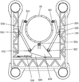
- FIG. 4 is a top view of the first guide unit of the single pile foundation guide device according to the first embodiment of the present disclosure, wherein the first clamping unit is in a closed state;
- FIG. 5 is a top view of the first guide unit of the single pile foundation guide device according to the first embodiment of the present disclosure, wherein the first clamping unit is in an open state;
- Fig. 6 is a perspective view of a single pile foundation guiding device according to a second embodiment of the present disclosure.
- Fig. 7 is a perspective view of a second guiding unit of the single pile foundation guiding device according to the second embodiment of the present disclosure.
- FIG. 8 is a top view of the second guide unit of the single pile foundation guide device according to the second embodiment of the present disclosure, wherein the second clamping unit is in a closed state;
- Fig. 9 is a top view of the second guiding unit of the single pile foundation guiding device according to the second embodiment of the present disclosure, wherein the second clamping unit is in an open state.
- the single pile foundation guiding device includes at least one guiding unit, and each guiding unit may include a single driving unit, a transmission unit, and a clamping unit.
- the power is transmitted to the transmission unit through the single driving unit, and the clamping unit is driven by the transmission unit.
- At least two clamping arms operate synchronously, so that multiple clamping arms of the clamping unit can be opened or closed at the same time, ensuring the synchronization control accuracy of the verticality of the single pile foundation.
- Figures 1 to 5 show schematic structural diagrams of a single pile foundation guiding device according to the first embodiment of the present disclosure.
- the single pile foundation guiding device includes a guiding support frame 100 and a first guiding unit 1000 provided on the guiding support frame 100.
- the guiding support frame 100 includes a plurality of positioning piles 110 and a first supporting platform 120 fixed on the positioning piles 110.
- the positioning pile 110 is a columnar structure, and the first supporting platform 120 is welded or bolted to the positioning pile 110.
- the positioning pile 110 can be connected to the hull of the ship or penetrate the seabed to form a stable supporting structure.
- there are four positioning piles 110 which are enclosed in a rectangular shape.
- the first supporting platform 120 is formed as a rectangular frame with one side open, and the four corners are respectively fixedly connected with the positioning piles 110.
- the number of the positioning piles 110 of the guide support frame 100 of the present disclosure is not limited to this.
- the positioning piles 110 may be at least three.
- the shape of the first supporting platform 120 is not limited to a rectangle, and may also be a circle or a semicircle, as long as the inner side It is sufficient to form a space suitable for installing the first guide unit 1000.
- the first guide unit 1000 is installed on the first supporting platform 120.
- the first support platform 120 is formed as a concave structure with one side open, and the first guide unit 1000 is installed in the recess of the first support platform 120 for guiding the single pile foundation 10 when the single pile foundation 10 is hoisted, and In the process of hammering the single-pile foundation, a clamping force is applied to the single-pile foundation 10 to ensure the verticality of the single-pile foundation 10.
- the first guide unit 1000 may include a first driving unit 300, a first transmission unit 400 and a first clamping unit 500.
- the first clamping unit 500 has a clamping space for accommodating the single pile foundation 10.
- the first driving unit 300 transmits the driving force to the first transmission unit 400, and the first clamping unit 500 is driven to close or open through the first transmission unit 400 to hold or loosen the monopile foundation 10 tightly.
- the specific structure of the first guide unit 1000 will be described in more detail.
- the first clamping unit 500 may include a first clamping arm 510 and a second clamping arm 520.
- the first clamping arm 510 and the second clamping arm 520 may have a symmetrical structure, and an accommodation space for accommodating the single pile foundation 10 is formed between the first clamping arm 510 and the second clamping arm 520.
- the inner side wall of the first support platform 120 may include a first inner side wall 121, a second inner side wall 122 and a third inner side wall 123 located on both sides of the first inner side wall 121, a first clamping arm 510 and a second clamp
- the holding arms 520 may be respectively installed on the second inner side wall 122 and the third inner side wall 123 of the first support platform 120.
- a first squeezing roller 511 may be provided on the first end of the first clamping arm 510, and a first supporting roller 512 may be provided on the second end.
- the first clamping arm 510 may be hinged to the first support platform 120.
- the first clamping arm 510 may be a rigid curved connecting rod, which is hinged to the first support through a first hinge shaft 515 at the middle position of the rigid curved connecting rod.
- the first clamping arm 510 can pivot around the first hinge shaft 515 within a certain angle range.
- a second squeeze roller 521 may be provided on the first end of the second clamping arm 520, and a second support roller 522 may be provided on the second end.
- the second clamping arm 520 may be hinged to the first support platform 120.
- the second clamping arm 520 may be a rigid curved connecting rod, which is hinged to the first support through a second hinged shaft 525 at the middle position of the rigid curved connecting rod.
- the second clamping arm 520 can pivot around the second hinge shaft 525 within a certain angle range.
- the first transmission unit 400 may include a pushing block 410, and the first driving unit 300 pushes the pushing block 410 to move toward the clamping space of the first clamping unit 500, thereby driving the first clamping unit 500 to close to hold the monopile foundation 10 tightly.
- a limit mechanism can be provided on the first support platform 120 to limit the movement trajectory of the push block 410.
- a groove is provided on the first support platform 120, and a protrusion matching the groove is provided on the lower surface of the push block 410. So that the protrusion is locked in the groove and can move in the groove.
- the limit mechanism guides the movement of the push block 410 so that the push block 410 can only move along a specific track, so as to apply a stable driving force to the first clamping unit 500.
- the pushing block 410 may include a first tapered surface 411 and a second tapered surface 412 oppositely disposed. Specifically, the distance between the first tapered surface 411 and the second tapered surface 412 decreases toward the clamping space, so that the top of the cone formed by the push block 410 faces the clamping space.
- the first clamping arm 510 abuts on the first tapered surface 411 via the first support roller 512
- the second clamping arm 520 abuts on the second tapered surface 412 via the second support roller 522.
- the first support roller 512 can roll along the first tapered surface 411
- the second support roller 522 can roll along the second tapered surface 412.
- the first driving unit 300 pushes the push block 410 toward the clamping space
- the first tapered surface 411 and the second tapered surface 412 on both sides of the push block 410 respectively transfer forces to the first support roller 512 and the second support roller 522 , Thereby pushing the first clamping arm 510 and the second clamping arm 520 to pivot around the hinge shafts 515 and 525, respectively.
- the first squeezing roller 511 and the second squeezing roller 521 will move toward the clamping space to Adjust the size of the clamping space or adjust the pressing force to the single pile foundation 10.
- the first clamping unit 500 may further include a third clamping arm, and the third clamping arm may be fixedly installed on the push block 410 and located on the push block 410. On the side facing the clamping space.
- a third squeeze roller 531 may be installed on the third clamping arm.
- the third clamping arm is shorter and is formed as a roller bracket for mounting the third squeezing roller 531 on the push block 410, and the roller bracket can be welded and fixed with the push block 410.
- the first squeeze roller 511, the second squeeze roller 521, and the third squeeze roller 531 can move synchronously and coaxially while abutting the outer surface of the single pile foundation 10 and simultaneously A holding force is applied to the single-pile foundation 10, so that the single-pile foundation 10 is subjected to a symmetrical pressing force in the circumferential direction, so as to ensure the verticality of the single-pile foundation 10.
- the third clamping arm is not necessary.
- the end of the first clamping arm 510 where the first pressing roller 511 is installed may be formed with an arc-shaped splint to surround a part of the outer circumference of the mono-pile foundation on the outside of the mono-pile foundation.
- a plurality of squeezing rollers may also be provided on the inner surface of the arc-shaped splint to make rolling contact with the outer surface of the single pile foundation through the plurality of squeezing rollers.
- the end of the second clamping arm 520 where the second pressing roller 521 is installed is also formed with an arc-shaped splint, and a plurality of pressing rollers can also be installed on the inner side of the arc-shaped splint.
- the pushing block 410 pushes the first clamping arm 510 and the second clamping arm 520 to pivotally close, the two arc-shaped splints symmetrically squeeze the single pile foundation from both sides of the single pile foundation, thereby holding the single pile foundation tightly. Ensure the verticality of the single pile foundation.
- the push block 410 is driven by a single driving unit 300, and a plurality of clamping arms are driven by the push block 410 to operate synchronously, so that a plurality of squeezing rollers abut the outer surface of the monopile foundation 10 at the same time.
- the structure and installation position of the first driving unit 300 are not limited, as long as the first driving unit 300 can push the push block 410 to move toward the clamping space, pushing the first clamping arm 510 and the second clamping arm 520 It can be pivoted synchronously.
- an example of implementing the first driving unit 300 is provided.
- the pushing block 410 further includes a first inclined surface 413, and the first tapered surface 411 and the second tapered surface 412 are located on both sides of the first inclined surface 413.
- the first inclined surface 413 is formed on the side of the push block 410 facing away from the clamping space.
- the first driving unit 300 includes a hydraulic cylinder 310 and a wedge 320 connected to one end of the hydraulic cylinder.
- the wedge 320 has a second inclined surface 321.
- the second inclined surface 321 faces the first inclined surface 413 and is in contact with each other.
- the first driving unit 300 can be installed on the first inner side wall 121 of the first support platform 120, and the wedge 320 can slide on the first inner side wall 121 along the first direction, thereby driving the hydraulic cylinder 310 along the first direction.
- the driving force is converted into power for the push block 410 to move in the second direction.
- protrusions can be provided on the wedge block 320 and the push block 410, and corresponding grooves can be provided on the first support platform 120. By setting the protrusions on The groove guides the movement route of the wedge block 320 and the push block 410.
- the three squeezing rollers 511, 521, and 531 can be arranged evenly and symmetrically along the outer circumference of the single pile foundation 10.
- the taper of the first tapered surface 411 and the second tapered surface 412 of the push block 410 can be designed.
- the three squeezing rollers 511, 521, and 531 apply the same squeezing force to the single pile foundation 10.
- the inclination angle of the surface of the pushing block 410 facing the clamping space can also be adjusted.
- the three squeezing rollers are not necessarily arranged uniformly, as long as the single pile foundation 10 can be symmetrical in force in all directions.
- the first supporting platform 120 may further include a horizontal supporting plate supporting the first driving unit 300 and the first transmission unit 400.
- a horizontal support plate may be provided under the push block 410 and the wedge 320 to support the bottom surface of the push block 410 and the wedge 320 so that the push block 410 and the wedge 320 slide stably in the horizontal direction.
- the first supporting roller 512 is rotatably supported on the first tapered surface 411 of the pushing block 410
- the second supporting roller 522 is rotatably supported on the second tapered surface 412 of the pushing block 410.
- the push block 410 pushes the first support roller 512 and the second support roller 522 to both sides through the first tapered surface 411 and the second tapered surface 412, respectively, and drives the first clamping arm 510 and the second clamping arm 520 pivot around the hinge shafts 515 and 525, so that the first squeezing roller 511 and the second squeezing roller 521 move inward with respect to the clamping space, and abut the outer surface of the single pile foundation 10, A holding force is applied to the single pile foundation 10.
- FIG. 4 shows a schematic diagram in which the first clamping unit 500 is closed to apply a holding force to the single pile foundation 10.
- the wedge 320 may be a triangular wedge, preferably a right-angled triangular wedge.
- the cross-sectional shape of the wedge block 320 may be a right-angled triangle, and the long right-angled side (also called the base side) of the triangle faces and contacts the first inner side wall 121 of the first support platform 120 so as to be in contact with the first inner side wall 121 of the first supporting platform 120.
- the inner side wall 121 slides up.
- the short right-angled side of the triangle is perpendicular to the first inner side wall 121, and the first driving unit 300 may be connected to the short right-angled side of the wedge 320.
- the inclined surface (ie, the second inclined surface 321) of the wedge block 320 corresponding to the hypotenuse of the triangle and the first inclined surface 413 of the push block 410 face and contact.
- the pushing block 410 is located between the wedge block 320 and the clamping space.
- the inclination angle of the first inclined surface 413 and the second inclined surface 321 may be 10°-30°, preferably 20°.
- the angle of inclination is small, the contact area between the first inclined surface 413 and the second inclined surface 321 is large, the stroke of the cylinder is large, and the adjustment speed is slow.
- the angle of inclination is large, the contact area between the first inclined surface 413 and the second inclined surface 321 is small, the stroke of the cylinder is small, and the adjustment speed is fast. Therefore, the inclination angles of the first inclined surface 413 and the second inclined surface 321 can be set according to adjustment requirements.
- the wedge block 320 pushes the push block 410 outwards, pushes the push block 410 away from the first inner side wall 121, and moves toward the clamping space of the first guide unit 500.
- the wedge block 320 retracts, thereby canceling the pushing force on the pushing block 410.
- the push block 410 also needs to retract at the same time.
- the two inclined surfaces 321 and 413 on which the wedge block 320 and the push block 410 abut can be provided with sliding grooves and sliding rails, respectively, and the sliding rails can be locked in the sliding In the groove, the wedge block 320 and the push block 410 can be movably connected to each other, so that the push block 410 can move together with the wedge block 320.
- the push block 410 can also retreat toward the first inner side wall 121 , Away from the clamping space.
- the solution for retracting the push block 410 is not limited to this, and a return spring may be provided on the first inner side wall 121 to apply a pulling force to the push block 410, so that when the wedge block 320 retracts, The pushing block 410 can also move toward the first inner side wall 121 under the pulling force of the return spring.
- FIG. 5 shows a schematic diagram of the first clamping unit 500 in an open state.
- a reset can be provided on the first hinge shaft 515 and the second hinge shaft 525 Spring, so that when the push block 410 retreats and cancels the pushing force on the first support roller 512 and the second support roller 522, the outer ends of the first clamping arm 510 and the second clamping arm 520 can act on the elastic force of the return spring Open outward from the bottom.
- the return spring may also be provided on the second inner side wall 122 and the third inner side wall 123.
- roller grooves can also be provided on the first tapered surface 411 and the second tapered surface 412, and the first support roller 512 and the second support roller 522 are embedded in the roller grooves.
- the supporting roller 522 can be engaged in the roller groove and can roll in the roller groove.
- the first supporting roller 512 and the second supporting roller 522 cannot be disengaged from the first tapered surface 411 and the second tapered surface 412 of the pushing block 410. Therefore, the pushing block 410 is far away from the clamping space.
- first support roller 512 and the second support roller 522 roll toward the top end of the push block 410 along the first tapered surface 411 and the second tapered surface 412, so that the first clamping arm 510 and the second clamping arm 520 respectively surround The hinge shafts 515 and 525 pivot to open the clamping space.
- the rolling path of the roller is designed with a difference between horizontal and vertical.
- the rolling path of the roller contacting the single pile foundation 10 is along the vertical direction
- the rolling path of the roller contacting the push block 410 is along the vertical direction. Along the horizontal direction.
- a single driving unit 300 can realize synchronous coaxial movement of a plurality of squeezing rollers of the first clamping unit 500.
- a hydraulic cylinder When a hydraulic cylinder is used for driving, only one cylinder needs to be controlled, which greatly reduces the installation and subsequent maintenance costs of multiple cylinders.
- the two tapered surfaces of the push block 410 transmit the thrust to the supporting rollers, so that stepless adjustment of the pivoting angle of the clamping arm can be achieved.
- the extension length of the hydraulic cylinder of the first driving unit 300 the size of the clamping space formed by the first clamping unit 500 can be adjusted, so as to meet the guiding requirements for single pile foundations of different diameters.
- the single-pile foundation guiding device according to the first embodiment of the present disclosure has a simple structure, which shortens the manufacturing cycle and greatly reduces the cost.
- Figures 6 to 9 show a single pile foundation guiding device according to a second embodiment of the present disclosure.
- the single-pile foundation guiding device according to the second embodiment of the present disclosure may further include a second guiding unit 2000.
- One guiding unit 1000 is separated by a predetermined distance, and the second guiding unit 2000 can be installed below the first guiding unit 1000 (but not limited to this), so as to realize the double-layer guiding function for the single pile foundation.
- the single-pile foundation guiding device may include a guiding support frame 100, a first guiding unit 1000 and a second guiding unit 2000 provided on the guiding support frame 100.
- the guide support frame 100 includes a plurality of positioning piles 110 and a first support platform 120 and a second support platform 160 fixed on the positioning piles 110, and the second guide unit 2000 is installed on the second support platform 160.
- the structure of the first guiding unit in the single pile foundation guiding device according to the second embodiment of the present disclosure is the same as the first guiding unit in the single pile foundation guiding device according to the first embodiment of the present disclosure. Therefore, only the parts different from the single pile foundation guiding device of the first embodiment will be described below with reference to FIGS. 6-9, that is, only the second supporting platform 160 and the second guiding unit 2000 will be described.
- the second support platform 160 includes a support plate 161.
- a through hole for the single pile foundation 10 to pass through is opened in the middle of the support plate 161.
- the diameter of the through hole is larger than the diameter of the single pile foundation 10.
- the supporting plate 161 shown in the figure is plate-shaped, the supporting plate 161 may also be formed of a truss, as long as it can satisfy the supporting function of the second guide unit 2000.
- the second guide unit 2000 includes a second driving unit 600, a second transmission unit 700, and a second clamping unit 800.
- the second transmission unit 700 may include a ring frame 710
- the second clamping unit 800 may include a plurality of clamping arms 810.
- the plurality of clamping arms 810 may be symmetrically arranged along the circumferential direction and arranged in the plurality of clamping arms.
- a clamping space for accommodating the single pile foundation 10 is formed between the arms 810.
- the plurality of clamping arms 810 are inserted into the ring frame 710 respectively, and the second driving unit 600 can push the ring frame 710 to rotate, so that the ring frame 710 drives the plurality of clamping arms 810 to pivot synchronously.
- the second clamping unit 800 is closed or opened to apply or cancel the holding force to the single pile foundation 10.
- the second driving unit 600 may include a screw driving structure, specifically, a screw 610, a screw driving motor (not shown), a first screw support 620, and a second screw support 630.
- the first screw support 620 may be installed on the second support platform 160 and can rotate relative to the second support platform 160.
- the lower end of the first screw support 620 may be provided with a pivot shaft, which is connected to the support plate 161 of the first support platform 160 through the pivot shaft.
- One end of the screw 610 is inserted into the first screw support 620, and the screw drive motor can be installed in the first screw support 620 to drive the screw 610 to rotate.
- the second screw support 630 may be provided with a horizontal threaded through hole, and the other end of the screw 610 may pass through the horizontal threaded through hole of the second screw support 630 to be threadedly combined with the second screw support 630.
- the second screw support 630 is rotatably mounted on the ring frame 710.
- the ring frame 710 is annular as a whole, with a circular through hole in the middle, and the diameter of the circular through hole is larger than the diameter of the single pile foundation 10 for the single pile foundation 10 to pass through.
- the ring frame 710 is rotatable in a horizontal plane relative to the second support platform 160, specifically, it rotates with the axis of the single pile foundation 10 as the center of rotation.
- the second screw support 630 is rotatably installed on the outer edge of the ring frame 710.
- the outer peripheral edge of the ring frame 710 is provided with a convex plate 714 extending in a horizontal direction to the outside of the ring frame 710, and the second screw support 630 is rotatably installed on the convex plate 714.
- the lower end of the second screw support 630 may be provided with a vertical insertion hole, and the convex plate 714 may be provided with a pin that can be inserted into the insertion hole at the lower part of the second screw support 630, so that the second screw support 630 can be protruded.
- the plate 714 rotates.
- the vertical insertion hole in the second screw support 630 is located below the horizontal threaded through hole, so as to prevent the pin inserted into the lower part of the second screw support 630 from interfering with the screw 610 inserted into the horizontal threaded through hole.
- FIG. 7 shows a perspective view of the second guide unit 2000
- FIGS. 8 and 9 show top views of the second guide unit 2000.
- FIGS. 8 and 9 in order to show the structure of the clamping unit 800 more clearly, the upper part of the ring frame 710 (the upper ring plate) is removed.
- the specific structure of the ring frame 710 will be described in detail with reference to FIGS. 7-9.
- the ring frame 710 may include a ring plate and a sleeve 761 mounted on the ring plate.
- the ring-shaped plate may include a first ring-shaped plate 711 on an upper layer and a second ring-shaped plate 712 on a lower layer that are coaxially arranged.
- the intermediate connecting plate 713 connects the first annular plate 711 on the upper layer and the second annular plate 712 on the lower layer into one body.
- the intermediate connecting plates 713 may be provided in multiple pieces, extending along the axial direction of the ring frame 710, and arranged at intervals in the circumferential direction of the ring frame 710.
- the connection method of the first annular plate 711 on the upper layer and the second annular plate 712 on the lower layer is not limited to this, and a structure in which a plurality of connecting posts connect the two up and down as a whole can also be adopted.
- the sleeve 761 is arranged in a horizontal direction, and may be arranged between the first annular plate 711 and the second annular plate 712.
- the upper and lower sides of the sleeve 761 may also be provided with a sleeve pivot shaft 762, which extends in the vertical direction (parallel to the axial direction of the ring frame), one end is combined with the annular plate, and the other end is connected with the sleeve 761
- the sleeve 761 can be connected to the annular plate through the sleeve pivot shaft 762, is stably supported by the annular plate, and can rotate around the sleeve pivot shaft 762.
- the sleeve 761 can move with the annular plate in the circumferential direction of the annular plate, and can also pivot relative to the annular plate, so as to effectively transmit the torque to the clamping arm 810.
- clamping arms 810 There can be at least two clamping arms 810.
- an arc-shaped splint can be provided at the free end of the clamping arm 810, and a squeeze roller can be provided on the inner side of the arc-shaped splint to surround the single pile foundation. A part of the outer peripheral surface is in rolling contact with the outer surface of the single pile foundation at the same time.
- the second clamping unit 800 includes three clamping arms 810, and the first end of the clamping arm 810 is pivotally connected to the second support platform 160.
- the clamping arm hinge base 820 can be fixedly installed on the second support platform 160, and the first end of the clamping arm 810 is connected to the clamping arm hinge base 820 so as to be able to rotate around the clamping arm hinge base 820.
- the second end of the clamping arm 810 passes through the sleeve 761 and protrudes from the sleeve 761 by a predetermined length.
- a pressing roller 812 may be connected to the second end of the clamping arm 810 to make rolling contact with the outer surface of the single pile foundation 10 through the pressing roller 812.
- the clamping arm 810 may be a rigid straight connecting rod.
- the rigid straight connecting rod may be configured as a double-layer structure, that is, two straight connecting rods connected in parallel up and down are used as one clamping arm 810.
- the cross section of the sleeve 761 may be round or square, as long as it is compatible with the shape of the clamping arm 810 and does not affect the movement of the clamping arm 810 back and forth in the sleeve 761.
- the screw drive motor rotates, the screw 610 pushes the ring frame 710 to rotate through the second screw support 630, and the ring frame 710 drives the clamping arm 810 to pivot around the clamping arm pivot axis through the sleeve 761, and the squeeze roller 812 faces the clamping The space or move away from the clamping space, so as to adjust the size of the space through which the single pile foundation 10 can pass.
- the squeeze roller 812 can be driven to move outward, and when the single pile foundation 10 has been inserted into the ring frame 710, the clamping arm can be driven The 810 pivots, and the squeezing roller 812 applies squeezing force to the single-pile foundation 10 at multiple positions, thereby holding the single-pile foundation 810 tightly.
- the second guide unit according to the second embodiment of the present disclosure can push the ring structure to rotate through a driving unit, and push the three clamping arms to pivot synchronously through the ring structure, so that the squeezing rollers 812 can be attached or loosened synchronously.
- the process of opening a single pile foundation 10 realizes the coaxial precise adjustment function.
- the second drive unit 600 is not limited to a screw drive structure, and a gear-rack drive structure may also be used.
- a gear can be provided on the outer ring of the ring frame 710, and a rack can be provided on the second support platform 160 to engage the rack with the gear. By moving the rack back and forth, the gear is driven to rotate, thereby driving the ring structure to rotate. It is also possible to synchronize multiple clamping arms with a single drive unit. Obviously, the installation positions of the driving gear and the driving rack can be interchanged, as long as the ring structure can be driven to rotate.
- the two can work synchronously, so that the verticality can be adjusted at the same time on the upper and lower floors. More accurately ensure the verticality of the single pile foundation.
- the hydraulic drive and the mechanical screw structure complement each other. If one of the adjustment structures fails, the other adjustment structure can also realize the high-precision verticality adjustment process.
- both the first guide unit 1000 and the second guide unit 2000 are arranged up and down, both the first guide unit 1000 and the second guide unit 2000 can be used independently, and both can realize synchronous adjustment of the single pile foundation Verticality function.
- the upper and lower multi-layer guide structure it is not limited to arranging the first guide unit 1000 and the second guide unit 2000 up and down. Instead, a plurality of first guide units 1000 can be arranged up and down, or a plurality of second guide units can be arranged.
- the 2000 upper and lower floors are arranged, and the redundant design of the multi-layer adjustment structure can also ensure the precise verticality guiding function of the single pile foundation.
- the driving unit of the single pile foundation guiding device is arranged at the bottom of the platform, and the operator can operate the oil cylinder and
- the screw drive structure greatly reduces the risk of personnel operating the oil cylinder falling into the sea.
- the single-pile foundation guiding device of the present disclosure the single-pile foundation can be guided, clamped and straightened during the installation of the single-pile foundation, ensuring that the single-pile foundation is driven vertically into the seabed and preventing the pile foundation from being driven during the piling process. Skew occurs in.
- the clamping force of each clamping arm can be adjusted at the same time by operating a single driving structure.
- the single During the process of pile sinking, it is necessary to stop the hammer and measure the verticality of the single pile multiple times, which greatly improves the pile sinking efficiency.
- the upper and lower guide units can realize synchronous operation through coaxial concentricity to ensure accurate verticality.
- the structure is simple, a large number of oil cylinders are omitted, the maintenance is convenient, and the structure cost is low.
Landscapes
- Engineering & Computer Science (AREA)
- Life Sciences & Earth Sciences (AREA)
- General Engineering & Computer Science (AREA)
- General Life Sciences & Earth Sciences (AREA)
- Structural Engineering (AREA)
- Civil Engineering (AREA)
- Paleontology (AREA)
- Mining & Mineral Resources (AREA)
- Combustion & Propulsion (AREA)
- Mechanical Engineering (AREA)
- Chemical & Material Sciences (AREA)
- Sustainable Energy (AREA)
- Sustainable Development (AREA)
- Placing Or Removing Of Piles Or Sheet Piles, Or Accessories Thereof (AREA)
- Foundations (AREA)
- Wind Motors (AREA)
- Road Signs Or Road Markings (AREA)
- Piles And Underground Anchors (AREA)
- Revetment (AREA)
- Load-Engaging Elements For Cranes (AREA)
Abstract
Priority Applications (7)
| Application Number | Priority Date | Filing Date | Title |
|---|---|---|---|
| ES20904997T ES2981132T3 (es) | 2019-12-24 | 2020-10-10 | Dispositivo de guía de cimentación monopilote |
| BR112022012426-0A BR112022012426B1 (pt) | 2019-12-24 | 2020-10-10 | Dispositivo de guiamento de fundação monopilar |
| CA3162337A CA3162337A1 (fr) | 2019-12-24 | 2020-10-10 | Dispositif de guidage de fondation monopieu |
| US17/757,898 US11718970B2 (en) | 2019-12-24 | 2020-10-10 | Monopile foundation guiding device |
| EP20904997.2A EP4083328B1 (fr) | 2019-12-24 | 2020-10-10 | Dispositif de guidage de fondation monopieu |
| AU2020410629A AU2020410629B2 (en) | 2019-12-24 | 2020-10-10 | Monopile foundation guiding device |
| ZA2022/07331A ZA202207331B (en) | 2018-12-03 | 2022-07-01 | Monopile foundation guiding device |
Applications Claiming Priority (2)
| Application Number | Priority Date | Filing Date | Title |
|---|---|---|---|
| CN201911345913.6A CN113026748B (zh) | 2019-12-24 | 2019-12-24 | 单桩基础导向装置 |
| CN201911345913.6 | 2019-12-24 |
Publications (1)
| Publication Number | Publication Date |
|---|---|
| WO2021129043A1 true WO2021129043A1 (fr) | 2021-07-01 |
Family
ID=76451545
Family Applications (1)
| Application Number | Title | Priority Date | Filing Date |
|---|---|---|---|
| PCT/CN2020/120148 Ceased WO2021129043A1 (fr) | 2018-12-03 | 2020-10-10 | Dispositif de guidage de fondation monopieu |
Country Status (8)
| Country | Link |
|---|---|
| US (1) | US11718970B2 (fr) |
| EP (1) | EP4083328B1 (fr) |
| CN (1) | CN113026748B (fr) |
| AU (1) | AU2020410629B2 (fr) |
| CA (1) | CA3162337A1 (fr) |
| CL (1) | CL2022001718A1 (fr) |
| ES (1) | ES2981132T3 (fr) |
| WO (1) | WO2021129043A1 (fr) |
Cited By (5)
| Publication number | Priority date | Publication date | Assignee | Title |
|---|---|---|---|---|
| CN113481861A (zh) * | 2021-07-21 | 2021-10-08 | 中铁七局集团有限公司 | 一种辅助钢管柱安装定位的对中支架 |
| CN113910285A (zh) * | 2021-10-26 | 2022-01-11 | 中国船舶重工集团公司第七一六研究所 | 一种滚轮式工业机器人双层夹持装置 |
| CN115652928A (zh) * | 2022-10-19 | 2023-01-31 | 南通市海洋水建工程有限公司 | 一种用于超大直径大纠偏力风电单桩安装用抱桩器 |
| CN115821923A (zh) * | 2022-12-07 | 2023-03-21 | 同济大学 | 一种超大纠偏力的多桩径抱桩机 |
| CN116180727A (zh) * | 2021-11-26 | 2023-05-30 | 福建省禹澄建设工程有限公司 | 一种建筑工程用桩基加固结构 |
Families Citing this family (13)
| Publication number | Priority date | Publication date | Assignee | Title |
|---|---|---|---|---|
| CN113562629B (zh) * | 2021-07-15 | 2024-03-26 | 海通建设集团有限公司 | 格构柱定位调垂系统 |
| CN115262565B (zh) * | 2022-08-05 | 2024-06-04 | 上海外高桥造船有限公司 | 一种浮式生产储油卸油船沉桩定位装置 |
| CN115726358B (zh) * | 2022-11-22 | 2025-10-10 | 中交路建交通科技有限公司 | 一种装配式钢管桩固定装置 |
| CN115744278B (zh) * | 2022-11-23 | 2024-05-14 | 成都芯锐科技有限公司 | 一种pcb板制造生产线及芯片封装工艺 |
| CN116005656A (zh) * | 2023-02-28 | 2023-04-25 | 江苏兴华基础建设工程有限公司 | 一种地基基础工程用桩基施工辅助装置 |
| CN116289895B (zh) * | 2023-03-29 | 2025-08-19 | 恒超建工集团有限公司 | 一种桥梁超大直径桩基扩孔施工工艺 |
| CN116815764B (zh) * | 2023-07-12 | 2025-07-08 | 青岛理工大学 | 一种大直径phc管桩的安装稳固结构 |
| CN117344776B (zh) * | 2023-11-20 | 2024-06-25 | 东晟兴诚集团有限公司 | 一种预制钢胎膜整体吊装辅助支座 |
| CN117758734B (zh) * | 2024-01-26 | 2025-08-26 | 中国十七冶集团有限公司 | 一种用于杉木桩地基的支撑架及施工方法 |
| CN117927428B (zh) * | 2024-03-21 | 2024-05-28 | 山西禄泽重工科技有限公司 | 一种海上风力发电机安装结构 |
| CN118375180B (zh) * | 2024-06-04 | 2025-03-11 | 中冶武勘工程技术有限公司 | 一种储氢井定位装置及储氢井系统及其施工方法 |
| CN118933000B (zh) * | 2024-08-13 | 2025-03-11 | 江苏恒基路桥股份有限公司 | 一种桩机水上移动施工平台装置 |
| CN118668682B (zh) * | 2024-08-23 | 2024-11-22 | 济南城市建设集团有限公司 | 一种装配式钢管桩固定机构 |
Citations (7)
| Publication number | Priority date | Publication date | Assignee | Title |
|---|---|---|---|---|
| JP2000212960A (ja) * | 1999-01-28 | 2000-08-02 | Nippon Sharyo Seizo Kaisha Ltd | 三点支持式杭打機の杭支持構造 |
| CN2895525Y (zh) * | 2006-03-27 | 2007-05-02 | 李正兴 | 新型液压夹桩机构 |
| CN201214790Y (zh) * | 2007-06-16 | 2009-04-01 | 蔡宇 | 同步夹桩机构 |
| CN206825649U (zh) * | 2017-06-29 | 2018-01-02 | 嘉兴欣创混凝土制品有限公司 | 预制桩成型模中的抱抓 |
| CN110130349A (zh) * | 2019-04-18 | 2019-08-16 | 江苏亨通蓝德海洋工程有限公司 | 一种翻转式单桩抱桩器施工机构以及施工方法 |
| WO2019172752A2 (fr) * | 2018-03-06 | 2019-09-12 | Itrec B.V. | Système porte-pieux ajustable, navire et procédé d'installation de pieux |
| CN110468840A (zh) * | 2019-09-16 | 2019-11-19 | 江苏亨通蓝德海洋工程有限公司 | 一种负压桶式单桩抱桩器施工机构及其施工方法 |
Family Cites Families (13)
| Publication number | Priority date | Publication date | Assignee | Title |
|---|---|---|---|---|
| JP4560863B2 (ja) * | 1999-11-29 | 2010-10-13 | コベルコクレーン株式会社 | 油圧装置 |
| JP4566850B2 (ja) * | 2005-07-25 | 2010-10-20 | 鹿島建設株式会社 | 杭打方法 |
| CN201003167Y (zh) * | 2006-11-23 | 2008-01-09 | 邓长峰 | 多功能打桩机 |
| DE102010009916A1 (de) | 2010-03-02 | 2011-09-08 | Daniel Reinsberg | Vorrichtung für die Versorgung und den Service an Türmen, insbesondere für Offshore-Windkraftanlagen |
| CN102407004A (zh) * | 2011-10-21 | 2012-04-11 | 沈阳建筑大学 | 多功用自动爬升装置 |
| US8677700B2 (en) * | 2012-03-01 | 2014-03-25 | Thomas & Betts International, Inc. | Foundation system for electrical utility structures |
| CN102660950A (zh) * | 2012-05-29 | 2012-09-12 | 中国海洋石油总公司 | 海上风机单桩基础导向扶正机构 |
| CN103590402B (zh) * | 2013-11-29 | 2014-10-01 | 湖南新天和工程设备有限公司 | 梯形螺杆顶拉式液压动力沉桩机 |
| CN204475334U (zh) | 2015-02-10 | 2015-07-15 | 中交一航局第一工程有限公司 | 大直径钢管桩沉桩用抱桩装置 |
| CN205203293U (zh) * | 2015-12-17 | 2016-05-04 | 江苏金风科技有限公司 | 海上风机的登靠装置及运维船 |
| NL2020536B1 (en) | 2018-03-06 | 2019-09-13 | Itrec Bv | Pile holding system, vessel and pile installation method |
| EP3517479B1 (fr) * | 2018-01-30 | 2022-08-17 | DEME Offshore BE N.V. | Dispositif et procédé pour fournir un objet effilé dimensionnable présentant une direction longitudinale dans un fond sous-marin |
| CN108708379A (zh) | 2018-03-27 | 2018-10-26 | 武汉船用机械有限责任公司 | 一种抱桩器 |
-
2019
- 2019-12-24 CN CN201911345913.6A patent/CN113026748B/zh active Active
-
2020
- 2020-10-10 CA CA3162337A patent/CA3162337A1/fr active Pending
- 2020-10-10 WO PCT/CN2020/120148 patent/WO2021129043A1/fr not_active Ceased
- 2020-10-10 AU AU2020410629A patent/AU2020410629B2/en active Active
- 2020-10-10 EP EP20904997.2A patent/EP4083328B1/fr active Active
- 2020-10-10 US US17/757,898 patent/US11718970B2/en active Active
- 2020-10-10 ES ES20904997T patent/ES2981132T3/es active Active
-
2022
- 2022-06-22 CL CL2022001718A patent/CL2022001718A1/es unknown
Patent Citations (7)
| Publication number | Priority date | Publication date | Assignee | Title |
|---|---|---|---|---|
| JP2000212960A (ja) * | 1999-01-28 | 2000-08-02 | Nippon Sharyo Seizo Kaisha Ltd | 三点支持式杭打機の杭支持構造 |
| CN2895525Y (zh) * | 2006-03-27 | 2007-05-02 | 李正兴 | 新型液压夹桩机构 |
| CN201214790Y (zh) * | 2007-06-16 | 2009-04-01 | 蔡宇 | 同步夹桩机构 |
| CN206825649U (zh) * | 2017-06-29 | 2018-01-02 | 嘉兴欣创混凝土制品有限公司 | 预制桩成型模中的抱抓 |
| WO2019172752A2 (fr) * | 2018-03-06 | 2019-09-12 | Itrec B.V. | Système porte-pieux ajustable, navire et procédé d'installation de pieux |
| CN110130349A (zh) * | 2019-04-18 | 2019-08-16 | 江苏亨通蓝德海洋工程有限公司 | 一种翻转式单桩抱桩器施工机构以及施工方法 |
| CN110468840A (zh) * | 2019-09-16 | 2019-11-19 | 江苏亨通蓝德海洋工程有限公司 | 一种负压桶式单桩抱桩器施工机构及其施工方法 |
Non-Patent Citations (1)
| Title |
|---|
| See also references of EP4083328A4 * |
Cited By (6)
| Publication number | Priority date | Publication date | Assignee | Title |
|---|---|---|---|---|
| CN113481861A (zh) * | 2021-07-21 | 2021-10-08 | 中铁七局集团有限公司 | 一种辅助钢管柱安装定位的对中支架 |
| CN113481861B (zh) * | 2021-07-21 | 2022-09-02 | 中铁七局集团有限公司 | 一种辅助钢管柱安装定位的对中支架 |
| CN113910285A (zh) * | 2021-10-26 | 2022-01-11 | 中国船舶重工集团公司第七一六研究所 | 一种滚轮式工业机器人双层夹持装置 |
| CN116180727A (zh) * | 2021-11-26 | 2023-05-30 | 福建省禹澄建设工程有限公司 | 一种建筑工程用桩基加固结构 |
| CN115652928A (zh) * | 2022-10-19 | 2023-01-31 | 南通市海洋水建工程有限公司 | 一种用于超大直径大纠偏力风电单桩安装用抱桩器 |
| CN115821923A (zh) * | 2022-12-07 | 2023-03-21 | 同济大学 | 一种超大纠偏力的多桩径抱桩机 |
Also Published As
| Publication number | Publication date |
|---|---|
| CA3162337A1 (fr) | 2021-07-01 |
| AU2020410629A1 (en) | 2022-07-14 |
| ES2981132T3 (es) | 2024-10-07 |
| EP4083328B1 (fr) | 2024-03-20 |
| EP4083328A1 (fr) | 2022-11-02 |
| EP4083328C0 (fr) | 2024-03-20 |
| AU2020410629B2 (en) | 2024-07-04 |
| BR112022012426A2 (pt) | 2022-08-30 |
| CN113026748A (zh) | 2021-06-25 |
| US20230051368A1 (en) | 2023-02-16 |
| CL2022001718A1 (es) | 2023-02-24 |
| EP4083328A4 (fr) | 2023-01-04 |
| CN113026748B (zh) | 2022-08-09 |
| US11718970B2 (en) | 2023-08-08 |
Similar Documents
| Publication | Publication Date | Title |
|---|---|---|
| CN113026748B (zh) | 单桩基础导向装置 | |
| EP3826953B1 (fr) | Outil de couplage destiné à être relié à une extrémité extérieure d'un élément tubulaire pour le redressement de l'élément et une méthode correspondate pour cela | |
| CN111977506B (zh) | 俯仰旋转机构和叶片吊装工装 | |
| WO2012051828A1 (fr) | Mécanisme de levage à maintien rotatif pour installation intégrée de ventilateur | |
| CN111994776B (zh) | 俯仰旋转机构和叶片吊装工装 | |
| CN111043905A (zh) | 火箭后支点支撑调整系统 | |
| CN112010164A (zh) | 叶片夹具和叶片吊装工装 | |
| CN113309671B (zh) | 一种风机叶片水平安装辅助对接装置及操作方法 | |
| US20150158704A1 (en) | Offshore crane | |
| GB2563465B (en) | Operating method of pile guide frame coupled with rotatable arm | |
| CN111550119B (zh) | 一种通讯塔安装施工方法 | |
| CN115571780B (zh) | 一种预制箱涵翻转可伸缩式吊具及使用方法 | |
| CN111994773A (zh) | 叶片吊装工装 | |
| CN113830716A (zh) | 塔筒翻转系统 | |
| CN115870687A (zh) | 一种钢管的水平对接装置 | |
| GB2496468A (en) | Pile driving guide for use when making an array of piles | |
| GB2563464B (en) | Pile guide frame coupled with rotatable arm | |
| CN116122304A (zh) | 一种支撑力可调的深基坑换撑装置 | |
| CN110102937A (zh) | 罐体装配装置和装配方法 | |
| BR112022012426B1 (pt) | Dispositivo de guiamento de fundação monopilar | |
| CN201056697Y (zh) | 一种开合套筒式打桩扶正装置及与其相配合的桩 | |
| CN222139988U (zh) | 水利地基工程振冲设备 | |
| CN116752522B (zh) | 一种自由角度高承载复合扩体桩 | |
| CN118127948A (zh) | 用于轻型钢结构桥梁的无支撑旋转可调节装置及施工方法 | |
| CN223593365U (zh) | 海上桩基套筒施工辅助设备 |
Legal Events
| Date | Code | Title | Description |
|---|---|---|---|
| 121 | Ep: the epo has been informed by wipo that ep was designated in this application |
Ref document number: 20904997 Country of ref document: EP Kind code of ref document: A1 |
|
| ENP | Entry into the national phase |
Ref document number: 3162337 Country of ref document: CA |
|
| REG | Reference to national code |
Ref country code: BR Ref legal event code: B01A Ref document number: 112022012426 Country of ref document: BR |
|
| ENP | Entry into the national phase |
Ref document number: 2020410629 Country of ref document: AU Date of ref document: 20201010 Kind code of ref document: A |
|
| NENP | Non-entry into the national phase |
Ref country code: DE |
|
| ENP | Entry into the national phase |
Ref document number: 2020904997 Country of ref document: EP Effective date: 20220725 |
|
| ENP | Entry into the national phase |
Ref document number: 112022012426 Country of ref document: BR Kind code of ref document: A2 Effective date: 20220622 |