WO2021131249A1 - Véhicule de travail électrique - Google Patents
Véhicule de travail électrique Download PDFInfo
- Publication number
- WO2021131249A1 WO2021131249A1 PCT/JP2020/038691 JP2020038691W WO2021131249A1 WO 2021131249 A1 WO2021131249 A1 WO 2021131249A1 JP 2020038691 W JP2020038691 W JP 2020038691W WO 2021131249 A1 WO2021131249 A1 WO 2021131249A1
- Authority
- WO
- WIPO (PCT)
- Prior art keywords
- motor
- hydraulic pump
- case
- oil
- rear direction
- Prior art date
- Legal status (The legal status is an assumption and is not a legal conclusion. Google has not performed a legal analysis and makes no representation as to the accuracy of the status listed.)
- Ceased
Links
Images




Classifications
-
- B—PERFORMING OPERATIONS; TRANSPORTING
- B60—VEHICLES IN GENERAL
- B60K—ARRANGEMENT OR MOUNTING OF PROPULSION UNITS OR OF TRANSMISSIONS IN VEHICLES; ARRANGEMENT OR MOUNTING OF PLURAL DIVERSE PRIME-MOVERS IN VEHICLES; AUXILIARY DRIVES FOR VEHICLES; INSTRUMENTATION OR DASHBOARDS FOR VEHICLES; ARRANGEMENTS IN CONNECTION WITH COOLING, AIR INTAKE, GAS EXHAUST OR FUEL SUPPLY OF PROPULSION UNITS IN VEHICLES
- B60K25/00—Auxiliary drives
- B60K25/06—Auxiliary drives from the transmission power take-off
-
- B—PERFORMING OPERATIONS; TRANSPORTING
- B60—VEHICLES IN GENERAL
- B60K—ARRANGEMENT OR MOUNTING OF PROPULSION UNITS OR OF TRANSMISSIONS IN VEHICLES; ARRANGEMENT OR MOUNTING OF PLURAL DIVERSE PRIME-MOVERS IN VEHICLES; AUXILIARY DRIVES FOR VEHICLES; INSTRUMENTATION OR DASHBOARDS FOR VEHICLES; ARRANGEMENTS IN CONNECTION WITH COOLING, AIR INTAKE, GAS EXHAUST OR FUEL SUPPLY OF PROPULSION UNITS IN VEHICLES
- B60K1/00—Arrangement or mounting of electrical propulsion units
-
- B—PERFORMING OPERATIONS; TRANSPORTING
- B60—VEHICLES IN GENERAL
- B60K—ARRANGEMENT OR MOUNTING OF PROPULSION UNITS OR OF TRANSMISSIONS IN VEHICLES; ARRANGEMENT OR MOUNTING OF PLURAL DIVERSE PRIME-MOVERS IN VEHICLES; AUXILIARY DRIVES FOR VEHICLES; INSTRUMENTATION OR DASHBOARDS FOR VEHICLES; ARRANGEMENTS IN CONNECTION WITH COOLING, AIR INTAKE, GAS EXHAUST OR FUEL SUPPLY OF PROPULSION UNITS IN VEHICLES
- B60K1/00—Arrangement or mounting of electrical propulsion units
- B60K1/04—Arrangement or mounting of electrical propulsion units of the electric storage means for propulsion
-
- B—PERFORMING OPERATIONS; TRANSPORTING
- B60—VEHICLES IN GENERAL
- B60K—ARRANGEMENT OR MOUNTING OF PROPULSION UNITS OR OF TRANSMISSIONS IN VEHICLES; ARRANGEMENT OR MOUNTING OF PLURAL DIVERSE PRIME-MOVERS IN VEHICLES; AUXILIARY DRIVES FOR VEHICLES; INSTRUMENTATION OR DASHBOARDS FOR VEHICLES; ARRANGEMENTS IN CONNECTION WITH COOLING, AIR INTAKE, GAS EXHAUST OR FUEL SUPPLY OF PROPULSION UNITS IN VEHICLES
- B60K25/00—Auxiliary drives
-
- B—PERFORMING OPERATIONS; TRANSPORTING
- B60—VEHICLES IN GENERAL
- B60K—ARRANGEMENT OR MOUNTING OF PROPULSION UNITS OR OF TRANSMISSIONS IN VEHICLES; ARRANGEMENT OR MOUNTING OF PLURAL DIVERSE PRIME-MOVERS IN VEHICLES; AUXILIARY DRIVES FOR VEHICLES; INSTRUMENTATION OR DASHBOARDS FOR VEHICLES; ARRANGEMENTS IN CONNECTION WITH COOLING, AIR INTAKE, GAS EXHAUST OR FUEL SUPPLY OF PROPULSION UNITS IN VEHICLES
- B60K25/00—Auxiliary drives
- B60K2025/005—Auxiliary drives driven by electric motors forming part of the propulsion unit
-
- B—PERFORMING OPERATIONS; TRANSPORTING
- B60—VEHICLES IN GENERAL
- B60Y—INDEXING SCHEME RELATING TO ASPECTS CROSS-CUTTING VEHICLE TECHNOLOGY
- B60Y2200/00—Type of vehicle
- B60Y2200/20—Off-Road Vehicles
- B60Y2200/22—Agricultural vehicles
-
- B—PERFORMING OPERATIONS; TRANSPORTING
- B60—VEHICLES IN GENERAL
- B60Y—INDEXING SCHEME RELATING TO ASPECTS CROSS-CUTTING VEHICLE TECHNOLOGY
- B60Y2200/00—Type of vehicle
- B60Y2200/20—Off-Road Vehicles
- B60Y2200/22—Agricultural vehicles
- B60Y2200/223—Ridable lawn mowers
Definitions
- the present invention relates to an electric work vehicle including a battery, a motor driven by electric power supplied from the battery, and a traveling device driven by the motor.
- the work vehicle described in Patent Document 1 (“tractor” in Patent Document 1) includes an engine and a traveling device (“front wheel” and “rear wheel” in Patent Document 1) driven by the engine. ..
- An object of the present invention is to provide an electric work platform in which the power transmission loss from the motor to the hydraulic pump is relatively small and the manufacturing cost tends to be low.
- the features of the present invention are a working device, a battery, a motor driven by the electric power supplied from the battery, a traveling device driven by the motor, a driving device driven by the motor, and an operating mechanism of the working device.
- a hydraulic pump for supplying oil to the motor, a transmission device for transmitting power from the motor to the hydraulic pump, and a case for accommodating the transmission device are provided, and the case is connected to the motor.
- the hydraulic pump is supported by the case.
- the motor and the case are relatively close to each other.
- the hydraulic pump and the case are relatively close to each other. Therefore, the motor and the hydraulic pump are relatively close to each other. Therefore, the power transmission path from the motor to the hydraulic pump becomes relatively short. As a result, the power transmission loss from the motor to the hydraulic pump is relatively small.
- the hydraulic pump is supported by the case. Therefore, it is not necessary to provide a dedicated member for supporting the hydraulic pump. Therefore, the manufacturing cost tends to be lower than in the case where a dedicated member is provided to support the hydraulic pump.
- the case has a first member and a second member adjacent to each other in the front-rear direction of the machine body, and the first member and the second member are connected to each other.
- the first member is located on one side in the front-rear direction of the machine body with respect to the second member, and the motor and the hydraulic pump are located on one side in the front-rear direction of the machine body with respect to the first member. It is preferable that the two members are configured to be separable from the first member to the other side in the front-rear direction of the machine body.
- the left and right main frames extending in the front-rear direction of the machine body are provided, and the other end portion of the left and right main frames in the front-rear direction of the machine body is connected to the one side end portion of the first member in the front-rear direction of the machine body.
- the motor is arranged at a position sandwiched between the left and right main frames, and the first member supports the motor in a cantilever manner and supports the hydraulic pump in a cantilever shape. It is preferable to do so.
- the motor is located at a position sandwiched between the left and right main frames. Therefore, it is possible to realize a configuration in which the motor is protected by the left and right main frames.
- the first member is connected to the main frame. Therefore, the first member is stably supported by the main frame.
- the motor and the hydraulic pump are supported by the first member. Therefore, the motor and the hydraulic pump are stably supported.
- a plurality of fasteners are provided, and each of the fasteners is provided in a state of co-fastening the motor, the first member, and the second member, and the plurality of fasteners are fastened together.
- the tools are arranged so as to be aligned in the circumferential direction of the motor output shaft with the motor output shaft, which is the output shaft of the motor, in the rear view, and the transmission device is arranged in the circumferential direction of the motor output shaft. It is preferable that the fasteners are arranged so as to pass between the two fasteners adjacent to each other.
- the plurality of fasteners are arranged so as to be aligned in the circumferential direction of the motor output shaft with the motor output shaft as the center. Therefore, the motor is stably connected to the case by a plurality of fasteners.
- each fastener is provided in a state where the motor, the first member, and the second member are fastened together. Therefore, the width of the case in the front-rear direction of the machine body is larger than that of the structure in which the structure for fastening the motor and the first member and the structure for fastening the first member and the second member are separately provided. It tends to get smaller.
- the transmission device is arranged so as to pass between two fasteners adjacent to each other in the circumferential direction of the motor output shaft. As a result, the power from the motor is reliably transmitted to the hydraulic pump by the transmission device without the fastener interfering with the transmission device.
- the transmission device is a gear type.
- the noise generated by driving the transmission device tends to be smaller than when the transmission device is configured to transmit power via a chain.
- the width of the transmission device in the extending direction of the output shaft of the motor tends to be smaller than that in the case where the transmission device is configured to transmit power via the bevel gear and the rotation shaft. ..
- the width of the case in the extending direction of the output shaft of the motor tends to be reduced.
- oil is stored inside the case.
- the transmission device is lubricated by the oil stored inside the case. As a result, the transmission device is driven smoothly.
- the oil supply path for connecting the case and the hydraulic pump is provided, and the oil stored inside the case is supplied to the hydraulic pump through the oil supply path. Suitable.
- oil for supplying to the operating mechanism of the working device can be stored inside the case. That is, the case can be used as an oil tank. Therefore, the manufacturing cost tends to be lower than that in the case of providing a dedicated member for storing the oil.
- the tractor A (corresponding to the "electric work vehicle” according to the present invention) has left and right front wheels 10 (corresponding to the “traveling device” according to the present invention) and left and right rear wheels 11 (corresponding to the “traveling device” according to the present invention). (Corresponding to the "traveling device” according to the present invention), a cover member 12, and a tilling device 13 (corresponding to the "working device” according to the present invention).
- the tractor A includes an airframe frame 2 and a driving unit 3.
- the airframe frame 2 is supported by the left and right front wheels 10 and the left and right rear wheels 11. Further, the tilling device 13 is supported by the rear portion of the machine frame 2.
- the cover member 12 is arranged at the front part of the machine body.
- the driving unit 3 is provided behind the cover member 12.
- the driver unit 3 has a protective frame 30, a driver's seat 31, a steering wheel 32, and a floor 33. The worker can be seated in the driver's seat 31. Then, the operator can perform various driving operations in the driving unit 3.
- the left and right front wheels 10 are steered.
- the worker can put his / her foot on the floor 33 while sitting in the driver's seat 31.
- the tractor A includes a battery 4, a motor M, a transmission T, and a front transmission mechanism FT.
- the battery 4 is housed in the cover member 12. Then, the battery 4 supplies electric power to the motor M.
- the motor M is arranged below the battery 4. Then, the motor M is driven by the electric power supplied from the battery 4. The driving force of the motor M is transmitted to the transmission T.
- the transmission T is located behind the battery 4 and behind the motor M. Further, the front transmission mechanism FT extends forward from the transmission T. Then, the transmission T shifts the driving force received from the motor M and transmits it to the left and right rear wheels 11. Further, the driving force is transmitted from the transmission T to the left and right front wheels 10 via the front transmission mechanism FT. As a result, the left and right front wheels 10 and the left and right rear wheels 11 are driven.
- the tractor A includes a motor M driven by the electric power supplied from the battery 4. Further, the tractor A includes left and right front wheels 10 and left and right rear wheels 11 driven by a motor M.
- the transmission T transmits a part of the driving force received from the motor M to the tilling device 13. As a result, the tilling device 13 is driven.
- the tractor A can perform the tilling work by the tilling device 13 while traveling by the left and right front wheels 10 and the left and right rear wheels 11.
- the airframe frame 2 has left and right main frames 20.
- the left and right main frames 20 extend in the front-rear direction of the machine body.
- the tractor A includes left and right main frames 20 extending in the front-rear direction of the machine body.
- the motor M is arranged at a position sandwiched between the left and right main frames 20.
- the tractor A includes a hydraulic pump 60.
- the hydraulic pump 60 is driven by the motor M. Further, the hydraulic pump 60 supplies oil to the operating mechanism that operates the tilling device 13. Then, by controlling the supply of oil, the tilling device 13 can be operated.
- the tractor A has an elevating mechanism 36 which is an operating mechanism of the working device.
- the hydraulic pump 60 supplies oil to the elevating mechanism 36.
- the elevating mechanism 36 operates.
- the tilling device 13 moves up and down by the operation of the raising and lowering mechanism 36.
- the driving unit of the tilling portion 13a of the tilling device 13 is connected to the PTO shaft 37 of the tractor A. Then, the tilling portion 13a can perform the tilling work by the power from the PTO shaft 37.
- the tractor A is driven by the motor M and includes a hydraulic pump 60 that supplies oil to the elevating mechanism 36 of the tilling device 13.
- the motor output shaft 40 which is the output shaft of the motor M, is inserted into the first cylinder shaft 61 and spline-fitted to the first cylinder shaft 61.
- the transmission input shaft 63 which is the input shaft of the transmission T, has a motor connecting portion 63a.
- the motor connecting portion 63a is provided at the front end portion of the transmission input shaft 63.
- the motor connecting portion 63a is inserted into the first cylinder shaft 61 and spline-fitted to the first cylinder shaft 61.
- the first cylinder shaft 61 and the transmission input shaft 63 rotate integrally with the motor output shaft 40.
- the power from the motor M is input to the transmission T.
- the motor output shaft 40, the first cylinder shaft 61, and the transmission input shaft 63 all extend in the front-rear direction of the machine body.
- the tractor A includes a transmission device 50.
- the transmission device 50 transmits the power from the motor M to the hydraulic pump 60.
- the tractor A includes a transmission device 50 that transmits the power from the motor M to the hydraulic pump 60.
- the transmission device 50 has a first gear 51, a second gear 52, a third gear 53, a fourth gear 54, and a fifth gear 55. As shown in FIG. 4, these gears are arranged in the order of the first gear 51, the second gear 52, the third gear 53, the fourth gear 54, and the fifth gear 55 from the left side of the machine body.
- the first gear 51 is attached to the first cylinder shaft 61. Then, the first gear 51 rotates integrally with the first cylinder shaft 61. Further, the first gear 51 and the second gear 52 are in mesh with each other.
- the second gear 52 and the third gear 53 are in mesh with each other. Further, the third gear 53 and the fourth gear 54 are in mesh with each other. Further, the 4th gear 54 and the 5th gear 55 are in mesh with each other.
- the fifth gear 55 is attached to the second cylinder shaft 62.
- the fifth gear 55 is attached to the second cylinder shaft 62. Then, the fifth gear 55 rotates integrally with the second cylinder shaft 62.
- the pump input shaft 41 which is the input shaft of the hydraulic pump 60, is inserted into the second cylinder shaft 62 and spline-fitted to the second cylinder shaft 62.
- the second cylinder shaft 62 and the pump input shaft 41 rotate integrally with the fifth gear 55.
- the pump input shaft 41 and the second cylinder shaft 62 both extend in the front-rear direction of the machine body.
- the power from the motor M is the motor output shaft 40, the first cylinder shaft 61, the first gear 51, the second gear 52, the third gear 53, the fourth gear 54, the fifth gear 55, and the second. It is transmitted to the pump input shaft 41 via the cylinder shaft 62. As a result, the hydraulic pump 60 is driven.
- the transmission device 50 is a gear type.
- the tractor A includes a case 7.
- the case 7 houses the first gear 51, the second gear 52, the third gear 53, the fourth gear 54, and the fifth gear 55.
- the tractor A includes a case 7 for accommodating the transmission device 50.
- the case 7 has a first member 71 and a second member 72 that are adjacent to each other in the front-rear direction of the machine body.
- the first member 71 is formed in a plate shape in a vertical posture. Further, the first member 71 supports the first cylinder shaft 61, the second gear 52, the third gear 53, the fourth gear 54, and the second cylinder shaft 62. Further, the second member 72 is formed in a box shape that is open forward.
- the first member 71 is located on one side in the front-rear direction of the machine body with respect to the second member 72. More specifically, the first member 71 is located on the front side with respect to the second member 72.
- the left and right main frames 20 are connected to the other end of the main frame 20 in the front-rear direction of the machine body to the one-side end of the first member 71 in the front-rear direction of the machine body. More specifically, the rear ends of the left and right main frames 20 are connected to the front ends of the first member 71.
- the second member 72 is in contact with the first member 71 from the rear side.
- the tractor A includes a plurality of motor-side fasteners 8 (corresponding to the "fastener” according to the present invention) and a plurality of pump-side fasteners 9.
- the first member 71 and the second member 72 are connected to each other by a plurality of motor-side fasteners 8 and a plurality of pump-side fasteners 9.
- the second member 72 can be separated from the first member 71 to the other side in the front-rear direction of the machine body. More specifically, the second member 72 can be separated from the first member 71 to the rear side.
- the second member 72 is configured to be separable from the first member 71 to the other side in the front-rear direction of the machine body.
- the plurality of motor-side fasteners 8 are each composed of bolts. However, the present invention is not limited to this, and the plurality of motor-side fasteners 8 may be composed of bolts and nuts, respectively.
- the plurality of pump side fasteners 9 are each composed of bolts.
- the present invention is not limited to this, and the plurality of pump-side fasteners 9 may be composed of bolts and nuts, respectively.
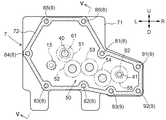
- the plurality of motor-side fasteners 8 are arranged in a state of being arranged in the circumferential direction of the motor output shaft 40 with the motor output shaft 40, which is the output shaft of the motor M, as the center in the rear view. .. Further, each of the plurality of motor-side fasteners 8 extends in the front-rear direction of the machine body and is inserted into the corresponding bolt holes from the rear.
- the distances between the motor-side fasteners 8 and the motor output shaft 40 are equal to each other. That is, the plurality of motor-side fasteners 8 are arranged on one circumference centered on the motor output shaft 40.
- the present invention is not limited to this. The distances between the motor-side fasteners 8 and the motor output shaft 40 may be different from each other.
- the tractor A includes a first fastener 81, a second fastener 82, a third fastener 83, a fourth fastener 84, a fifth fastener 85, and a sixth fastener 86.
- the first fastener 81, the second fastener 82, the third fastener 83, the fourth fastener 84, the fifth fastener 85, and the sixth fastener 86 are all motor-side fasteners 8.
- the motor M and the hydraulic pump 60 are located on one side in the front-rear direction of the machine body with respect to the first member 71. More specifically, the motor M and the hydraulic pump 60 are located on the front side with respect to the first member 71.
- the motor M has a flange FG.
- the flange FG is provided at the rear of the motor M. As shown in FIG. 6, the flange FG is formed in a hexagonal shape in the front-rear direction view.
- the flange FG is in contact with the first member 71 from the front side.
- the plurality of motor-side fasteners 8 are arranged corresponding to the six corners of the flange FG.
- the first fastener 81 is inserted into the bolt hole at the right end corner of the flange FG.
- the second fastener 82 is inserted into the bolt hole at the lower right corner of the flange FG.
- the third fastener 83 is inserted into the bolt hole at the lower left corner of the flange FG.
- the fourth fastener 84 is inserted into the bolt hole at the left end corner of the flange FG.
- the fifth fastener 85 is inserted into the bolt hole at the upper left corner of the flange FG.
- the sixth fastener 86 is inserted into the bolt hole at the upper right corner of the flange FG.
- each motor-side fastener 8 is provided in a state where the motor M, the first member 71, and the second member 72 are fastened together. With this configuration, the case 7 is connected to the motor M.
- the first member 71 supports the motor M in a cantilevered manner.
- the transmission device 50 passes between the first fastener 81 and the second fastener 82.
- the first fastener 81 and the second fastener 82 are adjacent to each other in the circumferential direction of the motor output shaft 40.
- the transmission device 50 is arranged so as to pass between the two motor-side fasteners 8 adjacent to each other in the circumferential direction of the motor output shaft 40.
- the hydraulic pump 60 is fixed to the first member 71 by a plurality of pump fixing bolts 14. With this configuration, the first member 71 supports the hydraulic pump 60 in a cantilevered manner.
- the hydraulic pump 60 is supported by the case 7. Further, the first member 71 supports the motor M in a cantilever shape and the hydraulic pump 60 in a cantilever shape.
- a plurality of pump-side fasteners 9 are arranged around the pump input shaft 41. Further, each of the plurality of pump-side fasteners 9 extends in the front-rear direction of the machine body and is inserted into the corresponding bolt holes from the rear.
- the tractor A includes a first pump side fastener 91, a second pump side fastener 92, and a third pump side fastener 93.
- the first pump-side fastener 91, the second pump-side fastener 92, and the third pump-side fastener 93 are all pump-side fasteners 9.
- the first pump side fastener 91 is located on the upper right side of the pump input shaft 41.
- the second pump-side fastener 92 is located at the lower right of the pump input shaft 41.
- the third pump-side fastener 93 is located at the lower left of the pump input shaft 41.
- oil is stored inside the case 7. Oil is also stored inside the transmission T. As shown in FIG. 6, an oil discharge portion 72a is provided below the second member 72. By removing the drain bolt in the oil discharge unit 72a during maintenance, the oil stored inside the case 7 can be discharged from the oil discharge unit 72a.
- a communication pipe 15 is connected to the lower part of the second member 72.
- the communication pipe 15 connects the second member 72 and the transmission T. Further, the communication pipe 15 communicates with the space inside the case 7. Further, the communication pipe 15 communicates with the space inside the transmission T. Therefore, the communication pipe 15 communicates the space inside the case 7 with the space inside the transmission T. As a result, the oil can move between the space inside the case 7 and the space inside the transmission T.
- the tractor A includes a first oil passage 21, a second oil passage 22, a third oil passage 23, a fourth oil passage 24, a fifth oil passage 25, and an elevating control valve 64.
- the direction in which the oil flows is indicated by an arrow.
- the first oil passage 21 connects the transmission T and the hydraulic pump 60.
- the second oil passage 22 connects the hydraulic pump 60 and the elevating control valve 64.
- the third oil passage 23 connects the hydraulic pump 60 and the power steering mechanism (not shown).
- the fourth oil passage 24 connects the elevating control valve 64 and the elevating mechanism 36.
- the fifth oil passage 25 connects the elevating control valve 64 and the transmission T.
- the hydraulic pump 60 sucks oil from the space inside the transmission T via the first oil passage 21. That is, the oil that has moved from the space inside the case 7 to the space inside the transmission T via the communication pipe 15 is supplied to the hydraulic pump 60 via the first oil passage 21.
- the oil supply path SP is composed of the communication pipe 15, the transmission T, and the first oil passage 21.
- the case 7 and the hydraulic pump 60 are connected by the oil supply path SP.
- the tractor A includes an oil supply path SP that connects the case 7 and the hydraulic pump 60. Then, the oil stored inside the case 7 passes through the oil supply path SP and is supplied to the hydraulic pump 60.
- the hydraulic pump 60 pumps the supplied oil to the second oil passage 22 and the third oil passage 23.
- the oil pumped to the second oil passage 22 is supplied to the elevating control valve 64. Further, the oil pumped to the third oil passage 23 is supplied to the power steering mechanism.
- the power steering mechanism is operated by the oil supplied through the third oil passage 23.
- the elevating control valve 64 controls the supply of oil to the elevating mechanism 36 and the discharge of oil from the elevating mechanism 36.
- the elevating mechanism 36 By supplying oil from the elevating control valve 64 to the elevating mechanism 36 via the fourth oil passage 24, the elevating mechanism 36 operates in the ascending direction. As a result, the tilling device 13 rises.
- elevating control valve 64 is configured so that oil can be returned to the transmission T via the fifth oil passage 25.
- the motor M and the case 7 are relatively close to each other. Further, the hydraulic pump 60 and the case 7 are relatively close to each other. Therefore, the motor M and the hydraulic pump 60 are relatively close to each other. Therefore, the power transmission path from the motor M to the hydraulic pump 60 becomes relatively short. As a result, the power transmission loss from the motor M to the hydraulic pump 60 is relatively small.
- the hydraulic pump 60 is supported by the case 7. Therefore, it is not necessary to provide a dedicated member for supporting the hydraulic pump 60. Therefore, the manufacturing cost tends to be lower than in the case where a dedicated member is provided to support the hydraulic pump 60.
- the first member 71 may be located on the rear side with respect to the second member 72.
- the motor M and the hydraulic pump 60 may be located on the rear side with respect to the first member 71.
- the second member 72 may be configured to be separable from the first member 71 to the front side.
- the tractor A may be equipped with an engine and configured in a hybrid manner.
- the motor M may be arranged at a position other than the position sandwiched between the left and right main frames 20.
- the motor M may be arranged above the left and right main frames 20.
- various devices such as a fertilizer spraying device, a chemical spraying device, a sowing device, and a harvesting device, and a working device such as a loader and an excavator may be provided.
- various devices such as a fertilizer spraying device, a chemical spraying device, a sowing device, and a harvesting device, and a working device such as a loader and an excavator correspond to the "working device" according to the present invention.
- the support structure of the hydraulic pump 60 does not have to be cantilevered.
- Case 7 may be composed of a single member.
- the motor M is supported by the case 7.
- the present invention is not limited to this, and the case 7 may be supported by the motor M.
- the number of motor-side fasteners 8 provided is six.
- the present invention is not limited to this, and the number of motor-side fasteners 8 provided may be any number other than six.
- the number of pump-side fasteners 9 provided is three.
- the present invention is not limited to this, and the number of pump-side fasteners 9 provided may be any number other than three.
- the present invention can be used not only for tractors but also for various electric work platforms such as combine harvesters, rice transplanters, and construction work machines.
- Motor side fastener 10 Front wheels (traveling device) 11 Rear wheel (traveling device) 13 Tillage equipment (working equipment) 20 Main frame 36 Elevating mechanism (operating mechanism) 40 Motor output shaft 50 Transmission device 60 Hydraulic pump 71 First member 72 Second member A Tractor (electric work platform) M motor SP oil supply path
Landscapes
- Engineering & Computer Science (AREA)
- Chemical & Material Sciences (AREA)
- Combustion & Propulsion (AREA)
- Transportation (AREA)
- Mechanical Engineering (AREA)
- Motor Power Transmission Devices (AREA)
- Arrangement Or Mounting Of Propulsion Units For Vehicles (AREA)
- Auxiliary Drives, Propulsion Controls, And Safety Devices (AREA)
Abstract
La présente invention concerne un véhicule de travail électrique comprenant : un dispositif de travail ; une batterie ; un moteur (M) qui est actionné par l'énergie électrique approvisionnée par la batterie ; un dispositif de déplacement qui est entraîné par le moteur (M) ; une pompe hydraulique (60) qui est entraînée par le moteur (M) et qui approvisionne en huile un mécanisme de fonctionnement du dispositif de travail ; un dispositif de transmission qui transmet de l'énergie du moteur (M) à la pompe hydraulique (60) ; et un boîtier (7) qui contient le dispositif de transmission. Le boîtier (7) est accouplé au moteur (7). La pompe hydraulique (60) est maintenue par le boîtier (7).
Priority Applications (3)
| Application Number | Priority Date | Filing Date | Title |
|---|---|---|---|
| US17/783,424 US12179586B2 (en) | 2019-12-26 | 2020-10-14 | Electric work vehicle |
| EP20908109.0A EP4082821A4 (fr) | 2019-12-26 | 2020-10-14 | Véhicule de travail électrique |
| US18/911,585 US12370888B2 (en) | 2019-12-26 | 2024-10-10 | Electric work vehicle |
Applications Claiming Priority (2)
| Application Number | Priority Date | Filing Date | Title |
|---|---|---|---|
| JP2019-237394 | 2019-12-26 | ||
| JP2019237394A JP7206182B2 (ja) | 2019-12-26 | 2019-12-26 | 電動作業車 |
Related Child Applications (2)
| Application Number | Title | Priority Date | Filing Date |
|---|---|---|---|
| US17/783,424 A-371-Of-International US12179586B2 (en) | 2019-12-26 | 2020-10-14 | Electric work vehicle |
| US18/911,585 Continuation US12370888B2 (en) | 2019-12-26 | 2024-10-10 | Electric work vehicle |
Publications (1)
| Publication Number | Publication Date |
|---|---|
| WO2021131249A1 true WO2021131249A1 (fr) | 2021-07-01 |
Family
ID=76574253
Family Applications (1)
| Application Number | Title | Priority Date | Filing Date |
|---|---|---|---|
| PCT/JP2020/038691 Ceased WO2021131249A1 (fr) | 2019-12-26 | 2020-10-14 | Véhicule de travail électrique |
Country Status (4)
| Country | Link |
|---|---|
| US (2) | US12179586B2 (fr) |
| EP (1) | EP4082821A4 (fr) |
| JP (3) | JP7206182B2 (fr) |
| WO (1) | WO2021131249A1 (fr) |
Cited By (3)
| Publication number | Priority date | Publication date | Assignee | Title |
|---|---|---|---|---|
| US11472288B2 (en) * | 2017-11-10 | 2022-10-18 | Syn Trac Gmbh | Vehicle-side and accessory-side power take-off shaft connecting device and power take-off shaft connecting unit comprising the two power take-off shaft connecting devices |
| EP4342704A1 (fr) * | 2022-09-26 | 2024-03-27 | Kubota Corporation | Véhicule de travail |
| WO2025142149A1 (fr) * | 2023-12-27 | 2025-07-03 | 株式会社クボタ | Tracteur électrique |
Families Citing this family (12)
| Publication number | Priority date | Publication date | Assignee | Title |
|---|---|---|---|---|
| JP7206182B2 (ja) * | 2019-12-26 | 2023-01-17 | 株式会社クボタ | 電動作業車 |
| JP7499737B2 (ja) * | 2021-06-29 | 2024-06-14 | 株式会社クボタ | 電動作業車 |
| WO2023119929A1 (fr) * | 2021-12-24 | 2023-06-29 | 株式会社クボタ | Véhicule de travail électrique |
| JP7565909B2 (ja) * | 2021-12-24 | 2024-10-11 | 株式会社クボタ | 電動作業車 |
| JP7745457B2 (ja) * | 2021-12-24 | 2025-09-29 | 株式会社クボタ | 電動作業車 |
| JP7829338B2 (ja) * | 2022-01-28 | 2026-03-13 | 株式会社クボタ | 電動作業車 |
| JP7795967B2 (ja) * | 2022-05-10 | 2026-01-08 | ヤンマーホールディングス株式会社 | 作業車両 |
| US12319138B2 (en) | 2022-11-30 | 2025-06-03 | Parker-Hannifin Corporation | Integrated electric power take-off for use with an electric vehicle |
| JP7770300B2 (ja) * | 2022-12-27 | 2025-11-14 | 株式会社クボタ | 電動作業車 |
| JP2024157830A (ja) | 2023-04-26 | 2024-11-08 | 株式会社クボタ | 電動モータパワートレイン、及び多目的車両 |
| WO2025004527A1 (fr) * | 2023-06-30 | 2025-01-02 | 株式会社クボタ | Engin de travail |
| WO2025142303A1 (fr) * | 2023-12-27 | 2025-07-03 | 株式会社クボタ | Tracteur électrique |
Citations (7)
| Publication number | Priority date | Publication date | Assignee | Title |
|---|---|---|---|---|
| JPH0586770A (ja) * | 1991-09-26 | 1993-04-06 | Omron Corp | 店舗用ゲートシステム |
| US20060059879A1 (en) * | 2004-09-20 | 2006-03-23 | Edmond Brian W | Multifunction electric tractor |
| JP2012056446A (ja) * | 2010-09-09 | 2012-03-22 | Yanmar Co Ltd | 作業車両 |
| JP2013034439A (ja) * | 2011-08-09 | 2013-02-21 | Mitsubishi Agricultural Machinery Co Ltd | 乗用田植機 |
| JP2013066290A (ja) * | 2011-09-16 | 2013-04-11 | Kubota Corp | 作業車 |
| JP2013248918A (ja) * | 2012-05-30 | 2013-12-12 | Iseki & Co Ltd | 電動作業車両 |
| JP2018069926A (ja) | 2016-10-28 | 2018-05-10 | 株式会社クボタ | トラクター |
Family Cites Families (114)
| Publication number | Priority date | Publication date | Assignee | Title |
|---|---|---|---|---|
| US1055619A (en) * | 1912-04-27 | 1913-03-11 | William Dunn | Hydraulic transmission mechanism. |
| US1609833A (en) * | 1921-12-12 | 1926-12-07 | Universal Engineering Corp | Locomotive engine |
| US4233858A (en) * | 1976-12-27 | 1980-11-18 | The Garrett Corporation | Flywheel drive system having a split electromechanical transmission |
| JPS6325421Y2 (fr) * | 1980-04-03 | 1988-07-11 | ||
| JP2538356B2 (ja) * | 1989-11-20 | 1996-09-25 | 株式会社神崎高級工機製作所 | 自走式作業車のトランスミツシヨン装置 |
| US5046306A (en) * | 1990-07-23 | 1991-09-10 | General Motors Corporation | Secondary oil system |
| JP2585281Y2 (ja) * | 1992-04-30 | 1998-11-18 | 三菱農機株式会社 | 電動農用トラクタ |
| JP3445339B2 (ja) * | 1993-11-25 | 2003-09-08 | 株式会社 神崎高級工機製作所 | 作業車用四輪駆動トランスミッション |
| US5406778A (en) * | 1994-02-03 | 1995-04-18 | Ransomes America Corporation | Electric drive riding greens mower |
| JP3445391B2 (ja) * | 1994-11-11 | 2003-09-08 | 株式会社 神崎高級工機製作所 | トラクタのトランスミッション装置 |
| US5557977A (en) * | 1995-11-06 | 1996-09-24 | Ford Motor Company | System for powering rotating vehicle accessories using transmission |
| US6048288A (en) * | 1997-11-18 | 2000-04-11 | Toyota Jidosha Kabushiki Kaisha | Power train system for a vehicle and method for operating same |
| US6109009A (en) * | 1998-01-16 | 2000-08-29 | Textron Inc. | Constant speed control for electric greens mower |
| CA2328858A1 (fr) * | 1998-04-17 | 1999-10-28 | Tract-A-Pillar Tractor Co., Inc. | Vehicule terrestre |
| EP1350421B1 (fr) * | 2002-04-03 | 2006-06-07 | Kanzaki Kokyukoki MFG. Co., Ltd. | Pompe et véhicule de travail |
| US6860358B1 (en) * | 2002-10-04 | 2005-03-01 | Hydro-Gear Limited Partnership | Utility vehicle having hydrostatic drive |
| US6953327B1 (en) * | 2003-03-11 | 2005-10-11 | Hydro-Gear Limited Partnership | Dual pump |
| DE10318070C5 (de) * | 2003-04-17 | 2022-06-23 | Volkswagen Ag | Vorrichtung und Verfahren zur Schmierung und Kühlung von Zahnradgetrieben |
| US6964631B2 (en) * | 2004-02-24 | 2005-11-15 | General Motors Corporation | Integrated electric motor-driven oil pump for automatic transmissions in hybrid applications |
| US7421917B2 (en) * | 2004-06-25 | 2008-09-09 | Kubota Corporation | Tractor with a PTO apparatus |
| JP2006321339A (ja) * | 2005-05-18 | 2006-11-30 | Kanzaki Kokyukoki Mfg Co Ltd | 油圧駆動式作業車両の動力伝達機構 |
| JP2007189912A (ja) * | 2006-01-17 | 2007-08-02 | Kubota Corp | 農作業車 |
| JP2008157161A (ja) * | 2006-12-26 | 2008-07-10 | Kanzaki Kokyukoki Mfg Co Ltd | マルチポンプユニットおよびマルチポンプユニット付車両 |
| JP4311754B2 (ja) * | 2007-06-21 | 2009-08-12 | 三菱電機株式会社 | 車両用駆動装置 |
| US7713157B2 (en) * | 2007-07-11 | 2010-05-11 | Eaton Corporation | Planetary gear controlled alternator |
| US7726275B2 (en) * | 2007-07-12 | 2010-06-01 | Ford Global Technologies, Llc | System and method for powering a mechanically driven accessory component in an automotive vehicle |
| US9878616B2 (en) * | 2007-07-12 | 2018-01-30 | Power Technology Holdings Llc | Hybrid vehicle drive system and method using split shaft power take off |
| US8808124B2 (en) * | 2008-04-15 | 2014-08-19 | GM Global Technology Operations LLC | Belt alternator starter systems for hybrid vehicles |
| JP4707072B2 (ja) * | 2008-05-23 | 2011-06-22 | 本田技研工業株式会社 | 車両用動力伝達装置 |
| US8055399B2 (en) * | 2008-10-23 | 2011-11-08 | Hydro-Gear Limited Partnership | Control systems and methods for electric motors of utility vehicles |
| US8511216B2 (en) * | 2009-03-30 | 2013-08-20 | Kanzaki Kokyukoki Mfg. Co., Ltd. | Hydraulic actuator unit |
| KR20100133062A (ko) * | 2009-06-11 | 2010-12-21 | 이한기 | 건설기계의 동력전달장치 |
| WO2011036959A1 (fr) * | 2009-09-25 | 2011-03-31 | アイシン・エィ・ダブリュ株式会社 | Dispositif de transmission |
| CN102666169A (zh) * | 2010-01-18 | 2012-09-12 | 日立建机株式会社 | 作业用车辆的驱动控制装置 |
| US20110190083A1 (en) * | 2010-02-02 | 2011-08-04 | ALTe | Accessory drive system for a vehicle |
| JP5168598B2 (ja) * | 2010-03-31 | 2013-03-21 | アイシン・エィ・ダブリュ株式会社 | ハイブリッド駆動装置 |
| JP5365880B2 (ja) * | 2010-06-08 | 2013-12-11 | アイシン・エィ・ダブリュ株式会社 | 車両用駆動装置 |
| US8649925B2 (en) * | 2010-08-30 | 2014-02-11 | Ford Global Technologies, Llc | Method and system for controlling operation of an electric oil pump in a hybrid electric vehicle (HEV) |
| US8689759B2 (en) * | 2010-10-01 | 2014-04-08 | GM Global Technology Operations LLC | Dual drive pump system using an engine starter motor |
| JP2012117349A (ja) * | 2010-12-03 | 2012-06-21 | Yanmar Co Ltd | 油圧ショベルの動力伝達装置 |
| US8616310B2 (en) * | 2011-01-14 | 2013-12-31 | Gilbert T. Lopez | Apparatus for farming, gardening and landscaping |
| US8905885B2 (en) * | 2011-02-04 | 2014-12-09 | Aisin Aw Co., Ltd. | Vehicle drive device |
| JP5297473B2 (ja) * | 2011-02-04 | 2013-09-25 | アイシン・エィ・ダブリュ株式会社 | 車両用駆動装置 |
| JP2012202066A (ja) * | 2011-03-24 | 2012-10-22 | Komatsu Ltd | 電動式作業車両及びその電源ユニット |
| CN103109112B (zh) * | 2011-04-13 | 2015-10-14 | 日产自动车株式会社 | 车辆用轮内马达单元的润滑控制装置 |
| CA2838592C (fr) * | 2011-06-07 | 2016-10-25 | Honda Motor Co., Ltd. | Dispositif d'entrainement de vehicule |
| WO2013009324A1 (fr) * | 2011-07-14 | 2013-01-17 | Husqvarna Ab | Tondeuse à gazon autoportée comprenant un système de coupe alimenté par batterie |
| WO2013011562A1 (fr) * | 2011-07-19 | 2013-01-24 | トヨタ自動車株式会社 | Dispositif de lubrification de dispositif de transmission de puissance pour véhicule hybride |
| JP2013053737A (ja) * | 2011-09-06 | 2013-03-21 | Honda Motor Co Ltd | 遊星歯車機構の支持構造 |
| JP5699227B2 (ja) * | 2011-12-01 | 2015-04-08 | 本田技研工業株式会社 | 動力伝達装置 |
| US8784246B2 (en) * | 2011-12-14 | 2014-07-22 | Caterpillar Inc. | Series drivetrain with CVT output |
| WO2013093986A1 (fr) * | 2011-12-24 | 2013-06-27 | 川崎重工業株式会社 | Véhicule à propulsion électrique |
| JP5885534B2 (ja) * | 2012-02-21 | 2016-03-15 | 本田技研工業株式会社 | 制御システム |
| EP2639128B1 (fr) * | 2012-03-13 | 2023-09-06 | Kanzaki Kokyukoki Mfg. Co., Ltd. | Véhicule de travail |
| JP2015514624A (ja) * | 2012-03-29 | 2015-05-21 | イートン コーポレーションEaton Corporation | 可変速度式ハイブリッド電気スーパーチャージャーアセンブリを用いた電気エネルギの生成 |
| US9500197B2 (en) * | 2012-05-18 | 2016-11-22 | Gm Global Technology Operations, Llc | Pump assembly with multiple gear ratios |
| DE102013013623B4 (de) * | 2012-08-29 | 2022-06-30 | Kanzaki Kokyukoki Mfg. Co., Ltd. | Motorsteuersystem für ein mit elektrischem Motor angetriebenes Fahrzeug |
| JP6192919B2 (ja) * | 2012-11-02 | 2017-09-06 | Ntn株式会社 | インホイールモータ駆動装置 |
| US9033074B1 (en) * | 2012-11-19 | 2015-05-19 | Chris Gates | Coupler with movable shaft |
| JP5790630B2 (ja) * | 2012-12-05 | 2015-10-07 | トヨタ自動車株式会社 | 潤滑油供給構造 |
| JP5741563B2 (ja) * | 2012-12-06 | 2015-07-01 | トヨタ自動車株式会社 | 動力伝達装置 |
| US9114798B1 (en) * | 2012-12-12 | 2015-08-25 | Hydro-Gear Limited Partnership | Electric actuator for drive apparatus |
| US8939240B2 (en) * | 2013-03-01 | 2015-01-27 | Paccar Inc | Engine accessory drive system |
| US9487086B2 (en) * | 2013-04-02 | 2016-11-08 | Parker-Hannifin Corporation | Auxiliary modules mounted on a vehicle |
| SE538232C2 (sv) * | 2013-05-08 | 2016-04-12 | BAE Systems Hägglunds Aktiebolag | Drivenhet för bandgående fordon och fordon försett med drivenhet |
| SE540219C2 (sv) * | 2013-05-21 | 2018-05-02 | Scania Cv Ab | Kraftuttag, fordon med ett sådant kraftuttag och ett mellanstycke för ett sådant kraftuttag |
| FR3008038B1 (fr) * | 2013-07-02 | 2016-12-02 | Technoboost | Groupe motopropulseur pour un vehicule hybride hydraulique, comprenant une machine electrique |
| JP5705928B2 (ja) * | 2013-08-08 | 2015-04-22 | 株式会社小松製作所 | ホイールローダ |
| JP6182438B2 (ja) * | 2013-11-26 | 2017-08-16 | アイシン・エィ・ダブリュ株式会社 | 車両用駆動伝達装置 |
| DE102013017976A1 (de) * | 2013-11-29 | 2015-06-03 | Fte Automotive Gmbh | Elektromotorisch angetriebene Flüssigkeitspumpe, insbesondere zur Zwangsschmierung eines Schaltgetriebes für Kraftfahrzeuge |
| MY188847A (en) * | 2013-12-02 | 2022-01-09 | Honda Motor Co Ltd | Vehicle |
| JP6364194B2 (ja) * | 2014-01-29 | 2018-07-25 | 株式会社小松製作所 | 作業車両及びその制御方法 |
| GB2523765B (en) * | 2014-03-04 | 2016-09-28 | Johnston Sweepers Ltd | Powertrain for a road cleaning vehicle |
| MY167373A (en) * | 2014-06-10 | 2018-08-16 | Honda Motor Co Ltd | Power plant |
| US9156348B1 (en) * | 2014-07-17 | 2015-10-13 | GM Global Technology Operations LLC | Two axis electric drive |
| US9145054B1 (en) * | 2014-10-20 | 2015-09-29 | Power Solutions International, Inc. | Modular power take-off assembly |
| US20160145833A1 (en) * | 2014-11-21 | 2016-05-26 | Caterpillar Global Mining Llc | System and method for controlling power in machine having hydraulic devices |
| JP2016130115A (ja) * | 2015-01-15 | 2016-07-21 | トヨタ自動車株式会社 | ハイブリッド車の駆動制御装置 |
| JP6396841B2 (ja) * | 2015-04-21 | 2018-09-26 | 株式会社クボタ | トラクタに備えられる伝動装置 |
| JP6914247B2 (ja) * | 2015-05-01 | 2021-08-04 | ブラックバーン エナジー インコーポレイテッド | 補助発電のための方法およびシステム |
| US10106027B1 (en) * | 2015-06-01 | 2018-10-23 | Hydro-Gear Limited Partnership | Generator/cooling assembly and system for utility vehicle |
| US10358040B1 (en) * | 2015-06-01 | 2019-07-23 | Hydro-Gear Limited Partnership | Drive assembly and system for utility vehicle |
| US10563761B2 (en) * | 2015-08-07 | 2020-02-18 | Yanmar Co., Ltd. | Work vehicle |
| JP6572465B2 (ja) | 2015-09-30 | 2019-09-11 | ジヤトコ株式会社 | パワートレーン |
| JP6314947B2 (ja) * | 2015-10-02 | 2018-04-25 | トヨタ自動車株式会社 | 動力伝達装置の冷却構造 |
| CN107303814A (zh) | 2016-04-18 | 2017-10-31 | 深圳市沃特玛电池有限公司 | 一种电动车动力轮系总成 |
| JP6172354B2 (ja) | 2016-07-19 | 2017-08-02 | 井関農機株式会社 | トラクタ |
| JP6696857B2 (ja) * | 2016-08-12 | 2020-05-20 | トヨタ自動車株式会社 | 車両用歯車装置の潤滑装置 |
| US10099552B2 (en) * | 2016-09-30 | 2018-10-16 | Deere & Company | Hydraulic-electric drive arrangement for work vehicles |
| JP6477656B2 (ja) * | 2016-10-14 | 2019-03-06 | トヨタ自動車株式会社 | 動力伝達装置の油路構造 |
| JP6423403B2 (ja) * | 2016-10-14 | 2018-11-14 | トヨタ自動車株式会社 | 動力伝達装置の油路構造 |
| JP6545217B2 (ja) * | 2017-03-24 | 2019-07-17 | 本田技研工業株式会社 | 動力伝達装置の潤滑流体供給構造 |
| JP6680263B2 (ja) * | 2017-05-19 | 2020-04-15 | トヨタ自動車株式会社 | ハイブリッド車両の駆動装置 |
| JP6809393B2 (ja) * | 2017-06-20 | 2021-01-06 | トヨタ自動車株式会社 | 車両用動力伝達装置の潤滑装置 |
| JP6338003B1 (ja) * | 2017-09-27 | 2018-06-06 | トヨタ自動車株式会社 | 電気自動車 |
| CN110739804B (zh) * | 2018-07-18 | 2022-04-12 | 株式会社爱信 | 旋转电机的冷却构造和车辆用驱动装置 |
| JP7107565B2 (ja) * | 2018-10-22 | 2022-07-27 | 株式会社 神崎高級工機製作所 | 移動体駆動ユニット及び移動体 |
| JP6996474B2 (ja) * | 2018-10-31 | 2022-01-17 | トヨタ自動車株式会社 | 動力伝達装置の潤滑装置 |
| US10948070B2 (en) * | 2018-11-13 | 2021-03-16 | Deere & Company | Electric machine lubrication system |
| JP7052746B2 (ja) * | 2019-01-25 | 2022-04-12 | トヨタ自動車株式会社 | 車両用動力伝達装置 |
| JP7111006B2 (ja) * | 2019-01-25 | 2022-08-02 | トヨタ自動車株式会社 | 車両用動力伝達装置 |
| US11084369B2 (en) * | 2019-02-26 | 2021-08-10 | Deere & Company | Hybrid transmission module for work vehicles |
| JP7172762B2 (ja) * | 2019-03-13 | 2022-11-16 | トヨタ自動車株式会社 | 車両用油供給装置の制御装置 |
| US10690234B1 (en) * | 2019-03-14 | 2020-06-23 | Proterra Inc. | Electric vehicle powertrain |
| JP7151632B2 (ja) * | 2019-06-11 | 2022-10-12 | トヨタ自動車株式会社 | ハイブリッド車両 |
| JP7323349B2 (ja) | 2019-06-24 | 2023-08-08 | 株式会社クボタ | 電動作業車 |
| JP7246264B2 (ja) * | 2019-06-24 | 2023-03-27 | 株式会社クボタ | 電動作業車 |
| JP7321008B2 (ja) | 2019-06-24 | 2023-08-04 | 株式会社クボタ | 電動作業車 |
| JP7224245B2 (ja) * | 2019-06-24 | 2023-02-17 | 株式会社クボタ | 電動作業車 |
| US10989297B2 (en) * | 2019-07-19 | 2021-04-27 | Ford Global Technologies, Llc | Electric powertrain with sun bearing |
| US10981024B1 (en) * | 2019-10-11 | 2021-04-20 | Oshkosh Corporation | Hybrid fire fighting vehicle |
| JP7206182B2 (ja) * | 2019-12-26 | 2023-01-17 | 株式会社クボタ | 電動作業車 |
| JP7671157B2 (ja) * | 2021-03-08 | 2025-05-01 | ニデック株式会社 | 駆動装置 |
| US11754169B1 (en) * | 2022-07-07 | 2023-09-12 | Ford Global Technologies, Llc | Lubrication and cooling oil distribution system for a vehicle transaxle |
-
2019
- 2019-12-26 JP JP2019237394A patent/JP7206182B2/ja active Active
-
2020
- 2020-10-14 WO PCT/JP2020/038691 patent/WO2021131249A1/fr not_active Ceased
- 2020-10-14 US US17/783,424 patent/US12179586B2/en active Active
- 2020-10-14 EP EP20908109.0A patent/EP4082821A4/fr active Pending
-
2023
- 2023-01-04 JP JP2023000110A patent/JP7425900B2/ja active Active
-
2024
- 2024-01-18 JP JP2024005905A patent/JP7672523B2/ja active Active
- 2024-10-10 US US18/911,585 patent/US12370888B2/en active Active
Patent Citations (7)
| Publication number | Priority date | Publication date | Assignee | Title |
|---|---|---|---|---|
| JPH0586770A (ja) * | 1991-09-26 | 1993-04-06 | Omron Corp | 店舗用ゲートシステム |
| US20060059879A1 (en) * | 2004-09-20 | 2006-03-23 | Edmond Brian W | Multifunction electric tractor |
| JP2012056446A (ja) * | 2010-09-09 | 2012-03-22 | Yanmar Co Ltd | 作業車両 |
| JP2013034439A (ja) * | 2011-08-09 | 2013-02-21 | Mitsubishi Agricultural Machinery Co Ltd | 乗用田植機 |
| JP2013066290A (ja) * | 2011-09-16 | 2013-04-11 | Kubota Corp | 作業車 |
| JP2013248918A (ja) * | 2012-05-30 | 2013-12-12 | Iseki & Co Ltd | 電動作業車両 |
| JP2018069926A (ja) | 2016-10-28 | 2018-05-10 | 株式会社クボタ | トラクター |
Non-Patent Citations (1)
| Title |
|---|
| See also references of EP4082821A4 |
Cited By (4)
| Publication number | Priority date | Publication date | Assignee | Title |
|---|---|---|---|---|
| US11472288B2 (en) * | 2017-11-10 | 2022-10-18 | Syn Trac Gmbh | Vehicle-side and accessory-side power take-off shaft connecting device and power take-off shaft connecting unit comprising the two power take-off shaft connecting devices |
| EP4342704A1 (fr) * | 2022-09-26 | 2024-03-27 | Kubota Corporation | Véhicule de travail |
| US12139026B2 (en) | 2022-09-26 | 2024-11-12 | Kubota Corporation | Work vehicle |
| WO2025142149A1 (fr) * | 2023-12-27 | 2025-07-03 | 株式会社クボタ | Tracteur électrique |
Also Published As
| Publication number | Publication date |
|---|---|
| US12370888B2 (en) | 2025-07-29 |
| JP2023026578A (ja) | 2023-02-24 |
| JP7425900B2 (ja) | 2024-01-31 |
| JP2021104768A (ja) | 2021-07-26 |
| US20230010534A1 (en) | 2023-01-12 |
| JP7206182B2 (ja) | 2023-01-17 |
| US12179586B2 (en) | 2024-12-31 |
| EP4082821A4 (fr) | 2024-01-03 |
| JP2024032808A (ja) | 2024-03-12 |
| US20250033466A1 (en) | 2025-01-30 |
| JP7672523B2 (ja) | 2025-05-07 |
| EP4082821A1 (fr) | 2022-11-02 |
Similar Documents
| Publication | Publication Date | Title |
|---|---|---|
| JP7206182B2 (ja) | 電動作業車 | |
| JP2023026578A5 (fr) | ||
| JP7323349B2 (ja) | 電動作業車 | |
| JP7246264B2 (ja) | 電動作業車 | |
| CN113840750A (zh) | 电动作业车辆 | |
| JP7321008B2 (ja) | 電動作業車 | |
| CN103569205B (zh) | 一种作业车的车身结构 | |
| US12139026B2 (en) | Work vehicle | |
| US12565093B2 (en) | Inverter arrangement for an electric work vehicle | |
| US12377735B2 (en) | Work vehicle | |
| JP2002337757A (ja) | クローラ式作業機 | |
| WO2023127229A1 (fr) | Engin électrique de chantier | |
| JP4694717B2 (ja) | クローラ式作業機 | |
| WO2003000032A1 (fr) | Machine agricole | |
| JP4627922B2 (ja) | クローラ式作業機 | |
| JP4718045B2 (ja) | 農作業機 | |
| WO2025142247A1 (fr) | Tracteur électrique | |
| JP2002347661A (ja) | クローラ式作業機 | |
| JP4160327B2 (ja) | 自走式作業機 | |
| JP2022101316A (ja) | 作業車 | |
| JPH0459436A (ja) | トラクタの油圧ポンプ取付装置 | |
| JP2002337761A (ja) | クローラ式作業機 |
Legal Events
| Date | Code | Title | Description |
|---|---|---|---|
| 121 | Ep: the epo has been informed by wipo that ep was designated in this application |
Ref document number: 20908109 Country of ref document: EP Kind code of ref document: A1 |
|
| NENP | Non-entry into the national phase |
Ref country code: DE |
|
| ENP | Entry into the national phase |
Ref document number: 2020908109 Country of ref document: EP Effective date: 20220726 |