WO2021144882A1 - Système de commande de laminage et procédé de commande de laminage - Google Patents
Système de commande de laminage et procédé de commande de laminage Download PDFInfo
- Publication number
- WO2021144882A1 WO2021144882A1 PCT/JP2020/001065 JP2020001065W WO2021144882A1 WO 2021144882 A1 WO2021144882 A1 WO 2021144882A1 JP 2020001065 W JP2020001065 W JP 2020001065W WO 2021144882 A1 WO2021144882 A1 WO 2021144882A1
- Authority
- WO
- WIPO (PCT)
- Prior art keywords
- control
- speed
- rolling
- roll gap
- plate thickness
- Prior art date
- Legal status (The legal status is an assumption and is not a legal conclusion. Google has not performed a legal analysis and makes no representation as to the accuracy of the status listed.)
- Ceased
Links
Images


Classifications
-
- B—PERFORMING OPERATIONS; TRANSPORTING
- B21—MECHANICAL METAL-WORKING WITHOUT ESSENTIALLY REMOVING MATERIAL; PUNCHING METAL
- B21B—ROLLING OF METAL
- B21B37/00—Control devices or methods specially adapted for metal-rolling mills or the work produced thereby
- B21B37/16—Control of thickness, width, diameter or other transverse dimensions
-
- B—PERFORMING OPERATIONS; TRANSPORTING
- B21—MECHANICAL METAL-WORKING WITHOUT ESSENTIALLY REMOVING MATERIAL; PUNCHING METAL
- B21B—ROLLING OF METAL
- B21B37/00—Control devices or methods specially adapted for metal-rolling mills or the work produced thereby
- B21B37/48—Tension control; Compression control
-
- B—PERFORMING OPERATIONS; TRANSPORTING
- B21—MECHANICAL METAL-WORKING WITHOUT ESSENTIALLY REMOVING MATERIAL; PUNCHING METAL
- B21B—ROLLING OF METAL
- B21B37/00—Control devices or methods specially adapted for metal-rolling mills or the work produced thereby
- B21B37/28—Control of flatness or profile during rolling of strip, sheets or plates
-
- B—PERFORMING OPERATIONS; TRANSPORTING
- B21—MECHANICAL METAL-WORKING WITHOUT ESSENTIALLY REMOVING MATERIAL; PUNCHING METAL
- B21B—ROLLING OF METAL
- B21B2261/00—Product parameters
- B21B2261/02—Transverse dimensions
- B21B2261/04—Thickness, gauge
-
- B—PERFORMING OPERATIONS; TRANSPORTING
- B21—MECHANICAL METAL-WORKING WITHOUT ESSENTIALLY REMOVING MATERIAL; PUNCHING METAL
- B21B—ROLLING OF METAL
- B21B2271/00—Mill stand parameters
- B21B2271/02—Roll gap, screw-down position, draft position
-
- B—PERFORMING OPERATIONS; TRANSPORTING
- B21—MECHANICAL METAL-WORKING WITHOUT ESSENTIALLY REMOVING MATERIAL; PUNCHING METAL
- B21B—ROLLING OF METAL
- B21B2275/00—Mill drive parameters
- B21B2275/02—Speed
- B21B2275/06—Product speed
-
- B—PERFORMING OPERATIONS; TRANSPORTING
- B21—MECHANICAL METAL-WORKING WITHOUT ESSENTIALLY REMOVING MATERIAL; PUNCHING METAL
- B21B—ROLLING OF METAL
- B21B37/00—Control devices or methods specially adapted for metal-rolling mills or the work produced thereby
- B21B37/16—Control of thickness, width, diameter or other transverse dimensions
- B21B37/18—Automatic gauge control
- B21B37/20—Automatic gauge control in tandem mills
-
- B—PERFORMING OPERATIONS; TRANSPORTING
- B21—MECHANICAL METAL-WORKING WITHOUT ESSENTIALLY REMOVING MATERIAL; PUNCHING METAL
- B21B—ROLLING OF METAL
- B21B37/00—Control devices or methods specially adapted for metal-rolling mills or the work produced thereby
- B21B37/46—Roll speed or drive motor control
-
- B—PERFORMING OPERATIONS; TRANSPORTING
- B21—MECHANICAL METAL-WORKING WITHOUT ESSENTIALLY REMOVING MATERIAL; PUNCHING METAL
- B21B—ROLLING OF METAL
- B21B37/00—Control devices or methods specially adapted for metal-rolling mills or the work produced thereby
- B21B37/58—Roll-force control; Roll-gap control
Definitions
- the present invention relates to a rolling control system and a rolling control method.
- Japanese Patent Application Laid-Open No. 2016-93828 discloses a rolling control system in which AGC and ATR can be switched according to the rolling speed of the material to be rolled.
- This conventional system selects the first control method when the rolling speed is slow and the second control method when the rolling speed is high.
- the ATR in which the speed of the material to be rolled is controlled so that the inlet tension of the rolling mill becomes the target value
- the roll gap of the rolling mill is controlled so that the outer plate thickness becomes the target value.
- AGC and In the second control method an ATR in which the roll gap is controlled so that the inlet tension becomes a target value and an AGC in which the speed of the material to be rolled is controlled so that the outlet plate thickness becomes a target value are used.
- the deviation between the entry side tension and the target value in the ATR before switching is adjusted. Specifically, when the entry side tension deviation is within a predetermined range, the entry side tension deviation is changed to zero. If the entry-side tension deviation is outside the predetermined range, the entry-side tension deviation is changed to a value obtained by subtracting a predetermined value from the entry-side tension deviation. As a result, it is possible to prevent the AGC control amount after switching from becoming excessive as compared with the case where the entry side tension deviation is not adjusted.
- the entry-side tension deviation is adjusted when the control method is switched as the rolling speed increases.
- the adjusted entry-side tension deviation will be used in the calculation of the controlled amount of AGC after switching. Therefore, when the on-side tension deviation immediately before switching greatly deviates from the predetermined range, the control amount of AGC after switching may violate the upper limit constraint. Then, there is a possibility that the continuation of AGC after switching may be hindered.
- the present invention has been made to solve the above-mentioned problems, and avoids a situation in which it becomes difficult to continue AGC after switching when switching from ATR to AGC is performed as the rolling speed increases.
- the purpose is to provide a technology that can be used.
- the first invention is a rolling control system for achieving the above-mentioned object, and has the following features.
- the rolling control system includes a rolling stand and a rolling control device.
- the rolling control device performs speed control in which the speed of the material to be rolled on the entry side of the rolling stand is a control operation end and roll gap control in which the roll gap of the rolling stand is the control operation end.
- the rolling control device includes a first plate thickness control unit, a second plate thickness control unit, a first tension control unit, a second tension control unit, and a control selection unit.
- the first plate thickness control unit performs roll gap-plate thickness control, which is the roll gap control for controlling the plate thickness of the material to be rolled on the outlet side of the rolling stand.
- the second plate thickness control unit performs speed-plate thickness control, which is the speed control for controlling the plate thickness.
- the first tension control unit performs speed-tension control, which is the speed control for controlling the tension of the material to be rolled on the entrance side of the rolling stand.
- the second tension control unit performs roll gap-tension control, which is the roll gap control for controlling the tension.
- the control selection unit selects the speed-tension control and the roll gap-plate thickness control when the rolling speed is less than the boundary value, and the roll gap-tension control and the roll gap-tension control when the rolling speed is equal to or more than the boundary value. Select the speed-plate thickness control.
- control selection unit further calculates the speed at the time of crossing the boundary of the rolling speed-the speed controlled amount in the plate thickness control-the speed before the boundary-.
- the speed correction amount is set to zero and output to the second speed control unit so that the speed correction amount in the tension control is not reflected.
- the second invention further has the following features in the first invention. Further, when the rolling speed increases beyond the boundary value, the control selection unit reflects the speed correction amount in the calculation of the roll gap control amount in the roll gap-tension control at the time of crossing the boundary. In addition, the roll gap correction amount corresponding to the speed correction amount is calculated and output to the second roll gap control unit.
- the third invention is a rolling control method for achieving the above-mentioned object, and has the following features.
- the rolling control method is a method of performing speed control with the rolling speed as the control operation end and roll gap control with the roll gap of the rolling stand as the control operation end.
- the roll gap control includes roll gap-plate thickness control and roll gap-tension control.
- the roll gap-plate thickness control is the roll gap control for controlling the plate thickness of the material to be rolled on the outlet side of the rolling stand.
- the roll gap-tension control is the speed control for controlling the tension of the material to be rolled on the entrance side of the rolling stand.
- the speed control includes speed-tension control and speed-plate thickness control.
- the speed-tension control is the speed control for controlling the tension.
- the speed-plate thickness control is the speed control for controlling the plate thickness.
- the rolling control method further When the rolling speed of the material to be rolled is less than the boundary value, the speed-tension control and the roll gap-plate thickness control are selected. When the rolling speed is equal to or higher than the boundary value, the roll gap-tension control and the speed-plate thickness control are selected. When the rolling speed increases beyond the boundary value, the speed correction amount in the speed-tension control before the crossing is added to the calculation of the speed control amount in the speed-plate thickness control when the rolling speed crosses the border. The speed correction amount is set to zero so that it is not reflected.
- the fourth invention further has the following features in the third invention.
- the speed correction amount is reflected in the calculation of the roll gap control amount in the roll gap-tension control at the time of crossing the boundary.
- the roll gap correction amount corresponding to the speed correction amount is calculated.
- the speed at the time of crossing the rolling speed-the speed control amount in the plate thickness control is calculated by the speed-tension control before crossing the border.
- the speed correction amount is set to zero so that the speed correction amount is not reflected. Therefore, it is possible to avoid a situation in which the speed control amount in the speed-plate thickness control calculated when the rolling speed crosses the border violates the upper limit constraint. Therefore, it is possible to avoid a situation in which it becomes difficult to continue the speed-plate thickness control after the rolling speed crosses the border.
- the speed when the rolling speed rises beyond the boundary value, the speed is reflected so that the speed correction amount is reflected in the calculation of the roll gap control amount in the roll gap-tension control at the time of crossing the boundary.
- the roll gap correction amount is calculated according to the correction amount. Therefore, it is possible to suppress a large fluctuation in the tension of the material to be rolled on the entrance side of the rolling stand after the rolling speed is crossed.
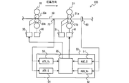
- FIG. 1 is a diagram illustrating a configuration example of a rolling control system according to an embodiment.
- the rolling control system 100 shown in FIG. 1 includes a rolling stand for rolling the material 10 to be rolled.
- the rolling stand includes a rolling stand 20 provided in the front stage in the rolling direction of the material 10 to be rolled, and a rolling stand 21 provided in the latter stage in the same rolling direction.
- the rolling stands 20 and 21 constitute a tandem rolling mill.
- the total number of rolling stands constituting the tandem rolling mill may be three or more.
- the rolling stand 20 has working rolls 20a and 20b for sandwiching the material 10 to be rolled.
- the rolling stand 21 has working rolls 21a and 21b.
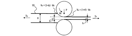
- FIG. 2 is a diagram showing a rolling phenomenon at a rolling stand and parameters related thereto.
- the material 10 to be rolled is pulled by the tension Tb on the entry side of the rolling stand and the tension Tf on the exit side of the rolling stand, and is crushed by the load P.
- the plate thickness H of the material to be rolled is reduced to the plate thickness h.
- the rolling phenomenon causes a load P, an advance rate f, and a reverse rate b.
- Speed Ve of the material being rolled 10 at the entry side of the rolling stand is represented by using a reverse rate b and the work roll speed V R.
- Speed Vo of the rolled material 10 in the entry side of the rolling stand is represented by using the work roll speed V R and the forward slip f.
- Roll stand 20 includes a speed controller 30 for controlling the work roll speed V R in the work rolls 20a and 20b.
- the rolling stand 20 also has a roll gap control device 40 that controls the roll gap S, which is the distance between the working rolls 20a and 20b.
- the rolling stand 21 has a speed control device 31 and a roll gap control device 41.
- Speed controller 31 controls the work roll speed V R of the rolling stand 21.
- the roll gap control device 41 controls the roll gap S of the rolling stand 21.
- the plate thickness of the material to be rolled 10 is important for the quality of the product. Therefore, a plate thickness meter 60 for measuring the plate thickness of the material 10 to be rolled is provided on the protruding side of the rolling stand 21. In rolling, it is also important to maintain product quality and ensure operational stability. Therefore, a tension meter 70 is provided between the rolling stands 20 and 21.
- the plate thickness gauge 60 and the tension gauge 70 are connected to the rolling control device 50.
- a plate thickness gauge having the same configuration as the plate thickness gauge 60 may be provided on the entry side and the exit side of the rolling stand 20.
- Tension gauges having the same configuration as the tension gauge 70 may be provided on the entry side of the rolling stand 20 and the exit side of the rolling stand 21.
- the rolling control device 50 includes a first plate thickness control unit 51, a second plate thickness control unit 52, a first tension control unit 53, a second tension control unit 54, and a control selection unit 55. , Is equipped.
- the first plate thickness control unit 51 performs roll gap-plate thickness control (hereinafter, also referred to as "AGC_S").
- AGC_S is an AGC for controlling the plate thickness of the material 10 to be rolled (that is, the plate thickness h shown in FIG. 2) on the exit side of the rolling stand 21 with the roll gap S of the rolling stand 21 as the control operation end. ..
- AGC_S is performed when the rolling speed is less than the boundary value TH.
- the second plate thickness control unit 52 performs speed-plate thickness control (hereinafter, also referred to as "AGC_Ve").
- AGC_Ve is an AGC for controlling the plate thickness of the material 10 to be rolled on the exit side of the rolling stand 21 with the speed Ve of the material 10 to be rolled on the entrance side of the rolling stand 21 as the control operation end.
- AGC_Ve is performed when the rolling speed is equal to or higher than the boundary value TH.
- the first tension control unit 53 performs speed-tension control (hereinafter, also referred to as "ATR_Ve").
- ATR_Ve controls the tension of the material 10 to be rolled between the rolling stands 20 and 21 (that is, the entrance side of the rolling stand 21) by using the speed Ve of the material 10 to be rolled on the entrance side of the rolling stand 21 as a control operation end.
- ATR for. ATR_Ve is performed when the rolling speed is less than the boundary value TH.
- the second tension control unit 54 performs roll gap-tension control (hereinafter, also referred to as “ATR_S”).
- ATR_S is an ATR for controlling the tension of the material 10 to be rolled between the rolling stands 20 and 21 with the roll gap S of the rolling stand 21 as a control operation end.
- ATR_S is performed when the rolling speed is equal to or higher than the boundary value TH.
- FIG. 3 is a block diagram showing the configurations of the first plate thickness control unit 51, the second plate thickness control unit 52, the first tension control unit 53, and the second tension control unit 54.
- These block diagrams are examples of control configurations of AGC_S, AGC_Ve, ATR_S and ATR_Ve. Therefore, it is possible to configure the control system with a configuration other than this control configuration.
- each control system is represented by integral control (I control).
- Each control system may be represented by proportional integration control (PI control) or differential proportional integration control (PID control).
- the output side plate thickness deviation ⁇ h is input to the first plate thickness control unit 51.
- the first plate thickness control unit 51 integrates the output side plate thickness deviation ⁇ h multiplied by the adjustment gain G SAGC and the conversion gain ( ⁇ (M + Q) / M) (I control).
- This conversion gain is a gain for converting the output side plate thickness deviation ⁇ h into the roll gap correction amount ⁇ S.
- M included in the conversion gain is the mill constant of the rolling stand, and Q is the plastic constant of the material to be rolled.
- the first plate thickness control unit 51 takes a deviation between the integrated value and the previous value to obtain a roll gap control amount ⁇ S AGC .
- the output side plate thickness deviation ⁇ h is input to the second plate thickness control unit 52.
- the second plate thickness control unit 52 integrates the output side plate thickness deviation ⁇ h multiplied by the adjustment gain GVAGC and the conversion gain (-1 / href) (I control). This conversion gain is a gain for converting the output side plate thickness deviation ⁇ h into the speed correction amount ⁇ Ve.
- the second plate thickness control unit 52 takes a deviation between the value obtained by dividing the integrated value by the speed Ve ( ⁇ Ve / Ve) and the previous value to obtain the speed control amount ⁇ ( ⁇ Ve / Ve) AGC .
- the input side tension deviation ⁇ Tb is input to the second tension control unit 54.
- the second tension control unit 54 integrates the input side tension deviation ⁇ T b multiplied by the adjustment gain G SATT and the conversion gain ((M + Q) ⁇ kb / M) (I control). This conversion gain is a gain for converting the input side tension deviation ⁇ Tb into the roll gap correction amount ⁇ S.
- the kb included in the conversion gain is a coefficient of influence of the fluctuation of the load P due to the fluctuation of the tension of the material to be rolled on the entrance side of the rolling stand on the plate thickness of the material to be rolled on the exit side of the rolling stand.
- the second tension control unit 54 takes a deviation between the integrated value and the previous value to obtain a roll gap control amount ⁇ S ATR .
- the input side tension deviation ⁇ Tb is input to the first tension control unit 53.
- the first tension control unit 53 integrates the input side tension deviation ⁇ T b multiplied by the adjustment gain G VATR and the conversion gain ( ⁇ V e ⁇ kb / h) (I control). This conversion gain is a gain for converting the input side tension deviation ⁇ Tb into the speed correction amount ⁇ Ve.
- the first tension control unit 53 takes a deviation between the value obtained by dividing the integrated value by the speed Ve ( ⁇ Ve / Ve) and the previous value to obtain the speed control amount ⁇ ( ⁇ Ve / Ve) ATR .
- the control selection unit 55 switches the combination of AGC and ATR described above according to the rolling speed. Specifically, when the rolling speed is less than the boundary value TH, a combination of AGC_S and ATR_Ve is selected. When the rolling speed is equal to or higher than the boundary value TH, the combination of AGC_Ve and ATR_S is selected.
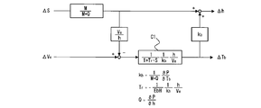
- FIG. 4 is a diagram showing the relationship between the control operation end in AGC and ATR and the control state quantity.
- the influence coefficient C1 is an influence coefficient exerted by the rolling phenomenon system on the entrance side of the rolling stand. Tr included in the influence coefficient C1 is a first-order lag constant. E included in the first-order lag constant Tr is Young's modulus, and b is the plate width.
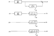
- FIG. 5 is a diagram showing various influence coefficients in the rolling phenomenon at the rolling stand.
- the influence coefficient C2 shown in the first stage of FIG. 5 is an influence coefficient on the output side plate thickness deviation ⁇ h by the roll gap correction amount ⁇ S.
- the influence coefficient C3 shown in the second stage is the influence coefficient that the roll gap correction amount ⁇ S has on the entry side tension deviation ⁇ Tb.
- the influence coefficient C4 shown in the third stage is an influence coefficient on the output side plate thickness deviation ⁇ h by the speed correction amount ⁇ Ve.
- the influence coefficient C4 shown in the fourth stage is the influence coefficient that the speed correction amount ⁇ Ve has on the entry side tension deviation ⁇ Tb.
- Impact factors C4 and C5 include velocity Ve in the denominator. Therefore, the influence coefficients C4 and C5 become smaller when the rolling speed is in the high speed range.
- the velocity Ve is also included in the denominator of the temporary delay constant Tr (see FIG. 4). Therefore, when the rolling speed is in the high speed range, the temporary delay constant Tr becomes small.
- the temporary delay constant Tr is included in the denominators of the influence coefficients C2 and C3. Therefore, when the rolling speed is in the high speed range, the influence coefficients C2 and C3 become large.
- the influence coefficients C4 and C5 become small, and the influence coefficients C2 and C3 become large.
- the influence coefficient C2 is a subtraction element of the output side plate thickness deviation ⁇ h. Therefore, it can be seen that when the rolling speed is in the high speed range, the entry side tension deviation ⁇ Tb is likely to change according to the roll gap correction amount ⁇ S. On the other hand, it can be seen that the inlet tension deviation ⁇ Tb and the outlet plate thickness deviation ⁇ h do not change so much when the speed correction amount ⁇ Ve changes. It can also be seen that the output side plate thickness deviation ⁇ h does not change so much when the roll gap correction amount ⁇ S changes.
- the above relationship is the exact opposite when the rolling speed is in the low speed range. That is, when the rolling speed is in the low speed range, the entry side tension deviation ⁇ Tb does not change so much when the roll gap correction amount ⁇ S changes. On the other hand, the entry-side tension deviation ⁇ Tb and the exit-side plate thickness deviation ⁇ h are likely to change depending on the speed correction amount ⁇ Ve. The output side plate thickness deviation ⁇ h is likely to change depending on the roll gap correction amount ⁇ S.
- FIG. 6 is a block diagram showing the configuration of the control selection unit 55.
- the control selection unit 55 includes a trigger circuit 55a, switches 55b and 55c, RAMP circuits 55d and 55e, a limiter 55f, a HOLD circuit 55g, and a pulse generator 55h. There is.
- the trigger circuit 55a outputs a trigger signal when the rolling speed is equal to or higher than the boundary value TH.
- the switch 55b switches from ON to OFF. That is, before the output of the trigger signal, the roll gap control amount ⁇ S AGC output from the first plate thickness control unit 51 is input to the roll gap control device 40. After the output of the trigger signal, this input is cut off by the switch 55b.
- the speed control amount ⁇ ( ⁇ Ve / Ve) ATR output from the first tension control unit 53 is input to the RAMP circuit 55d.
- the speed correction amount ⁇ Ve used in the calculation of the speed control amount ⁇ ( ⁇ Ve / Ve) ATR is also input to the RAMP circuit 55d.
- the speed control amount ⁇ ( ⁇ Ve / Ve) ATR input to the RAMP circuit 55d is input to the limiter 55f.
- the limiter 55f inputs the upper limit constraint to the speed control device 30 when the speed control amount ⁇ ( ⁇ Ve / Ve) ATR input to the limiter 55f conflicts with the upper limit constraint. Otherwise, the limiter 55f inputs the speed control amount ⁇ ( ⁇ Ve / Ve) ATR to the speed control device 30.
- the switch 55c is switched from OFF to ON. Then, the speed control amount ⁇ ( ⁇ Ve / Ve) AGC output from the second plate thickness control unit 52 is input to the limiter 55f.
- the trigger signal is output, zero is input to the RAMP circuit 55d via the switch 55c. Therefore, RAMP circuit 55d, the speed control amount outputted from the first tension control unit 53 before the output of the trigger signal ⁇ ( ⁇ Ve / Ve) ATR, and, in the calculation of the speed control amount ⁇ ( ⁇ Ve / Ve) ATR Reset the speed correction amount ⁇ Ve used. Then, after the trigger signal is output, nothing is output from the RAMP circuit 55d to the limiter 55f.
- the limiter 55f inputs the upper limit constraint to the speed control device 30 when the speed control amount ⁇ ( ⁇ Ve / Ve) AGC input to the limiter 55f conflicts with the upper limit constraint. Otherwise, the limiter 55f inputs the speed control amount ⁇ ( ⁇ Ve / Ve) AGC to the speed control device 30.
- the HOLD circuit 55g stores the speed correction amount ⁇ Ve output from the first tension control unit 53.
- the speed correction amount ⁇ Ve is stored in association with the pulse output signal from the pulse generator 55h.
- the speed correction amount ⁇ Ve at the timing of this output is input from the HOLD circuit 55g to the RAMP circuit 55e.
- the RAMP circuit 55e calculates and outputs a roll gap correction amount ⁇ S equivalent to the speed correction amount ⁇ Ve input to the RAMP circuit 55e. This roll gap correction amount ⁇ S is calculated by applying a predetermined adjustment gain to the speed correction amount ⁇ Ve.
- the roll gap control amount ⁇ S ATR output from the second tension control unit 54 is input to the roll gap control device 40 via the switch 55c.
- the roll gap correction amount ⁇ S calculated in the RAMP circuit 55e is added to the roll gap control amount ⁇ S ATR. That is, at the timing when the trigger signal is output, the roll gap control amount ⁇ S ATR to which the roll gap correction amount ⁇ S is added is input to the roll gap control device 40.
- ⁇ ( ⁇ Ve / Ve) The speed correction amount ⁇ Ve used in the calculation of the ATR is reset. Therefore, after the timing when the rolling speed exceeds the boundary value TH, only the speed control amount ⁇ ( ⁇ Ve / Ve) AGC output from the second plate thickness control unit 52 is input to the limiter 55f. Therefore, it is possible to avoid a situation in which the speed control amount ⁇ ( ⁇ Ve / Ve) AGC violates the upper limit constraint. Therefore, it is possible to avoid a situation in which it becomes difficult to continue the AGC after the timing when the rolling speed exceeds the boundary value TH.
- a speed correction amount ⁇ Ve that loosens the tension Tb is output from the first tension control unit 53 immediately before the rolling speed exceeds the boundary value TH. If such a speed correction amount ⁇ Ve is ignored, the tension Tb immediately after the rolling speed exceeds the boundary value TH becomes a value that is slightly pulled.
- a roll gap correction amount ⁇ S equivalent to the speed correction amount ⁇ Ve at the timing when the rolling speed exceeds the boundary value TH is added to the roll gap control amount ⁇ S ATR. Therefore, it is possible to prevent the tension Tb from fluctuating significantly after the timing when the rolling speed exceeds the boundary value TH.
- the first plate thickness control unit 51 and the like have been described as the functions of the rolling control device 50. However, these functions may be realized separately in a plurality of control devices.
Landscapes
- Engineering & Computer Science (AREA)
- Mechanical Engineering (AREA)
- Control Of Metal Rolling (AREA)
Abstract
Priority Applications (7)
| Application Number | Priority Date | Filing Date | Title |
|---|---|---|---|
| KR1020217023675A KR102536442B1 (ko) | 2020-01-15 | 2020-01-15 | 압연 제어 시스템 및 압연 제어 방법 |
| CN202080009823.4A CN113474097B (zh) | 2020-01-15 | 2020-01-15 | 轧制控制系统以及轧制控制方法 |
| BR112021014141-3A BR112021014141B1 (pt) | 2020-01-15 | Sistema de controle de laminação e método de controle de laminação | |
| PCT/JP2020/001065 WO2021144882A1 (fr) | 2020-01-15 | 2020-01-15 | Système de commande de laminage et procédé de commande de laminage |
| US17/427,671 US12042835B2 (en) | 2020-01-15 | 2020-01-15 | Rolling control system and rolling control method |
| JP2021571111A JP7197027B2 (ja) | 2020-01-15 | 2020-01-15 | 圧延制御システムおよび圧延制御方法 |
| TW109115218A TWI758724B (zh) | 2020-01-15 | 2020-05-07 | 壓延控制系統及壓延控制方法 |
Applications Claiming Priority (1)
| Application Number | Priority Date | Filing Date | Title |
|---|---|---|---|
| PCT/JP2020/001065 WO2021144882A1 (fr) | 2020-01-15 | 2020-01-15 | Système de commande de laminage et procédé de commande de laminage |
Publications (1)
| Publication Number | Publication Date |
|---|---|
| WO2021144882A1 true WO2021144882A1 (fr) | 2021-07-22 |
Family
ID=76864025
Family Applications (1)
| Application Number | Title | Priority Date | Filing Date |
|---|---|---|---|
| PCT/JP2020/001065 Ceased WO2021144882A1 (fr) | 2020-01-15 | 2020-01-15 | Système de commande de laminage et procédé de commande de laminage |
Country Status (6)
| Country | Link |
|---|---|
| US (1) | US12042835B2 (fr) |
| JP (1) | JP7197027B2 (fr) |
| KR (1) | KR102536442B1 (fr) |
| CN (1) | CN113474097B (fr) |
| TW (1) | TWI758724B (fr) |
| WO (1) | WO2021144882A1 (fr) |
Families Citing this family (3)
| Publication number | Priority date | Publication date | Assignee | Title |
|---|---|---|---|---|
| CN116783009B (zh) * | 2021-01-18 | 2025-11-25 | 首要金属科技德国有限责任公司 | 轧制机架的运行方法、轧制机架的控制系统及轧制单元 |
| CN114054513B (zh) * | 2021-11-02 | 2024-05-10 | 首钢集团有限公司 | 一种双机架平整机中带钢张力的控制方法及装置 |
| CN116727458B (zh) * | 2023-06-01 | 2026-04-14 | 首钢智新电磁材料(迁安)股份有限公司 | 冷轧机组的控制方法 |
Citations (4)
| Publication number | Priority date | Publication date | Assignee | Title |
|---|---|---|---|---|
| JPH11197728A (ja) * | 1998-01-14 | 1999-07-27 | Hitachi Ltd | タンデム圧延機の張力制御方法および制御装置 |
| JP2015112614A (ja) * | 2013-12-10 | 2015-06-22 | 株式会社日立製作所 | 圧延制御装置、圧延制御方法および圧延制御プログラム |
| JP2016093829A (ja) * | 2014-11-14 | 2016-05-26 | 株式会社日立製作所 | 圧延制御装置、圧延制御方法および圧延制御プログラム |
| JP2016221553A (ja) * | 2015-06-01 | 2016-12-28 | 株式会社日立製作所 | 圧延制御装置、圧延制御方法および圧延制御プログラム |
Family Cites Families (6)
| Publication number | Priority date | Publication date | Assignee | Title |
|---|---|---|---|---|
| JP5123346B2 (ja) * | 2010-03-25 | 2013-01-23 | 株式会社日立製作所 | 圧延機制御装置、圧延機制御装置の制御方法及びそのプログラム |
| JP2012176428A (ja) * | 2011-02-28 | 2012-09-13 | Hitachi Ltd | 圧延制御装置及び圧延制御方法 |
| JP5733230B2 (ja) * | 2012-02-09 | 2015-06-10 | 東芝三菱電機産業システム株式会社 | 熱間圧延ラインの制御装置 |
| JP6308927B2 (ja) | 2014-11-14 | 2018-04-11 | 株式会社日立製作所 | 圧延制御装置、圧延制御方法および圧延制御プログラム |
| JP6404195B2 (ja) * | 2015-09-16 | 2018-10-10 | 株式会社日立製作所 | プラント制御装置、圧延制御装置、プラント制御方法およびプラント制御プログラム |
| KR102049682B1 (ko) * | 2016-02-22 | 2019-11-28 | 도시바 미쓰비시덴키 산교시스템 가부시키가이샤 | 플랜트의 제어 장치 |
-
2020
- 2020-01-15 KR KR1020217023675A patent/KR102536442B1/ko active Active
- 2020-01-15 JP JP2021571111A patent/JP7197027B2/ja active Active
- 2020-01-15 WO PCT/JP2020/001065 patent/WO2021144882A1/fr not_active Ceased
- 2020-01-15 CN CN202080009823.4A patent/CN113474097B/zh active Active
- 2020-01-15 US US17/427,671 patent/US12042835B2/en active Active
- 2020-05-07 TW TW109115218A patent/TWI758724B/zh active
Patent Citations (4)
| Publication number | Priority date | Publication date | Assignee | Title |
|---|---|---|---|---|
| JPH11197728A (ja) * | 1998-01-14 | 1999-07-27 | Hitachi Ltd | タンデム圧延機の張力制御方法および制御装置 |
| JP2015112614A (ja) * | 2013-12-10 | 2015-06-22 | 株式会社日立製作所 | 圧延制御装置、圧延制御方法および圧延制御プログラム |
| JP2016093829A (ja) * | 2014-11-14 | 2016-05-26 | 株式会社日立製作所 | 圧延制御装置、圧延制御方法および圧延制御プログラム |
| JP2016221553A (ja) * | 2015-06-01 | 2016-12-28 | 株式会社日立製作所 | 圧延制御装置、圧延制御方法および圧延制御プログラム |
Also Published As
| Publication number | Publication date |
|---|---|
| KR102536442B1 (ko) | 2023-05-26 |
| JPWO2021144882A1 (fr) | 2021-07-22 |
| TW202128305A (zh) | 2021-08-01 |
| US20220126340A1 (en) | 2022-04-28 |
| CN113474097B (zh) | 2023-06-23 |
| US12042835B2 (en) | 2024-07-23 |
| KR20210107811A (ko) | 2021-09-01 |
| JP7197027B2 (ja) | 2022-12-27 |
| CN113474097A (zh) | 2021-10-01 |
| BR112021014141A2 (pt) | 2022-08-09 |
| TWI758724B (zh) | 2022-03-21 |
Similar Documents
| Publication | Publication Date | Title |
|---|---|---|
| WO2021144882A1 (fr) | Système de commande de laminage et procédé de commande de laminage | |
| KR101214348B1 (ko) | 판 압연기 및 그 제어 방법 | |
| KR101654993B1 (ko) | 압연 제어 장치, 압연 제어 방법 및 압연 제어 프로그램 | |
| CA2306588C (fr) | Appareil de commande de laminoirs a chaud et methode connexe | |
| JPS6016850B2 (ja) | コ−ルドタンデムミルの圧延速度揃速方法 | |
| US5806357A (en) | System and method for rolling tapered slabs | |
| DE102005046148A1 (de) | Motorsteuerung | |
| JPH0218168B2 (fr) | ||
| JP2001269706A (ja) | 連続冷間圧延時の形状制御方法 | |
| KR940703722A (ko) | 쌍교차 압연기의 가역압연 제어방법 | |
| JP3456077B2 (ja) | タンデム圧延機の板幅制御方法 | |
| JP7258790B2 (ja) | 圧延制御システムおよび圧延制御方法 | |
| JP3506119B2 (ja) | タンデム圧延機の圧延負荷配分変更方法 | |
| BR112021014141B1 (pt) | Sistema de controle de laminação e método de controle de laminação | |
| JP3255785B2 (ja) | タンデム圧延機における板厚制御方法 | |
| JP3224052B2 (ja) | 連続圧延機の板厚制御方法 | |
| JPS6132091B2 (fr) | ||
| KR950013244B1 (ko) | 압연기의 제어방법 및 장치 | |
| JP3304796B2 (ja) | 板圧延における形状制御方法 | |
| JPH02255208A (ja) | 板圧延における形状制御方法 | |
| JPH06269821A (ja) | 圧延機の平坦形状制御装置 | |
| JPH04294811A (ja) | 圧延機に於ける蛇行制御方法 | |
| KR20240095518A (ko) | 장력 제어 장치 | |
| JPH02224811A (ja) | 可逆式圧延機の板厚制御方法 | |
| JPH07100515A (ja) | 圧延機制御方法および装置 |
Legal Events
| Date | Code | Title | Description |
|---|---|---|---|
| ENP | Entry into the national phase |
Ref document number: 20217023675 Country of ref document: KR Kind code of ref document: A |
|
| 121 | Ep: the epo has been informed by wipo that ep was designated in this application |
Ref document number: 20913286 Country of ref document: EP Kind code of ref document: A1 |
|
| REG | Reference to national code |
Ref country code: BR Ref legal event code: B01A Ref document number: 112021014141 Country of ref document: BR |
|
| ENP | Entry into the national phase |
Ref document number: 2021571111 Country of ref document: JP Kind code of ref document: A |
|
| ENP | Entry into the national phase |
Ref document number: 112021014141 Country of ref document: BR Kind code of ref document: A2 Effective date: 20210719 |
|
| NENP | Non-entry into the national phase |
Ref country code: DE |
|
| 122 | Ep: pct application non-entry in european phase |
Ref document number: 20913286 Country of ref document: EP Kind code of ref document: A1 |