WO2021153463A1 - 包装容器、包装方法及び金属箔の輸送方法 - Google Patents
包装容器、包装方法及び金属箔の輸送方法 Download PDFInfo
- Publication number
- WO2021153463A1 WO2021153463A1 PCT/JP2021/002330 JP2021002330W WO2021153463A1 WO 2021153463 A1 WO2021153463 A1 WO 2021153463A1 JP 2021002330 W JP2021002330 W JP 2021002330W WO 2021153463 A1 WO2021153463 A1 WO 2021153463A1
- Authority
- WO
- WIPO (PCT)
- Prior art keywords
- packaging container
- bearing groove
- body frame
- end wall
- pallet
- Prior art date
- Legal status (The legal status is an assumption and is not a legal conclusion. Google has not performed a legal analysis and makes no representation as to the accuracy of the status listed.)
- Ceased
Links
Images







Classifications
-
- B—PERFORMING OPERATIONS; TRANSPORTING
- B65—CONVEYING; PACKING; STORING; HANDLING THIN OR FILAMENTARY MATERIAL
- B65D—CONTAINERS FOR STORAGE OR TRANSPORT OF ARTICLES OR MATERIALS, e.g. BAGS, BARRELS, BOTTLES, BOXES, CANS, CARTONS, CRATES, DRUMS, JARS, TANKS, HOPPERS, FORWARDING CONTAINERS; ACCESSORIES, CLOSURES, OR FITTINGS THEREFOR; PACKAGING ELEMENTS; PACKAGES
- B65D85/00—Containers, packaging elements or packages, specially adapted for particular articles or materials
- B65D85/67—Containers, packaging elements or packages, specially adapted for particular articles or materials for web or tape-like material
- B65D85/671—Containers, packaging elements or packages, specially adapted for particular articles or materials for web or tape-like material wound in flat spiral form
- B65D85/672—Containers, packaging elements or packages, specially adapted for particular articles or materials for web or tape-like material wound in flat spiral form on cores
-
- B—PERFORMING OPERATIONS; TRANSPORTING
- B65—CONVEYING; PACKING; STORING; HANDLING THIN OR FILAMENTARY MATERIAL
- B65D—CONTAINERS FOR STORAGE OR TRANSPORT OF ARTICLES OR MATERIALS, e.g. BAGS, BARRELS, BOTTLES, BOXES, CANS, CARTONS, CRATES, DRUMS, JARS, TANKS, HOPPERS, FORWARDING CONTAINERS; ACCESSORIES, CLOSURES, OR FITTINGS THEREFOR; PACKAGING ELEMENTS; PACKAGES
- B65D19/00—Pallets or like platforms, with or without side walls, for supporting loads to be lifted or lowered
- B65D19/0004—Rigid pallets without side walls
- B65D19/0006—Rigid pallets without side walls the load supporting surface being made of a single element
- B65D19/0008—Rigid pallets without side walls the load supporting surface being made of a single element forming a continuous plane contact surface
- B65D19/002—Rigid pallets without side walls the load supporting surface being made of a single element forming a continuous plane contact surface the base surface being made of more than one element
- B65D19/0024—Rigid pallets without side walls the load supporting surface being made of a single element forming a continuous plane contact surface the base surface being made of more than one element forming discontinuous or non-planar contact surfaces
-
- B—PERFORMING OPERATIONS; TRANSPORTING
- B65—CONVEYING; PACKING; STORING; HANDLING THIN OR FILAMENTARY MATERIAL
- B65D—CONTAINERS FOR STORAGE OR TRANSPORT OF ARTICLES OR MATERIALS, e.g. BAGS, BARRELS, BOTTLES, BOXES, CANS, CARTONS, CRATES, DRUMS, JARS, TANKS, HOPPERS, FORWARDING CONTAINERS; ACCESSORIES, CLOSURES, OR FITTINGS THEREFOR; PACKAGING ELEMENTS; PACKAGES
- B65D19/00—Pallets or like platforms, with or without side walls, for supporting loads to be lifted or lowered
- B65D19/02—Rigid pallets with side walls, e.g. box pallets
- B65D19/06—Rigid pallets with side walls, e.g. box pallets with bodies formed by uniting or interconnecting two or more components
- B65D19/20—Rigid pallets with side walls, e.g. box pallets with bodies formed by uniting or interconnecting two or more components made wholly or mainly of paper
-
- B—PERFORMING OPERATIONS; TRANSPORTING
- B65—CONVEYING; PACKING; STORING; HANDLING THIN OR FILAMENTARY MATERIAL
- B65D—CONTAINERS FOR STORAGE OR TRANSPORT OF ARTICLES OR MATERIALS, e.g. BAGS, BARRELS, BOTTLES, BOXES, CANS, CARTONS, CRATES, DRUMS, JARS, TANKS, HOPPERS, FORWARDING CONTAINERS; ACCESSORIES, CLOSURES, OR FITTINGS THEREFOR; PACKAGING ELEMENTS; PACKAGES
- B65D19/00—Pallets or like platforms, with or without side walls, for supporting loads to be lifted or lowered
- B65D19/36—Pallets comprising a flexible load carrier extending between guide elements, e.g. guide tubes
-
- B—PERFORMING OPERATIONS; TRANSPORTING
- B65—CONVEYING; PACKING; STORING; HANDLING THIN OR FILAMENTARY MATERIAL
- B65D—CONTAINERS FOR STORAGE OR TRANSPORT OF ARTICLES OR MATERIALS, e.g. BAGS, BARRELS, BOTTLES, BOXES, CANS, CARTONS, CRATES, DRUMS, JARS, TANKS, HOPPERS, FORWARDING CONTAINERS; ACCESSORIES, CLOSURES, OR FITTINGS THEREFOR; PACKAGING ELEMENTS; PACKAGES
- B65D19/00—Pallets or like platforms, with or without side walls, for supporting loads to be lifted or lowered
- B65D19/38—Details or accessories
- B65D19/44—Elements or devices for locating articles on platforms
-
- B—PERFORMING OPERATIONS; TRANSPORTING
- B65—CONVEYING; PACKING; STORING; HANDLING THIN OR FILAMENTARY MATERIAL
- B65D—CONTAINERS FOR STORAGE OR TRANSPORT OF ARTICLES OR MATERIALS, e.g. BAGS, BARRELS, BOTTLES, BOXES, CANS, CARTONS, CRATES, DRUMS, JARS, TANKS, HOPPERS, FORWARDING CONTAINERS; ACCESSORIES, CLOSURES, OR FITTINGS THEREFOR; PACKAGING ELEMENTS; PACKAGES
- B65D5/00—Rigid or semi-rigid containers of polygonal cross-section, e.g. boxes, cartons or trays, formed by folding or erecting one or more blanks made of paper
- B65D5/42—Details of containers or of foldable or erectable container blanks
- B65D5/44—Integral, inserted or attached portions forming internal or external fittings
- B65D5/441—Reinforcements
- B65D5/445—Reinforcements formed separately from the container
-
- B—PERFORMING OPERATIONS; TRANSPORTING
- B65—CONVEYING; PACKING; STORING; HANDLING THIN OR FILAMENTARY MATERIAL
- B65D—CONTAINERS FOR STORAGE OR TRANSPORT OF ARTICLES OR MATERIALS, e.g. BAGS, BARRELS, BOTTLES, BOXES, CANS, CARTONS, CRATES, DRUMS, JARS, TANKS, HOPPERS, FORWARDING CONTAINERS; ACCESSORIES, CLOSURES, OR FITTINGS THEREFOR; PACKAGING ELEMENTS; PACKAGES
- B65D5/00—Rigid or semi-rigid containers of polygonal cross-section, e.g. boxes, cartons or trays, formed by folding or erecting one or more blanks made of paper
- B65D5/42—Details of containers or of foldable or erectable container blanks
- B65D5/44—Integral, inserted or attached portions forming internal or external fittings
- B65D5/50—Internal supporting or protecting elements for contents
- B65D5/5021—Integral elements for containers formed by folding-up portions connected to a central panel from all sides
-
- B—PERFORMING OPERATIONS; TRANSPORTING
- B65—CONVEYING; PACKING; STORING; HANDLING THIN OR FILAMENTARY MATERIAL
- B65D—CONTAINERS FOR STORAGE OR TRANSPORT OF ARTICLES OR MATERIALS, e.g. BAGS, BARRELS, BOTTLES, BOXES, CANS, CARTONS, CRATES, DRUMS, JARS, TANKS, HOPPERS, FORWARDING CONTAINERS; ACCESSORIES, CLOSURES, OR FITTINGS THEREFOR; PACKAGING ELEMENTS; PACKAGES
- B65D5/00—Rigid or semi-rigid containers of polygonal cross-section, e.g. boxes, cartons or trays, formed by folding or erecting one or more blanks made of paper
- B65D5/42—Details of containers or of foldable or erectable container blanks
- B65D5/64—Lids
- B65D5/68—Telescope flanged lids
-
- B—PERFORMING OPERATIONS; TRANSPORTING
- B65—CONVEYING; PACKING; STORING; HANDLING THIN OR FILAMENTARY MATERIAL
- B65D—CONTAINERS FOR STORAGE OR TRANSPORT OF ARTICLES OR MATERIALS, e.g. BAGS, BARRELS, BOTTLES, BOXES, CANS, CARTONS, CRATES, DRUMS, JARS, TANKS, HOPPERS, FORWARDING CONTAINERS; ACCESSORIES, CLOSURES, OR FITTINGS THEREFOR; PACKAGING ELEMENTS; PACKAGES
- B65D85/00—Containers, packaging elements or packages, specially adapted for particular articles or materials
- B65D85/66—Containers, packaging elements or packages, specially adapted for particular articles or materials for jumbo rolls; for rolls of floor covering
-
- B—PERFORMING OPERATIONS; TRANSPORTING
- B65—CONVEYING; PACKING; STORING; HANDLING THIN OR FILAMENTARY MATERIAL
- B65D—CONTAINERS FOR STORAGE OR TRANSPORT OF ARTICLES OR MATERIALS, e.g. BAGS, BARRELS, BOTTLES, BOXES, CANS, CARTONS, CRATES, DRUMS, JARS, TANKS, HOPPERS, FORWARDING CONTAINERS; ACCESSORIES, CLOSURES, OR FITTINGS THEREFOR; PACKAGING ELEMENTS; PACKAGES
- B65D2519/00—Pallets or like platforms, with or without side walls, for supporting loads to be lifted or lowered
- B65D2519/00004—Details relating to pallets
- B65D2519/00009—Materials
- B65D2519/00014—Materials for the load supporting surface
- B65D2519/00019—Paper
-
- B—PERFORMING OPERATIONS; TRANSPORTING
- B65—CONVEYING; PACKING; STORING; HANDLING THIN OR FILAMENTARY MATERIAL
- B65D—CONTAINERS FOR STORAGE OR TRANSPORT OF ARTICLES OR MATERIALS, e.g. BAGS, BARRELS, BOTTLES, BOXES, CANS, CARTONS, CRATES, DRUMS, JARS, TANKS, HOPPERS, FORWARDING CONTAINERS; ACCESSORIES, CLOSURES, OR FITTINGS THEREFOR; PACKAGING ELEMENTS; PACKAGES
- B65D2519/00—Pallets or like platforms, with or without side walls, for supporting loads to be lifted or lowered
- B65D2519/00004—Details relating to pallets
- B65D2519/00009—Materials
- B65D2519/00049—Materials for the base surface
- B65D2519/00054—Paper
-
- B—PERFORMING OPERATIONS; TRANSPORTING
- B65—CONVEYING; PACKING; STORING; HANDLING THIN OR FILAMENTARY MATERIAL
- B65D—CONTAINERS FOR STORAGE OR TRANSPORT OF ARTICLES OR MATERIALS, e.g. BAGS, BARRELS, BOTTLES, BOXES, CANS, CARTONS, CRATES, DRUMS, JARS, TANKS, HOPPERS, FORWARDING CONTAINERS; ACCESSORIES, CLOSURES, OR FITTINGS THEREFOR; PACKAGING ELEMENTS; PACKAGES
- B65D2519/00—Pallets or like platforms, with or without side walls, for supporting loads to be lifted or lowered
- B65D2519/00004—Details relating to pallets
- B65D2519/00009—Materials
- B65D2519/00119—Materials for the construction of the reinforcements
- B65D2519/00124—Paper
-
- B—PERFORMING OPERATIONS; TRANSPORTING
- B65—CONVEYING; PACKING; STORING; HANDLING THIN OR FILAMENTARY MATERIAL
- B65D—CONTAINERS FOR STORAGE OR TRANSPORT OF ARTICLES OR MATERIALS, e.g. BAGS, BARRELS, BOTTLES, BOXES, CANS, CARTONS, CRATES, DRUMS, JARS, TANKS, HOPPERS, FORWARDING CONTAINERS; ACCESSORIES, CLOSURES, OR FITTINGS THEREFOR; PACKAGING ELEMENTS; PACKAGES
- B65D2519/00—Pallets or like platforms, with or without side walls, for supporting loads to be lifted or lowered
- B65D2519/00004—Details relating to pallets
- B65D2519/00009—Materials
- B65D2519/00154—Materials for the side walls
- B65D2519/00159—Paper
-
- B—PERFORMING OPERATIONS; TRANSPORTING
- B65—CONVEYING; PACKING; STORING; HANDLING THIN OR FILAMENTARY MATERIAL
- B65D—CONTAINERS FOR STORAGE OR TRANSPORT OF ARTICLES OR MATERIALS, e.g. BAGS, BARRELS, BOTTLES, BOXES, CANS, CARTONS, CRATES, DRUMS, JARS, TANKS, HOPPERS, FORWARDING CONTAINERS; ACCESSORIES, CLOSURES, OR FITTINGS THEREFOR; PACKAGING ELEMENTS; PACKAGES
- B65D2519/00—Pallets or like platforms, with or without side walls, for supporting loads to be lifted or lowered
- B65D2519/00004—Details relating to pallets
- B65D2519/00009—Materials
- B65D2519/00189—Materials for the lid or cover
- B65D2519/00194—Paper
-
- B—PERFORMING OPERATIONS; TRANSPORTING
- B65—CONVEYING; PACKING; STORING; HANDLING THIN OR FILAMENTARY MATERIAL
- B65D—CONTAINERS FOR STORAGE OR TRANSPORT OF ARTICLES OR MATERIALS, e.g. BAGS, BARRELS, BOTTLES, BOXES, CANS, CARTONS, CRATES, DRUMS, JARS, TANKS, HOPPERS, FORWARDING CONTAINERS; ACCESSORIES, CLOSURES, OR FITTINGS THEREFOR; PACKAGING ELEMENTS; PACKAGES
- B65D2519/00—Pallets or like platforms, with or without side walls, for supporting loads to be lifted or lowered
- B65D2519/00004—Details relating to pallets
- B65D2519/00258—Overall construction
- B65D2519/00263—Overall construction of the pallet
- B65D2519/00273—Overall construction of the pallet made of more than one piece
-
- B—PERFORMING OPERATIONS; TRANSPORTING
- B65—CONVEYING; PACKING; STORING; HANDLING THIN OR FILAMENTARY MATERIAL
- B65D—CONTAINERS FOR STORAGE OR TRANSPORT OF ARTICLES OR MATERIALS, e.g. BAGS, BARRELS, BOTTLES, BOXES, CANS, CARTONS, CRATES, DRUMS, JARS, TANKS, HOPPERS, FORWARDING CONTAINERS; ACCESSORIES, CLOSURES, OR FITTINGS THEREFOR; PACKAGING ELEMENTS; PACKAGES
- B65D2519/00—Pallets or like platforms, with or without side walls, for supporting loads to be lifted or lowered
- B65D2519/00004—Details relating to pallets
- B65D2519/00258—Overall construction
- B65D2519/00283—Overall construction of the load supporting surface
- B65D2519/00288—Overall construction of the load supporting surface made of one piece
-
- B—PERFORMING OPERATIONS; TRANSPORTING
- B65—CONVEYING; PACKING; STORING; HANDLING THIN OR FILAMENTARY MATERIAL
- B65D—CONTAINERS FOR STORAGE OR TRANSPORT OF ARTICLES OR MATERIALS, e.g. BAGS, BARRELS, BOTTLES, BOXES, CANS, CARTONS, CRATES, DRUMS, JARS, TANKS, HOPPERS, FORWARDING CONTAINERS; ACCESSORIES, CLOSURES, OR FITTINGS THEREFOR; PACKAGING ELEMENTS; PACKAGES
- B65D2519/00—Pallets or like platforms, with or without side walls, for supporting loads to be lifted or lowered
- B65D2519/00004—Details relating to pallets
- B65D2519/00258—Overall construction
- B65D2519/00283—Overall construction of the load supporting surface
- B65D2519/00293—Overall construction of the load supporting surface made of more than one piece
-
- B—PERFORMING OPERATIONS; TRANSPORTING
- B65—CONVEYING; PACKING; STORING; HANDLING THIN OR FILAMENTARY MATERIAL
- B65D—CONTAINERS FOR STORAGE OR TRANSPORT OF ARTICLES OR MATERIALS, e.g. BAGS, BARRELS, BOTTLES, BOXES, CANS, CARTONS, CRATES, DRUMS, JARS, TANKS, HOPPERS, FORWARDING CONTAINERS; ACCESSORIES, CLOSURES, OR FITTINGS THEREFOR; PACKAGING ELEMENTS; PACKAGES
- B65D2519/00—Pallets or like platforms, with or without side walls, for supporting loads to be lifted or lowered
- B65D2519/00004—Details relating to pallets
- B65D2519/00258—Overall construction
- B65D2519/00313—Overall construction of the base surface
- B65D2519/00323—Overall construction of the base surface made of more than one piece
-
- B—PERFORMING OPERATIONS; TRANSPORTING
- B65—CONVEYING; PACKING; STORING; HANDLING THIN OR FILAMENTARY MATERIAL
- B65D—CONTAINERS FOR STORAGE OR TRANSPORT OF ARTICLES OR MATERIALS, e.g. BAGS, BARRELS, BOTTLES, BOXES, CANS, CARTONS, CRATES, DRUMS, JARS, TANKS, HOPPERS, FORWARDING CONTAINERS; ACCESSORIES, CLOSURES, OR FITTINGS THEREFOR; PACKAGING ELEMENTS; PACKAGES
- B65D2519/00—Pallets or like platforms, with or without side walls, for supporting loads to be lifted or lowered
- B65D2519/00004—Details relating to pallets
- B65D2519/00258—Overall construction
- B65D2519/00313—Overall construction of the base surface
- B65D2519/00328—Overall construction of the base surface shape of the contact surface of the base
- B65D2519/00333—Overall construction of the base surface shape of the contact surface of the base contact surface having a stringer-like shape
-
- B—PERFORMING OPERATIONS; TRANSPORTING
- B65—CONVEYING; PACKING; STORING; HANDLING THIN OR FILAMENTARY MATERIAL
- B65D—CONTAINERS FOR STORAGE OR TRANSPORT OF ARTICLES OR MATERIALS, e.g. BAGS, BARRELS, BOTTLES, BOXES, CANS, CARTONS, CRATES, DRUMS, JARS, TANKS, HOPPERS, FORWARDING CONTAINERS; ACCESSORIES, CLOSURES, OR FITTINGS THEREFOR; PACKAGING ELEMENTS; PACKAGES
- B65D2519/00—Pallets or like platforms, with or without side walls, for supporting loads to be lifted or lowered
- B65D2519/00004—Details relating to pallets
- B65D2519/00258—Overall construction
- B65D2519/00398—Overall construction reinforcements
- B65D2519/00432—Non-integral, e.g. inserts
- B65D2519/00437—Non-integral, e.g. inserts on the load supporting surface
-
- B—PERFORMING OPERATIONS; TRANSPORTING
- B65—CONVEYING; PACKING; STORING; HANDLING THIN OR FILAMENTARY MATERIAL
- B65D—CONTAINERS FOR STORAGE OR TRANSPORT OF ARTICLES OR MATERIALS, e.g. BAGS, BARRELS, BOTTLES, BOXES, CANS, CARTONS, CRATES, DRUMS, JARS, TANKS, HOPPERS, FORWARDING CONTAINERS; ACCESSORIES, CLOSURES, OR FITTINGS THEREFOR; PACKAGING ELEMENTS; PACKAGES
- B65D2519/00—Pallets or like platforms, with or without side walls, for supporting loads to be lifted or lowered
- B65D2519/00004—Details relating to pallets
- B65D2519/00258—Overall construction
- B65D2519/00398—Overall construction reinforcements
- B65D2519/00432—Non-integral, e.g. inserts
- B65D2519/00452—Non-integral, e.g. inserts on the walls
-
- B—PERFORMING OPERATIONS; TRANSPORTING
- B65—CONVEYING; PACKING; STORING; HANDLING THIN OR FILAMENTARY MATERIAL
- B65D—CONTAINERS FOR STORAGE OR TRANSPORT OF ARTICLES OR MATERIALS, e.g. BAGS, BARRELS, BOTTLES, BOXES, CANS, CARTONS, CRATES, DRUMS, JARS, TANKS, HOPPERS, FORWARDING CONTAINERS; ACCESSORIES, CLOSURES, OR FITTINGS THEREFOR; PACKAGING ELEMENTS; PACKAGES
- B65D2519/00—Pallets or like platforms, with or without side walls, for supporting loads to be lifted or lowered
- B65D2519/00004—Details relating to pallets
- B65D2519/00258—Overall construction
- B65D2519/00492—Overall construction of the side walls
- B65D2519/00502—Overall construction of the side walls whereby at least one side wall is made of two or more pieces
-
- B—PERFORMING OPERATIONS; TRANSPORTING
- B65—CONVEYING; PACKING; STORING; HANDLING THIN OR FILAMENTARY MATERIAL
- B65D—CONTAINERS FOR STORAGE OR TRANSPORT OF ARTICLES OR MATERIALS, e.g. BAGS, BARRELS, BOTTLES, BOXES, CANS, CARTONS, CRATES, DRUMS, JARS, TANKS, HOPPERS, FORWARDING CONTAINERS; ACCESSORIES, CLOSURES, OR FITTINGS THEREFOR; PACKAGING ELEMENTS; PACKAGES
- B65D2519/00—Pallets or like platforms, with or without side walls, for supporting loads to be lifted or lowered
- B65D2519/00004—Details relating to pallets
- B65D2519/00547—Connections
- B65D2519/00552—Structures connecting the constitutive elements of the pallet to each other, i.e. load supporting surface, base surface and/or separate spacer
- B65D2519/00557—Structures connecting the constitutive elements of the pallet to each other, i.e. load supporting surface, base surface and/or separate spacer without separate auxiliary elements
- B65D2519/00562—Structures connecting the constitutive elements of the pallet to each other, i.e. load supporting surface, base surface and/or separate spacer without separate auxiliary elements chemical connection, e.g. glued, welded, sealed
-
- B—PERFORMING OPERATIONS; TRANSPORTING
- B65—CONVEYING; PACKING; STORING; HANDLING THIN OR FILAMENTARY MATERIAL
- B65D—CONTAINERS FOR STORAGE OR TRANSPORT OF ARTICLES OR MATERIALS, e.g. BAGS, BARRELS, BOTTLES, BOXES, CANS, CARTONS, CRATES, DRUMS, JARS, TANKS, HOPPERS, FORWARDING CONTAINERS; ACCESSORIES, CLOSURES, OR FITTINGS THEREFOR; PACKAGING ELEMENTS; PACKAGES
- B65D2519/00—Pallets or like platforms, with or without side walls, for supporting loads to be lifted or lowered
- B65D2519/00004—Details relating to pallets
- B65D2519/00547—Connections
- B65D2519/00577—Connections structures connecting side walls, including corner posts, to each other
- B65D2519/00582—Connections structures connecting side walls, including corner posts, to each other structures intended to be disassembled, i.e. collapsible or dismountable
-
- B—PERFORMING OPERATIONS; TRANSPORTING
- B65—CONVEYING; PACKING; STORING; HANDLING THIN OR FILAMENTARY MATERIAL
- B65D—CONTAINERS FOR STORAGE OR TRANSPORT OF ARTICLES OR MATERIALS, e.g. BAGS, BARRELS, BOTTLES, BOXES, CANS, CARTONS, CRATES, DRUMS, JARS, TANKS, HOPPERS, FORWARDING CONTAINERS; ACCESSORIES, CLOSURES, OR FITTINGS THEREFOR; PACKAGING ELEMENTS; PACKAGES
- B65D2519/00—Pallets or like platforms, with or without side walls, for supporting loads to be lifted or lowered
- B65D2519/00004—Details relating to pallets
- B65D2519/00547—Connections
- B65D2519/00577—Connections structures connecting side walls, including corner posts, to each other
- B65D2519/00616—Connections structures connecting side walls, including corner posts, to each other structures not intended to be disassembled
- B65D2519/00621—Connections structures connecting side walls, including corner posts, to each other structures not intended to be disassembled sidewalls directly connected to each other
-
- B—PERFORMING OPERATIONS; TRANSPORTING
- B65—CONVEYING; PACKING; STORING; HANDLING THIN OR FILAMENTARY MATERIAL
- B65D—CONTAINERS FOR STORAGE OR TRANSPORT OF ARTICLES OR MATERIALS, e.g. BAGS, BARRELS, BOTTLES, BOXES, CANS, CARTONS, CRATES, DRUMS, JARS, TANKS, HOPPERS, FORWARDING CONTAINERS; ACCESSORIES, CLOSURES, OR FITTINGS THEREFOR; PACKAGING ELEMENTS; PACKAGES
- B65D2519/00—Pallets or like platforms, with or without side walls, for supporting loads to be lifted or lowered
- B65D2519/00004—Details relating to pallets
- B65D2519/00547—Connections
- B65D2519/00636—Connections structures connecting side walls to the pallet
- B65D2519/00641—Structures intended to be disassembled
-
- B—PERFORMING OPERATIONS; TRANSPORTING
- B65—CONVEYING; PACKING; STORING; HANDLING THIN OR FILAMENTARY MATERIAL
- B65D—CONTAINERS FOR STORAGE OR TRANSPORT OF ARTICLES OR MATERIALS, e.g. BAGS, BARRELS, BOTTLES, BOXES, CANS, CARTONS, CRATES, DRUMS, JARS, TANKS, HOPPERS, FORWARDING CONTAINERS; ACCESSORIES, CLOSURES, OR FITTINGS THEREFOR; PACKAGING ELEMENTS; PACKAGES
- B65D2519/00—Pallets or like platforms, with or without side walls, for supporting loads to be lifted or lowered
- B65D2519/00004—Details relating to pallets
- B65D2519/00547—Connections
- B65D2519/00706—Connections structures connecting the lid or cover to the side walls or corner posts
- B65D2519/00711—Connections structures connecting the lid or cover to the side walls or corner posts removable lid or covers
-
- B—PERFORMING OPERATIONS; TRANSPORTING
- B65—CONVEYING; PACKING; STORING; HANDLING THIN OR FILAMENTARY MATERIAL
- B65D—CONTAINERS FOR STORAGE OR TRANSPORT OF ARTICLES OR MATERIALS, e.g. BAGS, BARRELS, BOTTLES, BOXES, CANS, CARTONS, CRATES, DRUMS, JARS, TANKS, HOPPERS, FORWARDING CONTAINERS; ACCESSORIES, CLOSURES, OR FITTINGS THEREFOR; PACKAGING ELEMENTS; PACKAGES
- B65D2519/00—Pallets or like platforms, with or without side walls, for supporting loads to be lifted or lowered
- B65D2519/00004—Details relating to pallets
- B65D2519/00736—Details
- B65D2519/0081—Elements or devices for locating articles
- B65D2519/0082—Elements or devices for locating articles in the side wall
-
- B—PERFORMING OPERATIONS; TRANSPORTING
- B65—CONVEYING; PACKING; STORING; HANDLING THIN OR FILAMENTARY MATERIAL
- B65D—CONTAINERS FOR STORAGE OR TRANSPORT OF ARTICLES OR MATERIALS, e.g. BAGS, BARRELS, BOTTLES, BOXES, CANS, CARTONS, CRATES, DRUMS, JARS, TANKS, HOPPERS, FORWARDING CONTAINERS; ACCESSORIES, CLOSURES, OR FITTINGS THEREFOR; PACKAGING ELEMENTS; PACKAGES
- B65D2519/00—Pallets or like platforms, with or without side walls, for supporting loads to be lifted or lowered
- B65D2519/00004—Details relating to pallets
- B65D2519/00736—Details
- B65D2519/00935—Details with special means for nesting or stacking
- B65D2519/0094—Details with special means for nesting or stacking nestable
Definitions
- the present invention relates to a packaging container, a packaging method, and a method for transporting metal leaf.
- Patent Document 1 Japanese Patent Application Laid-Open No. 2018-30591
- Patent Document 2 Japanese Patent Application Laid-Open No. 2018-30591
- An example of a corrugated cardboard container for accommodating a roll-shaped object in a tubular body by supporting support shafts provided at both ends of the roll-shaped object is described.
- a transport machine such as a crane to lift a corrugated cardboard container via a rope or the like and transport it in a suspended state.
- the container may be deformed, or the container may be tilted during transportation, making it difficult to stably transport the container.
- the present disclosure discloses a packaging container, a packaging method, and a metal leaf transport capable of suppressing damage or deformation of the packaging container and stably transporting the packaging container even when the packaging container is suspended in the air. Provide a method.
- an embodiment of the present invention has, on one side, a pallet having legs, a body frame arranged on the pallet and having bearing grooves on end wall portions facing each other, and a body frame. It is a corrugated cardboard packaging container having a lid portion provided on the pallet and a leg portion arranged inside the end wall portion of the pallet.
- the storage object is housed in the packaging container, and a binding member is provided between the top surface of the lid of the packaging container containing the storage object and the bottom surface of the pallet. It is a packaging method including bundling with.
- a storage object in which a material made of a metal foil is wound around an axis is housed in the packaging container, and a storage object is stored by using a binding member.
- a packaging container capable of suppressing damage or deformation of the packaging container and stably transporting the packaging container even when the packaging container is suspended in the air. can.
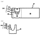
- FIG. 7A is a development view of a body frame body member forming the body frame body
- FIG. 7B is a development view of a reinforcing pad laminated on the body frame body.
- FIG. 8A shows a developed view of the auxiliary frame
- FIG. 8B shows a developed view of the auxiliary frame
- FIG. 8B shows a first bearing groove, a second bearing groove, and an object to be accommodated when the auxiliary frame is laminated on the body frame body to form the body frame. It is a top view which shows the positional relationship of. It is a top view which shows the state which accommodated the accommodating member in a body frame. It is the external perspective view of the upper presser part. It is a front view of a spacer pad. It is an external perspective view of a lid part. It is an external perspective view which shows the folded state at the time of storage of a lid part. It is the schematic which shows the packing state of the packaging container at the time of transportation.
- the packaging container 1 As shown in FIG. 1, the packaging container 1 according to the embodiment of the present invention includes a pallet 2 having legs 21 and a body provided on the pallet 2 and having bearing grooves 31 on end wall portions 32 facing each other. A frame 3 and a lid portion 4 provided above the body frame 3 are provided. The bearing groove 31 may further include an upper pressing portion 5 for suppressing the movement of the shaft support portion 11 supported by the bearing groove 31.
- Each member of the packaging container 1 according to the embodiment of the present invention may be made of a material such as wood or plastic, and is more preferably made of corrugated cardboard.
- the object 10 to be accommodated in the packaging container 1 is a roll-shaped object in which various materials such as metal, plastic, paper, synthetic resin and the like, sheets, foils, strips and the like are wound around the axis 12. If so, it is not particularly limited. In particular, in the present embodiment, the case where the copper foil roll in which the copper foil or the copper alloy foil is wound around the axis 12 is used as the accommodation object 10 will be described, but the present invention is not limited to this.
- the accommodation object 10 includes shaft support portions 11 projecting from both ends in the axial direction of the shaft center 12.
- the shaft support portion 11 of the object to be accommodated 10 By supporting the shaft support portion 11 of the object to be accommodated 10 by the bearing groove 31 of the body frame 3, the object to be accommodated 10 can be suspended in the air and accommodated in the body frame 3.
- the influence of external force and gravity applied to the roll portion of the contained object 10 can be reduced, and the deformation of the contained object 10 can be suppressed.
- the pallet 2 rises from the bottom surface 22 on which the body frame 3 is placed, the bottom surface 22, and is continuous with the pair of end wall portions 23 facing each other and the end wall portions 23, and rises from the bottom surface 22.
- a pair of side wall portions 24 facing each other and leg portions 21 connected to the bottom surface 22 are provided.
- the legs 21 are formed on a laminated body portion 21a in which a plurality of corrugated cardboard plates in which a wavy core is bonded between liners are laminated and bonded, and on the laminated body portion 21a. It is provided with a sheet-shaped leg reinforcing portion 21b that is bonded to each other.
- the laminated body portion 21a is typically composed of 5 to 20 corrugated cardboard plates having a thickness of about 5 to 10 mm in the horizontal direction (vertical direction with respect to the vertical direction) with respect to the bottom surface 22 via an adhesive layer. It has a structure that is laminated to some extent.
- the leg portion reinforcing portion 21b is attached so as to cover the end surface of the laminated body portion 21a to reinforce the bottom surface of the leg portion 21.
- leg reinforcing portion 21b By arranging the leg reinforcing portion 21b on the laminated body portion 21a, the hardness of the bottom surface of the leg portion 21 is increased, and problems during transportation due to damage of the leg portion 21 during transportation and deformation such as dents are prevented. Can be done.
- the load weight on which the pallet 2 can be loaded and the strength of the leg portion 21 can be adjusted by adjusting the material of the liner and core of the corrugated cardboard plate constituting the laminated body portion 21a, or the number of laminated corrugated cardboard plates.
- the leg portions 21 are arranged inside (center side) of the end wall portion 23 of the pallet 2 at a certain interval S from the end wall portion 23.
- This interval S functions as a holding surface 26 for hooking and holding the lifting tool on both ends of the packaging container 1.
- the packaging container 1 can be transported more smoothly because the packaging container 1 can be lifted and stably transported by bringing a lifting member such as a rope into contact with the holding surface 26. It becomes possible to do.
- a transport method of lifting and transporting the packaging container 1 it is possible to transport the packaging container 1 packed with heavy objects by a crane or the like even in a facility having a structure in which a forklift or the like cannot be inserted. ..
- the transportation means By increasing the choices of the transportation means in this way, the restrictions on the delivery destination facility of the storage object 10 which is the content of the packaging container 1 are relaxed. It can also improve the safety of the work site.
- a bottom surface reinforcing portion 25 capable of reinforcing the bottom surface 22 of the pallet 2 is arranged between the legs 21 of the bottom surface 22 of the pallet 2.
- the bottom surface 22 of the pallet 2 can be reinforced to suppress the deformation of the packaging container 1 and the strength can be improved.
- a binding member 71 such as a band described later, even if the binding force of the binding member 71 is strong enough to sink into the bottom surface reinforcing portion 25, the pallet 2 itself is deformed. Can be suppressed.
- the binding strength can also be improved.
- the arrangement position, shape and thickness of the bottom surface reinforcing portion 25 are not particularly limited, and various selections can be made according to the application. By further arranging the bottom surface reinforcing portion 25 on the holding surface 26, damage to the packaging container 1 during transportation can be further suppressed.
- the pallet 2 is provided on the side wall portion 24 with four folding curves RL extending diagonally upward from each of the four corner portions C of the rectangular bottom surface 22 of the pallet 2.
- the folding curve RL is inclined at an inclination of about 45 degrees with respect to the tangent line L1 between the bottom surface 22 and the side wall portion 24 from the point (corner portion C) where the bottom surface 22, the end wall portion 23, and the side wall portion 24 meet. is doing.
- the body frame 3 includes a body frame main body 30 and at least one auxiliary frame 34, 35 laminated on the body frame main body 30.
- a body frame main body 30 and at least one auxiliary frame 34, 35 laminated on the body frame main body 30.
- auxiliary frame 34, 35 laminated on the body frame main body 30.
- the body frame main body 30 has a pair of end wall portions 32 facing each other and a pair of side wall portions 33 facing each other, and has a side wall portion 33 between the end wall portions 32 facing each other.
- the body frame main body 30 has a first bearing groove 310 for supporting the shaft support portion 11 of the accommodation object 10 in the end wall portion 32, respectively.
- the body frame body 30 becomes a tubular body as shown in FIG. 1 by connecting two body frame body members 37 as shown in FIG. 7A.
- the body frame main body member 37 includes an end wall portion 32, a side wall portion 33 continuous with the end wall portion 32, and a joint margin portion 36 formed at the end portion of the end wall portion 32.
- the body frame body 30 is obtained by connecting the joint portion 36 of one body frame body member 37 to the end portion of the side wall portion 33 of the other body frame body member 37.
- the first bearing groove 310 is provided with an accommodating portion 311 capable of accommodating the shaft support portion 11 at the lower end portion and an accommodating portion 313 capable of accommodating the upper pressing portion 5 at the upper end portion.
- a locking portion 312 protruding toward the inner center of the first bearing groove 310 is provided in order to abut and support the lower end portion 54 (see FIG. 10) of the upper pressing portion 5. Be prepared. When the bottom portion of the lower end portion 54 of the upper pressing portion 5 and the upper surface of the locking portion 312 come into contact with each other, it is possible to prevent the upper pressing portion 5 from slipping down to the lower side of the first bearing groove 310.
- the width W1 of the lower end portion of the first bearing groove 310 in the arc horizontal direction of the first bearing groove 310 has a dimension equivalent to the diameter of the shaft support portion 11 of the accommodation object 10.
- the horizontal width W2 of the upper end portion of the first bearing groove 310 is larger than W1 of the lower end portion of the first bearing groove 310.
- One or a plurality of reinforcing pads 38 as shown in FIG. 7B may be attached to the first bearing groove 310 of the body frame body 30 on the end wall portion 32 of the body frame body member 37. As a result, the load bearing capacity of the first bearing groove 310 can be improved.
- the reinforcing pad 38 includes a bearing groove 318 having accommodating portions 3118, 3138 and locking portions 3128 having substantially the same shape as the accommodating portions 311 and 313 and the locking portion 312, respectively. Since the bearing groove 318 and the first bearing groove 310 have substantially the same shape, rattling when the shaft support portion 11 is placed can be prevented. On the other hand, since the body frame main body 30 and the reinforcing pad 38 are made of corrugated cardboard, the first bearing groove 310 and the bearing are subjected to the weight of the accommodation object 10 loaded on the bearing groove 318 and the first bearing groove 310 via the shaft support portion 11. Since the groove 318 may be deformed, it may be necessary to provide a certain amount of dimensional allowance.
- the shapes of the first bearing groove 310 of the body frame main body 30 and the bearing groove 318 of the reinforcing pad 38 do not have to have exactly the same shape.
- the number of layers of the reinforcing pad 38 on the end wall portion 32 can be appropriately adjusted in consideration of the weight of the storage object 10 to be stored and the length of the shaft support portion 11 of the storage object 10.
- At least one auxiliary frame 34, 35 is laminated on the body frame body 30.
- the auxiliary frame 34 includes an auxiliary side wall portion 334, a first auxiliary end wall portion 324a and a second auxiliary end wall portion 324b arranged at both ends of the auxiliary side wall portion 334.
- the first auxiliary end wall portion 324a has a second bearing groove 314a including accommodating portions 3114, 3134 and locking portions 3124 having substantially the same shape as the first bearing groove 310.
- the second auxiliary end wall portion 324b includes a transport arm insertion groove 314b in which the width W3 in the arc horizontal direction at the lower end portion is smaller than the arc horizontal width W1 at the lower end portion of the first bearing groove 310.
- the auxiliary frame 35 can have the same configuration as the auxiliary frame 34. That is, the auxiliary frame 35 includes an auxiliary side wall portion 335, a first auxiliary end wall portion 325a arranged at both ends of the auxiliary side wall portion 335, and a second auxiliary end wall portion 325b.
- the first auxiliary end wall portion 325a includes a second bearing groove 315a having a housing portion 3115, 3135 and a locking portion 3125 having substantially the same shape as the first bearing groove 310.
- the second auxiliary end wall portion 325b includes a transport arm insertion groove 315b whose lower end arc horizontal width W3 is smaller than the lower end arc horizontal width W1 of the first bearing groove 310.
- the fact that the width W3 is smaller than the width W1 means that the body frame main body 30, the auxiliary frame 34, and the auxiliary frame 35 are laminated, and the first bearing groove 310 and / or the end wall portion 32 and the first auxiliary end wall portion 325a are provided.
- the shaft support portion 11 is placed on the second bearing groove 315a, the outside of the shaft support portion 11 comes into contact with the second auxiliary end wall portion 324b, and the second auxiliary end wall portion 324b is one of the axial centers 12 of the shaft support portion 11. Cover the portion (see FIG. 8B).
- the second auxiliary end wall portion 324b can limit the axial movement of the storage object 10 housed in the packaging container 1.
- the width W3 of the transport arm insertion groove 314b may be smaller than the width W1 to the extent that the axial movement of the accommodation object 10 can be restricted.
- the shaft center 12 of the shaft support portion 11 has a hollow structure and the transport arm of the transport device of the object to be accommodated 10 is inserted and transported inside the shaft center 12, it will be described later.
- the width W3 is wide enough to allow the transfer arm to be inserted, in the case of a roll-shaped object in which the storage object 10 is wound around a hollow axial center 12, when it is placed in the packaging container 1.
- a transport device can be used, and the stored object 10 can be efficiently transported by a machine.
- a reinforcing pad 39a having a transport arm groove 391 having a width W3 substantially the same as that of the second auxiliary end wall portion 324b at the lower end portion may be provided on the first auxiliary end wall portion 324a of the auxiliary frame 34.
- a reinforcing pad 39b having a transport arm groove 392 having a width W3 substantially the same as that of the second auxiliary end wall portion 324b at the lower end portion may be provided.
- the auxiliary frame 35 can also be provided with reinforcing pads 39a and 39b. As a result, the rigidity of the entire packaging container 1 can be increased, and the strength of the packaging container 1 during suspension and transportation can be ensured. Reinforcing pads 39a and 39b may be omitted if necessary.
- the second bearing groove 315a and the transport arm insertion groove 314b are stacked on the body frame body 30 in this order on one of the first bearing grooves 310 of the body frame body 30.
- the first auxiliary end wall portion 325a and the second auxiliary end wall portion 324b are laminated.
- FIG. 9 is a top view showing a method of superimposing the body frame main body 30 and the auxiliary frames 34 and 35 when the reinforcing pads 39a and 39b are attached to the auxiliary frames 34 and 35.
- Auxiliary frames 34 and 35 are superposed on the outer surface of the body frame body 30 so as to face each other with the body frame body 30 in between.
- the first auxiliary end wall portion 325a of the auxiliary frame 35 provided with the second bearing groove 315a is laminated on the outer surface of one end wall portion 32 of the body frame main body 30.
- a reinforcing pad 39a is attached to the outer surface of the first auxiliary end wall portion 325a, and the second auxiliary end wall portion 324b of the auxiliary frame 34 provided with the transport arm insertion groove 314b is laminated on the outer surface.
- a reinforcing pad 39b is attached to the outer surface of the second auxiliary end wall portion 324b.
- the first auxiliary end wall portion 324a of the auxiliary frame 34 provided with the second bearing groove 314a is laminated on the outer surface of the other end wall portion 32 of the body frame main body 30.
- a reinforcing pad 39a is attached to the outer surface of the first auxiliary end wall portion 324a, and the second auxiliary end wall portion 325b of the auxiliary frame 35 provided with the transport arm insertion groove 315b is laminated on the outer surface.
- a reinforcing pad 39b is attached to the outer surface of the second auxiliary end wall portion 325b.
- the shaft support portion 11 on the right side of the paper surface of FIG. 9 is supported by the end wall portion 32 and the first auxiliary end wall portion 325a, and is supported on the outer surface of the first auxiliary end wall portion 325a.
- the inner surface of the reinforcing pad 39a attached by bonding is substantially in contact with the end surface of the shaft support portion 11 of the accommodation object 10, and suppresses the movement of the shaft support portion 11 in the direction parallel to the axial direction. As a result, it is possible to provide a configuration suitable for suspended transportation while suppressing damage and deformation of the packaging container 1.
- the materials constituting the body frame main body 30, auxiliary frames 34, 35 and the reinforcing pads 38, 39a, 39b may be of the same type, but when members having different strengths are used, the first bearing groove 310 may be In order to support the shaft support portion 11 of the accommodation object 10 on the innermost side, it is preferable that the body frame main body 30 is formed of a material having higher strength than the auxiliary frames 34 and 35, more specifically, a material having high compressive strength.
- the materials of the auxiliary frames 34 and 35 and the reinforcing pads 38, 39a and 39b are the same as those of the body frame main body 30.
- the use of a material having high compressive strength may increase the material cost. Therefore, depending on the strength required for the packaging container 1, it may be appropriately selected whether or not the materials of the auxiliary frames 34 and 35 and the reinforcing pads 38, 39a and 39b are the same as those of the body frame main body 30.
- the bearing groove 31 of the body frame 3 that supports the shaft support portion 11 of the object to be accommodated 10 is affected by the weight of the object to be accommodated 10 and an external force during transportation, and is easily deformed or damaged such as crushed. Therefore, it is preferable that the bearing groove 31 of the body frame 3 is arranged in the vertical direction of the leg portion 21.
- the shaft of the object 10 to be accommodated is among the first bearing groove 310 and the second bearing grooves 314a and 315a constituting the bearing groove 31.
- the first bearing groove 310 of the body frame body 30 that supports the branch 11 on the innermost side may be affected by the weight of the object 10 to be accommodated and an external force during transportation. Therefore, at least the leg portion 21 of the pallet 2 is arranged on the vertical line (upward in the vertical direction) between the first bearing groove 310 of the body frame main body 30 and the innermost contact point between the shaft support portion 11 of the accommodation object 10. As described above, it is preferable to configure the packaging container 1.
- the shaft support portion 11 and the first bearing groove 310 with respect to the leg portion 21 are formed by adjusting the number of the body frame main body 30, the auxiliary frames 34, 35, and the reinforcing pads 38, 39a, 39b. Adjusting the position of the innermost contact point of.
- the weight of the accommodation object 10 transmitted from the shaft support portion 11 supported by the bearing groove 31 of the body frame 3 can be supported by the legs 21, so that the accommodation object 10 can be transported even for a long period of time. It is possible to prevent deformation and breakage of the packaging container 1 due to the weight of the packaging container 1.
- auxiliary frames 34 and 35 arranged so as to surround the body frame main body 30 are arranged directly above the holding surface 26 for hooking and holding the lifting tool on both ends of the packaging container 1, thereby having a load bearing capacity. It is possible to support the weight of the object 10 to be accommodated without difficulty, so that a stable transport state can be realized.
- both the tubular body frame main body 30 and the auxiliary frames 34 and 35 can be folded and folded, so that the storage area can be saved.
- the body frame main body 30, the auxiliary frames 34, and 35 can be assembled and used, so that the packaging container 1 can be stored more efficiently without requiring a large storage space as in the conventional wooden container. can.
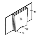
- the upper pressing portion 5 includes a base pad 51 and a guide pad 52 laminated near the central portion of the base pad 51. Below the guide pad 52, a curved surface portion 53 having substantially the same shape as the curved surface of the outer peripheral surface of the shaft support portion 11 of the accommodation object 10 and restricting the vertical movement of the accommodation object 10 during transportation is formed. Since the lower end portion 54 of the upper pressing portion 5 comes into contact with and stops on the locking portion 312 of the body frame main body 30, the upper pressing portion 5 is less likely to be displaced due to vibration during transportation, and the upper pressing portion 5 is stabilized in the accommodating portion 313. Can be accommodated for a long period of time.
- the guide pad 52 on the base pad 51 has a structure in which a plurality of corrugated cardboard plates are laminated with an adhesive. It is preferable that the laminated height of the guide pad 52 is adjusted so as to match the thickness of the laminated portion laminated on the end wall portion 32 of the body frame main body 30.
- the upper pressing portion 5 in the bearing groove 31 of the body frame 3 it is possible to limit the movement of the accommodation object 10 in the body frame 3 during transportation. Further, by arranging the spacer pad 6 provided with the groove 61 as shown in FIG. 11, the gap between the end face of the accommodation object 10 and the body frame main body 30 is filled, thereby moving the accommodation object 10 in the axial direction. Can be suppressed.
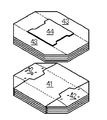
- the lid portion 4 has a top surface 41 that covers the upper part of the body frame 3 and a part of the side wall portion 33 (auxiliary side wall portion 334, 335) of the body frame 3 that extends downward from the top surface 41.
- a top surface reinforcing portion 44 arranged on the top surface 41 is provided.
- a binding member 71 is arranged on the top surface reinforcing portion 44 in order to bind the packaging container 1, but the top surface reinforcing portion 44 is cushioned by the arrangement of the top surface reinforcing portion 44. Since it functions as a material, it is possible to suppress deformation and breakage of the lid portion 4 itself.
- Notches 45 that are concave in the central direction are formed at both ends of the top surface reinforcing portion 44.
- the end wall portion 42 is provided with a protruding portion 46 that projects downward from the tip of the end wall portion 42.
- the notch 45 and the protrusion 46 are formed so as to have substantially the same shape. Since the cutout portion 45 and the protruding portion 46 have substantially the same shape, as shown in FIG. 13, when the lid portion 4 is bent and folded during storage of the lid portion 4, the cutout portion of the top surface reinforcing portion 44 of the lid portion 4 is formed. Since the 45 and the protruding portion 46 of the end wall portion 42 can be overlapped with each other facing each other, the stacking height when the lid portion 4 is laminated and stored in a folded state can be reduced.
- the protruding portion 46 has a blindfold function. Since the body frame 3 has a first bearing groove 310, a second bearing groove 314a, 315a and a transfer arm insertion groove 314b, 315b, when packaged as it is, the first bearing groove 310, the second bearing groove 314a, 315a and the transfer arm The insertion grooves 314b and 315b are exposed to the outside. This leads to adhesion of dust to the first bearing groove 310, the second bearing groove 314a, 315a, the transport arm insertion groove 314b, 315b, or the object 10 to be accommodated therein, which is not preferable.
- the first bearing groove 310, the second bearing groove 314a, 315a and the transport arm insertion groove 314b, 315b are covered, and dust from the outside is prevented from entering. be able to.
- the lid portion 4 is provided on the side wall portion 43 with four folding curves RL2 extending diagonally from the four corner portions P of the top surface 41.
- the folding curve RL2 has an inclination of about 45 degrees from the point where the top surface 41, the end wall portion 42, and the side wall portion 43 meet (corner portion P) with respect to the line where the top surface 41 and the side wall portion 43 meet. It is inclined.
- the pallet 2, the body frame main body 30, the auxiliary frames 34, 35, and the lid 4 constituting the body frame 3 are assembled so as to have a predetermined three-dimensional shape.
- the body frame body 30 is arranged on the pallet 2, and the auxiliary frames 34 and 35 are arranged around the body frame body 30 to assemble the body frame 3, thereby arranging the body frame 3 on the pallet 2.
- the shaft support portion 11 of the object to be accommodated 10 is supported by a transport arm or the like of a transport machine and transported into the body frame 3, and the shaft support portion 11 is housed so as to be supported by the bearing groove 31 of the body frame 3.
- the upper pressing portion 5 is inserted from above the bearing groove 31, and the shaft support portion 11 supported by the bearing groove 31 is fixed from above by the upper pressing portion 5.
- a spacer pad 6 is arranged in the gap between the end of the object 10 and the body frame body 30 to fill the gap between the end face of the object 10 and the body frame 30.
- the lid portion 4 is arranged on the body frame 3, and as shown in FIG. 14, a binding member 71 such as a band-shaped band is arranged between the top surface of the lid portion 4 and the bottom surface of the pallet 2, and the packaging container. The periphery of 1 is bound by a band-shaped binding member 71.
- the lifting member for lifting and transporting is brought into contact with the holding surface 26 provided between the end wall portion 23 and the leg portion 21 on the bottom surface 22 of the pallet 2 of the packaging container 1 containing the storage object 10.
- the packaging container is lifted, a plurality of packaging containers 1 are laminated, a reinforcing member is arranged on the uppermost packaging container 1, the laminated packaging container is bound by using a band-shaped binding member 71, and this is transported. Transport to the ground.
- the leg portions 21 of the pallet 2 are located inside the end wall portion 23 of the pallet 2 at regular intervals.
- the packaging container 1 can be lifted and transported while the storage object 10 is suspended in the air at an appropriate position. That is, it is possible to take a transport mode other than lifting and transporting the packaging container 1 with the claws of a forklift as in the conventional case, which leads to diversification of transport means and improves transport efficiency.
- the end wall portion 32 is formed in a laminated structure by the body frame main body 30 and the auxiliary frames 34 and 35, and the bearing groove 31 of the body frame 3 (the first bearing groove 310 of the body frame main body 30) that supports the gravity of the object 10 to be accommodated is formed.
- the bearing groove 31 of the body frame 3 (the first bearing groove 310 of the body frame main body 30) that supports the gravity of the object 10 to be accommodated is formed.
- the packaging container 1 is made of corrugated cardboard, it can be folded and stored during storage, which saves pace and reduces the weight as compared with the conventional wooden container. Therefore, the transportation means CO 2 It is also expected to reduce the amount of corrugated cardboard, and it is possible to provide more environmentally friendly packaging containers.
- the body frame 3 is composed of three members of the body frame main body 30 and the auxiliary frames 34 and 35 which are overlapped so as to surround the body frame main body 30 is shown.
- the auxiliary frames 34 and 35 do not necessarily have to have the auxiliary side wall portions 334 and 335.
- an auxiliary frame having an auxiliary end wall portion having the same shape as the reinforcing pad 38 is laminated on the end wall portion 32 of the body frame body 30 so as to at least face the end wall portion 32 of the body frame body 30. You may.
- the example in which the auxiliary frames 34 and 35 are arranged on the outside of the body frame main body 30 is described, but it is also possible to arrange the auxiliary frames 34 and 35 on the inside of the body frame main body 30.
Landscapes
- Engineering & Computer Science (AREA)
- Mechanical Engineering (AREA)
- Pallets (AREA)
- Packaging Of Machine Parts And Wound Products (AREA)
- Basic Packing Technique (AREA)
Abstract
包装容器の破損や変形を抑制でき、包装容器を宙吊り状態にして搬送した場合においても安定して搬送することが可能な包装容器、包装方法及び金属箔の輸送方法を提供する。脚部21を備えるパレット2と、パレット2上に配置され、互いに対向する端壁部32に軸受溝31を有する胴枠3と、胴枠3上に設けられる蓋部4と、を備え、脚部21が、パレット2の端壁部23よりも内側に配置される段ボール製の包装容器である。
Description
本発明は、包装容器、包装方法及び金属箔の輸送方法に関する。
ロール状物の搬送のための種々の包装容器が知られている。例えば特開2018-30591号公報(特許文献1)には、方形状のパレットと、パレット上に載置された胴枠と、段ボール製の蓋とを備え、胴枠に形成された軸受溝がロール状物の両端部に設けられる支持軸を支持することにより、ロール状物を筒状体内に収容する段ボール製の容器の例が記載されている。
特許文献1に記載されるような段ボール製の容器を搬送する際は、フォークリフトのリフト爪を容器底部の桁間に差し込んで荷役することが行われる。しかしながら、リフト爪の差し込み位置が不適切であると、リフト爪が容器を突き破り、容器に破損を生じさせる場合がある。
別の搬送方法としては、クレーン等の搬送機を用いてロープなどを介して段ボール製の容器を吊り上げ、宙吊り状態にして搬送することが考えられる。しかしながら、収容物の収容形態及び重量によっては、容器の変形が生じる場合、或いは搬送中に容器が傾き、安定して搬送することが難しい場合がある。
上記課題に鑑み、本開示は、包装容器の破損や変形を抑制でき、包装容器を宙吊り状態にして搬送した場合においても安定して搬送することが可能な包装容器、包装方法及び金属箔の輸送方法を提供する。
上記課題を解決するために、本発明の実施の形態は一側面において、脚部を備えるパレットと、パレット上に配置され、互いに対向する端壁部に軸受溝を有する胴枠と、胴枠上に設けられる蓋部と、を備え、脚部が、パレットの端壁部よりも内側に配置される段ボール製の包装容器である。
本発明の実施の形態は別の一側面において、上記包装容器内に収容対象物を収容し、収容対象物を収容した包装容器の蓋部の天面とパレットとの底面との間を結束部材を用いて結束することを含む包装方法である。
本発明の実施の形態は更に別の一側面において、上記包装容器内に、金属箔からなる材料を軸心の周りに巻回した収容対象物を収容し、結束部材を用いて、収容対象物を収容した包装容器の蓋部の天面とパレットとの底面との間を結束し、収容対象物を収容した包装容器のパレットの端壁部と脚部の間の底面に設けられた保持面に、吊り上げ運搬用の吊り上げ部材を当接させ、包装容器を吊り上げて輸送することを含む金属箔の輸送方法である。
本開示によれば、包装容器の破損や変形を抑制でき、包装容器を宙吊り状態にして搬送した場合においても安定して搬送することが可能な包装容器、包装方法及び金属箔の輸送方法が提供できる。
以下、図面を参照しながら本発明の実施の形態について説明する。なお、以下に示す実施の形態はこの発明の技術的思想を具体化するための装置や方法を例示するものであって、この発明の技術的思想は、各構成部品の構造、配置及び手順等を下記のものに特定するものではない。本発明の実施の形態に開示されている複数の構成要素は、適宜な組み合わせにより、種々の発明を形成できる。例えば、この実施形態に示される全構成要素からいくつかの構成要素を削除してもよいし、異なる実施形態の構成要素を適宜組み合わせてもよい。
(包装容器)
本発明の実施の形態に係る包装容器1は、図1に示すように、脚部21を備えるパレット2と、パレット2上に配置され、互いに対向する端壁部32に軸受溝31を備える胴枠3と、胴枠3の上方に設けられた蓋部4とを備える。軸受溝31内には、軸受溝31に支えられる軸支部11の移動を押さえるための上押え部5を更に備えていてもよい。本発明の実施の形態に係る包装容器1の各部材は、木材、プラスチック等の素材で形成されていてもよく、段ボール製であることがより好ましい。
本発明の実施の形態に係る包装容器1は、図1に示すように、脚部21を備えるパレット2と、パレット2上に配置され、互いに対向する端壁部32に軸受溝31を備える胴枠3と、胴枠3の上方に設けられた蓋部4とを備える。軸受溝31内には、軸受溝31に支えられる軸支部11の移動を押さえるための上押え部5を更に備えていてもよい。本発明の実施の形態に係る包装容器1の各部材は、木材、プラスチック等の素材で形成されていてもよく、段ボール製であることがより好ましい。
包装容器1内に収容される収容対象物10としては、金属、プラスチック、紙、合成樹脂などの種々のフィルム、シート、箔、条等の材料を軸心12の周りに巻回したロール状物であれば特に限定されない。特に、本実施形態では、銅箔又は銅合金箔を軸心12の周りに巻回した銅箔ロールを収容対象物10として利用する場合を説明するがこれに限定されるものではない。
図2に示すように、収容対象物10は、軸心12の軸方向の両端部からそれぞれ突出する軸支部11を備える。収容対象物10の軸支部11を、胴枠3の軸受溝31で支えることにより、収容対象物10を宙吊り状態にして胴枠3内に収容することができる。これにより、収容対象物10のロール部分へ加わる外力及び重力の影響を小さくでき、収容対象物10の変形を抑制できる。
図3に示すように、パレット2は、胴枠3を載置する底面22と、底面22から立ち上がり、互いに対向する一対の端壁部23と、端壁部23と連続し、底面22から立ち上がり、互いに対向する一対の側壁部24と、底面22に接続された脚部21とを備える。パレット2に端壁部23及び側壁部24が配置されることにより、パレット2上に積載される胴枠3を所定の位置に収容して胴枠3の位置ずれを抑制できる。
脚部21は、図4に示すように、波状の中芯をライナーとライナーとの間に貼り合わせた段ボール板を複数枚積層して貼り合わせた積層体部21aと、積層体部21a上に貼り合わされたシート状の脚部補強部21bとを備える。積層体部21aは、典型的には、厚さ5~10mm程度の段ボール板が、接着剤層を介して、底面22に対して水平方向(鉛直方向に対して垂直方向)に5~20枚程度積層された構造を有する。脚部補強部21bは積層体部21aの端面を覆うように貼り合わされ、脚部21の底面を補強する。
積層体部21a上に、脚部補強部21bが配置されることにより、脚部21の底面の硬度を高め、搬送時の脚部21の破損及びへこみ等の変形による搬送時の不具合を防ぐことができる。なお、パレット2が積載可能な積載重量及び脚部21の強度は、積層体部21aを構成する段ボール板のライナー及び中芯の材質、或いは段ボール板の積層枚数を調節することにより調整できる。
図5に示すように、脚部21は、パレット2の端壁部23よりも内側(中央側)に、端壁部23から一定の間隔Sを空けて配置されている。この間隔Sは、包装容器1の両端に吊り上げ具を引っかけて保持するための保持面26として機能する。本実施形態に係る包装容器1によれば、保持面26に対し、ロープ等の吊り上げ用部材を当接させて包装容器1を吊り上げて安定して搬送できるため、包装容器1をより円滑に搬送することが可能となる。
また、包装容器1を吊り上げて搬送する搬送方法を採ることができると、フォークリフト等が入れない構造の施設内においても、重量物を梱包した包装容器1をクレーン等によって搬送することが可能となる。このように搬送手段の選択肢を増加させることで、包装容器1の内容物である収容対象物10の搬入先施設についての制限が緩和される。また、作業現場の安全性向上にもつながり得る。
パレット2の底面22の脚部21の間には、パレット2の底面22を補強可能な底面補強部25が配置されることが好ましい。これにより、パレット2の底面22を補強して包装容器1の変形を抑制し、強度を向上できる。また、後述するバンド等の結束部材71で包装容器1を結束する際に、結束部材71の結束力が、底面補強部25にめり込む程に強力な場合であっても、パレット2自体の変形を抑制できる。結束部材71を底面補強部25と接触させて底面補強部25に対してめり込ませるように結束することで、結束強度も向上できる。
前述のように、保持面26にロープ等の吊り上げ用部材を当接させ、包装容器1を吊り上げる場合、包装容器1の中心付近に荷重がかかり、結果包装容器1が変形してしまう場合もある。このような問題に対し、底面補強部25を備えることにより、包装容器1を吊り上げて搬送する際に包装容器1が中心付近で曲がることを抑制できる。フォークリフト等を用いて包装容器1を搬送する場合に、フォークリフトの爪の操作を誤った際においても、パレット2の底面22の破損を抑制できる。
底面補強部25の配置位置、形状及び厚さは特に限定されず、用途に応じて種々選択することができる。底面補強部25は、更に保持面26に配置することで、運搬時の包装容器1の破損を更に抑制できる。
パレット2は、側壁部24上に、パレット2の矩形の底面22の4つの角部Cからそれぞれ斜め方向上方へと延びる4本の折曲線RLを備える。折曲線RLは、底面22と端壁部23と側壁部24の3面の接する点(角部C)から、底面22と側壁部24との接する線L1に対して約45度の傾きで傾斜している。折曲線RLを山折りに折り曲げることで、端壁部23及び側壁部24を折りたたんだ状態で、パレット2を積層して保管できるため、包装容器1として組み立てる前の保管スペースを削減できる。包装容器1を利用する場合には、パレット2の端壁部23及び側壁部24を立ち上げるだけでよいため、パレット2の組み立ても容易である。
図1に示すように、胴枠3は、胴枠本体30と、胴枠本体30上に積層される少なくとも1の補助枠34、35を備える。このように胴枠3を複数の部材で構成することにより、胴枠3が備える軸受溝31をはじめとした胴枠本体30の強度向上を図ることができる。補助枠34、35は、省略することもできる。
胴枠本体30は、互いに対向する一対の端壁部32及び互いに対向する一対の側壁部33を有し、互いに対向する端壁部32の間に側壁部33を有する。胴枠本体30は、端壁部32に、収容対象物10の軸支部11を支えるための第1軸受溝310をそれぞれ有する。
胴枠本体30は、図7(a)に示すような胴枠本体部材37を2枚繋ぎ合わせることにより、図1に示すような筒状体となる。胴枠本体部材37は、端壁部32と、端壁部32と連続する側壁部33と、端壁部32の端部に形成された継ぎしろ部36とを備える。一方の胴枠本体部材37の継ぎしろ部36を他方の胴枠本体部材37の側壁部33の端部とつなぎ合わせることで、胴枠本体30が得られる。
第1軸受溝310は、軸支部11を収容可能な収容部311を下端部に備え、上押え部5を収容可能な収容部313を上端部に備える。第1軸受溝310の側面には、上押え部5の下端部54(図10参照)と当接して支えるために、第1軸受溝310の内側中央方向に向かって突出する係止部312を備える。上押え部5の下端部54の底部と係止部312の上面とが互いに接触することにより、上押え部5が第1軸受溝310の下方側へずれ落ちることを抑制できる。
第1軸受溝310は、第1軸受溝310の下端部の円弧水平方向の幅W1が、収容対象物10の軸支部11の直径と同等の寸法を有する。これにより、第1軸受溝310の下端部に、収容対象物10の両端部から突出する軸支部11を収容可能となっている。第1軸受溝310の上端部の水平方向の幅W2は、第1軸受溝310の下端部のW1よりも大きい。これにより、胴枠本体30の端壁部32の破損を防ぎながら、第1軸受溝310内に収容対象物10の軸支部11を収容しやすくできる。
胴枠本体30の第1軸受溝310には、図7(b)に示すような、補強パッド38を、胴枠本体部材37の端壁部32上へ1又は複数枚貼り合わせてもよい。これにより、第1軸受溝310の耐荷重性の向上を図ることができる。
補強パッド38は、収容部311、313及び係止部312とそれぞれ略同一の形状を有する収容部3118、3138及び係止部3128を備える軸受溝318を備える。軸受溝318と第1軸受溝310とが略同一の形状を有することにより、軸支部11を載置したときのガタツキを防止することができる。一方、胴枠本体30及び補強パッド38は段ボール製であるため、軸支部11を介して軸受溝318及び第1軸受溝310に荷重される収容対象物10の重量により第1軸受溝310及び軸受溝318の変形も生じ得ることから、ある程度の寸法の余裕を設けることを必要とする場合もある。よって、胴枠本体30の第1軸受溝310及び補強パッド38の軸受溝318の形状は厳密に同一形状を有していなくともよい。なお、補強パッド38の端壁部32への積層枚数は、収納予定の収容対象物10の重量及び収容対象物10の軸支部11の長さを考慮して適宜調整できる。
胴枠本体30上には、少なくとも1の補助枠34、35が積層される。補助枠34は、図8(a)に示すように、補助側壁部334と、補助側壁部334の両端に配置された第1の補助端壁部324a及び第2の補助端壁部324bとを備える。第1の補助端壁部324aは、第1軸受溝310と略同一の形状の収容部3114、3134及び係止部3124を備える第2軸受溝314aを有する。第2の補助端壁部324bは、下端部の円弧水平方向の幅W3が、第1軸受溝310の下端部の円弧水平方向の幅W1よりも小さい搬送アーム挿入溝314bを備える。
補助枠35は、補助枠34と同様の構成を有することができる。即ち、補助枠35は、補助側壁部335と、補助側壁部335の両端に配置された第1の補助端壁部325aと、第2の補助端壁部325bとを備える。第1の補助端壁部325aは、第1軸受溝310と略同一の形状の収容部3115、3135及び係止部3125を有する第2軸受溝315aを備える。第2の補助端壁部325bは、下端部の円弧水平方向の幅W3が第1軸受溝310の下端部の円弧水平方向の幅W1よりも小さい搬送アーム挿入溝315bを備える。
幅W3が幅W1より小さいということは、胴枠本体30、補助枠34、補助枠35を積層し、端壁部32及び第1の補助端壁部325aが備える第1軸受溝310及び/又は第2軸受溝315a上に軸支部11を載置すると、軸支部11の外側が第2の補助端壁部324bと接し、第2の補助端壁部324bが軸支部11の軸心12の一部を覆う(図8(b)参照)。これにより、第2の補助端壁部324bが、包装容器1に収容した収容対象物10の軸方向の移動を制限することができる。その結果、包装容器1の搬送中に軸支部11が軸受溝31から脱落し、収容対象物10が落下して、損傷する可能性を低減することができる。
搬送アーム挿入溝314bの幅W3は、収容対象物10の軸方向の移動を制限し得る程度に、幅W1より小さければ差し支えない。中でも、軸支部11の軸心12が中空構造を有しており、軸心12の内側に収容対象物10の搬送器具の搬送アームを挿入し、搬送するような態様においては、後述するような好ましい態様が存在する。例えば、幅W3を搬送アームが挿入可能な程度の幅とすると、収容対象物10が中空を有する軸心12に巻回されたロール状物の場合、これを包装容器1内に載置する際、搬送器具を用いることができ、収容対象物10を機械により効率良く運搬することができる。
補助枠34の第1の補助端壁部324a上には、第2の補助端壁部324bと略同一の幅W3を下端部に有する搬送アーム溝391を備える補強パッド39aを備えてもよい。補助枠34の第2の補助端壁部324b上には、第2の補助端壁部324bと略同一の幅W3を下端部に有する搬送アーム溝392を備える補強パッド39bを備えてもよい。補助枠35も補助枠34と同様に、補強パッド39a、39bを備えることができる。これにより、包装容器1全体の剛性を高め、包装容器1の宙吊り搬送時の強度を確保できる。補強パッド39a、39bは必要に応じて省略することもできる。
胴枠3の組み立て時には、胴枠本体30の一方の第1軸受溝310上に、第2軸受溝315a及び搬送アーム挿入溝314bが、この順で重ねられるように、胴枠本体30上に、第1の補助端壁部325a及び第2の補助端壁部324bが積層される。
図9は、補助枠34、35に補強パッド39a、39bを取り付けた場合の胴枠本体30及び補助枠34、35の重ね合わせ方法を表す上面図である。胴枠本体30を間に介して互いに対向するように、補助枠34、35が、胴枠本体30の外側表面上に重ね合わされている。
図9の紙面右側に示されるように、胴枠本体30の一方の端壁部32の外側表面には、第2軸受溝315aを備える補助枠35の第1の補助端壁部325aが積層される。第1の補助端壁部325aの外側表面上には、補強パッド39aが貼り付けられ、この外側表面に、搬送アーム挿入溝314bを備える補助枠34の第2の補助端壁部324bが積層される。第2の補助端壁部324bの外側表面には補強パッド39bが貼り付けられている。
図9の紙面左側に示されるように、胴枠本体30の他方の端壁部32の外側表面には、第2軸受溝314aを備える補助枠34の第1の補助端壁部324aが積層される。第1の補助端壁部324aの外側表面上には、補強パッド39aが貼り付けられ、この外側表面に、搬送アーム挿入溝315bを備える補助枠35の第2の補助端壁部325bが積層される。第2の補助端壁部325bの外側表面には補強パッド39bが貼り付けられている。
このような積層構造を有することにより、図9の紙面右側の軸支部11は、端壁部32及び第1の補助端壁部325aによって支えられ、第1の補助端壁部325aの外側表面に貼り合わされて付けられた補強パッド39aの内側表面が、収容対象物10の軸支部11の端面とほぼ接触し、軸支部11の軸方向と平行な方向への動きを抑制する。その結果、包装容器1の破損及び変形を抑制しながら宙吊り輸送に適した構成を提供できる。
胴枠本体30、補助枠34、35及び補強パッド38、39a、39bを構成する材料は、同じ種類であっても差し支えないが、強度の異なる部材を用いる場合は、第1軸受溝310は、収容対象物10の軸支部11を最も内側で支えるため、胴枠本体30が、補助枠34、35よりも強度の高い材料、より詳しくは圧縮強度が高い材料で形成されることが好ましい。
補助枠34、35及び補強パッド38、39a、39bの材料も、胴枠本体30と同等の材料を用いることが好ましい。他方、圧縮強度が高い材料を使用することで材料費用が多大となりかねない。そのため、包装容器1に必要とされる強度に応じ、補助枠34、35及び補強パッド38、39a、39bの材料を胴枠本体30と同様のものにするかどうか、適宜選択すればよい。
収容対象物10の軸支部11を支える胴枠3の軸受溝31は、収容対象物10の重量及び輸送時の外力の影響を受け、潰れなどの変形や破損が生じやすくなる。そのため、胴枠3の軸受溝31が、脚部21の鉛直方向上に配置されることが好ましい。
胴枠3を胴枠本体30及び補助枠34、35の三層構造とした場合、軸受溝31を構成する第1軸受溝310、第2軸受溝314a、315aのうち、収容対象物10の軸支部11を最も内側で支える胴枠本体30の第1軸受溝310は、収容対象物10の重量及び輸送時の外力の影響を受ける場合がある。そのため、胴枠本体30の第1軸受溝310と収容対象物10の軸支部11との最も内側の接触点との鉛直線上(鉛直方向上)には少なくともパレット2の脚部21が配置されるように、包装容器1を構成することが好ましい。
このような構成とする例としては、胴枠本体30、補助枠34、35及び補強パッド38、39a、39bの枚数を調整することによって、脚部21に対する、軸支部11と第1軸受溝310の最も内側の接触点の位置を調整することが挙げられる。これにより、胴枠3の軸受溝31に支えられた軸支部11から伝達される収容対象物10の重量を、脚部21で支えることができるため、長期間の輸送においても、収容対象物10の重量による包装容器1の変形及び破損を生じにくくすることができる。
また、胴枠本体30を取り囲むように配置された補助枠34、35が、包装容器1の両端に吊り上げ具を引っかけて保持するための保持面26の直上に配置されることにより、耐荷重性を向上させ、収容対象物10の重量を無理無く支えることができるため、安定した搬送状態が実現できる。
保管時においては、筒状の胴枠本体30及び補助枠34、35は、ともに、折り曲げて畳むことができるため、保管時の面積を省スペース化することができる。使用時には、胴枠本体30、補助枠34、35を組み立てて使用することができるため、従来の木製容器のような大きな保管スペースを必要とせず、より効率的に包装容器1を保管することができる。
上押え部5は、図10に示すように、ベースパッド51と、ベースパッド51の中央部付近に積層されたガイドパッド52とを備える。ガイドパッド52の下方には、収容対象物10の軸支部11の外周表面の曲面と略同一形状で、搬送中の収容対象物10の上下の移動を規制する曲面部53が形成されている。上押え部5の下端部54は、胴枠本体30の係止部312上で接して止まるため、輸送時の振動などによる位置ずれが生じにくく、上押え部5を収容部313内に安定して長期間収容させることができる。
ベースパッド51上のガイドパッド52は、段ボール板を複数枚、接着剤を介して積層させた構造を有している。ガイドパッド52の積層高さは、胴枠本体30の端壁部32上に積層される積層部分の厚さと合致するように調整されていることが好ましい。胴枠3の軸受溝31内に上押え部5が配置されることにより、搬送時の胴枠3内における収容対象物10の移動を制限することができる。また、図11に示すような、溝61を備えるスペーサーパッド6を配置することで、収容対象物10の端面と胴枠本体30との隙間を埋め、これにより収容対象物10の軸方向の移動を抑制できる。
蓋部4は、図12に示すように、胴枠3の上方を覆う天面41と、天面41から下方に延び、胴枠3の側壁部33(補助側壁部334、335)の一部を覆う一対の側壁部43と、天面41から下方に延び、胴枠3の端壁部32(第2の補助端壁部324b、325b)の一部を覆う一対の端壁部42と、天面41上に配置された天面補強部44とを備える。輸送の際、包装容器1を結束するために、天面補強部44上には、結束部材71が配置されるが、天面補強部44が配置されることにより、天面補強部44がクッション材として機能するため、蓋部4自体の変形や破損を抑制できる。
天面補強部44の両端には、中央方向に凹となる切欠部45が形成されている。また、端壁部42には、端壁部42の先端から下方に向けて突出する突出部46が設けられている。切欠部45と突出部46は略同一形状となるように形成されている。切欠部45と突出部46は略同一形状を有するため、図13に示すように、蓋部4の保管時に蓋部4を折り曲げて畳む際に、蓋部4の天面補強部44の切欠部45と端壁部42の突出部46とを対向させて重ね合わせることができるため、蓋部4を折り畳んだ状態で積層して保管する際の積層高さを小さくすることができる。
突出部46は目隠しの機能を有する。胴枠3は、第1軸受溝310、第2軸受溝314a、315a及び搬送アーム挿入溝314b、315bを有するため、そのまま包装すると、第1軸受溝310、第2軸受溝314a、315a及び搬送アーム挿入溝314b、315bが外部に露出する。これは、第1軸受溝310、第2軸受溝314a、315a及び搬送アーム挿入溝314b、315b又はその内部の収容対象物10へのほこりの付着などに繋がり、好ましくない。蓋部4の端壁部42に突出部46を設けることで、第1軸受溝310、第2軸受溝314a、315a及び搬送アーム挿入溝314b、315bを覆い、外部からのほこりの侵入等を防ぐことができる。
蓋部4は、側壁部43上に、天面41の4つの角部Pからそれぞれ斜め方向へと延びる4本の折曲線RL2を備える。折曲線RL2は、天面41と端壁部42と側壁部43の3面の接する点(角部P)から、天面41と側壁部43との接する線に対して約45度の傾きで傾斜している。折曲線RL2を山折りに折り曲げることで、端壁部42及び側壁部43を折りたたんだ状態で、蓋部4を積層して保管できるため、包装容器1として組み立てる前の保管スペースを削減できる。包装容器1を利用する場合には、端壁部42及び側壁部43を立ち上げるだけでよいため、蓋部4の組み立ても容易である。
次に本発明の実施の形態に係る包装容器1を用いた包装方法の一例を説明する。まず、パレット2、胴枠3を構成する胴枠本体30、補助枠34、35及び蓋部4がそれぞれ所定の立体形状を有するように組み立てる。次に、パレット2上に、胴枠本体30を配置し、胴枠本体30の周囲に補助枠34、35を配置して胴枠3を組み立てることにより、パレット2上に胴枠3を配置する。次に、収容対象物10の軸支部11を、搬送機械の搬送アーム等で支持して胴枠3内に搬送し、軸支部11を胴枠3の軸受溝31に支持させるように収容する。
更に、軸受溝31の上方から上押え部5を挿入し、上押え部5により、軸受溝31に支えられた軸支部11をその上方から固定する。収容対象物10の端部と胴枠本体30の間隙部にはスペーサーパッド6を配置して、収容対象物10の端面と胴枠本体30との隙間を埋める。その後、胴枠3の上に蓋部4を配置し、図14に示すように、蓋部4の天面とパレット2の底面の間に帯状のバンド等の結束部材71を配置し、包装容器1の周囲をバンド状の結束部材71で結束する。
次に、収容対象物10を収容した包装容器1のパレット2の底面22の、端壁部23と脚部21の間に設けられた保持面26に、吊り上げ運搬用の吊り上げ部材を当接させ、包装容器を吊り上げて、複数の包装容器1を積層し、最上層の包装容器1上に補強部材を配置し、積層後の包装容器を帯状の結束部材71を用いて結束し、これを輸送地へ輸送する。
このように、発明の実施の形態に係る包装容器、包装方法、及び金属箔の輸送方法によれば、パレット2の脚部21が、パレット2の端壁部23よりも内側に、一定の間隔Sを空けて配置されることにより、収容対象物10を適切な位置で宙吊り状態としたまま、包装容器1を吊り上げて搬送することが可能となる。すなわち、包装容器1を従来のようにフォークリフトの爪等で持ち上げて運搬する以外の搬送態様をとることができ、搬送手段の多様化に繋げられるとともに、搬送効率を向上させることができる。
また、胴枠本体30及び補助枠34、35により端壁部32を積層構造とし、収容対象物10の重力を支える胴枠3の軸受溝31(胴枠本体30の第1軸受溝310)と収容対象物10の軸支部11との最も内側の接触点の鉛直線上に、脚部21が配置されることで、軸受溝31を介して伝達される収容対象物10の重量を脚部21で直接支えることができるため、輸送時の包装容器1の潰れ等の変形、破損を抑制することができる。
また、包装容器1が段ボール製で製造されることにより、保管時は折り畳んで収容することができるため省ペース化が図れるとともに、重量も従来の木製容器と比べて小さくできるため、輸送手段CO2の排出量低減も期待でき、より環境に優しい包装容器が提供できる。
本発明は上記の実施の形態によって記載したが、この開示の一部をなす論述及び図面はこの発明を限定するものであると理解すべきではない。即ち、本開示は、上述の実施形態に限定されるものではなく、その要旨を逸脱しない範囲で構成要素を変形して具体化できる。
図1に示す例では、胴枠3を、胴枠本体30及び胴枠本体30を取り囲むように重ね合わされる補助枠34、35の3つの部材で構成する例を示しているが、本実施形態は、この例に限定されない。例えば、補助枠34、35は必ずしも補助側壁部334、335を有していなくともよい。例えば、胴枠本体30の端壁部32と少なくとも対向するように、補強パッド38と同等な形状を有する補助端壁部を備える補助枠を、胴枠本体30の端壁部32上に積層させてもよい。図1の例では、胴枠本体30の外側に補助枠34、35を配置する例を記載したが、補助枠34、35を胴枠本体30の内側に配置することもまた可能である。
1…包装容器
2…パレット
3…胴枠
4…蓋部
5…上押え部
6…スペーサーパッド
10…収容対象物
11…軸支部
21…脚部
30…胴枠本体
31…軸受溝
34、35…補助枠
310…第1軸受溝
314a、315a…第2軸受溝
314b、315b、391、392…搬送アーム挿入溝
324a、325a…第1の補助端壁部
324b、325b…第2の補助端壁部
334、335…補助側壁部
2…パレット
3…胴枠
4…蓋部
5…上押え部
6…スペーサーパッド
10…収容対象物
11…軸支部
21…脚部
30…胴枠本体
31…軸受溝
34、35…補助枠
310…第1軸受溝
314a、315a…第2軸受溝
314b、315b、391、392…搬送アーム挿入溝
324a、325a…第1の補助端壁部
324b、325b…第2の補助端壁部
334、335…補助側壁部
Claims (18)
- 脚部を備えるパレットと、
前記パレット上に配置され、互いに対向する端壁部に軸受溝を有する胴枠と、
前記胴枠上に設けられる蓋部と、を備え、
前記脚部が、前記パレットの端壁部よりも内側に配置される段ボール製の包装容器。 - 前記軸受溝が、前記脚部の鉛直方向上に配置されている請求項1に記載の包装容器。
- 前記軸受溝内に配置され、収容対象物の両端から突出する軸支部を押さえるための上押え部を更に備える請求項1又は2に記載の包装容器。
- 前記軸受溝が、前記軸支部を下端部に収容し、前記上押え部を上端部に収容可能とする第1軸受溝を備え、前記第1軸受溝が、前記第1軸受溝内に収容された前記上押え部の下端部を支えるための係止部を備える請求項3に記載の包装容器。
- 前記胴枠が、
収容対象物の両端部から突出する軸支部を下端部に収容し、前記軸支部を押さえるための上押え部を上端部に収容可能とする第1軸受溝を、互いに対向する端壁部にそれぞれ備える筒状の胴枠本体と、
前記胴枠本体上に積層される少なくとも1の補助枠と
を備える請求項1~3のいずれか1項に記載の包装容器。 - 前記補助枠が、
前記第1軸受溝と略同一形状を有する第2軸受溝を備える第1の補助端壁部と、
前記第1軸受溝の下端部の円弧水平方向の幅よりも、下端部の円弧水平方向の幅が小さい搬送アーム挿入溝を備える第2の補助端壁部と
を備える請求項5に記載の包装容器。 - 前記胴枠本体の前記第1軸受溝上に、前記第2軸受溝及び前記搬送アーム挿入溝がこの順で重ねられるように、前記胴枠本体上に、前記第1の補助端壁部及び前記第2の補助端壁部が積層される請求項6に記載の包装容器。
- 前記パレットが、底面補強部を備える請求項1~7のいずれか1項に記載の包装容器。
- 前記脚部が、脚部補強部を備える請求項1~8のいずれか1項に記載の包装容器。
- 前記蓋部が、天面補強部を備える請求項1~9のいずれか1項に記載の包装容器。
- 前記蓋部が、前記胴枠の前記軸受溝を覆うように前記胴枠の前記端壁部上に突出する突出部を備え、
前記天面補強部が両端部にそれぞれ切欠部を備え、
前記突出部と前記切欠部とが略同一形状であることを含む請求項10に記載の包装容器。 - 前記蓋部の側壁部に、天面の角部から斜め方向へと延びる折曲線を備える請求項10又は11に記載の包装容器。
- 前記パレットの側壁部に、前記パレットの底面の角部から斜め方向へと延びる折曲線を備える請求項1~12のいずれか1項に記載の包装容器。
- 銅箔又は銅合金箔を収容する請求項1~13のいずれか1項に記載の包装容器。
- 請求項1~14のいずれか1項に記載の包装容器内に収容対象物を収容し、
前記収容対象物を収容した前記包装容器の前記蓋部の天面と前記パレットとの底面との間を結束部材を用いて結束することを含む、包装方法。 - 請求項1~14のいずれか1項に記載の包装容器内に、中空構造を有する軸心の周りに材料を巻回したロール状物を収容することを含む、包装方法。
- 請求項1~14のいずれか1項に記載の包装容器内に、金属箔からなる材料を軸心の周りに巻回した収容対象物を収容し、
結束部材を用いて、前記収容対象物を収容した前記包装容器の前記蓋部の天面と前記パレットとの底面との間を結束し、
前記収容対象物を収容した前記包装容器の前記パレットの端壁部と前記脚部の間の底面に設けられた保持面に、吊り上げ運搬用の吊り上げ部材を当接させ、
前記包装容器を吊り上げて輸送すること
を含む金属箔の輸送方法。 - 中空構造を有する軸心の周りに材料を巻回したロール状物を、請求項1~14のいずれか1項に記載の包装容器内に収容して輸送することを含む、輸送方法。
Priority Applications (5)
| Application Number | Priority Date | Filing Date | Title |
|---|---|---|---|
| KR1020227027348A KR102743301B1 (ko) | 2020-01-31 | 2021-01-22 | 포장 용기, 포장 방법 및 금속박의 수송 방법 |
| EP21747926.0A EP4098576A4 (en) | 2020-01-31 | 2021-01-22 | PACKAGING CONTAINERS, PACKAGING METHODS AND METAL FOIL TRANSPORT METHODS |
| CN202180011387.9A CN115003609B (zh) | 2020-01-31 | 2021-01-22 | 包装容器、包装方法及金属箔的运送方法 |
| PH1/2022/551928A PH12022551928A1 (en) | 2020-01-31 | 2021-01-22 | Packaging container, packaging method, and metal foil carrying method |
| US17/795,955 US12037160B2 (en) | 2020-01-31 | 2021-01-22 | Packaging container, packaging method, and metal foil transport method |
Applications Claiming Priority (2)
| Application Number | Priority Date | Filing Date | Title |
|---|---|---|---|
| JP2020015490A JP7471839B2 (ja) | 2020-01-31 | 2020-01-31 | 包装容器、包装方法及び金属箔の輸送方法 |
| JP2020-015490 | 2020-01-31 |
Publications (1)
| Publication Number | Publication Date |
|---|---|
| WO2021153463A1 true WO2021153463A1 (ja) | 2021-08-05 |
Family
ID=77079070
Family Applications (1)
| Application Number | Title | Priority Date | Filing Date |
|---|---|---|---|
| PCT/JP2021/002330 Ceased WO2021153463A1 (ja) | 2020-01-31 | 2021-01-22 | 包装容器、包装方法及び金属箔の輸送方法 |
Country Status (8)
| Country | Link |
|---|---|
| US (1) | US12037160B2 (ja) |
| EP (1) | EP4098576A4 (ja) |
| JP (1) | JP7471839B2 (ja) |
| KR (1) | KR102743301B1 (ja) |
| CN (1) | CN115003609B (ja) |
| PH (1) | PH12022551928A1 (ja) |
| TW (1) | TW202134143A (ja) |
| WO (1) | WO2021153463A1 (ja) |
Families Citing this family (1)
| Publication number | Priority date | Publication date | Assignee | Title |
|---|---|---|---|---|
| KR200497172Y1 (ko) * | 2019-11-13 | 2023-08-18 | 에스케이넥실리스 주식회사 | 동박용 수납장치 |
Citations (6)
| Publication number | Priority date | Publication date | Assignee | Title |
|---|---|---|---|---|
| WO2005030611A1 (ja) * | 2003-09-11 | 2005-04-07 | Sanko Co., Ltd. | 巻回物包装体、巻回物包装用端壁および巻回物包装体の組立方法 |
| JP2006306498A (ja) * | 2005-03-31 | 2006-11-09 | Nakata:Kk | 長尺フィルムのロールコンテナ |
| JP2007062837A (ja) * | 2005-09-02 | 2007-03-15 | Ado Pack:Kk | 段ボール製パレット |
| JP2008056288A (ja) * | 2006-08-31 | 2008-03-13 | Mitsubishi Electric Corp | 包装装置 |
| JP2018030591A (ja) | 2016-08-22 | 2018-03-01 | 中津川包装工業株式会社 | ロール状物搬送容器 |
| JP2019156478A (ja) * | 2018-03-16 | 2019-09-19 | 京セラ株式会社 | パレットおよび梱包箱 |
Family Cites Families (67)
| Publication number | Priority date | Publication date | Assignee | Title |
|---|---|---|---|---|
| US2534011A (en) * | 1946-07-25 | 1950-12-12 | Leslie T Swallow | Re-usable pallet bin |
| US3568912A (en) * | 1968-09-20 | 1971-03-09 | John De Simas | Reinforced palletized cargo containers |
| US3904105A (en) * | 1973-10-18 | 1975-09-09 | Olinkraft Inc | Bulk material container |
| JPS5514193Y2 (ja) * | 1977-08-04 | 1980-03-31 | ||
| US4697699A (en) * | 1985-11-06 | 1987-10-06 | Tootsie Roll Industries, Inc. | Shipping container |
| JPH0511169Y2 (ja) * | 1989-01-23 | 1993-03-18 | ||
| US5230291A (en) * | 1990-12-26 | 1993-07-27 | Damage Prevention Products, Inc. | Integrated two-way paper cargo pallet |
| JP2590897Y2 (ja) * | 1992-09-24 | 1999-02-24 | 松下電器産業株式会社 | パレット |
| JPH0676052U (ja) * | 1993-04-02 | 1994-10-25 | 関西ミラボード株式会社 | パレット |
| US5411786A (en) * | 1993-10-18 | 1995-05-02 | Ta Yen Paper Box Container Co., Ltd. | Corrugated board-made scaffold board structure with high strength |
| US5588372A (en) * | 1994-05-09 | 1996-12-31 | National-Standard Company | Stackable dispensing apparatus for wire reels |
| JPH09315430A (ja) * | 1996-03-27 | 1997-12-09 | Asahi Container Kogyo Kk | ボックスパレット |
| US5704487A (en) * | 1996-09-06 | 1998-01-06 | Anchor Bay Packaging Corporation | Shipping container and method of making same |
| US5931435A (en) * | 1996-09-30 | 1999-08-03 | Champion International Corporation | Packaging and distribution system for rolled or cylindrical articles |
| US5794542A (en) * | 1996-12-04 | 1998-08-18 | The Servants, Inc. | Corrugated Collapsible container pack |
| DE29723338U1 (de) * | 1997-06-03 | 1998-08-20 | Kokon Verpackung GmbH, 41189 Mönchengladbach | Leichtbaubehälter für hängend zu transportierendes Gut |
| US6052912A (en) * | 1998-01-02 | 2000-04-25 | May; William Jeffrey | Spindle alignment tool |
| US5918744A (en) * | 1998-01-13 | 1999-07-06 | Ace Packaging Systems, Inc. | Shipping container system and method of constructing the same |
| US6070726A (en) * | 1998-08-03 | 2000-06-06 | Graham Creative Packaging | Pallet and container including pallet |
| US6019226A (en) * | 1998-08-24 | 2000-02-01 | Ace Packaging Systems, Inc. | Demountable palletized container |
| JP2000142669A (ja) * | 1998-11-02 | 2000-05-23 | Reipakku Kk | 箱 体 |
| JP2001080631A (ja) * | 1999-07-14 | 2001-03-27 | Matsushita Electric Ind Co Ltd | ロール状巻回物の包装装置 |
| JP2002080087A (ja) * | 2000-09-08 | 2002-03-19 | Kawatake Electronics Co Ltd | ロール状物品のコンテナ |
| JP2002205736A (ja) * | 2000-10-24 | 2002-07-23 | Nanyo Mokuzai Kk | 収納箱 |
| US6832562B2 (en) * | 2001-02-20 | 2004-12-21 | Packaging Specialties, Inc. | Shipping container |
| JP2002284281A (ja) | 2001-03-28 | 2002-10-03 | Matsushita Electric Ind Co Ltd | 巻き軸付きロール状巻回物の収納装置 |
| MXPA01006190A (es) * | 2001-06-13 | 2004-11-10 | Pactiv Corp | Material economico y ecologico para tarimas y metodo para fabricarlas.. |
| JP2003072754A (ja) * | 2001-09-04 | 2003-03-12 | Sekisui Plastics Co Ltd | パレット一体成形容器及びその製造方法 |
| US20030052038A1 (en) * | 2001-09-14 | 2003-03-20 | Benjamin Boersma | Corrugated container with integral pallet |
| US6655299B2 (en) * | 2001-10-30 | 2003-12-02 | Patent Holding Company | Reinforced composite pallet assembly of the cellular core sandwich-type |
| US7080864B2 (en) * | 2002-05-03 | 2006-07-25 | Drilltec Patents & Technologies Company, Inc. | Apparatus for shipping and storing elongated members |
| JP2004155442A (ja) * | 2002-11-05 | 2004-06-03 | Sugikou:Kk | 玉掛け補助装置 |
| US20050229819A1 (en) * | 2004-03-03 | 2005-10-20 | Hollander David S | Hybrid shipping pallet system |
| US8316779B2 (en) * | 2004-04-29 | 2012-11-27 | Gordon Norman H | Collapsible pallet system and methods |
| US7325691B2 (en) * | 2004-10-04 | 2008-02-05 | Eastman Kodak Company | Packaging apparatus |
| US7322480B2 (en) * | 2004-10-13 | 2008-01-29 | Dell Products L.P. | Method and apparatus for palletizing a product |
| JP2006131246A (ja) * | 2004-11-04 | 2006-05-25 | Ryouei:Kk | 折り畳み箱、折り畳み箱の収納構造、並びに、折り畳み箱の製造方法 |
| JP4735053B2 (ja) * | 2005-05-27 | 2011-07-27 | Jsr株式会社 | 当接板、それを備える梱包材及び梱包構造体 |
| FR2897912B1 (fr) * | 2006-02-28 | 2009-02-27 | Rotobloc Psp Sarl | Dispositif a roulements escamotables pour table porte-charge et table porte-charge equipee d'un tel dispositif |
| TWM296205U (en) | 2006-03-14 | 2006-08-21 | Pan Link Logistics Service Com | Plastic pallet |
| US7681735B2 (en) * | 2006-04-04 | 2010-03-23 | Youell Jr Donald R | Self-locking pallet assembly |
| US20080000396A1 (en) * | 2006-06-12 | 2008-01-03 | Tabor Keith S | Shipping container |
| US20080116345A1 (en) * | 2006-11-21 | 2008-05-22 | O'malley Joseph | Locking tabs for roll stock stacking support |
| US20080196633A1 (en) * | 2007-02-20 | 2008-08-21 | Ho Hok Cheung | Pallet |
| JP4973863B2 (ja) | 2007-04-19 | 2012-07-11 | 株式会社ダイフク | 荷役用パレットの脚構造 |
| US20090053033A1 (en) * | 2007-08-24 | 2009-02-26 | Daniel Barbalho | Pallet cover |
| JP3149426U (ja) * | 2009-01-14 | 2009-03-26 | シコー株式会社 | ロール製品のプロテクタおよびそれを用いた梱包資材 |
| CA2698077C (en) * | 2009-05-22 | 2013-11-19 | Cascades Canada Inc. | Stack-top dunnage |
| US8783461B2 (en) * | 2010-05-19 | 2014-07-22 | International Paper Co. | Collapsible bulk bin container |
| JP5493174B2 (ja) * | 2010-08-09 | 2014-05-14 | 日東電工株式会社 | 収容箱 |
| JP2012106747A (ja) * | 2010-11-15 | 2012-06-07 | Asahi Glass Co Ltd | ロール状物品の梱包容器 |
| JP5634854B2 (ja) * | 2010-12-24 | 2014-12-03 | 昭和電工パッケージング株式会社 | 芯付きロール状物の搬送用段ボール製ケース |
| US8783547B2 (en) * | 2012-02-09 | 2014-07-22 | Southern Missouri Containers, Inc. | Corrugated paper structure |
| JP2014058398A (ja) * | 2012-09-19 | 2014-04-03 | Yokohama Rubber Co Ltd:The | コンベヤベルト搬送用保持具 |
| JP5785921B2 (ja) * | 2012-09-28 | 2015-09-30 | 富士フイルム株式会社 | コンテナ及びパレット付きコンテナ |
| WO2014074124A2 (en) * | 2012-11-07 | 2014-05-15 | Dana Automotive Systems Group, Llc | Rack and method of use |
| DE102015001177A1 (de) * | 2014-03-10 | 2015-09-10 | Schott Ag | Verpackungseinheit |
| CN203845249U (zh) * | 2014-04-25 | 2014-09-24 | 常州斯威克光伏新材料有限公司 | 一种用于装载抗pid性能eva胶膜的重型运输包装箱 |
| JP2016124561A (ja) * | 2014-12-26 | 2016-07-11 | 村角株式会社 | ロール製品用ケース |
| CN206954788U (zh) * | 2017-04-22 | 2018-02-02 | 江苏中基复合材料股份有限公司 | 纸木复合双工位铝箔卷包装箱 |
| TWI615328B (zh) | 2017-05-16 | 2018-02-21 | 物籃底盤結構 | |
| CN107954049A (zh) | 2017-12-20 | 2018-04-24 | 苏州圣谱拉新材料科技有限公司 | 一种便于定位运输的塑胶栈板 |
| DE112019002441T5 (de) * | 2018-05-15 | 2021-02-04 | Nippon Electric Glass Co., Ltd. | Glasrollen-Verpackungskörper |
| CN109094938A (zh) * | 2018-09-18 | 2018-12-28 | 美盈森集团股份有限公司 | 工业铝箔卷材纸木结合包装箱及其包装方法 |
| CN110436016A (zh) | 2019-07-12 | 2019-11-12 | 浙江金泽节能建材科技有限公司 | 一种装饰面板转运装置 |
| KR200497172Y1 (ko) * | 2019-11-13 | 2023-08-18 | 에스케이넥실리스 주식회사 | 동박용 수납장치 |
| WO2021118680A1 (en) * | 2019-12-13 | 2021-06-17 | Illinois Tool Works Inc. | Continuous dispensing reel system |
-
2020
- 2020-01-31 JP JP2020015490A patent/JP7471839B2/ja active Active
-
2021
- 2021-01-22 CN CN202180011387.9A patent/CN115003609B/zh active Active
- 2021-01-22 KR KR1020227027348A patent/KR102743301B1/ko active Active
- 2021-01-22 PH PH1/2022/551928A patent/PH12022551928A1/en unknown
- 2021-01-22 US US17/795,955 patent/US12037160B2/en active Active
- 2021-01-22 EP EP21747926.0A patent/EP4098576A4/en not_active Withdrawn
- 2021-01-22 WO PCT/JP2021/002330 patent/WO2021153463A1/ja not_active Ceased
- 2021-01-27 TW TW110103028A patent/TW202134143A/zh unknown
Patent Citations (6)
| Publication number | Priority date | Publication date | Assignee | Title |
|---|---|---|---|---|
| WO2005030611A1 (ja) * | 2003-09-11 | 2005-04-07 | Sanko Co., Ltd. | 巻回物包装体、巻回物包装用端壁および巻回物包装体の組立方法 |
| JP2006306498A (ja) * | 2005-03-31 | 2006-11-09 | Nakata:Kk | 長尺フィルムのロールコンテナ |
| JP2007062837A (ja) * | 2005-09-02 | 2007-03-15 | Ado Pack:Kk | 段ボール製パレット |
| JP2008056288A (ja) * | 2006-08-31 | 2008-03-13 | Mitsubishi Electric Corp | 包装装置 |
| JP2018030591A (ja) | 2016-08-22 | 2018-03-01 | 中津川包装工業株式会社 | ロール状物搬送容器 |
| JP2019156478A (ja) * | 2018-03-16 | 2019-09-19 | 京セラ株式会社 | パレットおよび梱包箱 |
Non-Patent Citations (1)
| Title |
|---|
| See also references of EP4098576A4 |
Also Published As
| Publication number | Publication date |
|---|---|
| JP7471839B2 (ja) | 2024-04-22 |
| US20230073092A1 (en) | 2023-03-09 |
| EP4098576A4 (en) | 2024-05-01 |
| EP4098576A1 (en) | 2022-12-07 |
| TW202134143A (zh) | 2021-09-16 |
| KR20220124776A (ko) | 2022-09-14 |
| US12037160B2 (en) | 2024-07-16 |
| JP2021123348A (ja) | 2021-08-30 |
| CN115003609A (zh) | 2022-09-02 |
| PH12022551928A1 (en) | 2023-11-29 |
| CN115003609B (zh) | 2024-08-27 |
| KR102743301B1 (ko) | 2024-12-17 |
Similar Documents
| Publication | Publication Date | Title |
|---|---|---|
| JP5445855B2 (ja) | 梱包装置 | |
| JP5785921B2 (ja) | コンテナ及びパレット付きコンテナ | |
| CN110902087A (zh) | 一种在瓦楞纸板上使用纸作为加固筋的包装箱 | |
| JP7149992B2 (ja) | ダンボール搬送箱及びその組立方法 | |
| CN110719877B (zh) | 托盘 | |
| WO2021153463A1 (ja) | 包装容器、包装方法及び金属箔の輸送方法 | |
| WO2021153464A1 (ja) | 包装容器、包装方法及び金属箔の輸送方法 | |
| KR100976392B1 (ko) | 포장 박스 및 그의 제조방법 | |
| JPH09295686A (ja) | ガラス管包装体 | |
| JP6252552B2 (ja) | 紙製パレット、及び紙製パレットを備える包装ケース | |
| JP3343744B2 (ja) | 緩衝包装材組立体 | |
| JP5514937B1 (ja) | 梱包箱 | |
| JP2010208672A (ja) | ダンボール梱包箱 | |
| JP3203232U (ja) | 樹脂版収納用段ボールケース | |
| JP6842349B2 (ja) | 載置パレット | |
| KR0134981B1 (ko) | 골판지팔렌트 | |
| JP4181726B2 (ja) | ロール製品輸送用コンテナ | |
| JP2021031069A (ja) | ガラス板梱包体 | |
| JP2694526B2 (ja) | ダンボール梱包用外装箱及びその製法 | |
| JP5326448B2 (ja) | ロール状積載物のコンテナ内積載固定方法及びコンテナ | |
| JP2007326608A (ja) | 梱包装置 | |
| JP2014237482A (ja) | 板材搬送用架台およびその梱包体 | |
| JP2007238154A (ja) | コンテナ用リターナブルケース | |
| JP3105721U (ja) | 荷崩れ防止冶具 | |
| JP2007022540A (ja) | 梱包装置 |
Legal Events
| Date | Code | Title | Description |
|---|---|---|---|
| 121 | Ep: the epo has been informed by wipo that ep was designated in this application |
Ref document number: 21747926 Country of ref document: EP Kind code of ref document: A1 |
|
| ENP | Entry into the national phase |
Ref document number: 20227027348 Country of ref document: KR Kind code of ref document: A |
|
| NENP | Non-entry into the national phase |
Ref country code: DE |
|
| ENP | Entry into the national phase |
Ref document number: 2021747926 Country of ref document: EP Effective date: 20220831 |