WO2021199378A1 - Dispositif de mesure - Google Patents
Dispositif de mesure Download PDFInfo
- Publication number
- WO2021199378A1 WO2021199378A1 PCT/JP2020/015026 JP2020015026W WO2021199378A1 WO 2021199378 A1 WO2021199378 A1 WO 2021199378A1 JP 2020015026 W JP2020015026 W JP 2020015026W WO 2021199378 A1 WO2021199378 A1 WO 2021199378A1
- Authority
- WO
- WIPO (PCT)
- Prior art keywords
- measuring device
- sensor
- measuring
- rectifying member
- thermal
- Prior art date
- Legal status (The legal status is an assumption and is not a legal conclusion. Google has not performed a legal analysis and makes no representation as to the accuracy of the status listed.)
- Ceased
Links
Images





Classifications
-
- G—PHYSICS
- G01—MEASURING; TESTING
- G01K—MEASURING TEMPERATURE; MEASURING QUANTITY OF HEAT; THERMALLY-SENSITIVE ELEMENTS NOT OTHERWISE PROVIDED FOR
- G01K17/00—Measuring quantity of heat
- G01K17/06—Measuring quantity of heat conveyed by flowing media, e.g. in heating systems e.g. the quantity of heat in a transporting medium, delivered to or consumed in an expenditure device
- G01K17/08—Measuring quantity of heat conveyed by flowing media, e.g. in heating systems e.g. the quantity of heat in a transporting medium, delivered to or consumed in an expenditure device based upon measurement of temperature difference or of a temperature
-
- G—PHYSICS
- G01—MEASURING; TESTING
- G01K—MEASURING TEMPERATURE; MEASURING QUANTITY OF HEAT; THERMALLY-SENSITIVE ELEMENTS NOT OTHERWISE PROVIDED FOR
- G01K13/00—Thermometers specially adapted for specific purposes
- G01K13/20—Clinical contact thermometers for use with humans or animals
-
- G—PHYSICS
- G01—MEASURING; TESTING
- G01K—MEASURING TEMPERATURE; MEASURING QUANTITY OF HEAT; THERMALLY-SENSITIVE ELEMENTS NOT OTHERWISE PROVIDED FOR
- G01K7/00—Measuring temperature based on the use of electric or magnetic elements directly sensitive to heat ; Power supply therefor, e.g. using thermoelectric elements
- G01K7/42—Circuits effecting compensation of thermal inertia; Circuits for predicting the stationary value of a temperature
- G01K7/427—Temperature calculation based on spatial modeling, e.g. spatial inter- or extrapolation
Definitions
- the present invention relates to a measuring device for measuring the core body temperature of a living body.
- Patent Document 1 discloses a technique for estimating the core body temperature of a living body by assuming a pseudo one-dimensional model of a living body, a sensor including a temperature sensor and a heat flux sensor, and an outside air.
- the core body temperature of a living body is estimated from the following relational expression (1) based on a one-dimensional model of biological heat transfer.
- Core body temperature Tc temperature of the contact point between the temperature sensor and the skin (Ts) + proportional coefficient ( ⁇ ) ⁇ heat flowing into the temperature sensor (Hs) ...
- the proportionality coefficient ⁇ is generally obtained by giving the rectal temperature and the eardrum temperature measured using a sensor such as another temperature sensor as the core body temperature Tc.
- the present invention has been made to solve the above-mentioned problems, and an object of the present invention is to provide a measuring device that suppresses the spatial distribution of heat inflow and outflow to a sensor.
- the measuring device is provided with a measuring device having a temperature sensor and a heat flux sensor on the side of the measuring device opposite to the side in contact with the measuring surface to be measured. It is provided with a first member made of a material having a thermal conductivity higher than that of air, and a structure arranged in contact with the measuring surface and surrounding the measuring instrument at a distance from the measuring instrument.
- the measuring instrument is arranged on the side opposite to the side in contact with the measurement surface to be measured, and is arranged in contact with the first member made of a material having higher thermal conductivity than air and the measurement surface.
- FIG. 1 is a schematic cross-sectional view of a measuring device according to the first embodiment of the present invention.
- FIG. 2 is a diagram for explaining an outline of the present invention.
- FIG. 3 is a block diagram showing an example of the configuration of the measuring device according to the first embodiment.
- FIG. 4 is a schematic cross-sectional view of the measuring device according to the first embodiment of the first embodiment.
- FIG. 5A is an external perspective view of the measuring device according to the first embodiment.
- FIG. 5B is a cross-sectional view of the measuring device according to the first embodiment.
- FIG. 6 is a diagram for explaining the effect of the measuring device according to the first embodiment.
- FIG. 7 is a schematic cross-sectional view of the measuring device according to the second embodiment of the first embodiment.
- FIG. 8A is an external perspective view of the measuring device according to the third embodiment of the first embodiment.
- FIG. 8B is a cross-sectional view of the measuring device set according to the third embodiment.
- FIG. 9A is an external perspective view of the measuring device according to the fourth embodiment of the first embodiment.
- FIG. 9B is a cross-sectional view of the measuring device set according to the fourth embodiment.
- FIG. 10 is a schematic cross-sectional view of the measuring device according to the second embodiment.
- FIG. 11 is a diagram for explaining the effect of the measuring device according to the second embodiment.
- the "measurement surface" on which the measuring device is arranged is the surface of the skin of a living body to be measured.
- FIG. 1 An outline of the measuring device according to the present invention will be described with reference to FIG.
- a spatial distribution of heat inflow and outflow in a heat transfer model of a living body including a living body a sensor placed in contact with the skin of the living body and measuring heat flux and temperature, and outside air, convection by outside air is used. There are cases where you will receive it. In addition to convection by the outside air, a slight spatial distribution occurs due to the running of blood vessels in the living body.
- Convection is a phenomenon called convection heat transfer that removes heat from an object by the flow of air.
- the amount of heat transfer by convection heat transfer from an object, the sensor described above, is determined by the thickness of a region called the boundary layer on the surface of the object, where the flow of air can be considered to be nearly stationary.
- the boundary layer Although it is difficult to measure this boundary layer directly, it is a dimensionless number that indicates the ratio of the heat transfer coefficient h, which indicates the degree of heat transfer when convection occurs, to the heat conductivity ⁇ of the fluid (air).
- the Nusselt number Nu can be used to obtain information about the thickness of the boundary layer. More specifically, the heat transfer coefficient h, which represents the degree of magnitude of convection heat transfer when convection occurs, is represented by the Nusselt number Nu, the Reynolds number Re, and the Prandtl number Pr. It is known that it can be obtained on a plane as follows.
- the heat transfer coefficient h When the heat transfer coefficient h is obtained from these equations (2) to (5), the heat transfer coefficient h corresponding to the distance L and the flow velocity V as shown in FIG. 2 can be obtained.
- the density of the gradation in FIG. 2 is the heat transfer coefficient h [W / m 2 K], and the curve in FIG. 2 indicates that the Reynolds number corresponds to 2000, 3000, 4000, and 5000, and the Reynolds number is 3000. To some extent, it can be regarded as laminar flow.
- the heat transfer coefficient h changes according to the distance L from the end face of the sensor shown on the horizontal axis of FIG. Further, as shown by the flow velocity V on the vertical axis of FIG. 2, more heat is taken upwind, and the way heat is taken away sharply decreases toward the leeward side. Therefore, a large distribution of heat inflow and outflow occurs on the left and right sides of the sensor. Also, as mentioned above. As for the temperature distribution in the living body, the distribution of heat flowing in and out of the sensor is also generated.
- the simplest way to suppress such spatial heat distribution is to cover the entire sensor with a material with good heat conduction such as metal, and even if heat distribution occurs, the heat is immediately diffused. Be done.
- the difference between the temperature Ts of the contact point between the sensor and the skin and the temperature of the upper part of the sensor becomes small, so that the heat flowing into the sensor becomes small. That is, the heat (heat flux) Hs flowing into the sensor used for estimating the core body temperature becomes small, and the sensitivity of the sensor is greatly reduced. Therefore, the measurement error of the core body temperature may become large. Further, the sensitivity required for the temperature sensor and the heat flux sensor constituting the sensor becomes more severe.
- the measuring device has a structure that suppresses the influence of wind, focusing on the thickness of the boundary layer of the wind outside the sensor, that is, the structure outside the sensor makes the temperature distribution in the living body linear. It has a structure that suppresses the influence of changes in thermal resistance outside the sensor even when it receives convection from the outside air.
- the measuring device 1 according to the first embodiment of the present invention will be described with reference to FIGS. 1 to 9B.
- the left-right or horizontal direction of the paper surface is the X direction
- the vertical or vertical direction of the paper surface is the Z direction
- the direction perpendicular to the paper surface is the Y direction.
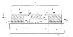
- FIG. 1 is a diagram schematically showing a cross section of a part of the measuring device 1 arranged in contact with the skin SK of the living body B.
- the measuring device 1 includes a sensor (measuring instrument) 11, a first thermal rectifying member (first member) 12, a second thermal rectifying member (second member) 13, an enclosure member (third member) 14, and an eaves. 15 is provided.
- the sensor 11 includes a heat flux sensor 110 and a temperature sensor 111.
- the heat flux sensor 110 and the temperature sensor 111 are housed inside the housing, for example.
- the heat flux sensor 110 is a sensor that detects heat transfer per unit area for a unit time, and measures the heat flux Hs [W / m 2] flowing into the sensor 11.
- the heat flux sensor 110 for example, a laminated structure, a plane expansion type actuating thermopile, or the like can be used.
- the temperature sensor 111 measures the epidermis temperature Ts, which is the temperature of the contact point with the living body B.
- Ts the temperature of the contact point with the living body B.
- a thermistor, a thermocouple, a platinum resistor, an IC temperature sensor, or the like can be used as the temperature sensor 111.
- the housing in which the sensor 11 houses the heat flux sensor 110 and the temperature sensor 111 is formed of, for example, a member which is circular in a plan view and has a disk-shaped outer shape.
- the housing included in the sensor 11 includes a lower surface (hereinafter, referred to as “lower surface of the sensor 11”) arranged in contact with the measurement surface of the skin SK and an upper surface in a direction away from the measurement surface of the skin SK (hereinafter, “sensor 11”). It is referred to as "the upper surface of 11").
- an opening is formed on the lower surface of the sensor 11, and the heat flux sensor 110 and the temperature sensor 111 are exposed from this opening.
- the first thermal rectifying member 12 is arranged on the side opposite to the side in contact with the surface of the skin SK of the living body B, which is the measurement surface to be measured, and is made of a material having a higher thermal conductivity than air. More specifically, the first thermal rectifying member 12 is arranged on the upper surface of the sensor 11 to relax the temperature distribution and the heat inflow distribution on the upper surface of the sensor 11 and to release heat from the sensor 11.
- the first thermal rectifying member 12 covers the entire upper surface of the sensor 11, for example, and has a thickness along the Z direction.
- the material of the first thermal rectifying member 12 can be made of a metal having a relatively large thermal conductivity.
- the first thermal rectifying member 12 has an increased cross-sectional area so that the thermal resistance value becomes smaller while increasing the surface area of the member.
- the above effect becomes greater when the first thermal rectifying member 12 is formed in a larger size.
- the measuring device 1 is designed to have a surface area and weight suitable for, for example, a wearable device to be mounted on the living body B, in which a lightweight design and miniaturization are realized, and heat rectification and release in the sensor 11 can be sufficiently obtained.
- the first thermal rectifying member 12 may have a structure having a uniform cross section along the Z direction and having a curvature only on the side surface.
- the inner core structure of the measuring device 1 is formed by the sensor 11 and the first thermal rectifying member 12. This inner core structure can promote heat transfer in the vertical direction (Z direction).
- the second thermal rectifying member 13 and the surrounding member 14 are arranged in contact with the measurement surface, and form a structure that surrounds the sensor 11 apart from the sensor 11.
- the second thermal rectifying member 13 is arranged in contact with the measurement surface (on the XY plane) and is made of a material having higher thermal conductivity than air. More specifically, as shown in FIG. 1, the second thermal rectifying member 13 is arranged apart from the sensor 11 on the measurement surface (on the XY plane) of the skin SK of the living body B. The second thermal rectifying member 13 is arranged on the measurement surface so as to surround the inner core structure composed of the sensor 11 and the first thermal rectifying member 12 with an interval ⁇ that does not come into contact with the sensor 11, for example. The distance ⁇ between the measurement surfaces between the second thermal rectifying member 13 and the sensor 11 forms a thermal gap between them.
- the second thermal rectifying member 13 is made of a material such as a metal having a relatively high thermal conductivity, and relaxes the distribution of heat inflow and outflow from the living body B.
- the width R along the measurement surface of the second thermal rectifying member 13 can be set to about 3 [mm]
- the thickness t along the Z direction can be set to about 1 [mm].
- the second thermal rectifying member 13 is a polymer. It is also possible to use a material having a relatively low thermal conductivity such as.
- the enclosure member 14 is arranged on the second thermal rectifying member 13 and surrounds the sensor 11.
- the enclosure member 14 has a lower surface and an upper surface, and the width of the lower surface along the measurement surface coincides with the width R of the second thermal rectifying member 13.
- the eaves 15 extend in the direction of the first thermal rectifying member 12 of the enclosure member 14.
- the eaves 15 are formed integrally with the enclosure member 14 by using the same material as the enclosure member 14.
- the length L of the upper surfaces of the enclosure member 14 and the eaves 15 has a preset length along the measurement surface.
- the enclosure member 14 and the eaves 15 are arranged on the measurement surface together with the second thermal rectifying member 13 so as to surround the sensor 11, and an outer peripheral ring surrounding the inner core structure composed of the sensor 11 and the first thermal rectifying member 12. Form a structure.
- the present embodiment is formed by the outer peripheral ring structure (structure) composed of the second thermal rectifying member 13, the enclosure member 14, and the eaves 15, and the distance ⁇ between the sensor 11 and the second thermal rectifying member 13.
- the resulting thermal gap suppresses lateral (measurement plane direction) heat transfer, or temperature gradient.
- the heights of the upper surfaces of the enclosure member 14 and the eaves 15 in the Z direction and the heights of the upper surfaces of the first thermal rectifying member 12 in the Z direction are equal to each other and separated from each other to the extent that they do not contact each other. And are arranged. It is desirable that the boundary layer is transferred between the enclosure member 14 and the eaves 15 and the first thermal rectifying member 12 without separating the air flow.
- the heat transfer coefficient h is the largest at the end face of the object, that is, the end faces of the enclosure member 14 and the eaves 15, but as shown in the following equation (6), L from the end face of the enclosure member 14.
- the heat transfer coefficient h decreases sharply in proportion to -2/3.
- the enclosure member 14 can be reduced in weight as a hollow structure.
- a polymer or the like may be used as the material of the enclosure member 14.
- the enclosure member 14 and the eaves 15 can be manufactured by a 3D printer or the like.
- the inner core structure formed by the sensor 11 and the first thermal rectifying member 12 and the outer peripheral ring structure (structure) formed by the second thermal rectifying member 13, the surrounding member 14 and the eaves 15 are shown in FIG.
- the positions may be maintained by a connection structure (not shown).
- the distance ⁇ between the sensor 11 and the second thermal rectifying member 13 is maintained by a sheet-shaped base material S (FIG. 3) arranged on the surface of the skin SK or another connection structure.
- the measuring device 1 includes a main part of the measuring device 1 described with reference to FIG. 1, an arithmetic circuit 100, a memory 101, a communication circuit 102, and a battery 103.
- the first thermal rectifying member 12, the second thermal rectifying member 13, the enclosure member 14, and the eaves 15 are omitted.
- the measuring device 1 powers the sensor 11, the arithmetic circuit 100, the memory 101, the communication circuit 102 functioning as an I / F circuit with the outside, the arithmetic circuit 100, the communication circuit 102, and the like.
- the battery 103 is provided.
- the calculation circuit 100 calculates an estimated value of core body temperature Tc from the heat flux Hs measured by the sensor 11 and the epidermis temperature Ts of the skin SK using the above equation (1). Further, the arithmetic circuit 100 may generate and output time-series data of the estimated core body temperature Tc of the living body B.
- the time-series data is data in which the measurement time and the estimated core body temperature Tc are associated with each other.
- the memory 101 stores information on a one-dimensional biological heat transfer model based on the above equation (1). Further, the memory 101 stores the thermal resistance value of the heat flux sensor 110.
- the memory 101 can be realized by a predetermined storage area in a rewritable non-volatile storage device (for example, a flash memory) provided in the measurement system.
- the communication circuit 102 outputs the time-series data of the core body temperature Tc of the living body B generated by the arithmetic circuit 100 to the outside.
- a communication circuit 102 is an output circuit to which a USB or other cable can be connected when outputting data or the like by wire.
- a wireless communication circuit compliant with Bluetooth (registered trademark), Bluetooth Low Energy, or the like. May be used.
- the sheet-shaped base material S functions as a base for mounting the measuring device 1 including the sensor 11, the arithmetic circuit 100, the memory 101, the communication circuit 102, and the battery 103, and electrically connects these elements. It is equipped with wiring (not shown). Considering that the measuring device 1 is connected to the epidermis of a living body, it is desirable to use a deformable flexible substrate for the sheet-shaped base material S.
- an opening is provided in a part of the sheet-shaped base material S, and the heat flux sensor 110 and the temperature sensor 111 included in the sensor 11 are placed on the base material S so as to be in contact with the measurement surface of the skin SK of the living body B from the opening. Placed.
- the measuring device 1 is realized by a computer. Specifically, the arithmetic circuit 100 processes various data according to a program stored in a storage device such as a ROM, a RAM, and a flash memory including a memory 101 in which a processor such as a CPU or a DSP is provided in the measuring device 1. It is realized by executing.
- the program for operating the computer as the measuring device 1 can be recorded on a recording medium or provided through a network.
- the measuring device 1 is integrally configured with the main part including the sensor 11 described with reference to FIG. 1 and another configuration including the arithmetic circuit 100.
- the main part of the measuring device 1 is The configuration may be separated from the arithmetic circuit 100, the memory 101, the communication circuit 102, and the battery 103.
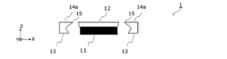
- FIG. 4 is a diagram schematically showing a cross section of a part of the measuring device 1 according to the specific example 1.
- the measuring device 1 includes a sensor 11, a first thermal rectifying member 12, a second thermal rectifying member 13, an enclosure member 14a, and an eaves 15.
- the shapes of the enclosure member 14a and the eaves 15 included in the measuring device 1 according to the specific example 1 are the same as the shapes of the enclosure member 14 and the eaves 15 described above, but are integrally formed of the same material as the second thermal rectifying member 13. ing.
- the enclosure member 14a, the eaves 15, and the second thermal rectifying member 13 are made of a material such as metal having a relatively high thermal conductivity.
- FIG. 5A is a view showing an external perspective view and a cross section of the measuring device 1 according to the specific example 1. Further, FIG. 5B shows a cross-sectional view of the measuring device 1 of FIG. 5A.
- the measuring device 1 includes a disk-shaped sensor 11 and a first thermal rectifying member 12, an annular second thermal rectifying member 13 surrounding the sensor 11 and a first thermal rectifying member 12 at regular intervals ⁇ , an enclosing member 14a, and an eaves. It is composed of 15.
- the second thermal rectifying member 13, the enclosure member 14a, and the eaves 15 can be manufactured into a torus-like structure by cutting aluminum.
- the first heat rectifying member 12 has a structure in which aluminum is cut to form a columnar shape and attached directly above the sensor 11 for measuring temperature and heat flux.
- FIG. 6 shows the measurement result of the core body temperature measured by using the measuring device 1 according to the specific example 1 shown in FIGS. 5A and 5B.
- the horizontal axis of FIG. 6 indicates the core body temperature [° C.]
- the vertical axis indicates the measured value [° C.].
- the three different markers in FIG. 6 indicate the wind speed, or convection, in the measurement environment, respectively. From FIG. 6, it can be seen that the measuring device 1 can measure the core body temperature without being affected by the change in convection.
- FIG. 7 is a diagram schematically showing a cross section of a part of the measuring device 1A according to the second embodiment.
- the measuring device 1A according to the second embodiment is different from the measuring device 1 according to the first embodiment in that the grid 16 is further provided.
- the lattice 16 has a porous structure, covers the upper surface of the first thermal rectifying member 12, and is formed between the ends of the upper surface of the enclosure member 14 and the eaves 15.
- the lattice 16 may be made of, for example, a material such as the same polymer as the enclosure member 14 and the eaves 15. Further, as the porous structure, a sheet-shaped mesh or the like can also be used.
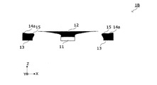
- FIG. 8A is a view showing an external perspective view of the measuring device 1B according to the third embodiment and a cross section thereof.
- FIG. 8B is a cross-sectional view of the measuring device 1B shown in FIG. 8A.
- the first thermal rectification is performed by increasing the diameter of the upper surface of the first thermal rectifying member 12 along the measurement surface as compared with the diameter of the upper surface of the sensor 11 along the measurement surface.
- the surface area of the member 12 can be increased.
- the length of the eaves 15 extending in the direction of the first thermal rectifying member 12 can be shorter than the length described in the first embodiment.
- the first thermal rectifying member 12 having the structures shown in FIGS. 8A and 8B can relax the temperature distribution and the heat inflow distribution on the upper surface of the sensor 11, and at the same time, can more efficiently release heat from the sensor 11. ..
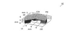
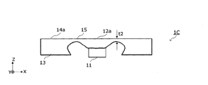
- FIG. 9A is a perspective view of the appearance of the measuring device 1C according to the fourth embodiment and a cross section thereof.
- the sensor 11 is omitted.
- the second thermal rectifying member 13 of the measuring device 1C, the surrounding member 14a, and the eaves 15 are integrally formed, and the eaves 15 are connected to the first thermal rectifying member 12a.
- the second thermal rectifying member 13, the enclosure member 14a, the eaves 15, and the first thermal rectifying member 12a can be formed of a material having high thermal conductivity such as aluminum.
- the thickness t2 of the eaves 15 along the Z direction is formed to be smaller than the thickness of the first thermal rectifying member 12a.
- the second thermal rectifying member 13, the enclosure member 14a, the eaves 15, and the first thermal rectifying member 12a can be integrally formed by using the same material.
- the first thermal rectifying member 12 arranged on the upper surface of the sensor 11 is provided apart from the sensor 11 along the measuring surface.
- the second thermal rectifying member 13 is provided, the enclosure member 14 arranged on the upper surface of the second thermal rectifying member 13, and the eaves 15 extending in the direction of the first thermal rectifying member 12 of the enclosure member 14. .. Therefore, the spatial distribution of heat inflow and outflow to the sensor 11 can be suppressed. As a result, the core body temperature of the living body can be measured non-invasively and more accurately.
- the measuring device 1 according to the first embodiment has a structure in which the upper surface of the first thermal rectifying member 12 and the upper surface of the enclosure member 14 and the eaves 15 are in direct contact with the outside air.
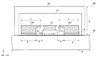
- the measuring device 1D according to the second embodiment further includes a plurality of covers 17 and 18.
- FIG. 10 is a diagram schematically showing a cross section of the measuring device 1D according to the present embodiment.
- the configurations of the measuring device 1D other than the covers 17 and 18 are the same as the configurations described in Specific Example 1 (FIGS. 4, 5A, 5B) of the first embodiment.
- the biot number Bi is known as a dimensionless number representing the ratio of heat transfer from the surface of a solid to heat conduction inside the solid.
- the biot number Bi is expressed by the following equation (7) and is used as an index of the stability of heat transfer.
- Bi hL / ⁇ ⁇ ⁇ ⁇ (7)
- ⁇ is the thermal conductivity
- h is the heat transfer coefficient
- L is the thickness of the living body.
- the biot number Bi when the biot number Bi is sufficiently smaller than 1, the heat conduction inside the solid is faster than that of heat transfer, so that the temperature distribution inside the object is almost uniform. Can be regarded.
- the biot number Bi if the biot number Bi is about 0.1, it can be approximated as a one-dimensional heat transfer model of a living body described by the above equation (1).
- the heat transfer coefficient h of the water constituting the living body B is h ⁇ 6 [W / m 2 K]
- the heat transfer coefficient h of the muscle is h ⁇ 4 [W / m]. 2 K]
- the heat transfer coefficient h of fat is about h ⁇ 1.8 [W / m 2 K].
- the thickness of the boundary layer is controlled from the above equation (6), and the measuring device 1D is in a state where the surrounding air does not move. It is necessary to make it almost windless.
- the first thermal rectifying member 12 and the first thermal rectifying member 12 and the first are arranged around the sensor 11 by the covers 17 and 18 having two hollow structures.
- the covers 17 and 18 are formed of a thin film such as a PET film, and the thickness of the film can be, for example, 100 [ ⁇ m].
- An air layer is formed between the sensor 11, the first thermal rectifying member 12, the second thermal rectifying member 13, the enclosure member 14a, and the eaves 15 and the cover 17 provided inside the cover 17. Further, the measuring device 1D is provided with another cover 18 on the outside of the cover 17, and an air layer is also formed between the inner cover 17 and the outer cover 18.
- the thickness ⁇ of the air layer, which is the boundary layer formed by the cover 18, in the Z direction can be, for example, about 6 [mm] or more.
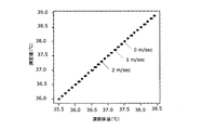
- FIG. 11 is a diagram showing measured values of core body temperature measured using the measuring device 1D according to the present embodiment.
- the vertical axis of FIG. 11 is the measured value (° C.), and the horizontal axis is the true value of the core body temperature (° C.).
- each marker indicates the wind speed of the outside air, that is, convection.
- the core body temperature of the living body can be measured more accurately even when the outside air blows. Recognize.
- the measuring device 1D according to the second embodiment, a small chamber of air separated by a plurality of covers 17 and 18 is formed, so that even if the measuring device 1D is exposed to wind. , The influence of the change in thermal resistance outside the sensor 11 can be suppressed. As a result, the core body temperature of the living body can be measured non-invasively and more accurately.
Landscapes
- Physics & Mathematics (AREA)
- General Physics & Mathematics (AREA)
- Chemical & Material Sciences (AREA)
- Engineering & Computer Science (AREA)
- Combustion & Propulsion (AREA)
- Measuring And Recording Apparatus For Diagnosis (AREA)
Abstract
Le dispositif de mesure (1) de l'invention est équipé : d'un capteur (11) possédant un capteur de température (110) et un capteur de flux thermique (111) ; d'un premier élément de rectification thermique (12) qui est placé sur le capteur (11) côté opposé à un côté en contact avec la surface de la peau (SK) d'un corps biologique (B), laquelle surface constitue une face de mesure objet de la mesure, et qui est constitué d'un matériau de conductivité thermique supérieure à celle de l'atmosphère ; et d'une structure qui est disposée en contact avec la face de mesure, et qui entoure le capteur (11) tout en étant éloignée de celui-ci.
Priority Applications (3)
| Application Number | Priority Date | Filing Date | Title |
|---|---|---|---|
| US17/913,397 US20230111956A1 (en) | 2020-04-01 | 2020-04-01 | Measurement Device |
| JP2022511439A JP7439906B2 (ja) | 2020-04-01 | 2020-04-01 | 測定装置 |
| PCT/JP2020/015026 WO2021199378A1 (fr) | 2020-04-01 | 2020-04-01 | Dispositif de mesure |
Applications Claiming Priority (1)
| Application Number | Priority Date | Filing Date | Title |
|---|---|---|---|
| PCT/JP2020/015026 WO2021199378A1 (fr) | 2020-04-01 | 2020-04-01 | Dispositif de mesure |
Publications (1)
| Publication Number | Publication Date |
|---|---|
| WO2021199378A1 true WO2021199378A1 (fr) | 2021-10-07 |
Family
ID=77927448
Family Applications (1)
| Application Number | Title | Priority Date | Filing Date |
|---|---|---|---|
| PCT/JP2020/015026 Ceased WO2021199378A1 (fr) | 2020-04-01 | 2020-04-01 | Dispositif de mesure |
Country Status (3)
| Country | Link |
|---|---|
| US (1) | US20230111956A1 (fr) |
| JP (1) | JP7439906B2 (fr) |
| WO (1) | WO2021199378A1 (fr) |
Families Citing this family (1)
| Publication number | Priority date | Publication date | Assignee | Title |
|---|---|---|---|---|
| US20250020522A1 (en) * | 2023-07-10 | 2025-01-16 | Apple Inc. | Electronic Devices With Temperature Sensors |
Citations (6)
| Publication number | Priority date | Publication date | Assignee | Title |
|---|---|---|---|---|
| JP2012073128A (ja) * | 2010-09-29 | 2012-04-12 | Terumo Corp | 体温計 |
| WO2013024568A1 (fr) * | 2011-08-18 | 2013-02-21 | テルモ株式会社 | Thermomètre clinique |
| JP2013044624A (ja) * | 2011-08-24 | 2013-03-04 | Terumo Corp | 体温計 |
| WO2016143529A1 (fr) * | 2015-03-12 | 2016-09-15 | オムロン株式会社 | Appareil de mesure de température interne et boîtier de capteur |
| JP2018151322A (ja) * | 2017-03-14 | 2018-09-27 | オムロン株式会社 | 内部温度測定装置 |
| JP2020003291A (ja) * | 2018-06-27 | 2020-01-09 | 日本電信電話株式会社 | 生体内温度測定装置および生体内温度測定方法 |
Family Cites Families (20)
| Publication number | Priority date | Publication date | Assignee | Title |
|---|---|---|---|---|
| JPS5923369B2 (ja) * | 1979-01-26 | 1984-06-01 | 昭和電工株式会社 | 零位法熱流計 |
| SU1223065A1 (ru) * | 1984-03-07 | 1986-04-07 | Специальное Конструкторское Бюро Института Органической Химии Им.Н.Д.Зелинского | Тепловой расходомер |
| JPH0629799B2 (ja) * | 1985-06-17 | 1994-04-20 | 京都電子工業株式会社 | 放散熱量測定装置 |
| JPH0760107B2 (ja) * | 1989-07-11 | 1995-06-28 | 三菱電機株式会社 | 熱式流量センサの信号処理方法 |
| US5803915A (en) * | 1995-12-07 | 1998-09-08 | Ohmeda Inc. | System for detection of probe dislodgement |
| US6095679A (en) * | 1996-04-22 | 2000-08-01 | Ta Instruments | Method and apparatus for performing localized thermal analysis and sub-surface imaging by scanning thermal microscopy |
| JP4095362B2 (ja) * | 2002-07-12 | 2008-06-04 | 株式会社堀場エステック | 流量計 |
| JP4600170B2 (ja) * | 2004-09-15 | 2010-12-15 | セイコーエプソン株式会社 | 体温計、および体温計を有する電子機器 |
| DE102007002369B3 (de) * | 2007-01-17 | 2008-05-15 | Drägerwerk AG & Co. KGaA | Doppeltemperatursensor |
| US8573843B2 (en) * | 2010-11-05 | 2013-11-05 | Citizen Holdings Co., Ltd. | Temperature measuring device |
| DE102013007631A1 (de) * | 2013-05-02 | 2014-11-06 | Dräger Medical GmbH | Verfahren und Vorrichtung zur Bestimmung einer Kerntemperatur eines Körpers |
| JP6349713B2 (ja) | 2013-12-13 | 2018-07-04 | オムロン株式会社 | 内部温度センサ |
| DE102015206938A1 (de) * | 2015-04-17 | 2016-10-20 | Robert Bosch Gmbh | Vorrichtung und Verfahren zum Messen einer Körpertemperatur eines Lebewesens |
| US10866147B2 (en) * | 2015-12-21 | 2020-12-15 | Koninklijke Philips N.V. | Heat-flow sensor |
| JP7151607B2 (ja) * | 2019-04-19 | 2022-10-12 | 日本電信電話株式会社 | 温度測定装置および温度測定方法 |
| US20230255496A1 (en) * | 2020-07-13 | 2023-08-17 | Nippon Telegraph And Telephone Corporation | Measurement Device |
| CN112656384A (zh) * | 2020-12-22 | 2021-04-16 | 浙江大学 | 一种核心温度测量探头、系统及方法 |
| US20240353271A1 (en) * | 2021-12-16 | 2024-10-24 | Nippon Telegraph And Telephone Corporation | Temperature measurement device |
| KR20230119810A (ko) * | 2022-02-08 | 2023-08-16 | 삼성전자주식회사 | 체온 추정 장치 및 방법 |
| KR20240138343A (ko) * | 2023-03-10 | 2024-09-20 | 삼성전자주식회사 | 열유속 센서 및 그 열유속 센서를 이용한 심부 체온 추정 방법 |
-
2020
- 2020-04-01 WO PCT/JP2020/015026 patent/WO2021199378A1/fr not_active Ceased
- 2020-04-01 US US17/913,397 patent/US20230111956A1/en not_active Abandoned
- 2020-04-01 JP JP2022511439A patent/JP7439906B2/ja active Active
Patent Citations (6)
| Publication number | Priority date | Publication date | Assignee | Title |
|---|---|---|---|---|
| JP2012073128A (ja) * | 2010-09-29 | 2012-04-12 | Terumo Corp | 体温計 |
| WO2013024568A1 (fr) * | 2011-08-18 | 2013-02-21 | テルモ株式会社 | Thermomètre clinique |
| JP2013044624A (ja) * | 2011-08-24 | 2013-03-04 | Terumo Corp | 体温計 |
| WO2016143529A1 (fr) * | 2015-03-12 | 2016-09-15 | オムロン株式会社 | Appareil de mesure de température interne et boîtier de capteur |
| JP2018151322A (ja) * | 2017-03-14 | 2018-09-27 | オムロン株式会社 | 内部温度測定装置 |
| JP2020003291A (ja) * | 2018-06-27 | 2020-01-09 | 日本電信電話株式会社 | 生体内温度測定装置および生体内温度測定方法 |
Also Published As
| Publication number | Publication date |
|---|---|
| JPWO2021199378A1 (fr) | 2021-10-07 |
| US20230111956A1 (en) | 2023-04-13 |
| JP7439906B2 (ja) | 2024-02-28 |
Similar Documents
| Publication | Publication Date | Title |
|---|---|---|
| JP7444241B2 (ja) | 測定装置 | |
| RU2489690C2 (ru) | Структура датчика температуры | |
| KR20090097153A (ko) | 심부 온도를 측정하기 위한 디바이스 | |
| CN109632144B (zh) | 一种用于确定生物核心温度的测量探头 | |
| JP6398808B2 (ja) | 内部温度測定装置及びセンサパッケージ | |
| JP7151607B2 (ja) | 温度測定装置および温度測定方法 | |
| JP4805773B2 (ja) | 電子温度計 | |
| WO2020109119A1 (fr) | Système de capteur de température corporelle centrale basé sur une mesure de flux | |
| WO2016143518A1 (fr) | Appareil de mesure de différence de température | |
| JP2015169551A (ja) | 深部温度計 | |
| WO2021199378A1 (fr) | Dispositif de mesure | |
| JP5956063B2 (ja) | 内部温度測定方法及び接触式内部温度計 | |
| JP2013044624A (ja) | 体温計 | |
| JP7424495B2 (ja) | 測定装置 | |
| JP2018151322A (ja) | 内部温度測定装置 | |
| JP7464137B2 (ja) | 測定装置 | |
| JP7367878B2 (ja) | 測定装置 | |
| JP7639939B2 (ja) | 温度測定装置 | |
| CN209559366U (zh) | 一种用于确定生物核心温度的测量探头 | |
| JP7586340B2 (ja) | 温度測定装置 | |
| JP7593494B2 (ja) | 温度推定システムおよび温度推定方法 | |
| JP7586341B2 (ja) | 測定装置 | |
| WO2021240717A1 (fr) | Procédé et système de détermination d'état d'installation | |
| JP6428397B2 (ja) | 内部温度測定装置及び温度差測定モジュール | |
| JP2025169041A (ja) | 計測装置、計測方法、及び、制御プログラム |
Legal Events
| Date | Code | Title | Description |
|---|---|---|---|
| 121 | Ep: the epo has been informed by wipo that ep was designated in this application |
Ref document number: 20929144 Country of ref document: EP Kind code of ref document: A1 |
|
| ENP | Entry into the national phase |
Ref document number: 2022511439 Country of ref document: JP Kind code of ref document: A |
|
| NENP | Non-entry into the national phase |
Ref country code: DE |
|
| 122 | Ep: pct application non-entry in european phase |
Ref document number: 20929144 Country of ref document: EP Kind code of ref document: A1 |