WO2021199975A1 - Procédé et système de thérapie - Google Patents
Procédé et système de thérapie Download PDFInfo
- Publication number
- WO2021199975A1 WO2021199975A1 PCT/JP2021/009427 JP2021009427W WO2021199975A1 WO 2021199975 A1 WO2021199975 A1 WO 2021199975A1 JP 2021009427 W JP2021009427 W JP 2021009427W WO 2021199975 A1 WO2021199975 A1 WO 2021199975A1
- Authority
- WO
- WIPO (PCT)
- Prior art keywords
- light
- irradiation
- tumor cells
- optical device
- duct
- Prior art date
- Legal status (The legal status is an assumption and is not a legal conclusion. Google has not performed a legal analysis and makes no representation as to the accuracy of the status listed.)
- Ceased
Links
Images



Classifications
-
- A—HUMAN NECESSITIES
- A61—MEDICAL OR VETERINARY SCIENCE; HYGIENE
- A61N—ELECTROTHERAPY; MAGNETOTHERAPY; RADIATION THERAPY; ULTRASOUND THERAPY
- A61N5/00—Radiation therapy
- A61N5/06—Radiation therapy using light
- A61N5/0613—Apparatus adapted for a specific treatment
- A61N5/062—Photodynamic therapy, i.e. excitation of an agent
-
- A—HUMAN NECESSITIES
- A61—MEDICAL OR VETERINARY SCIENCE; HYGIENE
- A61N—ELECTROTHERAPY; MAGNETOTHERAPY; RADIATION THERAPY; ULTRASOUND THERAPY
- A61N5/00—Radiation therapy
- A61N5/06—Radiation therapy using light
- A61N5/0601—Apparatus for use inside the body
-
- A—HUMAN NECESSITIES
- A61—MEDICAL OR VETERINARY SCIENCE; HYGIENE
- A61B—DIAGNOSIS; SURGERY; IDENTIFICATION
- A61B5/00—Measuring for diagnostic purposes; Identification of persons
- A61B5/0059—Measuring for diagnostic purposes; Identification of persons using light, e.g. diagnosis by transillumination, diascopy, fluorescence
- A61B5/0071—Measuring for diagnostic purposes; Identification of persons using light, e.g. diagnosis by transillumination, diascopy, fluorescence by measuring fluorescence emission
-
- A—HUMAN NECESSITIES
- A61—MEDICAL OR VETERINARY SCIENCE; HYGIENE
- A61B—DIAGNOSIS; SURGERY; IDENTIFICATION
- A61B5/00—Measuring for diagnostic purposes; Identification of persons
- A61B5/43—Detecting, measuring or recording for evaluating the reproductive systems
- A61B5/4306—Detecting, measuring or recording for evaluating the reproductive systems for evaluating the female reproductive systems, e.g. gynaecological evaluations
- A61B5/4312—Breast evaluation or disorder diagnosis
-
- A—HUMAN NECESSITIES
- A61—MEDICAL OR VETERINARY SCIENCE; HYGIENE
- A61B—DIAGNOSIS; SURGERY; IDENTIFICATION
- A61B5/00—Measuring for diagnostic purposes; Identification of persons
- A61B5/48—Other medical applications
- A61B5/4836—Diagnosis combined with treatment in closed-loop systems or methods
-
- A—HUMAN NECESSITIES
- A61—MEDICAL OR VETERINARY SCIENCE; HYGIENE
- A61N—ELECTROTHERAPY; MAGNETOTHERAPY; RADIATION THERAPY; ULTRASOUND THERAPY
- A61N5/00—Radiation therapy
- A61N5/06—Radiation therapy using light
- A61N5/0601—Apparatus for use inside the body
- A61N2005/0612—Apparatus for use inside the body using probes penetrating tissue; interstitial probes
-
- A—HUMAN NECESSITIES
- A61—MEDICAL OR VETERINARY SCIENCE; HYGIENE
- A61N—ELECTROTHERAPY; MAGNETOTHERAPY; RADIATION THERAPY; ULTRASOUND THERAPY
- A61N5/00—Radiation therapy
- A61N5/06—Radiation therapy using light
- A61N2005/063—Radiation therapy using light comprising light transmitting means, e.g. optical fibres
Definitions
- the present invention relates to a therapeutic method and a therapeutic device for destroying tumor cells.
- breast-conserving therapy has a great advantage in that it can improve the quality of life of the patient.
- local recurrence after breast-conserving treatment is currently seen in 10 to 20%. For this reason, the satisfaction level of local treatment in breast-conserving therapy is not yet high.
- a treatment method using a photoreactive substance is known as a method for destroying target cells such as tumor cells.
- the treatment method using an antibody-photosensitive substance hydrophilic phthalocyanine
- excitation light for example, near infrared rays
- Only the target cell can be specifically destroyed without destroying the target cell. Therefore, this therapeutic method is expected to obtain a high therapeutic effect while minimizing side effects.
- an immune reaction is evoked through fragments of destroyed cells, and thus a therapeutic effect due to its own immune function is also expected. If local treatment using such a photoreactive substance can be applied to breast cancer patients, it is expected that a high therapeutic effect can be obtained while preserving the breast.
- Patent Document 1 describes a device that can be inserted into a breast duct to burn a lesion. Since this device destroys not only the lesion but also normal cells, the burden on the living body is large.
- the present invention has been made to solve the above-mentioned problems, and provides a treatment method and a treatment system capable of treating while confirming the degree of destruction of tumor cells by irradiation with light and improving the therapeutic effect.
- the purpose is a treatment method and a treatment system capable of treating while confirming the degree of destruction of tumor cells by irradiation with light and improving the therapeutic effect.
- the treatment method according to the present invention that achieves the above object is a treatment method in which a photosensitizer accumulated in a breast cancer tumor cell is irradiated with excitation light, and the photosensitizer is injected into a blood vessel, a breast duct, or a lymphatic vessel.
- the step of administration the step of inserting an optical device having an optical fiber from the opening of the breast tube into the breast tube, the step of irradiating the photosensitive substance accumulated in the tumor cells with the excitation light, and the step of irradiating the excitation light. It comprises a step of detecting the fluorescence emitted by the light-sensitive substance, and the step of irradiating and / or the step of detecting the light is performed by an optical device inserted in the breast tube.
- the treatment method constructed as described above effectively irradiates the photosensitizer accumulated in the tumor cells of breast cancer with excitation light and / or detects fluorescence by using an optical device inserted near the tumor cells. Can be done. Therefore, in this treatment method, the degree of destruction of tumor cells by irradiation with excitation light can be confirmed by detecting fluorescence, and the therapeutic effect can be improved.
- the excitation light is near infrared rays
- the optical device has an irradiation unit capable of irradiating near infrared rays and a detection unit capable of detecting external light
- the step of irradiating the excitation light is performed by the irradiation unit.
- the step of detecting the fluorescence emitted by the light-sensitive substance may be performed by the detection unit.
- the step of comparing the fluorescence intensity detected by the detection unit with the threshold value and the position of the irradiation unit capable of irradiating near infrared rays are changed when or after the fluorescence intensity reaches the threshold value.
- the treatment method can treat the degree of destruction of tumor cells by irradiation with near infrared rays while confirming with high accuracy by comparing the fluorescence intensity with the threshold value. Therefore, this treatment method can further improve the therapeutic effect.
- the treatment method before the step of irradiating the excitation light, while changing the position of the irradiation portion, the fluorescence emitted by the photosensitive substance irradiated with near infrared rays is detected, and the position and fluorescence of the fluorescence are emitted. It may have a step of checking the strength. As a result, this treatment method can effectively destroy breast cancer tumor cells with as few tumor cells as possible after accurately grasping the distribution of the tumor cells.
- the treatment method may include a step of expanding the tip of the optical device inserted into the duct and arranging the irradiation portion and / or the detection portion in the vicinity of the inner wall of the duct.
- the breast in the step of irradiating the excitation light and the step of detecting the fluorescence, the breast is deformed so as to be thin, and the light-sensitive substance accumulates at the position of the irradiation portion and / or the detection portion. It may be brought closer to the tumor cells. This makes it possible to effectively irradiate the light-sensitive substance with near-infrared rays from the irradiation unit and / or detect the fluorescence emitted by the light-sensitive substance.
- a catheter for acquiring a tomographic image is inserted into the duct from the opening of the duct before the step of irradiating the excitation light, and a tomographic image of a tissue containing tumor cells in which the photosensitive substance is accumulated is obtained. It may have a step to acquire.
- this treatment method can effectively destroy breast cancer tumor cells with as few tumor cells as possible after accurately grasping the distribution of the tumor cells.
- a fluorescent reagent having an excitation wavelength different from that of the photosensitive substance and capable of emitting fluorescence having a wavelength different from the fluorescence emitted by the photosensitive substance is administered intravascularly, intraductally or intralymphally. It may have a step of irradiating the tumor cell with light having an excitation wavelength of the fluorescent reagent and detecting the fluorescence emitted by the fluorescent reagent accumulated in the tumor cell. Even if the photosensitizer causes a photoreaction and does not fluoresce, the fluorescent reagent can fluoresce, so the operator can tell that the photoreaction of the photosensitizer promoted the destruction of tumor cells. It can be easily recognized by the fluorescence emitted by.
- the photosensitizer may contain an antibody-photosensitizer bound to an antibody that accumulates in tumor cells.
- the antibody bound to the photosensitizer improves the accumulation of the photosensitizer in the tumor cell, so that the tumor cell can be destroyed more reliably.
- the treatment system according to the present invention that achieves the above object is a treatment system that irradiates a photosensitizer accumulated in breast cancer tumor cells with excitation light, and propagates light between the proximal end and the distal end. It is provided with an optical fiber capable of being capable of being provided, and has an optical device having an irradiation unit capable of irradiating light to the outside and a detection unit capable of detecting external light at the tip portion. It is characterized in that it can be inserted into.
- the irradiation part and the detection part of the optical device can be arranged at a position close to the tumor cells in the breast duct, and the light-sensitive substance accumulated in the tumor cells can be effectively irradiated with the excitation light. , Fluorescence emitted by light-sensitive substances accumulated in tumor cells can be effectively detected. Therefore, the treatment system can perform treatment while confirming the degree of destruction of tumor cells by irradiation with excitation light by detecting fluorescence, and can improve the therapeutic effect.
- the treatment system has an analyzer connected to a base end portion of the optical device to receive and analyze the light detected by the detection unit, and the analyzer calculates the intensity of fluorescence received from the detection unit. Then, when the intensity of the fluorescence is below the threshold value or below the threshold value, a threshold value arrival signal indicating that the fluorescence intensity is below the threshold value or below the threshold value may be output. This allows the treatment system to notify the operator that the fluorescence intensity is below or below the threshold, or to stop the irradiation of excitation light.
- the tip portion of the optical device has an expansion portion that can expand and contract in the radial direction, and the irradiation portion and the detection portion may be arranged in the expansion portion.
- the irradiation part and the detection part can be arranged in the vicinity of the inner wall of the milk duct by expanding the expansion part in the milk duct. Therefore, the influence of the body fluid in the breast tube that hinders the arrival of light can be reduced, and the photosensitive substance accumulated in the tumor cells can be effectively irradiated with the excitation light from the irradiation portion, and the photosensitive substance accumulated in the tumor cells can be effectively irradiated. Fluorescence emitted by can be effectively detected.
- the photosensitizer may include an antibody-photosensitizer bound to an antibody that accumulates in tumor cells.
- the antibody bound to the photosensitizer improves the accumulation of the photosensitizer in the tumor cell, so that the tumor cell can be destroyed more reliably.
- the treatment system 10 is used for photoimmunotherapy in which a photosensitive substance accumulated on the cell membrane of a target cell is irradiated with near infrared rays to destroy the target cell.
- the target cell is a tumor cell such as a cancer cell.
- an antibody-photosensitizer in which an antibody that specifically accumulates only on a specific antigen on the surface of a tumor cell and a photosensitizer paired with the antibody are bound is used as a drug.
- the antibody is not particularly limited, and examples thereof include panitumbab, trastuzumab, HuJ591, pertuzumab, lapatinib, palbociclib, and olaparib.
- Photosensitive substances are, for example, hydrophilic phthalocyanines (IR700) that react with near-infrared rays having a wavelength of about 700 nm and hydrophilic phthalocyanines (IR800) that react with near-infrared rays having a wavelength of about 789 to 794 nm, but are limited thereto. Not done.
- IR700 hydrophilic phthalocyanines
- IR800 hydrophilic phthalocyanines
- the membrane protein is extracted, a hole is opened in the cell membrane, and water enters the cell, so that the cancer cell can be ruptured and destroyed.
- the IR700 is excited by receiving near infrared rays and emits fluorescence having a wavelength different from the excitation wavelength. For example, the IR700 emits fluorescence with a wavelength of 700 to 705 nm when excited by receiving near infrared rays with a wavelength of 689 nm.
- the IR700 changes its structure while emitting fluorescence by a photoreaction, and when it destroys tumor cells and plays a role as a drug, it does not emit fluorescence.
- the treatment system 10 irradiates the antibody-photosensitive substance accumulated in the tumor cells with near infrared rays and detects the change in fluorescence emitted by the antibody-photosensitive substance to detect the light of the antibody-photosensitive substance. It measures in real time that tumor cells are destroyed by the reaction. Note that real-time is not limited to being performed exactly at the same time, and detection of changes in fluorescence intensity emitted by an antibody-photosensitive substance may be performed in parallel with near-infrared irradiation with a slight time lag. , Is a broad concept that means repeating irradiation and detection at short intervals of several seconds or less.
- the time difference may be a time lag caused by communication, calculation, or the like, or a set or calculated value.
- the treatment system 10 does not have to measure in real time if it can measure that the tumor cells are destroyed by the photoreaction of the antibody-photosensitive substance during the treatment.
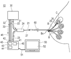
- the treatment system 10 analyzes an optical device 20 that irradiates and detects light in the milk duct B, a light source device 30 that supplies light to the optical device 20, and the detected light. It is provided with an analyzer 40 for performing analysis and a display device 50 for displaying the analysis result.
- the light source device 30 has an output unit 31 capable of outputting near infrared rays of an arbitrary wavelength with an arbitrary intensity (power) and energy, and a reference light output unit 32 that outputs the same light as the output unit 31 as reference light.
- the output unit 31 is connected to the optical device 20.
- the reference optical output unit 32 is connected to the analyzer 40.
- the light source device 30 outputs light to the optical device 20 so that light having a wavelength of, for example, 660 to 740 nm and an energy of, for example, 1 to 50 Jcm-2 can be emitted from the optical device 20.
- the optical device 20 includes a shaft portion 21 inserted into the milk duct B, an input cable 22 connected to the light source device 30, an output cable 23 connected to the analyzer 40, and an optical circulator 24.
- the base end of the input cable 22 can be connected to the output unit 31 of the light source device 30, and the tip of the input cable 22 is connected to the optical circulator 24.
- the input cable 22 has at least one optical fiber that propagates light, and propagates the light received from the output unit 31 to the optical circulator 24.
- the base end of the output cable 23 can be connected to the analyzer 40, and the tip of the output cable 23 is connected to the optical circulator 24.
- the output cable 23 has at least one optical fiber that propagates light, and propagates the light received from the optical circulator 24 to the analyzer 40.
- the shaft portion 21 includes at least one optical fiber 27 that propagates light.
- the base end portion of the shaft portion 21 is connected to the optical circulator 24.
- the tip portion of the shaft portion 21 includes an irradiation unit 25 that irradiates light to the outside and a detection unit 26 that detects external light.
- Each of the shaft portion 21, the input cable 22, and the output cable 23 may be composed of one fiber or a plurality of bundled fibers.
- the optical circulator 24 propagates the light received from the input cable 22 to the shaft portion 21. Further, the optical circulator 24 propagates the light received from the shaft portion 21 to the output cable 23.
- the optical device 20 does not have to include the optical circulator 24.
- the shaft portion 21 includes a plurality of optical fibers 27, the optical fiber 27 connected to the irradiation portion 25 of the shaft portion 21 is connected to the input cable 22, and the optical fiber 27 connected to the detection portion 26 of the shaft portion 21 is output. It may be connected to the cable 23.
- the irradiation unit 25 irradiates the light propagated from the proximal end side to the distal end side via the optical fiber 27 to the outside.
- the irradiation unit 25 may be composed of, for example, a structure in which the cut stump of the optical fiber 27 is exposed, a structure in which the surface coating is peeled off, a lens, a diffuser, a mirror, or the like.
- the irradiation unit 25 is appropriately designed so that it can irradiate near infrared rays in a predetermined direction at a predetermined irradiation angle.
- the structure of the irradiation unit 25 is not limited as long as it can irradiate light to the outside.
- the irradiation direction of the irradiation unit 25 (the direction in which the center of the irradiation angle is located) is not particularly limited.
- the irradiation direction of the irradiation unit 25 may be the tip direction of the shaft portion 21 or a direction substantially orthogonal to the axial center of the shaft portion 21.
- the detection unit 26 receives external light into the optical fiber 27 and detects the light.
- the light that has entered the inside of the optical fiber 27 is propagated to the proximal end side of the optical fiber 27.
- the detection unit 26 may be composed of, for example, a structure in which the surface coating of the optical fiber 27 is peeled off, a lens, a diffuser, a mirror, or the like.
- the detection unit 26 may have a structure common to that of the irradiation unit 25. That is, the detection unit 26 may be the irradiation unit 25.
- the analyzer 40 is a device that monitors during treatment that near-infrared rays are acting on tumor C having tumor cells. Monitoring is done in real time, but it does not have to be done in real time.
- the analyzer 40 includes a detection light input unit 41 that receives the light detected by the detection unit 26 of the optical device 20, and a reference light input unit 42 that receives the reference light from the reference light output unit 32 of the light source device 30. ..
- the output cable 23 of the optical device 20 is connected to the detection optical input unit 41.
- the reference optical cable 33 connected to the reference light output unit 32 of the light source device 30 is connected to the reference light input unit 42.
- the analyzer 40 can receive light from the output cable 23 of the optical device 20, analyze the intensity of light of each wavelength, and monitor the destruction of tumor cells in which antibody-photosensitive substances are accumulated.
- the analyzer 40 includes a photoelectric conversion unit 43, a storage unit 44, and a storage unit 44, which, as a physical configuration of hardware, convert light into an electric signal after passing through a filter that spectroscopically extracts light at each wavelength or selectively extracts only a specific wavelength. It includes a processing unit 45.
- the storage unit 44 is, for example, a semiconductor memory element such as a RAM (Random Access Memory) or a flash memory (Flash Memory), or a hard disk, an optical disk or the like.
- the storage unit 44 can write or read the fluorescence threshold value T, the program, or the like, which will be described later, depending on the processing status.
- the processing unit 45 is, for example, a CPU (Central Processing Unit), an MPU (Micro Processing Unit), or the like.
- the processing unit 45 can perform arithmetic processing by executing, for example, a RAM as a work area for a program stored in the storage unit 44.
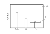
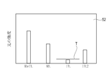
- the processing unit 45 monitors the change in the intensity of the fluorescent FL at the wavelength emitted by the antibody-photosensitive substance that has received near infrared rays, and when the intensity of the fluorescent FL becomes equal to or less than the threshold T or less than the threshold T, FIG. As shown in 3, the operator is notified via the display device 50.
- the processing unit 45 controls the light source device 30 via the connection cable 46 connected to the analyzer 40, and outputs the light source device 30.
- the light output from the unit 31 may be stopped or reduced.
- the processing unit 45 calculates the intensity of the reference light RefL input to the reference light input unit 42.
- the processing unit 45 has the intensity of the reflected light RL having the same wavelength as the irradiation light (the same wavelength as the reference light RefL) and the wavelength different from the reference light RefL and the reflected light RL from the light input to the detection light input unit 41.
- the intensity of the fluorescent FL having The processing unit 45 can transmit a signal representing the calculated result to the display device 50 and display it on the display panel 52 described later.
- the display device 50 is connected to the analyzer 40 by a display cable 51.
- the display device 50 receives a display signal from the analyzer 40 via the display cable 51, and the display panel 52 can display information for notifying the operator.
- the display device 50 may include a sound output unit (speaker) for notifying the operator by sound.
- the operator administers the antibody-photosensitizer intravascularly, intraductally B, or intralymphatically.
- the operator administers it intravenously or intraarterally.
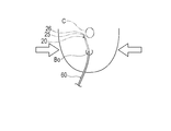
- the operator places a known guide wire (not shown) in the vicinity of the tumor C shown in FIG. 2 approximately 12 to 36 hours after the administration. Insert into the duct opening Bo that can reach B.
- the proximal end of the guide wire is inserted into the lumen of the catheter 60 (eg, a microcatheter), and the catheter 60 is inserted into the duct B through the duct opening Bo along the guide wire. After this, the operator removes the guide wire from the catheter 60.
- the operator waits until the antibody-photosensitive substance accumulates on the target cell membrane.
- the time until the antibody-photosensitive substance accumulates on the target cell membrane is shorter than that in the case of intravenous administration. For example, it is considered to be about 5 to 10 minutes.
- the operator inserts the shaft portion 21 of the optical device 20 into the catheter 60 from the proximal end side of the catheter 60.
- the tip of the optical device 20 projects from the catheter 60 toward the tip.
- the operator makes the tip of the optical device 20 reach the target position while checking, for example, under ultrasonic fluoroscopy.
- the target position is a position close to the tumor C and capable of irradiating the tumor C with near infrared rays.
- the target position may be directly visually recognized from the body surface, and a high-sensitivity camera can be used. It may be detected and confirmed.
- the surgeon confirms the treatment preparation, the treatment position, the setting of the threshold value T, and the like. Therefore, the operator operates the analyzer 40 that controls the light source device 30 to output near infrared rays from the light source device 30 (step S10).
- the light source device 30 outputs near infrared rays having a wavelength of, for example, 689 nm from the output unit 31 and the reference light output unit 32 with a predetermined intensity (power).
- the reference light RefL output from the reference light output unit 32 is input to the reference light input unit 42 of the analyzer 40.
- the near infrared rays output from the output unit 31 of the light source device 30 pass through the input cable 22, the optical circulator 24 and the shaft unit 21, and are directed toward the tumor C from the irradiation unit 25 arranged at the tip of the shaft unit 21. Is irradiated.
- the detection unit 26 arranged at the tip of the shaft unit 21 detects light from the outside.
- the detection unit 26 is an irradiation light (or reflected light RL) emitted by a reflected light RL having the same wavelength as the near infrared rays (irradiation light) emitted from the irradiation unit 25 and an antibody-photosensitive substance excited by receiving the near infrared rays.
- a fluorescent FL (700 to 705 nm) having a wavelength different from that of) is detected.
- the light detected by the detection unit 26 is input to the detection light input unit 41 of the analyzer 40 through the shaft unit 21, the optical circulator 24, and the output cable 23.
- the processing unit 45 of the analyzer 40 receives the signals of the reference light RefL, the reflected light RL, and the fluorescence FL (step S11).
- the processing unit 45 of the analyzer 40 calculates the intensity of the reference light RefL received by the reference light input unit 42 and the intensities of the reflected light RL and the fluorescent FL received by the detection light input unit 41 in real time (step S12). ..
- the processing unit 45 displays the calculated intensities of the reference light RefL, the reflected light RL, and the fluorescent FL on the display panel 52 of the display device 50 in real time (step S13).
- the operator moves the position of the irradiation unit 25 while looking at the display panel 52, and measures the intensity and distribution of the fluorescent FL.
- the operator can operate the analyzer 40 to input the threshold value T (step S14).
- the processing unit 45 of the analyzer 40 sets the input value as the threshold value T (step S15).
- the threshold T is a predetermined absolute value to be set, or is the ratio of the intensity of the fluorescent FL to the intensity of the reference light RefL, or the ratio of the intensity of the detected fluorescent FL to the intensity of the reflected light RL. May be good.
- the threshold value T may be set in advance instead of being input by the operator during the procedure.
- the surgeon determines the treatment procedure for tumor C (eg, division into multiple treatment sites or threshold T).
- the surgeon holds the irradiation unit 25 at a position where the near-infrared ray can be irradiated to the site to be treated at the beginning of the tumor C, operates the analyzer 40, and starts the treatment (step S16).
- the processing unit 45 starts measuring the irradiation time (step S17).
- the antibody-photosensitive substance accumulated in the tumor cells When the antibody-photosensitive substance accumulated in the tumor cells is irradiated with near infrared rays, the antibody-photosensitive substance causes a photoreaction to emit fluorescent FL and destroy the tumor cells.
- the antibody-photosensitive substance does not emit fluorescent FL after destroying the tumor cells. Therefore, by measuring the change in the intensity of the detected fluorescent FL in real time, it is possible to confirm the progress state of the photoreaction that destroys the tumor cells.
- the processing unit 45 of the analyzer 40 displays the calculated intensities of the reference light RefL, the reflected light RL, and the fluorescence FL on the display panel 52 of the display device 50 in real time as shown in FIG. 3 (step). S13).
- the ratio of the reflected light RL to the reference light RefL is substantially constant. Therefore, only one of the reference light RefL and the reflected light RL may be measured.
- the processing unit 45 determines whether the detected fluorescent FL intensity is less than the set threshold value T (or less than or equal to the threshold value T) (step S18).
- the processing unit 45 determines that the intensity of the fluorescent FL is not less than the threshold value T (or the threshold value T or less).
- the processing unit 45 considers that the progress of the photoreaction that destroys the tumor cells is insufficient, and the near-infrared rays from the light source device 30 The output is continued, and the process returns to step S11.
- the processing unit 45 determines that the intensity of the fluorescent FL is less than the threshold value T (or less than or equal to the threshold value T)
- it determines that the photoreaction that destroys the tumor cells has been sufficiently performed.
- the processing unit 45 outputs a threshold value arrival signal indicating that the intensity of the fluorescence FL is less than the threshold value T (or the threshold value T or less), transmits the threshold value arrival signal to the display device 40, and displays the display panel in real time. It is displayed on 52 (step S19).
- the intensity of the fluorescent FL is less than the threshold value T (or the threshold value T or less) is that the light reaction proceeds after sufficient irradiation, and the fluorescent RL is caused by foreign matter such as body fluid invading the irradiated part. May not be detected. Therefore, the operator or the processing unit 45 may start irradiation of near infrared rays from the light source device 30 after confirming that the illumination RefL, the reflected light RL, and the fluorescence FL have a certain relationship.
- the processing unit 45 When the relationship between the reference light RefL and the reflected light RL does not change and the fluorescence FL decreases during the irradiation of the near infrared rays, the processing unit 45 stably proceeds with the irradiation of the near infrared rays and the photoreaction. Judge. Further, when the reflected light RL or the reflected light RL and the fluorescent FL are significantly reduced with respect to the reference light RefL during the irradiation of near infrared rays, the processing unit 45 determines that the irradiation state has been changed by the foreign matter. The processing unit 45 can transmit the determined result to the display device 40 and display it on the display panel 52. In this way, the detection result of the reflected light RL may be used in order to determine that stable near-infrared irradiation for the photoreaction is being performed.
- the processing unit 45 determines whether or not the irradiation time after the start of near-infrared output is equal to or greater than the preset minimum irradiation time (step S20).
- the minimum irradiation time is the minimum irradiation time set to ensure the minimum irradiation amount. Therefore, after starting the output of near infrared rays from the light source device 30, the processing unit 45 does not stop the irradiation until the irradiation time becomes (or exceeds) the minimum irradiation time or more.
- the processing unit 45 determines that the irradiation time does not exceed (or does not exceed) the minimum irradiation time, the processing unit 45 continues the output of near infrared rays from the light source device 30 and returns to step S02. Then, when the processing unit 45 determines that the irradiation time has exceeded (or exceeded) the minimum irradiation time, information indicating that the condition for completing the treatment (irradiation of near infrared rays) at the treatment site has been satisfied. Is displayed on the display device 50 in real time (step S21). This completes the treatment of the initially selected treatment site.
- the minimum irradiation time does not have to be set.
- the processing unit 45 determines in step S18 that the intensity of the fluorescent FL is less than the threshold value T (or less than or equal to the threshold value T)
- the processing unit 45 stops the output of near infrared rays without performing steps S15 to S16.
- Information indicating that the conditions to be satisfied is satisfied is displayed on the display device 50 in real time (step S21).
- step S21 there may be a function of displaying that the condition for stopping the output is satisfied and temporarily stopping the output. When the output is temporarily stopped, the light source is stopped or at least a part of the optical path including the input cable 22 is blocked.
- Step S22 when ending the treatment of the selected treatment site, the operator can operate the analyzer 40 to select whether to treat another site of the tumor C or to end the treatment of the tumor C.
- the surgeon shifts and moves the irradiation unit 25 to a position where the next treatment site can be irradiated with near-infrared rays.
- the surgeon begins treatment of the new treatment site (step S16).
- the operator measures the change in the intensity of the fluorescent FL in real time, and performs the treatment with near infrared rays until the condition for completing the treatment is satisfied (step S21). This allows the surgeon to sequentially treat a plurality of treatment sites.
- the surgeon treats all the treatment sites of the tumor C, and if it determines that there are no other treatment sites, operates the analyzer 40 to select whether to end the treatment of the tumor C (step S22).
- the processing unit 45 stops the output of near infrared rays from the light source device 30 (step S23). In this way, the surgeon can destroy the tumor cells distributed in a wide range by alternately repeating the movement of the position of the irradiation unit 25 and the treatment of destroying the tumor cells by the photoreaction.
- the operator removes the optical device 20 and the catheter 60 from the duct B to complete the procedure.
- the processing unit 45 stops the irradiation of the near infrared rays each time the treatment of each selected treatment site is completed, and starts the irradiation of the near infrared rays each time the treatment of each selected treatment site is started. You may let me.
- the tip of the optical device 20 may be curved and shaped so that it is directed in any direction within the duct B.
- a wire-shaped protrusion may be formed at the tip of the optical device 20 so as to be easily oriented in the milk duct B.
- the operator when performing the treatment, the operator may deform the irradiation unit 25 and / or the detection unit 26 by sandwiching the breast so as to bring it closer to the tumor C.
- the direction in which the breast is sandwiched can be determined from the measurement results of the intensity and distribution of the entire fluorescent FL of the tumor C performed before the treatment.
- the treatment system 10 is the treatment system 10 that irradiates the antibody-photosensitive substance accumulated in the tumor cells in the breast cancer tumor cells with excitation light, and is a proximal end portion.
- An optical device 20 having an optical fiber 27 capable of propagating light between the and the tip portion, and having an irradiation unit 25 capable of irradiating light to the outside and a detection unit 26 capable of detecting external light at the tip portion.
- the tip of the optical device 20 can be inserted into the duct B through the duct opening Bo.
- the irradiation unit 25 and the detection unit 26 of the optical device 20 are arranged at positions close to the tumor cells in the breast tube B, and are close to the antibody-photosensitive substance accumulated in the tumor cells. Infrared rays can be effectively irradiated, and fluorescent FL emitted by antibody-light sensitive substances accumulated in tumor cells can be effectively detected. Therefore, the treatment system 10 can perform treatment while confirming the degree of destruction of tumor cells by irradiation with near infrared rays by detecting fluorescent FL, and can improve the therapeutic effect.
- the treatment system 10 has an analyzer 40 which is connected to the base end portion of the optical device 20 and receives and analyzes the light detected by the detection unit 26, and the analyzer 40 has a fluorescent FL received from the detection unit 26.
- the intensity of the fluorescent FL is equal to or less than the threshold value T or less than the threshold value T
- a threshold value arrival signal indicating that the intensity is equal to or less than the threshold value T or less than the threshold value T is output.
- the treatment system 10 can notify the operator that the intensity of the fluorescent FL is equal to or less than the threshold value T or less than the threshold value T, or can stop the irradiation of the excitation light.
- the treatment method in the present embodiment is a treatment method in which the antibody-photosensitive substance accumulated in the tumor cells of breast cancer is irradiated with excitation light, and the antibody-photosensitive substance is intravascularly, intraductally or intraductally.
- An optical device having a step of irradiating and a step of detecting fluorescent FL emitted by an antibody-photosensitive substance irradiated with excitation light, and a step of irradiating and / or detecting the step. 20 is performed.
- the therapeutic method constructed as described above is effective in irradiating the antibody-photosensitive substance accumulated in the tumor cells of breast cancer with excitation light and / or detecting fluorescent FL by an optical device 20 inserted near the tumor cells. Can be done Therefore, in this treatment method, the degree of destruction of tumor cells by irradiation with excitation light can be confirmed in real time by detecting fluorescent FL, and the therapeutic effect can be improved.
- the excitation light is near infrared rays
- the optical device 20 has an irradiation unit 25 capable of irradiating near infrared rays and a detection unit 26 capable of detecting external light
- the step of irradiating the excitation light is the irradiation unit 25.
- the step of detecting the fluorescence emitted by the antibody-photosensitive substance may be performed by the detection unit 26.
- the treatment method includes a step of comparing the intensity of the fluorescent FL detected by the detection unit 26 with the threshold value T, and an irradiation unit capable of irradiating near infrared rays when or after the intensity of the fluorescent FL reaches the threshold value T. It has a step of changing the position of 25 or stopping the irradiation of near infrared rays.
- this treatment method can treat the degree of destruction of tumor cells by irradiation with near infrared rays while confirming the degree of destruction of tumor cells with high accuracy by comparing the intensity of fluorescent FL with the threshold value T. Therefore, this treatment method can further improve the therapeutic effect.
- the treatment method before the step of irradiating the excitation light, while changing the position of the irradiation unit 25, the fluorescent FL emitted by the antibody-photosensitive substance irradiated with near infrared rays is detected, and the position where the fluorescent FL is emitted is detected. And has a step of confirming the intensity of the fluorescent FL.
- this treatment method can effectively destroy breast cancer tumor cells with as few tumor cells as possible after accurately grasping the distribution of the tumor cells.
- the breast in the step of irradiating the excitation light and the step of detecting the fluorescent FL, the breast is deformed so as to be thin, and the position of the irradiation unit 25 and / or the detection unit 26 is determined by the antibody-photosensitive substance. It may be brought closer to the accumulated tumor cells. This makes it possible to effectively irradiate the antibody-photosensitive substance with excitation light from the irradiation unit 25 and / or detect the fluorescent FL emitted by the antibody-photosensitive substance.
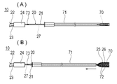
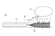
- the treatment system 10 according to the second embodiment has, as shown in FIGS. It differs from the first embodiment in that it has a sheath 71 that can be contracted and accommodated.
- the shaft portion 21 is connected to the tip portion with an expansion portion 70 that can be expanded and contracted in the radial direction (direction perpendicular to the axis of the shaft portion 21).
- the expansion portion 70 is formed in a mesh shape by a light guide body capable of propagating light.
- the base end portion of the expansion portion 70 is connected to the shaft portion 21, and the tip end portion of the expansion portion 70 is widened so as to have an outer diameter larger than the outer diameter of the shaft portion 21 in a natural state where no external force acts. .. That is, in the natural state, the expansion portion 70 is formed in a cylindrical shape so that the inner diameter and the outer diameter expand toward the tip side while having a gap due to the mesh shape.
- the expansion portion 70 is knitted so that a plurality of thin wire rods 72 have a gap, and the plurality of wire rods 72 are connected at the tip portion of the expansion portion 70 so as not to be unraveled.
- the expansion portion 70 has a structure in which the radial force is not applied to the inner wall of the milk duct B as much as possible during expansion. As a result, the burden on the milk duct B due to the expansion of the expansion portion 70 can be reduced. For this reason, the material forming the expansion portion 70 is formed of, for example, a highly elastic rubber material or a thin and flexible thread-like member.
- At least one of the plurality of wire rods 72 forming the expansion portion 70 may be an optical fiber 27 extending from the shaft portion 21 to supply near infrared rays.
- the optical fiber 27 forming at least a part of the expansion unit 70 includes at least one irradiation unit 25 and a detection unit 26 in the axial direction of the optical fiber 27.
- the optical fiber 27 forming at least a part of the expansion portion 70 may have a plurality of irradiation portions 25 arranged in the axial direction of the optical fiber 27, or an irradiation portion 25 formed long in the axial direction.
- the optical fiber 27 forming at least a part of the expansion unit 70 may have a plurality of detection units 26 arranged in the axial direction of the optical fiber 27 and a detection unit 26 formed long in the axial direction.
- a position marker 73 is arranged at the base end portion of the optical device 20 (for example, the base end portion of the shaft portion 21) so as to coincide with the circumferential positions of the irradiation portion 25 and the detection portion 26 of the expansion portion 70. Has been done.
- the position marker 73 is used by the operator to grasp the circumferential positions of the irradiation unit 25 and the detection unit 26, which are inserted into the breast duct B and cannot be seen by the operator.
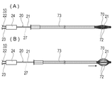
- the sheath 71 is a cylindrical member capable of accommodating the shaft portion 21 and the expansion portion 70. As shown in FIG. 6A, the sheath 71 moves in the distal direction with respect to the shaft portion 21 and the expansion portion 70, thereby contracting the expansion portion 70 in the radial direction and accommodating the sheath 71. The sheath 71 moves from the state in which the expansion portion 70 is housed to the shaft portion 21 and the expansion portion 70 in the proximal direction, thereby releasing the expansion portion 70 as shown in FIG. 6 (B). As a result, the expansion portion 70 is restored to its original expanded shape by its own elastic force.
- the operator inserts the optical device 20 into the duct opening in a state where the expansion portion 70 is housed in the sheath 71 as shown in FIG. 6 (A). Insert from Bo into milk duct B. After this, as shown in FIGS. 6B and 7, the operator moves the sheath 71 toward the proximal end and releases the expansion portion 70 from the sheath 71.
- the expansion portion 70 expands by its own restoring force and comes into contact with the inner wall of the milk duct B or is arranged near the inner wall of the milk duct B.
- An irradiation unit 25 and a detection unit 26 are arranged in the expansion unit 70. Therefore, since near-infrared rays can be irradiated in the vicinity of the inner wall of the milk duct B, it is possible to suppress the influence of the body fluid in the milk duct B, which hinders the arrival of light, on the irradiation of light. Therefore, near-infrared rays can be effectively applied to the antibody-photosensitive substance accumulated in the tumor cells.
- the detection unit 26 can effectively detect the reflected light RL of near infrared rays and the fluorescent FL emitted by the antibody-photosensitive substance.
- the body fluid in the milk duct B can flow through the gaps of the mesh-shaped expansion portion 70. Therefore, the expansion portion 70 is likely to expand without being hindered by the body fluid and come into contact with the inner wall of the milk duct B, or to be located near the inner wall of the milk duct B.
- the operator can orient the positions of the irradiation unit 25 and the detection unit 26 in the circumferential direction by confirming the position of the position marker 73 at the proximal end portion of the optical device 20.
- the treatment system 10 has an expansion unit 70 that can be expanded and contracted in the radial direction at the tip of the optical device 20, and the irradiation unit 25 and the detection unit 26 are expansion units. It is arranged at 70. As a result, by expanding the expansion unit 70 in the milk duct B, the irradiation unit 25 and the detection unit 26 can be arranged in the vicinity of the inner wall of the milk duct B.
- the influence of the body fluid in the milk duct B that hinders the arrival of light can be reduced, and the antibody-photosensitive substance accumulated in the tumor cells can be effectively irradiated with near-infrared rays from the irradiation unit 25, and the antibody-light sensitivity can be effectively irradiated. Fluorescent FL emitted by a substance can be effectively detected.
- the treatment method in the second embodiment includes a step of expanding the tip portion of the optical device 20 inserted into the milk duct B and arranging the irradiation unit 25 and / or the detection unit 26 in the vicinity of the inner wall of the milk duct B.
- the irradiation unit 25 irradiates the antibody-photosensitive substance with near infrared rays and / or detects the fluorescent FL emitted by the antibody-photosensitive substance. Can be done effectively.
- the structure of the expansion unit 70 is not particularly limited.
- the expansion portion 70 is in a state in which a plurality of slit-shaped through holes penetrating from the outer peripheral surface to the inner peripheral surface are formed in a circular tube as a material by laser processing or the like, and the tip portion is expanded outward in the radial direction. It may be a so-called self-expandable stent-like member shaped by.
- the optical fiber 27 having the irradiation unit 25 and the detection unit 26 is fixed so as to be wound around the expansion unit 70.
- the expansion portion 70 is formed of a light guide body that is not an optical fiber, and can receive near infrared rays from the optical fiber 27 forming the shaft portion 21 and irradiate the outside, and can receive light from the outside and propagate the light to the optical fiber 27. It may be a structure.
- the expansion portion 70 may include an outer tube 73 for accommodating the shaft portion 21 including the optical fiber 27, as in the modified example shown in FIG.
- the tip end portion of the expansion portion 70 including the plurality of wire rods 72 is fixed to the tip end portion of the shaft portion 21, and the base end portion of the expansion portion 70 is fixed to the tip end portion of the outer pipe 73.
- the expansion portion 70 is a light guide connected to the optical fiber 27 forming the shaft portion 21, or is a part of the optical fiber 27.
- the operator can apply a compressive force in the axial direction to the expansion portion 70 by moving the outer tube 73 toward the tip of the shaft portion 21.
- the expansion portion 70 can be expanded outward in the radial direction.
- the operator can contract the expansion portion 70 inward in the radial direction as shown in FIG. 8A by moving the outer tube 73 with respect to the shaft portion 21 in the proximal direction.
- the expansion portion may be a wire rod wound in a spiral shape (coil shape) of one or a plurality of wires, a balloon that expands by inflowing a fluid, or the like.
- the treatment system 10 separately includes a first optical device 80 including an irradiation unit 25 and a second optical device 90 including a detection unit 26. It is different from the first embodiment.
- the first optical device 80 has a first shaft portion 81 provided with an optical fiber 27 that receives near infrared rays from the output portion 31 of the light source device 30, and irradiates the tip portion of the first shaft portion 81 with near infrared rays.
- the irradiation unit 25 to be used is arranged.
- the second optical device 90 has a second shaft portion 91 provided with an optical fiber 27 that propagates light to the detection light input portion 41 of the analyzer 40, and is externally attached to the tip of the second shaft portion 91.
- a detection unit 26 for detecting reflected light RL and fluorescent FL is provided.
- the operator inserts the first shaft portion 81 into the duct B through the duct opening Bo, and the irradiation portion 25 is accumulated in the tumor cells. Place the antibody-photosensitive substance in a position where it can irradiate near infrared rays. After that, the operator inserts the second shaft portion 91 through the duct opening Bo and inserts the second shaft portion 91 into a duct B different from the duct B in which the irradiation portion 25 is arranged. Next, the operator arranges the detection unit 26 at a position where fluorescent FL from tumor cells irradiated with near infrared rays can be detected.
- the operator operates the analyzer 40 that controls the light source device 30, irradiates near infrared rays from the irradiation unit 25, and detects the reflected light RL and the fluorescent FL by the detection unit 26. This allows the operator to measure the change in the intensity of the detected fluorescent FL in real time and confirm the progress of the photoreaction that destroys the tumor cells.
- the first optical device 80 including the irradiation unit 25 is inserted into the breast duct B, and the second optical device 80 including the detection unit 26 is provided.
- the optical device 90 may be placed on the skin such as the breast outside the body.
- the second optical device 90 including the detection unit 26 is inserted into the milk duct B, and the first optical device 80 including the irradiation unit 25 is arranged on the skin such as the breast outside the body. May be good.
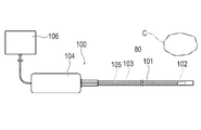
- the optical device 100 of the treatment system 10 detects reflected light and forms a tomographic image of a living tissue by optical coherence tomography (OCT). It may be.
- the optical device 100 is arranged in the long outer tube 101, the scanning unit 102 which is an irradiation unit for irradiating light and a detection unit for detecting light, and the outer tube 101, which are arranged in the outer tube 101.
- a drive shaft 103 that rotationally drives the scanning unit 102, a drive source 104 that applies a rotational force to the drive shaft 103, and a scanning unit 102 that is arranged inside the drive shaft 103 and rotates together with the drive shaft 103.
- It has an optical fiber 105 and a control unit 106 connected to the optical fiber 105 to create a tomographic image.
- the control unit 106 includes a light source device and an analyzer.
- the control unit 106 controls the drive source 104 to rotate the drive shaft 103 and the scanning unit 102. Then, the control unit 106 can irradiate the scanning unit 102 with light and detect the reflected light to create an all-around tomographic image surrounding the optical device 100.
- the control unit 106 This allows the operator to grasp the position and distribution of the tumor C from the tomographic image obtained from the OCT catheter 60. Then, the operator causes the control unit 106 to output near infrared rays from the scanning unit 102, which is the irradiation unit, and detect the reflected light RL and the fluorescent FL from the scanning unit 102, which is the detection unit. This allows the surgeon to measure in real time that tumor cells are destroyed by the photoreaction of antibody-photosensitive substances using an OCT catheter that forms a tomographic image. At this time, since the scanning unit 102, which is the irradiation unit and the detection unit, rotates, the near infrared rays can be output all around the optical device 100, and the light can be detected all around.
- the optical device 100 can effectively destroy a wide range of tumor cells.
- the scanning unit 102 does not have to rotate. Further, the scanning unit 102 may be able to acquire a wide range of three-dimensional images in the axial direction and destroy a wide range of tumor cells by moving inside the outer tube 101 in the axial direction while rotating. ..
- an outer tube so that the antibody-photosensitive substance accumulated in the tumor cells can be effectively irradiated with near-infrared rays from the scanning unit 102, and the fluorescent FL emitted by the antibody-light-sensitive substance can be effectively detected by the scanning unit 102. It is preferable that 101 is in close contact with the milk duct B. For this reason, it is preferable that the outer diameter of the outer tube 101 is slightly larger than the inner diameter of the milk duct B, or that the extinguishing son is inserted into the milk duct B in advance before inserting the outer tube 101.
- an ultrasonic (IVUS) catheter may be inserted into the duct B instead of an OCT catheter.
- Ultrasound catheters can acquire tomographic images deeper than OCT catheters. Since the ultrasonic catheter is not detected by irradiating light, it is used in combination with the optical device 20 or the like of the treatment system 10 according to the first to third embodiments.
- a thicker son or a liquid-filled balloon may be placed on the surface of the ultrasonic catheter.
- a catheter for acquiring a tomographic image is inserted from the duct opening Bo into the duct before the step of irradiating near infrared rays, and an antibody-photosensitive substance is accumulated. It has the step of acquiring a tomographic image of the tissue containing the tumor cells.
- this treatment method can effectively destroy breast cancer tumor cells with as few tumor cells as possible after accurately grasping the distribution of the tumor cells.
- a fluorescent reagent having an excitation wavelength different from that of the target antibody-photosensitive substance may also be used in advance in a blood vessel, in a duct B, or in a duct B. It may be administered intralymphically.
- the timing and location of administration of the fluorescent reagent may be the same as or different from that of the antibody-photosensitive substance.
- fluorescent reagents are accumulated in the tumor cells. Indocyanine green is excited by, for example, light having a wavelength of 774 nm to emit fluorescent FL2 having a wavelength of 805 nm.
- the irradiation unit 25 includes near-infrared light having a wavelength that excites the antibody-photosensitive substance (for example, 689 nm) and light having a wavelength that excites a fluorescent reagent different from the antibody-photosensitive substance (for example, 774 nm). Irradiate light.
- the processing unit 45 has a reference light RefL (for example, a wavelength of 689 nm), a reflected light RL having the same wavelength as the near infrared rays emitted from the irradiation unit 25 (for example, a wavelength of 689 nm), and a tumor cell.
- the intensity of the fluorescent FL (for example, wavelength 704 nm) emitted by the antibody-photosensitive substance accumulated in the tumor cell and the fluorescent FL2 (for example, wavelength 805 nm) emitted by the fluorescent reagent accumulated in the tumor cells are calculated and displayed on the display device 50. Can be done.
- the antibody-photosensitive substance does not emit fluorescent FL when it receives near infrared rays and causes a photoreaction to destroy tumor cells. Therefore, it becomes difficult to identify the site where the tumor cells were located by the fluorescent FL. On the other hand, even if the antibody-photosensitive substance causes a photoreaction, the fluorescent reagent does not undergo a chemical change, so that it can emit fluorescent FL2.
- photosensitive substances such as 5-aminolevulinic acid (ALA), Photofrin (Porfimer sodium), and rezaphyrin are administered in advance, and excitation light is directed toward tumor cells.
- Photodynamic therapy (PDT) may be performed.
- a fluorescent reagent having an excitation wavelength different from that of the antibody-photosensitive substance and capable of emitting fluorescent FL2 having a wavelength different from that of the fluorescent FL emitted by the antibody-photosensitive substance is used in the blood vessel.
- the step of administering into the breast tube B or the lymphatic vessel, and the step of irradiating the tumor cells with light of the excitation wavelength of the fluorescent reagent to detect the fluorescent FL2 emitted by the fluorescent reagent accumulated in the tumor cells. good. Even if the antibody-photosensitive substance causes a photoreaction and does not emit fluorescent FL, the fluorescent reagent emits fluorescent FL2, so the operator can tell that the photoreaction of the antibody-photosensitive substance has promoted the destruction of tumor cells. , It can be easily recognized by the fluorescent FL2 emitted by the fluorescent reagent.
- Treatment system 20 100 Optical device 25 Irradiation unit 26 Detection unit 27 Optical fiber 30
- Light source device 40 Analyzer 50
- Display device 70 Expansion unit 80
- First optical device (optical device) 81 First shaft part 90
- Second optical device (optical device) 91
- Second shaft part 102
- Scanning part (irradiation part, detection part) 105
- Optical fiber 106
- Control unit (light source device, analyzer) B duct Bo duct opening C tumor FL antibody-fluorescence emitted by a photosensitizer FL2 fluorescence emitted by a fluorescent reagent RefL reference light RL reflected light
Landscapes
- Health & Medical Sciences (AREA)
- Life Sciences & Earth Sciences (AREA)
- Engineering & Computer Science (AREA)
- Biomedical Technology (AREA)
- Public Health (AREA)
- Pathology (AREA)
- Veterinary Medicine (AREA)
- Animal Behavior & Ethology (AREA)
- General Health & Medical Sciences (AREA)
- Nuclear Medicine, Radiotherapy & Molecular Imaging (AREA)
- Radiology & Medical Imaging (AREA)
- Biophysics (AREA)
- Physics & Mathematics (AREA)
- Heart & Thoracic Surgery (AREA)
- Medical Informatics (AREA)
- Molecular Biology (AREA)
- Surgery (AREA)
- Radiation-Therapy Devices (AREA)
- Investigating, Analyzing Materials By Fluorescence Or Luminescence (AREA)
Abstract
Un procédé et un système de thérapie, par lesquels une thérapie peut être réalisée tout en confirmant le degré de destruction de cellules tumorales qui peut être provoquée par l'irradiation avec de la lumière et l'effet de la thérapie peut être amélioré, sont divulgués. L'invention concerne également un système de thérapie (10) pour irradier une substance sensible à la lumière accumulée dans une cellule tumorale du cancer du sein avec une lumière d'excitation, le système de thérapie (10) étant équipé d'un dispositif optique (20) qui est pourvu d'une fibre optique (27) qui peut propager la lumière entre une partie d'extrémité de base et une partie d'extrémité de pointe et qui est également pourvue, au niveau de la partie d'extrémité de pointe de celle-ci, d'une unité d'irradiation (25) qui peut émettre de la lumière vers l'extérieur et d'une unité de détection (26) qui peut détecter la lumière à l'extérieur, dans laquelle la partie d'extrémité de pointe du dispositif optique (20) peut être insérée dans un conduit de sein (B) à travers une ouverture de conduit de sein (Bo).
Priority Applications (4)
| Application Number | Priority Date | Filing Date | Title |
|---|---|---|---|
| CN202180024208.5A CN115335117A (zh) | 2020-03-30 | 2021-03-10 | 治疗方法及治疗系统 |
| JP2022511740A JP7675701B2 (ja) | 2020-03-30 | 2021-03-10 | 治療システム |
| US17/933,507 US20230008437A1 (en) | 2020-03-30 | 2022-09-20 | Treatment Method and Treatment System |
| JP2025074054A JP2025107251A (ja) | 2020-03-30 | 2025-04-28 | 治療システム |
Applications Claiming Priority (2)
| Application Number | Priority Date | Filing Date | Title |
|---|---|---|---|
| JP2020059473 | 2020-03-30 | ||
| JP2020-059473 | 2020-03-30 |
Related Child Applications (1)
| Application Number | Title | Priority Date | Filing Date |
|---|---|---|---|
| US17/933,507 Continuation US20230008437A1 (en) | 2020-03-30 | 2022-09-20 | Treatment Method and Treatment System |
Publications (1)
| Publication Number | Publication Date |
|---|---|
| WO2021199975A1 true WO2021199975A1 (fr) | 2021-10-07 |
Family
ID=77929055
Family Applications (1)
| Application Number | Title | Priority Date | Filing Date |
|---|---|---|---|
| PCT/JP2021/009427 Ceased WO2021199975A1 (fr) | 2020-03-30 | 2021-03-10 | Procédé et système de thérapie |
Country Status (4)
| Country | Link |
|---|---|
| US (1) | US20230008437A1 (fr) |
| JP (2) | JP7675701B2 (fr) |
| CN (1) | CN115335117A (fr) |
| WO (1) | WO2021199975A1 (fr) |
Cited By (1)
| Publication number | Priority date | Publication date | Assignee | Title |
|---|---|---|---|---|
| WO2024166416A1 (fr) * | 2023-02-06 | 2024-08-15 | 国立大学法人東海国立大学機構 | Procédé d'évaluation de l'efficacité thérapeutique d'une photo-immunothérapie proche infrarouge |
Families Citing this family (1)
| Publication number | Priority date | Publication date | Assignee | Title |
|---|---|---|---|---|
| DE102020117579A1 (de) * | 2020-07-03 | 2022-01-05 | Hoya Corporation | Endoskopisches Beleuchtungssystem für ein Fluoreszenzmittel |
Citations (5)
| Publication number | Priority date | Publication date | Assignee | Title |
|---|---|---|---|---|
| JP2008194084A (ja) * | 2007-02-08 | 2008-08-28 | Fujikura Ltd | 光ファイバ、光ファイバ装置及びバンドルファイバ |
| WO2012128326A1 (fr) * | 2011-03-23 | 2012-09-27 | 国立大学法人筑波大学 | Nanoparticules pour une thérapie photodynamique |
| US20170050043A1 (en) * | 2014-04-18 | 2017-02-23 | Yukyong National University Industry-University Cooperation Foundation | Probe comprising optically diffusing fiber, method for manufacturing same and applications thereof |
| JP2017071654A (ja) * | 2011-07-11 | 2017-04-13 | ザ ユナイテッド ステイツ オブ アメリカ, アズ リプレゼンテッド バイ ザ セクレタリー, デパートメント オブ ヘルス アンド ヒューマン サービシーズ | 光増感抗体−蛍光団コンジュゲート |
| JP2019092532A (ja) * | 2017-11-17 | 2019-06-20 | 学校法人早稲田大学 | 生体埋め込み型の無線給電型発光システム |
Family Cites Families (5)
| Publication number | Priority date | Publication date | Assignee | Title |
|---|---|---|---|---|
| US6846311B2 (en) * | 2002-04-02 | 2005-01-25 | Acueity, Inc. | Method and apparatus for in VIVO treatment of mammary ducts by light induced fluorescence |
| JP5736116B2 (ja) * | 2010-03-15 | 2015-06-17 | ソニー株式会社 | 算出装置 |
| US10674918B2 (en) * | 2012-01-06 | 2020-06-09 | The Florida International University Board Of Trustees | Near-infrared (NIR) optical scanner |
| KR20130126374A (ko) * | 2012-05-11 | 2013-11-20 | 삼성전자주식회사 | 유방암 진단을 위한 광 간섭 단층촬영 장치 및 이의 제어 방법 |
| DE102014016850B9 (de) * | 2014-11-13 | 2017-07-27 | Carl Zeiss Meditec Ag | Optisches System zur Fluoreszenzbeobachtung |
-
2021
- 2021-03-10 WO PCT/JP2021/009427 patent/WO2021199975A1/fr not_active Ceased
- 2021-03-10 CN CN202180024208.5A patent/CN115335117A/zh active Pending
- 2021-03-10 JP JP2022511740A patent/JP7675701B2/ja active Active
-
2022
- 2022-09-20 US US17/933,507 patent/US20230008437A1/en not_active Abandoned
-
2025
- 2025-04-28 JP JP2025074054A patent/JP2025107251A/ja active Pending
Patent Citations (5)
| Publication number | Priority date | Publication date | Assignee | Title |
|---|---|---|---|---|
| JP2008194084A (ja) * | 2007-02-08 | 2008-08-28 | Fujikura Ltd | 光ファイバ、光ファイバ装置及びバンドルファイバ |
| WO2012128326A1 (fr) * | 2011-03-23 | 2012-09-27 | 国立大学法人筑波大学 | Nanoparticules pour une thérapie photodynamique |
| JP2017071654A (ja) * | 2011-07-11 | 2017-04-13 | ザ ユナイテッド ステイツ オブ アメリカ, アズ リプレゼンテッド バイ ザ セクレタリー, デパートメント オブ ヘルス アンド ヒューマン サービシーズ | 光増感抗体−蛍光団コンジュゲート |
| US20170050043A1 (en) * | 2014-04-18 | 2017-02-23 | Yukyong National University Industry-University Cooperation Foundation | Probe comprising optically diffusing fiber, method for manufacturing same and applications thereof |
| JP2019092532A (ja) * | 2017-11-17 | 2019-06-20 | 学校法人早稲田大学 | 生体埋め込み型の無線給電型発光システム |
Cited By (1)
| Publication number | Priority date | Publication date | Assignee | Title |
|---|---|---|---|---|
| WO2024166416A1 (fr) * | 2023-02-06 | 2024-08-15 | 国立大学法人東海国立大学機構 | Procédé d'évaluation de l'efficacité thérapeutique d'une photo-immunothérapie proche infrarouge |
Also Published As
| Publication number | Publication date |
|---|---|
| US20230008437A1 (en) | 2023-01-12 |
| CN115335117A (zh) | 2022-11-11 |
| JPWO2021199975A1 (fr) | 2021-10-07 |
| JP2025107251A (ja) | 2025-07-17 |
| JP7675701B2 (ja) | 2025-05-13 |
Similar Documents
| Publication | Publication Date | Title |
|---|---|---|
| US11583694B2 (en) | Treatment method | |
| US20090240154A1 (en) | Combined oct catheter device and method for combined optical coherence tomography (oct) diagnosis and photodynamic therapy (pdt) | |
| JP2025107251A (ja) | 治療システム | |
| KR20000015834A (ko) | 컬럼부에 빛을 조사하는, 개선된 광역학 요법 및 장치 | |
| EP2666516A1 (fr) | Appareil de thérapie laser, système de thérapie laser et procédé d'évaluation | |
| WO2008080121A1 (fr) | Milieux fluides pour applications biosensibles | |
| US20040267335A1 (en) | Switched photodynamic therapy apparatus and method | |
| CN115802928A (zh) | 通过光声信号分析的斑块切除术引导 | |
| US20210379395A1 (en) | Treatment Method and Treatment System | |
| WO2021066012A1 (fr) | Dispositif d'irradiation et méthode de traitement | |
| JP2006167046A (ja) | 癌治療状況評価方法および装置ならびに癌治療方法および装置 | |
| US20230085299A1 (en) | Treatment apparatus and treatment method | |
| KR102755939B1 (ko) | 벌룬 카테터를 이용한 식도 질환 광 치료 장치 및 방법 | |
| JP2022075134A (ja) | 光照射デバイス、及び、光照射システム | |
| US20210379396A1 (en) | Treatment method and treatment system | |
| US12527969B2 (en) | Treatment method and treatment system | |
| WO2021044627A1 (fr) | Procédé d'irradiation de cellules par de la lumière | |
| KR101924492B1 (ko) | 의료용 광조사 및 모니터링 장치 | |
| US12048508B2 (en) | Direct in-vivo tumor imaging using optical applicator | |
| JP2023140728A (ja) | 医療デバイス | |
| JP2024017698A (ja) | 医療デバイス、医療システム並びに、診断および治療方法 | |
| JPH0394776A (ja) | 体内留置用導光装置 | |
| JPH04166169A (ja) | アテローム除去装置 |
Legal Events
| Date | Code | Title | Description |
|---|---|---|---|
| 121 | Ep: the epo has been informed by wipo that ep was designated in this application |
Ref document number: 21780556 Country of ref document: EP Kind code of ref document: A1 |
|
| ENP | Entry into the national phase |
Ref document number: 2022511740 Country of ref document: JP Kind code of ref document: A |
|
| NENP | Non-entry into the national phase |
Ref country code: DE |
|
| 122 | Ep: pct application non-entry in european phase |
Ref document number: 21780556 Country of ref document: EP Kind code of ref document: A1 |