WO2021199999A1 - Dispositif d'équilibrage et d'équilibreur - Google Patents
Dispositif d'équilibrage et d'équilibreur Download PDFInfo
- Publication number
- WO2021199999A1 WO2021199999A1 PCT/JP2021/009666 JP2021009666W WO2021199999A1 WO 2021199999 A1 WO2021199999 A1 WO 2021199999A1 JP 2021009666 W JP2021009666 W JP 2021009666W WO 2021199999 A1 WO2021199999 A1 WO 2021199999A1
- Authority
- WO
- WIPO (PCT)
- Prior art keywords
- balancer
- tension
- wire
- control unit
- actuator
- Prior art date
- Legal status (The legal status is an assumption and is not a legal conclusion. Google has not performed a legal analysis and makes no representation as to the accuracy of the status listed.)
- Ceased
Links
Images


Classifications
-
- B—PERFORMING OPERATIONS; TRANSPORTING
- B60—VEHICLES IN GENERAL
- B60M—POWER SUPPLY LINES, AND DEVICES ALONG RAILS, FOR ELECTRICALLY- PROPELLED VEHICLES
- B60M1/00—Power supply lines for contact with collector on vehicle
- B60M1/12—Trolley lines; Accessories therefor
- B60M1/26—Compensation means for variation in length
-
- F—MECHANICAL ENGINEERING; LIGHTING; HEATING; WEAPONS; BLASTING
- F15—FLUID-PRESSURE ACTUATORS; HYDRAULICS OR PNEUMATICS IN GENERAL
- F15B—SYSTEMS ACTING BY MEANS OF FLUIDS IN GENERAL; FLUID-PRESSURE ACTUATORS, e.g. SERVOMOTORS; DETAILS OF FLUID-PRESSURE SYSTEMS, NOT OTHERWISE PROVIDED FOR
- F15B13/00—Details of servomotor systems ; Valves for servomotor systems
- F15B13/02—Fluid distribution or supply devices characterised by their adaptation to the control of servomotors
- F15B13/04—Fluid distribution or supply devices characterised by their adaptation to the control of servomotors for use with a single servomotor
- F15B13/042—Fluid distribution or supply devices characterised by their adaptation to the control of servomotors for use with a single servomotor operated by fluid pressure
-
- F—MECHANICAL ENGINEERING; LIGHTING; HEATING; WEAPONS; BLASTING
- F15—FLUID-PRESSURE ACTUATORS; HYDRAULICS OR PNEUMATICS IN GENERAL
- F15B—SYSTEMS ACTING BY MEANS OF FLUIDS IN GENERAL; FLUID-PRESSURE ACTUATORS, e.g. SERVOMOTORS; DETAILS OF FLUID-PRESSURE SYSTEMS, NOT OTHERWISE PROVIDED FOR
- F15B13/00—Details of servomotor systems ; Valves for servomotor systems
- F15B13/02—Fluid distribution or supply devices characterised by their adaptation to the control of servomotors
- F15B13/06—Fluid distribution or supply devices characterised by their adaptation to the control of servomotors for use with two or more servomotors
-
- F—MECHANICAL ENGINEERING; LIGHTING; HEATING; WEAPONS; BLASTING
- F15—FLUID-PRESSURE ACTUATORS; HYDRAULICS OR PNEUMATICS IN GENERAL
- F15B—SYSTEMS ACTING BY MEANS OF FLUIDS IN GENERAL; FLUID-PRESSURE ACTUATORS, e.g. SERVOMOTORS; DETAILS OF FLUID-PRESSURE SYSTEMS, NOT OTHERWISE PROVIDED FOR
- F15B15/00—Fluid-actuated devices for displacing a member from one position to another; Gearing associated therewith
- F15B15/08—Characterised by the construction of the motor unit
- F15B15/14—Characterised by the construction of the motor unit of the straight-cylinder type
- F15B15/1423—Component parts; Constructional details
- F15B15/1457—Piston rods
-
- H—ELECTRICITY
- H02—GENERATION; CONVERSION OR DISTRIBUTION OF ELECTRIC POWER
- H02G—INSTALLATION OF ELECTRIC CABLES OR LINES, OR OF COMBINED OPTICAL AND ELECTRIC CABLES OR LINES
- H02G7/00—Overhead installations of electric lines or cables
- H02G7/02—Devices for adjusting or maintaining mechanical tension, e.g. take-up device
-
- B—PERFORMING OPERATIONS; TRANSPORTING
- B60—VEHICLES IN GENERAL
- B60L—PROPULSION OF ELECTRICALLY-PROPELLED VEHICLES; SUPPLYING ELECTRIC POWER FOR AUXILIARY EQUIPMENT OF ELECTRICALLY-PROPELLED VEHICLES; ELECTRODYNAMIC BRAKE SYSTEMS FOR VEHICLES IN GENERAL; MAGNETIC SUSPENSION OR LEVITATION FOR VEHICLES; MONITORING OPERATING VARIABLES OF ELECTRICALLY-PROPELLED VEHICLES; ELECTRIC SAFETY DEVICES FOR ELECTRICALLY-PROPELLED VEHICLES
- B60L2200/00—Type of vehicles
- B60L2200/26—Rail vehicles
-
- B—PERFORMING OPERATIONS; TRANSPORTING
- B60—VEHICLES IN GENERAL
- B60Y—INDEXING SCHEME RELATING TO ASPECTS CROSS-CUTTING VEHICLE TECHNOLOGY
- B60Y2200/00—Type of vehicle
- B60Y2200/30—Railway vehicles
-
- B—PERFORMING OPERATIONS; TRANSPORTING
- B60—VEHICLES IN GENERAL
- B60Y—INDEXING SCHEME RELATING TO ASPECTS CROSS-CUTTING VEHICLE TECHNOLOGY
- B60Y2200/00—Type of vehicle
- B60Y2200/90—Vehicles comprising electric prime movers
- B60Y2200/91—Electric vehicles
-
- F—MECHANICAL ENGINEERING; LIGHTING; HEATING; WEAPONS; BLASTING
- F15—FLUID-PRESSURE ACTUATORS; HYDRAULICS OR PNEUMATICS IN GENERAL
- F15B—SYSTEMS ACTING BY MEANS OF FLUIDS IN GENERAL; FLUID-PRESSURE ACTUATORS, e.g. SERVOMOTORS; DETAILS OF FLUID-PRESSURE SYSTEMS, NOT OTHERWISE PROVIDED FOR
- F15B2211/00—Circuits for servomotor systems
- F15B2211/20—Fluid pressure source, e.g. accumulator or variable axial piston pump
- F15B2211/205—Systems with pumps
Definitions
- the present invention relates to a balancer and a balancer system.
- a current collector (pantograph) on the roof of a train is in contact with an overhead trolley wire, and electrical energy is supplied from this trolley wire.
- a balancer that adjusts the tension that changes with temperature and wear to be constant is used (see, for example, Patent Document 1).
- the balancer disclosed in Patent Document 1 adjusts the tension of the overhead wire by providing a plurality of coil springs that expand and contract in the direction of adjusting the tension.
- the present invention has been made in view of the above, and an object of the present invention is to provide a balancer and a balancer system capable of reducing the rate of change in tension while suppressing the increase in size.
- the balancer according to the present invention is provided between the actuator for adjusting the tension of the wire and the wire and the actuator, and is a tension sensor for detecting the tension of the wire.
- a drive control unit that controls the actuator based on the tension of the wire rod detected by the tension sensor.
- the actuator is provided with a hydraulic cylinder, a hydraulic pump for supplying hydraulic oil to the hydraulic cylinder, and the hydraulic cylinder so as to be movable back and forth with respect to the hydraulic cylinder. It is characterized by having a piston rod that is moved by the hydraulic oil supplied to the vehicle.
- the balancer according to the present invention is characterized in that, in the above invention, the drive control unit detects the elongation of the wire rod based on the position of the piston rod after adjusting to the set tension. do.
- the balancer causes the drive control unit to wear the wire rod based on the transmission time of the signal transmitted to the other balancer in the set via the wire rod. It is characterized by detecting.
- the drive control unit acquires information on the tension of another balancer forming a set, and the self-balancer having the drive control unit and the other balancer. It is characterized in that the driving amount of each actuator is calculated.
- the balancer according to the present invention is characterized in that, in the above invention, the balancer further includes a rust preventive mechanism for preventing the piston rod from rusting.
- the balancer according to the present invention is characterized in that, in the above invention, the rust preventive mechanism seals the piston rod in an inert gas atmosphere.
- the balancer according to the present invention is characterized in that, in the above invention, the rust preventive mechanism applies rust preventive oil to the piston rod.
- the wire rod includes a trolley wire in contact with the pantograph of the train, and the drive control unit is more than the time when the train passes the trolley wire to be controlled. It is characterized in that the tension sensor detects the tension of the wire rod at a time before a predetermined time, and the actuator is controlled based on the detected tension.
- the balancer system is connected to one end of a wire rod to adjust the tension of the wire rod, and is connected to the other end of the same wire rod as the first balancer to adjust the tension of the wire rod.
- a second balancer for adjusting the tension of the wire rod is provided, and the first balancer is provided between the first actuator for adjusting the tension of the wire rod and the wire rod and the first actuator, and the tension of the wire rod is provided.
- the first tension sensor that detects the above
- the first drive control unit that controls the first actuator based on the tension of the wire rod detected by the first tension sensor, and the second balancer communicate with each other.
- the first balancer is provided between the second actuator for adjusting the tension of the wire rod, the wire rod and the second actuator, and has the tension of the wire rod.
- the second tension sensor that detects the above
- the second drive control unit that controls the second actuator based on the tension of the wire rod detected by the second tension sensor, and the first balancer communicate with each other. It is characterized by having a second communication unit and a second communication unit.
- the first drive control unit of the wire rod is based on the transmission time of a signal transmitted to the second balancer via the wire rod. It is characterized by detecting wear.
- the first drive control unit acquires information regarding the tension of the second balancer, and the first balancer and the second balancer are used. It is characterized in that the driving amount of each actuator is calculated.
- the first actuator includes a first hydraulic cylinder and a first hydraulic pump that supplies a first hydraulic oil to the first hydraulic cylinder.
- the second piston rod is provided so as to be movable back and forth with respect to the first hydraulic cylinder and is moved by the first hydraulic oil supplied to the first hydraulic cylinder.
- the actuator is provided so as to be movable back and forth with respect to the second hydraulic cylinder, the second hydraulic pump that supplies the second hydraulic oil to the second hydraulic cylinder, and the second hydraulic cylinder. It is characterized by having a second piston rod that is moved by the second hydraulic oil supplied to the hydraulic cylinder of the above.
- the first drive control unit sets a tension based on the control information of the first actuator and the detection result by the first tension sensor.
- the second drive control unit changes the set tension based on the control information of the second actuator and the detection result by the second tension sensor.
- FIG. 1 is a diagram showing an example of a mode of use of the balancer according to the first embodiment of the present invention.
- FIG. 2 is a partial cross-sectional view showing the configuration of the balancer according to the first embodiment of the present invention.
- FIG. 3 is a block diagram showing a configuration of a drive control unit in the balancer according to the first embodiment of the present invention.
- FIG. 4 is a block diagram showing a configuration of a drive control unit in the balancer according to the first modification of the first embodiment of the present invention.
- FIG. 5 is a partial cross-sectional view showing the configuration of the balancer according to the second modification of the first embodiment of the present invention.
- FIG. 6 is a partial cross-sectional view (No.
- FIG. 7 is a partial cross-sectional view (No. 2) showing the configuration of the balancer according to the third modification of the first embodiment of the present invention.
- FIG. 8 is a partial cross-sectional view (No. 1) showing the configuration of the balancer according to the fourth modification of the first embodiment of the present invention.
- FIG. 9 is a partial cross-sectional view (No. 2) showing the configuration of the balancer according to the fourth modification of the first embodiment of the present invention.
- FIG. 10 is a diagram showing an example of a mode of use of the balancer according to the second embodiment of the present invention.
- FIG. 11 is a block diagram showing a configuration of a drive control unit in the balancer according to the first modification of the second embodiment of the present invention.
- FIG. 12 is a block diagram showing a configuration of a drive control unit in the balancer according to the second modification of the second embodiment of the present invention.
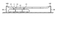
- FIG. 1 is a diagram showing an example of a mode of use of the balancer according to the first embodiment of the present invention.
- a current collector (pantograph) 21 on the roof of the train 20 is in contact with the overhead wire 10, and electric energy is supplied from the overhead wire 10.
- the overhead wire 10 includes a catenary wire 11, a trolley wire 12 that comes into contact with the pantograph 21 to supply power to the train 20, and a hanger 13.
- the trolley wire 12 is supported by a hanger 13 attached to the overhead wire 11.
- One end of the overhead wire 10 is fixed to the support column 30, and the other end is connected to the balancer 14.
- the balancer 14 is fixed to the support column 30.
- the balancer 14 adjusts the tensions of the overhead wire 11 and the trolley wire 12. For stable power supply to the train 20, it is important to stabilize the tension of the trolley wire 12. Therefore, it is required to stably control the tension of the overhead wire 10 by the balancer 14.
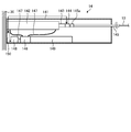
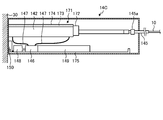
- FIG. 2 is a partial cross-sectional view showing the configuration of the balancer according to the first embodiment of the present invention.
- the balancer 14 includes a housing 141, a hydraulic cylinder 142, a piston rod 143, a tension sensor 144, a rod 145, a hydraulic pump 146, a hydraulic hose 147, a motor 148, a hydraulic oil tank 149, and drive control. It has a part 150 and the like.
- the actuator is composed of a hydraulic cylinder 142, a piston rod 143, a hydraulic pump 146, a hydraulic hose 147, and a motor 148.
- the housing 141 accommodates a hydraulic cylinder 142, a piston rod 143, a tension sensor 144, a rod 145, a hydraulic pump 146, a hydraulic hose 147, a motor 148, a hydraulic oil tank 149, and a drive control unit 150.
- the housing 141 extends a part of the rod 145 to the outside and accommodates the rod 145 so as to be able to move forward and backward in the longitudinal direction.
- the hydraulic cylinder 142 moves the piston rod 143 by the hydraulic oil supplied from the hydraulic pump 146 via the hydraulic hose 147.
- a positive pressure or a negative pressure is applied depending on the amount of hydraulic oil supplied, and the piston rod 143 moves according to the pressure.
- the tension sensor 144 is interposed between the piston rod 143 and the rod 145 and detects the tensile force of the rod 145. This tensile force corresponds to the tension of the overhead wire 10. Therefore, the tension sensor 144 detects the tension of the overhead wire 10 via the rod 145. The tension sensor 144 outputs the detected value to the drive control unit 150.
- the rod 145 is connected to the tension sensor 144, and the other end is connected to the overhead wire 10.
- the rod 145 is provided with a stopper 145a for adjusting the extension amount with respect to the housing 141.
- the stopper 145a is provided inside the housing 141, and the size of the rod 145 when viewed from the moving direction (longitudinal direction) is the opening of the hole (not shown) through which the rod 145 penetrates formed in the housing 141. Greater than size.
- the hydraulic pump 146 sends the hydraulic oil in the hydraulic oil tank 149 to the hydraulic hose 147 according to the drive of the motor 148, or sucks the hydraulic oil in the hydraulic cylinder 142 via the hydraulic hose 147.
- the motor 148 is configured by using, for example, a stepping motor, and is driven (rotated) according to a pulse signal from the control unit 154, and the amount of rotation thereof is controlled.
- the control unit 154 can grasp the position of the piston rod 143 in the hydraulic cylinder 142 by controlling the rotation amount of the motor 148.
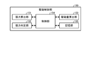
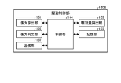
- FIG. 3 is a block diagram showing a configuration of a drive control unit in the balancer according to the first embodiment of the present invention.
- the drive control unit 150 includes a tension calculation unit 151, a tension determination unit 152, a drive amount calculation unit 153, a control unit 154, and a storage unit 155.
- the drive control unit 150 is realized by mounting a circuit on a substrate.
- the tension calculation unit 151 is communicably connected to the tension sensor 144.
- the tension calculation unit 151 calculates the tension applied to the rod 145 based on the detected value acquired from the tension sensor 144.
- the tension calculation unit 151 outputs the calculated tension to the control unit 154.
- the tension determination unit 152 determines whether or not the tension calculated by the tension calculation unit 151 is appropriate for the tension set in the overhead wire 10.
- the tension determination unit 152 determines whether or not the tension calculated by the tension calculation unit 151 satisfies the threshold value.
- An upper limit value and a lower limit value are set as the threshold value, and the range between the upper limit value and the lower limit value is an allowable range in which it is determined that the tension is appropriate.
- the tension determination unit 152 calculates the difference between the preset tension (reference tension) and the tension calculated by the tension calculation unit 151, compares this difference with the threshold value, and determines whether the tension is appropriate. It may be determined whether or not.
- the drive amount calculation unit 153 calculates the drive amount for moving the rod 145 when the tension does not satisfy the threshold value.
- the drive amount calculation unit 153 calculates the movement direction and the movement amount of the rod 145 based on the tension calculated by the tension calculation unit 151, and calculates the drive amount of the motor according to the movement direction and the movement amount.
- the drive amount is, for example, an output value.
- the drive amount calculation unit 153 increases the tension of the overhead wire 10 by pulling the piston rod 143 into the hydraulic cylinder 142.
- the drive amount calculation unit 153 reduces the tension of the overhead wire 10 by discharging the piston rod 143 from the hydraulic cylinder 142.
- the drive amount calculation unit 153 outputs the amount of movement in a predetermined direction as a positive (+) value, and outputs the amount of movement in the opposite direction as a negative ( ⁇ ) value.
- the control unit 154 controls the operation processing of each component of the balancer 14. For example, when the control unit 154 acquires the detected value from the tension sensor 144, the control unit 154 causes the tension adjustment process of the overhead wire 10 to be performed. The control unit 154 drives the motor 148 according to the drive amount calculated by the drive amount calculation unit 153.
- the control unit 154 needs to control the motor 148 at preset intervals to maintain the protrusion amount of the piston rod 143.
- the tension adjustment process may be performed before the time when the train 20 passes, without performing the tension adjustment while the train 20 does not pass.
- the "time when the train 20 passes” here refers to the time when the train 20 approaches the section of the trolley line where the tension is adjusted by the tension control of the overhead wire 10.
- the wave propagation speed which is the speed at which waves propagate on a trolley line or the like.
- the wave propagation velocity (m / s) is c
- the tension of the trolley wire is T
- the unit length mass (kg / m) of the trolley wire is ⁇
- the wave propagation velocity c is expressed by the following equation (1).
- NS. c ⁇ (T / ⁇ ) ⁇ ⁇ ⁇ (1)
- the tension may be higher than usual by acquiring the proximity information of the train in advance.
- the speed of trains is increasing year by year, but as described above, it is possible to cope with the speeding up by temporarily increasing the tension when the train approaches.
- the tension is increased by the braking amount of the actuator or the like. It is possible to increase the tension without changing the balancer.
- tension control may be performed in units of several seconds during the period before and after the train 20 passes.
- the trolley wire 12 sways due to the contact between the trolley wire 12 and the pantograph 21, and the tension of the trolley wire 12 changes due to the influence of this sway.
- By controlling the tension of the overhead wire 10 in units of several seconds it is possible to maintain an appropriate tension even when the tension changes due to the shaking of the trolley wire 12 when passing through the train 20.
- the storage unit 155 stores a program for the control unit 154 to execute various operations (for example, a program for driving a hydraulic pump), a threshold value (allowable range) related to tension determination processing, and the like.
- the storage unit 155 is configured by using a volatile memory or a non-volatile memory, or is configured by combining them.
- the storage unit 155 is configured by using a RAM (Random Access Memory), a ROM (Read Only Memory), or the like.
- the tension calculation unit 151, the tension determination unit 152, the drive amount calculation unit 153, and the control unit 154 each execute various specific functions such as a processor such as a CPU (Central Processing Unit) and an ASIC (Application Specific Integrated Circuit). It is configured using a processor such as an arithmetic circuit.
- a processor such as a CPU (Central Processing Unit) and an ASIC (Application Specific Integrated Circuit). It is configured using a processor such as an arithmetic circuit.
- the tension of the overhead wire 10 connected to the piston rod 143 is adjusted by controlling the piston rod 143 using the hydraulic pump 146.
- a hydraulic tension adjusting mechanism such as a hydraulic pump 146
- the tension change rate can be reduced without increasing the number of members (for example, coil springs), so that the size of the balancer can be suppressed.
- the rate of change in tension can be reduced.
- the tension of the overhead wire 10 can be adjusted.
- the tension of the overhead wire 10 is adjusted by a hydraulic actuator
- the overhead wire 10 is operated by an actuator different from the hydraulic type such as an actuator using a chain and an actuator using a ball screw.
- the tension of the can be adjusted.
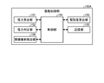
- FIG. 4 is a block diagram showing a configuration of a drive control unit in the balancer according to the first modification of the first embodiment of the present invention.
- the balancer 14 described above includes a drive control unit 150A instead of the drive control unit 150.
- the drive control unit 150A will be described.
- the same components as those in the first embodiment described above are designated by the same reference numerals.
- the drive control unit 150A includes a tension calculation unit 151, a tension determination unit 152, a drive amount calculation unit 153, a control unit 154, a storage unit 155, and an overhead wire wear detection unit 156.
- the overhead wire wear detection unit 156 detects the wear of the overhead wire 10 by detecting the elongation of the overhead wire 10 based on the relative position of the piston rod 143 in the hydraulic cylinder 142 and the tension detected at that time. For example, when the cross-sectional area of the trolley wire 12 changes due to wear or the like, the tension generated with respect to the tension of the rod 145 changes. Therefore, the position of the piston rod 143 in the hydraulic cylinder 142 changes when the tension is the same between the wear-free trolley wire 12 and the worn trolley wire 12.
- the elongation amount Y of the trolley wire 12 is expressed by the following equation, where L is the length of the trolley wire 12, x is the tension change amount, E is the Young's modulus of the trolley wire 12, and S is the cross-sectional area of the trolley wire 12. It can be expressed as 2).
- Y L ⁇ x / (E ⁇ S) ⁇ ⁇ ⁇ (2) If the tension of the trolley wire 12 having an unworn cross-sectional area of 120 mm 2 and an overhead wire length of 800 m and a Young's modulus of 10500 kgf / mm 2 is changed by 275 kgf, the trolley wire without wear is determined from the above equation (2).
- the elongation amount of the trolley wire 12 is 173 mm, and the elongation amount of the trolley wire 12 is 232 m when the cross-sectional area of the trolley wire 12 is 3/4 (90 mm 2). In this case, even if the tension is adjusted to be the same, there is a difference of about 60 mm in the elongation of the trolley wire 12. This difference can be detected as a change in the position of the piston rod 143 in the hydraulic cylinder 142.
- the overhead wire wear detection unit 156 detects the elongation of the overhead wire 10 from the change in the position of the piston rod 143. Here, the elongation of the overhead wire 10 as a whole due to the wear of the trolley wire 12 or the like is detected.
- the position of the piston rod 143 in the hydraulic cylinder 142 can be determined based on the amount of rotation of the motor 148.
- the overhead wire wear detection unit 156 detects the elongation of the overhead wire 10 based on the difference between the position of the piston rod 143 in the hydraulic cylinder 142 and the reference position when the tension is adjusted to the reference tension.
- the reference position is, for example, the position of the piston rod 143 in the hydraulic cylinder 142 when the tension of the overhead wire 10 without wear, which is stored in advance in the storage unit 155, is set as the set tension, or the wear immediately after the overhead wire 10 is installed. This is the position of the piston rod 143 in the hydraulic cylinder 142 when the tension of the overhead wire 10 is set as the set tension.
- the set tension referred to here is, for example, a tension set to be adjusted with respect to the overhead wire 10. For example, when the calculated difference is larger than the preset threshold value, the overhead wire wear detection unit 156 determines that the overhead wire 10 is stretched and worn.
- the threshold value is set based on, for example, the relationship between the strength of the overhead wire 10 having a cross-sectional area that decreases due to wear and the strength required for the overhead wire 10.
- the overhead wire wear detection unit 156 outputs the determination result to the control unit 154.
- control unit 154 When the control unit 154 acquires the determination result from the overhead wire wear detection unit 156, the control unit 154 stores the determination result in the storage unit 155 or transmits the determination result to the center that centrally manages the plurality of balancers 14. When transmitting the determination result to the center, the control unit 154 transmits information (for example, ID, etc.) for identifying itself (balancer 14) and the overhead wire 10 to be tension-adjusted together with the determination result.
- information for example, ID, etc.
- the tension of the overhead wire 10 connected to the piston rod 143 is adjusted by controlling the piston rod 143 using the hydraulic pump 146 as in the first embodiment.
- a hydraulic tension adjusting mechanism such as a hydraulic pump 146
- the tension change rate can be reduced without increasing the number of members (for example, coil springs), so that the increase in size of the balancer is suppressed.
- the rate of change in tension can be reduced.
- the overhead wire wear detection unit 156 detects the wear of the overhead wire 10 based on the position of the piston rod 143, so that the administrator can grasp the replacement time of the overhead wire 10. Is possible. As a result, the overhead wire 10 can be replaced at an appropriate timing.
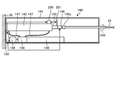
- FIG. 5 is a partial cross-sectional view showing the configuration of the balancer according to the second modification of the first embodiment of the present invention.
- the balancer 14A according to the second modification further includes a laser distance sensor 200 and a reflector 201 with respect to the balancer 14 described above.
- the configurations of the laser distance sensor 200 and the reflector 201 will be described.
- the same components as those in the first embodiment described above are designated by the same reference numerals.
- the laser distance sensor 200 is provided on the outer surface of the hydraulic cylinder 142.
- the reflector 201 is erected on the piston rod 143 at a position where the laser emitted by the laser distance sensor 200 can be reflected.
- the laser distance sensor 200 emits a laser toward the reflector 201 and receives the laser reflected by the reflector 201.
- the laser distance sensor 200 outputs, for example, information on the time from when the laser is emitted by itself to when the laser is reflected by the reflector 201 and received, or information on the phase difference between the emitted light and the return light to the control unit 154. ..
- the control unit 154 measures the distance between the laser distance sensor 200 and the reflector 201 based on the information acquired from the laser distance sensor 200.
- the control unit 154 determines the position of the piston rod 143 in the hydraulic cylinder 142 based on the measured distance, the position of the laser distance sensor 200 in the hydraulic cylinder 142, and the position of the reflector 201 in the piston rod 143.
- Other processes related to tension control are the same as those in the first embodiment.
- the tension of the overhead wire 10 connected to the piston rod 143 is adjusted by controlling the piston rod 143 using the hydraulic pump 146 as in the first embodiment.
- the tension change rate can be reduced without increasing the number of members (for example, coil springs), so that the increase in size of the balancer is suppressed.
- the rate of change in tension can be reduced.
- the position of the piston rod 143 is detected based on the laser reflected by the reflector 201, so that the detection result is based on the position of the reflector 201 according to the actual movement position of the piston rod 143. It becomes. Therefore, in the position detection using the laser distance sensor 200 and the reflector 201, the position of the piston rod 143 can be detected more accurately.
- the method of detecting the position of the piston rod 143 in the hydraulic cylinder 142 is not limited to the motor control and the distance measurement by the laser described above, and a known method can be used.
- FIGS. 6 and 7 are partial cross-sectional views showing the configuration of the balancer according to the third modification of the first embodiment of the present invention.
- the balancer 14B according to the third modification further includes a rust preventive mechanism 161 with respect to the balancer 14 described above.
- the rust preventive mechanism 161 will be described.
- the same components as those in the first embodiment described above are designated by the same reference numerals.
- the rust preventive mechanism 161 has a sealing case 162, an expansion / contraction member 163, and an oil pan 164.
- the sealed case 162 has a cylindrical shape with one end connected to the hydraulic cylinder 142, and the piston rod 143 is inserted through the sealed case 162.
- the telescopic member 163 is provided in the sealed case 162, one end of which is fixed to the inner wall of the sealed case 162, and the other end of which is fixed to the tension sensor 144.
- the telescopic member 163 forms a sealing space for sealing the end portion of the piston rod 143 on the tension sensor 144 side by the telescopic member 163 and the inner wall of the sealing case 162.
- the sealed space is filled with an inert gas. Examples of the inert gas include nitrogen and rare gas elements.
- the oil pan 164 receives the hydraulic oil leaking from the hydraulic cylinder 142 and the like.
- the telescopic member 163 expands and contracts in conjunction with the movement of the piston rod 143. For example, when the piston rod 143 is pulled into the hydraulic cylinder 142 (see FIG. 7) from the state where the tension sensor 144 is located outside the sealed case 162 (see FIG. 6), the telescopic member 163 moves the piston rod 143. It contracts in tandem. At this time, since the sealed state between the expansion / contraction member 163 and the sealing case 162 is maintained, the piston rod 143 is maintained in the sealed state in the atmosphere of the inert gas.
- the tension of the overhead wire 10 connected to the piston rod 143 is adjusted by controlling the piston rod 143 using the hydraulic pump 146 as in the first embodiment.
- a hydraulic tension adjusting mechanism such as a hydraulic pump 146
- the tension change rate can be reduced without increasing the number of members (for example, coil springs), so that the increase in size of the balancer is suppressed.
- the rate of change in tension can be reduced.
- the rust preventive mechanism 161 keeps the piston rod 143 in a sealed state in an inert gas atmosphere regardless of the movement of the piston rod 143. The generation of rust can be suppressed.
- FIGS. 8 and 9 are partial cross-sectional views showing the configuration of the balancer according to the fourth modification of the first embodiment of the present invention.
- the balancer 14C according to the fourth modification further includes a rust preventive mechanism 171 with respect to the balancer 14 described above.
- the rust preventive mechanism 171 will be described.
- the same components as those in the first embodiment described above are designated by the same reference numerals.
- the rust preventive mechanism 171 includes a wiper 172, a support member 173, a wiper hydraulic cylinder 174, and an oil pan 175.
- the wiper 172 is supplied with rust preventive oil via the wiper hydraulic cylinder 174. Therefore, the wiper 172 is in a state of containing rust preventive oil.
- the rust preventive oil may be the hydraulic oil described above, or may be an oil selected according to the material of the piston rod 143.
- the hydraulic oil tank 149 may be used in common, or a tank different from the hydraulic oil tank 149 may be provided. Further, when supplying rust preventive oil different from the hydraulic oil to the wiper 172, a tank different from the hydraulic oil tank 149 is provided.
- the support member 173 supports the wiper 172 at one end, and the other end is housed in the wiper hydraulic cylinder 174.
- the support member 173 is provided so as to be able to move forward and backward with respect to the wiper hydraulic cylinder 174 under the control of the control unit 154.
- the oil pan 175 receives the hydraulic oil leaking from the wiper 172 and the like.
- the control unit 154 reciprocates the wiper 172 between the end of the piston rod 143 on the hydraulic cylinder 142 side and the tension sensor 144 by moving the support member 173. By the reciprocating movement of the wiper 172, the surface of the piston rod 143 is coated with working or rust preventive oil.
- the control unit 154 may reciprocate the wiper 172 at preset intervals, or may reciprocate the wiper 172 according to the instruction of the administrator.
- the tension of the overhead wire 10 connected to the piston rod 143 is adjusted by controlling the piston rod 143 using the hydraulic pump 146 as in the first embodiment.
- the tension change rate can be reduced without increasing the number of members (for example, coil springs), so that the increase in size of the balancer is suppressed.
- the rate of change in tension can be reduced.
- the rust preventive mechanism 171 keeps the piston rod 143 covered with the hydraulic oil or the rust preventive oil, so that the occurrence of rust on the piston rod 143 can be suppressed. can.
- regular rust prevention treatment is effective. Since the piston rod 143 may move from the minimum movement position to the maximum movement position of the stroke over a year, for example, it is exposed to the outside air for a long period of time, and it is preferable to carry out rust prevention treatment on a regular basis.
- the rack and pinion may be driven by a motor to move the wiper 172.
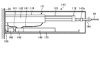
- FIG. 10 is a diagram showing an example of a mode of use of the balancer according to the second embodiment of the present invention.
- the first embodiment described above an example in which one end of the overhead wire 10 is fixed to the support column 30 and the balancer 14 is provided at the other end has been described, but in the second embodiment, balancers are provided at both ends of the overhead wire 10.
- the same components as those in the first embodiment described above are designated by the same reference numerals.
- one end of the overhead wire 10 is connected to the support column 30 via the balancer 14D, and the other end is connected to the support column 30 via the balancer 14E.
- the tension of the overhead wire 10 is adjusted by two balancers 14D and 14E.
- the balancers 14D and 14E provided on the same overhead wire 10 for tension adjustment function as a pair of balancers.
- the balancers 14D and 14E each have the same configuration as the balancer 14 described above. That is, the balancers 14D and 14E include the housing 141, the hydraulic cylinder 142, the piston rod 143, the tension sensor 144, the rod 145, the hydraulic pump 146, the hydraulic hose 147, the motor 148, and the hydraulic oil tank 149. And a drive control unit 150, respectively.
- Each control unit 154 of the balancers 14D and 14E controls the piston rod 143 based on the calculated tension.
- the control timings of the piston rods 143 of the balancer 14D and the balancer 14E may be individual or may be synchronized. When the piston rods 143 are controlled at the same time, they may be controlled at different times.
- the drive control unit 150 of each balancer may change the set tension based on the position of the piston rod 143 and the detection result by the tension sensor 144.
- the drive control unit 150 changes the set tension by performing control imitating Hooke's law in which the elongation of the spring is proportional to the load below the elastic limit.
- the stroke amount of the balancer is increased to control the tension to an appropriate level.
- the balancer does not have a spring member (for example, a coil spring)
- the stroke amount of the piston rod 143 in both balancers is controlled to the same extent even if the tension is controlled to an appropriate value, for example.
- the stroke amount of one balancer may increase.
- the balancers mutually.
- the tension between the two balancers is adjusted so as to be balanced, and the position of the piston rod 143 in the paired balancers (here, balancers 14D and 14E) in the hydraulic cylinder 142 (in this case, the balancers 14D and 14E) without communicating and controlling the information of The stroke amount) can be controlled to a relatively similar level.
- the tension of the overhead wire 10 connected to the piston rod 143 is adjusted by controlling the piston rod 143 using the hydraulic pump 146 as in the first embodiment.
- a hydraulic tension adjusting mechanism such as a hydraulic pump 146
- the tension change rate can be reduced without increasing the number of members (for example, coil springs), so that the size of the balancer can be suppressed.
- the rate of change in tension can be reduced.
- balancers are provided at both ends of the overhead wire 10 to adjust the tension at both ends of the overhead wire 10, so that the tension adjustment width (total movement amount by each piston rod 143). ) Can be taken large.
- the balancers 14A to 14C according to the first and second modifications of the first embodiment may be used.
- FIG. 11 is a block diagram showing a configuration of a drive control unit in the balancer according to the first modification of the second embodiment of the present invention.
- the balancers 14D and 14E described above include a drive control unit 150B instead of the drive control unit 150.
- the drive control unit 150B will be described.
- the same components as those in the first and second embodiments described above are designated by the same reference numerals.
- the drive control unit 150B includes a tension calculation unit 151, a tension determination unit 152, a drive amount calculation unit 153, a control unit 154, a storage unit 155, and a communication unit 157.
- the communication unit 157 transmits and receives a control signal to and from the other balancer in the pair.
- the communication unit 157 of the balancer 14D transmits and receives a control signal to and from the communication unit 157 of the paired balancer 14E.
- the communication unit 157 may transmit and receive signals using the overhead wire 10 as a transmission path, or may transmit and receive signals by wireless communication.
- the balancers 14D and 14E control the movement of the piston rod 143 in cooperation with each other.
- one is set as the main balancer and the other is set as the secondary balancer, and the balancers paired with the main balancer are collectively controlled.
- the control unit 154 of the balancer 14D causes the tension calculation unit 151 and the tension determination unit 152 of the balancer 14E to perform the tension determination process.
- the control unit 154 does not perform the tension adjusting process when it is determined that the tension is appropriate.
- the control unit 154 of the balancer 14E causes the tension calculation unit 151 and the tension determination unit 152 of the balancer 14E to perform the tension determination process, and the tension of the balancer 14E and the tension of the balancer 14E are determined.
- the determination result of the tension and the position information of the piston rod 143 are acquired.
- the drive amount calculation unit 153 of the balancer 14D sets the movement direction and the movement amount of the piston rod 143 of each balancer based on the tension of each balancer, the determination result, and the position of the piston rod 143.
- the control unit 154 of the balancer 14D controls the piston rod 143 of the balancer 14D, and transmits control information of the piston rod 143 to the balancer 14E via the communication unit 157. At this time, the movement of the piston rod 143 between the balancer 14D and the balancer 14E may be performed individually or synchronously.
- the tension of the overhead wire 10 connected to the piston rod 143 is adjusted by controlling the piston rod 143 using the hydraulic pump 146 as in the second embodiment.
- a hydraulic tension adjusting mechanism such as a hydraulic pump 146
- the tension change rate can be reduced without increasing the number of members (for example, coil springs), so that the increase in size of the balancer is suppressed.
- the rate of change in tension can be reduced.
- the balancers communicate with each other via the communication unit 157, and the piston rod 143 is controlled in an integrated manner according to the tension, so that the load applied to one balancer is reduced. be able to.
- the drive control unit of the balancer 14E includes a tension calculation unit 151, a tension determination unit 152, a control unit 154, a storage unit 155, and a communication unit 157.
- the tension determination unit 152 of the balancer 14D determines the suitability of the tension of the balancer 14E based on the tension acquired from the balancer 14E, the balancer 14E may not have the tension determination unit 152.
- the drive control unit of the balancer 14E includes a tension calculation unit 151, a control unit 154, a storage unit 155, and a communication unit 157.
- FIG. 12 is a block diagram showing a configuration of a drive control unit in the balancer according to the second modification of the second embodiment of the present invention.
- the balancers 14D and 14E described above include a drive control unit 150C instead of the drive control unit 150.
- the drive control unit 150C will be described.
- the same components as those in the first and second embodiments described above are designated by the same reference numerals.
- the drive control unit 150C includes a tension calculation unit 151, a tension determination unit 152, a drive amount calculation unit 153, a control unit 154, a storage unit 155, an overhead wire wear detection unit 156, a communication unit 157, and a GPS (Global). It has a Positioning System) unit 158.
- at least the balancer 14D is provided with a generator that generates vibration for wear detection. An actuator may be used as the vibration generator.
- the GPS unit 158 is configured by using a receiver that receives radio waves from GPS satellites.
- the GPS unit 158 acquires time information based on the received radio wave, and outputs the acquired time information to the control unit 154.
- GNSS Global Navigation Satellite System
- the GPS unit 158 acquires time information at a preset interval or a preset time.
- the control unit 154 resets the time based on the acquired time information.
- the control unit 154 of each balancer can synchronize the time between balancers by setting the time based on GPS.
- the wear of the trolley wire 12 is detected by detecting the signal transmission speed between the balancers 14D and 14E.
- the control unit 154 of the balancer 14D when the balancer 14D is the main and the balancer 14E is the sub, the control unit 154 of the balancer 14D generates vibration for detecting the wear of the overhead wire via the overhead wire 10 (the overhead wire 11 or the trolley wire 12). It is sent to the balancer 14E to start the overhead wire wear detection process.
- the overhead wire wear detection unit 156 of the balancer 14D generates vibration for wear detection in the balancer 14E. It suffices if the balancer 14E can recognize that the vibration generated at this time is the vibration for detecting the wear of the overhead wire 10.
- the balancer 14E receives the vibration for detecting wear, it transmits a signal including the time when the vibration is received to the balancer 14D.
- the overhead wire wear detection unit 156 of the balancer 14D acquires the vibration reception time from the balancer 14E, it calculates the difference from the time when the vibration is generated by itself. This difference corresponds to the transmission time required to transmit the vibration flowing through the overhead wire 10 between the balancer 14D and the balancer 14E.
- the overhead wire wear detection unit 156 of the balancer 14D compares the calculated transmission time with the threshold value to detect the wear of the overhead wire 10.
- the threshold value here is a value corresponding to the transmission time of the overhead wire 10 (trolley wire 12) without wear, and is, for example, a preset value or a transmission time calculated immediately after the overhead wire 10 is replaced. ..
- the overhead wire wear detection unit 156 of the balancer 14D determines that the overhead wire 10 is worn when the calculated transmission time is smaller than the threshold value.
- the overhead wire wear detection unit 156 of the balancer 14D outputs the determination result to the control unit 154.
- control unit 154 When the control unit 154 acquires the judgment result from the overhead wire wear detection unit 156, the control unit 154 stores the judgment result in the storage unit 155 or transmits the judgment result to the center that centrally manages a plurality of balancers. When transmitting the determination result to the center, the control unit 154 transmits information (for example, ID, etc.) for identifying its own balancer 14D and the overhead wire 10 to be tension-adjusted together with the determination result.
- information for example, ID, etc.
- the tension of the overhead wire 10 connected to the piston rod 143 is adjusted by controlling the piston rod 143 using the hydraulic pump 146 as in the second embodiment.
- the tension change rate can be reduced without increasing the number of members (for example, coil springs), so that the increase in size of the balancer is suppressed.
- the rate of change in tension can be reduced.
- the overhead wire wear detection unit 156 detects the wear of the overhead wire 10 based on the transmission speed of the vibration between the balancers 14D and 14E. Etc. can be grasped.
- the drive control unit of the balancer 14E includes a tension calculation unit 151, a tension determination unit 152, a drive amount calculation unit 153, a control unit 154, a storage unit 155, a communication unit 157, and a GPS unit 158.
- the GPS unit 158 may not be provided.
- the signal for detecting the wear is not limited to the vibration, for example, a sound wave.
- the propagation velocity may be measured to detect the elongation of the overhead wire 10.
- one balancer is provided with a generator that generates sound, and the other balancer is provided with a receiver that receives the sound generated by the generator.
- the control device for controlling the two balancers.
- the control device may be configured to control the two balancers in an integrated manner.
- the drive control unit of each balancer has at least a control unit 154, a storage unit 155, and a communication unit 157.
- the control device acquires the detection value of the tension sensor from each balancer, determines the suitability of the tension, calculates the drive amount of the piston rod 143, and transmits the drive amount to each balancer. In this way, the control device controls each balancer by executing some of the functions of the balancers described above.
- the present invention may include various embodiments not described here, and various design changes and the like may be made within a range that does not deviate from the technical idea specified by the claims. Is possible.
- the above-described embodiment an example of adjusting the tension of the train line has been described, but in addition, the above-mentioned balancer can be adopted for the object for adjusting the tension of the wire rod.
- the balancer and the balancer system according to the present invention are suitable for reducing the tension change rate while suppressing the increase in size.
- Overhead wire 11 Overhead wire 12 Trolley wire 13 Hanger 14, 14A-14E Balancer 20 Train 21 Pantograph 30 Strut 141 Housing 142 Hydraulic cylinder 143 Piston rod 144 Tension sensor 145 Rod 146 Hydraulic pump 147 Hydraulic hose 148 Hydraulic hose 148 150A-150C Drive control unit 151 Tension calculation unit 152 Tension determination unit 153 Drive amount calculation unit 154 Control unit 155 Storage unit 156 Overhead wire wear detection unit 157 Communication unit 158 GPS unit 161 and 171 Anti-corrosion mechanism 200 Laser distance sensor 201 Reflector
Landscapes
- Engineering & Computer Science (AREA)
- Mechanical Engineering (AREA)
- Physics & Mathematics (AREA)
- Fluid Mechanics (AREA)
- General Engineering & Computer Science (AREA)
- Suspension Of Electric Lines Or Cables (AREA)
Abstract
Cet équilibreur comprend : un actionneur pour ajuster la tension d'un fil; un capteur de tension disposé entre le fil et l'actionneur pour détecter la tension du fil; et une unité de commande d'entraînement pour commander l'actionneur sur la base de la tension du fil détectée par le capteur de tension.
Priority Applications (2)
| Application Number | Priority Date | Filing Date | Title |
|---|---|---|---|
| EP21781597.6A EP4131690A4 (fr) | 2020-03-31 | 2021-03-10 | Dispositif d'équilibrage et d'équilibreur |
| KR1020227033550A KR20220146598A (ko) | 2020-03-31 | 2021-03-10 | 밸런서 및 밸런서 시스템 |
Applications Claiming Priority (2)
| Application Number | Priority Date | Filing Date | Title |
|---|---|---|---|
| JP2020063175A JP7391750B2 (ja) | 2020-03-31 | 2020-03-31 | バランサおよびバランサシステム |
| JP2020-063175 | 2020-03-31 |
Publications (1)
| Publication Number | Publication Date |
|---|---|
| WO2021199999A1 true WO2021199999A1 (fr) | 2021-10-07 |
Family
ID=77928691
Family Applications (1)
| Application Number | Title | Priority Date | Filing Date |
|---|---|---|---|
| PCT/JP2021/009666 Ceased WO2021199999A1 (fr) | 2020-03-31 | 2021-03-10 | Dispositif d'équilibrage et d'équilibreur |
Country Status (4)
| Country | Link |
|---|---|
| EP (1) | EP4131690A4 (fr) |
| JP (3) | JP7391750B2 (fr) |
| KR (1) | KR20220146598A (fr) |
| WO (1) | WO2021199999A1 (fr) |
Families Citing this family (2)
| Publication number | Priority date | Publication date | Assignee | Title |
|---|---|---|---|---|
| JP7391750B2 (ja) * | 2020-03-31 | 2023-12-05 | 日本発條株式会社 | バランサおよびバランサシステム |
| JP2024113959A (ja) * | 2023-02-10 | 2024-08-23 | 日本発條株式会社 | テンションバランサ |
Citations (3)
| Publication number | Priority date | Publication date | Assignee | Title |
|---|---|---|---|---|
| JPH07156699A (ja) * | 1993-12-07 | 1995-06-20 | East Japan Railway Co | 2重シリンダ式テンションバランサ |
| JPH09328025A (ja) * | 1996-06-11 | 1997-12-22 | Nagano Keiki Seisakusho Ltd | 架線の張力調節装置 |
| JP3666971B2 (ja) | 1996-01-31 | 2005-06-29 | 三和テッキ株式会社 | ばね式テンションバランサ |
Family Cites Families (16)
| Publication number | Priority date | Publication date | Assignee | Title |
|---|---|---|---|---|
| JPS5034685U (fr) * | 1973-07-27 | 1975-04-14 | ||
| JPS6069844U (ja) * | 1983-10-20 | 1985-05-17 | トキコ株式会社 | 減衰力調整式油圧緩衝器 |
| JPH08216739A (ja) * | 1994-12-14 | 1996-08-27 | Shinyoushiya:Kk | 架線長異常検出装置およびシステム |
| JPH08278215A (ja) * | 1995-03-31 | 1996-10-22 | Yaskawa Electric Corp | 架空電線の張力自動監視装置 |
| JPH08334421A (ja) * | 1995-06-06 | 1996-12-17 | Central Japan Railway Co | トロリ線の張力測定方法 |
| JP2000065118A (ja) * | 1998-08-25 | 2000-03-03 | Toyo Constr Co Ltd | 防錆型ダンパ及び船舶衝撃力吸収装置 |
| ITUD20010023A1 (it) * | 2001-02-09 | 2002-08-09 | Tesmec Spa | Procedimento di regolazione della tensione per macchine di tesatura e relativo apparato |
| JP2003074514A (ja) * | 2001-08-31 | 2003-03-12 | Hitachi Constr Mach Co Ltd | シリンダ装置 |
| JP3864775B2 (ja) * | 2001-12-13 | 2007-01-10 | 日立電線株式会社 | トロリ線の異常検出方法 |
| JP2008223797A (ja) * | 2007-03-08 | 2008-09-25 | Nhk Spring Co Ltd | ガススプリング |
| JP5203734B2 (ja) * | 2008-02-01 | 2013-06-05 | 東海旅客鉄道株式会社 | 架空線用テンション装置 |
| JP2016165956A (ja) * | 2015-03-10 | 2016-09-15 | 株式会社日立製作所 | 磨耗判定システム |
| KR101775986B1 (ko) * | 2017-02-01 | 2017-09-07 | 김성찬 | 현수선 구조설비용 장력조절장치 |
| JP6869073B2 (ja) * | 2017-03-29 | 2021-05-12 | 三和テッキ株式会社 | 架空線の張力変化低減装置 |
| CN108728205B (zh) * | 2018-07-27 | 2021-05-11 | 南京科润工业介质股份有限公司 | 一种气相防锈油 |
| JP7391750B2 (ja) * | 2020-03-31 | 2023-12-05 | 日本発條株式会社 | バランサおよびバランサシステム |
-
2020
- 2020-03-31 JP JP2020063175A patent/JP7391750B2/ja active Active
-
2021
- 2021-03-10 WO PCT/JP2021/009666 patent/WO2021199999A1/fr not_active Ceased
- 2021-03-10 EP EP21781597.6A patent/EP4131690A4/fr not_active Withdrawn
- 2021-03-10 KR KR1020227033550A patent/KR20220146598A/ko not_active Ceased
-
2023
- 2023-11-22 JP JP2023198395A patent/JP2024009213A/ja active Pending
- 2023-11-22 JP JP2023198394A patent/JP2024009212A/ja active Pending
Patent Citations (3)
| Publication number | Priority date | Publication date | Assignee | Title |
|---|---|---|---|---|
| JPH07156699A (ja) * | 1993-12-07 | 1995-06-20 | East Japan Railway Co | 2重シリンダ式テンションバランサ |
| JP3666971B2 (ja) | 1996-01-31 | 2005-06-29 | 三和テッキ株式会社 | ばね式テンションバランサ |
| JPH09328025A (ja) * | 1996-06-11 | 1997-12-22 | Nagano Keiki Seisakusho Ltd | 架線の張力調節装置 |
Non-Patent Citations (1)
| Title |
|---|
| See also references of EP4131690A4 |
Also Published As
| Publication number | Publication date |
|---|---|
| KR20220146598A (ko) | 2022-11-01 |
| JP2024009212A (ja) | 2024-01-19 |
| JP7391750B2 (ja) | 2023-12-05 |
| JP2021160501A (ja) | 2021-10-11 |
| EP4131690A4 (fr) | 2024-03-06 |
| JP2024009213A (ja) | 2024-01-19 |
| EP4131690A1 (fr) | 2023-02-08 |
Similar Documents
| Publication | Publication Date | Title |
|---|---|---|
| JP2024009212A (ja) | バランサおよびバランサシステム | |
| US11602970B2 (en) | Electric suspension device | |
| NO20220516A1 (no) | Et dataprogramprodukt og et kontrollsystem for å kompensere for bevegelsene til et skip som flyter på vann | |
| KR101450734B1 (ko) | 특고압 송배전선의 안정된 고정을 유지하는 완금 | |
| JPH0710642B2 (ja) | ドップラー流体速度センサを備えるショック・アブソーバ | |
| JPH063239B2 (ja) | 調整可能な振動ダンパ | |
| EP0502184A4 (en) | Shock absorber with sonar position sensor | |
| US20080134787A1 (en) | Vibration reducing device and vibration reducing method | |
| JPH04221217A (ja) | 油圧アクチュエータと相対運動の測定方法 | |
| US20200399069A1 (en) | Damping station for an overhead conveyor system, and method for damping vibrations of cargo of an overhead conveyor system | |
| US12006646B2 (en) | Fender | |
| JP2014088156A (ja) | 前照灯用光軸制御装置 | |
| KR20100027368A (ko) | Mr댐퍼를 이용한 지능형 궤도레일방진시스템 | |
| KR101055069B1 (ko) | 추진축 센터베어링 높이 조절장치 | |
| JP2010254062A (ja) | 車両制御装置 | |
| JP2010106617A (ja) | 昇降移動物を備えた塔状構造物の制振方法及び装置 | |
| US20140087902A1 (en) | Tensioning device for a traction-device drive | |
| KR101523217B1 (ko) | 탑 브레이싱 | |
| RU2005120743A (ru) | Устройство приводного соединения в лифтовых установках, снабженных средствами привода и средствами подвески, независимыми друг от друга | |
| KR100456769B1 (ko) | 차량의 능동형 진동 제어장치 | |
| US20250346084A1 (en) | Suspension control apparatus and suspension control method | |
| JP4429957B2 (ja) | 車体制振装置 | |
| JP2010241356A (ja) | 鉄道用車両の制振装置 | |
| NZ767909B2 (en) | Fender | |
| KR20080052985A (ko) | 열차 집전장치의 추종특성 액티브 제어 시스템 및 그 방법 |
Legal Events
| Date | Code | Title | Description |
|---|---|---|---|
| 121 | Ep: the epo has been informed by wipo that ep was designated in this application |
Ref document number: 21781597 Country of ref document: EP Kind code of ref document: A1 |
|
| ENP | Entry into the national phase |
Ref document number: 20227033550 Country of ref document: KR Kind code of ref document: A |
|
| NENP | Non-entry into the national phase |
Ref country code: DE |
|
| ENP | Entry into the national phase |
Ref document number: 2021781597 Country of ref document: EP Effective date: 20221031 |