WO2021205920A1 - Procédé pour la production d'un film de revêtement - Google Patents
Procédé pour la production d'un film de revêtement Download PDFInfo
- Publication number
- WO2021205920A1 WO2021205920A1 PCT/JP2021/013082 JP2021013082W WO2021205920A1 WO 2021205920 A1 WO2021205920 A1 WO 2021205920A1 JP 2021013082 W JP2021013082 W JP 2021013082W WO 2021205920 A1 WO2021205920 A1 WO 2021205920A1
- Authority
- WO
- WIPO (PCT)
- Prior art keywords
- film
- coating liquid
- coating
- surface temperature
- film surface
- Prior art date
- Legal status (The legal status is an assumption and is not a legal conclusion. Google has not performed a legal analysis and makes no representation as to the accuracy of the status listed.)
- Ceased
Links
Images


Classifications
-
- B—PERFORMING OPERATIONS; TRANSPORTING
- B05—SPRAYING OR ATOMISING IN GENERAL; APPLYING FLUENT MATERIALS TO SURFACES, IN GENERAL
- B05D—PROCESSES FOR APPLYING FLUENT MATERIALS TO SURFACES, IN GENERAL
- B05D3/00—Pretreatment of surfaces to which liquids or other fluent materials are to be applied; After-treatment of applied coatings, e.g. intermediate treating of an applied coating preparatory to subsequent applications of liquids or other fluent materials
- B05D3/02—Pretreatment of surfaces to which liquids or other fluent materials are to be applied; After-treatment of applied coatings, e.g. intermediate treating of an applied coating preparatory to subsequent applications of liquids or other fluent materials by baking
-
- B—PERFORMING OPERATIONS; TRANSPORTING
- B05—SPRAYING OR ATOMISING IN GENERAL; APPLYING FLUENT MATERIALS TO SURFACES, IN GENERAL
- B05D—PROCESSES FOR APPLYING FLUENT MATERIALS TO SURFACES, IN GENERAL
- B05D3/00—Pretreatment of surfaces to which liquids or other fluent materials are to be applied; After-treatment of applied coatings, e.g. intermediate treating of an applied coating preparatory to subsequent applications of liquids or other fluent materials
-
- B—PERFORMING OPERATIONS; TRANSPORTING
- B05—SPRAYING OR ATOMISING IN GENERAL; APPLYING FLUENT MATERIALS TO SURFACES, IN GENERAL
- B05D—PROCESSES FOR APPLYING FLUENT MATERIALS TO SURFACES, IN GENERAL
- B05D7/00—Processes, other than flocking, specially adapted for applying liquids or other fluent materials to particular surfaces or for applying particular liquids or other fluent materials
-
- B—PERFORMING OPERATIONS; TRANSPORTING
- B05—SPRAYING OR ATOMISING IN GENERAL; APPLYING FLUENT MATERIALS TO SURFACES, IN GENERAL
- B05D—PROCESSES FOR APPLYING FLUENT MATERIALS TO SURFACES, IN GENERAL
- B05D7/00—Processes, other than flocking, specially adapted for applying liquids or other fluent materials to particular surfaces or for applying particular liquids or other fluent materials
- B05D7/02—Processes, other than flocking, specially adapted for applying liquids or other fluent materials to particular surfaces or for applying particular liquids or other fluent materials to macromolecular substances, e.g. rubber
- B05D7/04—Processes, other than flocking, specially adapted for applying liquids or other fluent materials to particular surfaces or for applying particular liquids or other fluent materials to macromolecular substances, e.g. rubber to surfaces of films or sheets
-
- B—PERFORMING OPERATIONS; TRANSPORTING
- B05—SPRAYING OR ATOMISING IN GENERAL; APPLYING FLUENT MATERIALS TO SURFACES, IN GENERAL
- B05D—PROCESSES FOR APPLYING FLUENT MATERIALS TO SURFACES, IN GENERAL
- B05D2252/00—Sheets
- B05D2252/02—Sheets of indefinite length
-
- Y—GENERAL TAGGING OF NEW TECHNOLOGICAL DEVELOPMENTS; GENERAL TAGGING OF CROSS-SECTIONAL TECHNOLOGIES SPANNING OVER SEVERAL SECTIONS OF THE IPC; TECHNICAL SUBJECTS COVERED BY FORMER USPC CROSS-REFERENCE ART COLLECTIONS [XRACs] AND DIGESTS
- Y02—TECHNOLOGIES OR APPLICATIONS FOR MITIGATION OR ADAPTATION AGAINST CLIMATE CHANGE
- Y02E—REDUCTION OF GREENHOUSE GAS [GHG] EMISSIONS, RELATED TO ENERGY GENERATION, TRANSMISSION OR DISTRIBUTION
- Y02E60/00—Enabling technologies; Technologies with a potential or indirect contribution to GHG emissions mitigation
- Y02E60/10—Energy storage using batteries
Definitions
- This disclosure relates to a method for manufacturing a coating film.
- a method of producing a target coating film on a support by a continuous process of a roll-to-roll method is known.
- a method for producing a coating film for example, there is a method of applying a coating liquid for obtaining a target coating film on a support and drying the obtained coating liquid film.
- Patent Document 1 includes a drying step of applying an ink absorbing layer coating solution containing inorganic fine particles and a water-soluble resin to a continuously running web and then drying the ink absorbing layer.
- a method for producing an inkjet recording sheet is disclosed in which the drying rate distribution of the ink absorbing layer in the web width direction is within 20% in the drying step.
- Patent Document 2 inorganic fine particles are dispersed in the presence of a water-soluble polyvalent metal compound to obtain a dispersion (1), and separately, inorganic fine particles are dispersed in the presence of an organic cationic polymer to obtain a dispersion (2). ), The obtained dispersions (1) and (2) are mixed, coated on a support, and dried.
- Patent Document 3 describes a step of applying a negative electrode paste containing a negative electrode active material, a thickener and a binder to the surface of a negative electrode current collector, and a step of applying the negative electrode paste to the surface of the negative electrode current collector.
- a method for manufacturing a negative electrode including a drying step of drying the formed negative electrode paste layer so as to satisfy Equation 1: (surface temperature of the negative electrode paste layer)-(temperature of the negative electrode current collector) ⁇ 1 ° C. is disclosed. There is.
- it is a method of manufacturing a coating film on a support that is continuously conveyed, such as a continuous process in a roll-to-roll method, in which a water-based coating liquid is applied onto a support having high thermal conductivity.
- a coating film in which the step of forming the coating liquid film and the step of drying the formed coating liquid film are performed, cracks occur at the widthwise end of the obtained coating film.
- the problem to be solved by one embodiment of the present disclosure has been made in view of the above circumstances, and is a method of manufacturing a coating film on a support that is continuously conveyed (for example, by a roll-to-roll method).
- Means for solving the above problems include the following embodiments. ⁇ 1> A step A in which a long support having a thermal conductivity of 200 W / (m ⁇ K) or more is continuously transported and a water-based coating liquid is applied onto the continuously transported support, and the continuous transport is performed. Including step B of drying the coating liquid film obtained in step A on the support. Step B includes a constant drying step of the coating liquid film satisfying the following conditions (1) and (2). Manufacturing method of coating film. Condition (1): The film surface temperature at a position 5 mm from the widthwise edge of the coating liquid film at T0% when the constant drying is started is set to A (T0%) , and the center in the width direction of the coating liquid film.
- the film surface temperature of the part is B (T0%)
- the film surface temperature at a position 5 mm from the widthwise edge of the coating liquid film at T90% after 90% of the constant drying time is A (T90). %)
- the film surface temperature B (T90%) at the center of the coating liquid film in the width direction ⁇ T [° C.] obtained from the following formula (A) is ⁇ 10 ° C. ⁇ T ⁇ 0 ° C. ..
- Formula (A) ⁇ T [° C.] (A (T0%) -B (T0%) )-(A (T90%) -B (90%) )
- Condition (2) The average value of the film surface temperature A (T0%) , the film surface temperature B (T0%) , the film surface temperature A (T90%) , and the film surface temperature B (T90%) is 35 ° C. or higher. ..
- ⁇ 2> When the thickness at a position 5 mm from the widthwise edge of the coating liquid film is At and the thickness at the center of the coating liquid film in the width direction is Bt, 0.9 ⁇ At / Bt ⁇ 1.1.
- the method for producing a coating film according to ⁇ 1> which satisfies the above relationship.
- ⁇ 3> The method for producing a coating film according to ⁇ 1> or ⁇ 2>, wherein the water-based coating liquid is a coating liquid containing particles.
- ⁇ 4> The method for producing a coating film according to any one of ⁇ 1> to ⁇ 3>, wherein the thickness of the coating film after step B is 40 ⁇ m or more.
- a method of manufacturing a coating film on a support that is continuously conveyed there is provided a method of manufacturing a coating film that can suppress cracks that occur at the widthwise end of the coating film. Will be done.
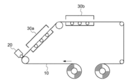
- FIG. 1 is a schematic view showing each step of the method for producing a coating film of one embodiment.
- FIG. 2 is a schematic top view for explaining the film surface temperature of the coating liquid film formed on the support.
- FIG. 3 is a graph for explaining the film surface temperature in the constant rate drying stage.
- the numerical range indicated by using "-" in the present disclosure means a range including the numerical values before and after "-" as the minimum value and the maximum value, respectively.
- the upper limit value or the lower limit value described in a certain numerical range may be replaced with the upper limit value or the lower limit value of another numerical range described stepwise.
- the upper limit value or the lower limit value described in a certain numerical range may be replaced with the value shown in the examples.
- the "width direction” refers to a direction orthogonal to the longitudinal direction of any of a long support, a coating liquid film, and a coating film.
- the “width direction edge portion” refers to the coating liquid film or the edge portion in the width direction of the coating film, and when the film surface of the coating liquid film or the coating film is viewed from above, the coating area. It is visually recognized as a boundary line between (that is, the coating liquid film or the forming portion of the coating film) and the non-coated area (that is, the exposed portion of the support).
- the "width direction end portion” refers to the coating liquid film or the width direction end portion of the coating film, and the width direction edge portion (specifically, the above-mentioned coated area and non-coated area). (Boundary line with) to 20 mm toward the center in the width direction. In the present disclosure, a combination of two or more preferred forms or embodiments is a more preferred embodiment or embodiment.
- this is a method of manufacturing a coating film on a support that is continuously conveyed, and is a step of applying a water-based coating liquid onto a support having high thermal conductivity to form a coating liquid film.
- the method for producing a coating film which comprises a step of drying the formed coating liquid film, cracks may occur at the widthwise end portion of the obtained coating film.
- a support having excellent thermal conductivity such as metal is used as the support for forming the coating film, and the coating liquid is used. This is a phenomenon that occurs when a water-based coating liquid in which the solvent or dispersion medium is substantially water is used.
- a long support having a thermal conductivity of 200 W / (m ⁇ K) or more is continuously conveyed, and a water-based coating liquid is applied onto the continuously conveyed support.
- the step A includes the step A of coating and the step B of drying the coating liquid film obtained in the step A on the support that is continuously conveyed, and the step B includes the following conditions (1) and (2).
- Condition (1) The film surface temperature at a position 5 mm from the widthwise edge of the coating liquid film at T0% when the constant drying is started is set to A (T0%) , and the center in the width direction of the coating liquid film.
- the film surface temperature of the part is B (T0%)
- the film surface temperature at a position 5 mm from the widthwise edge of the coating liquid film at T90% after 90% of the constant drying time is A (T90). %)
- the film surface temperature B (T90%) at the center of the coating liquid film in the width direction ⁇ T [° C.] obtained from the following formula (A) is ⁇ 10 ° C. ⁇ T ⁇ 0 ° C. ..
- Formula (A) ⁇ T [° C.] (A (T0%) -B (T0%) )-(A (T90%) -B (90%) )
- Condition (2) The average value of the film surface temperature A (T0%) , the film surface temperature B (T0%) , the film surface temperature A (T90%) , and the film surface temperature B (T90%) is 35 ° C. or higher. ..
- step A when the tip of the wound long support 10 is sent out and continuous transportation is started, the water-based coating liquid is applied by the coating means 20 (step A).
- step A a coating liquid film of the water-based coating liquid is formed on the long support.
- step B the coating liquid film is dried on the support 10 by continuously transporting the support 10 having the coating liquid film formed in the step A through the drying means 30a and 30b (step).
- step B the coating liquid film on the long support is dried and the coating film is formed.
- step A a long support having a thermal conductivity of 200 W / (m ⁇ K) or more is continuously conveyed, and a water-based coating liquid is applied onto the continuously conveyed support.
- the water-based coating liquid refers to a coating liquid in which the solvent (or dispersion medium) contained in the coating liquid is substantially water.
- the solvent (or dispersion medium) is substantially water means that the inclusion of a solvent other than water introduced when the solid content is used is allowed, and the total solvent (or total dispersion medium) contains.
- the ratio of water in the total solvent (or total dispersion medium) is preferably 95% by mass or more, and the total solvent (or total dispersion medium) is water. Is particularly preferred.
- the solid content refers to a component excluding a solvent (or a dispersion medium).
- the long support used in this step is a support having a thermal conductivity of 200 W / (m ⁇ K) or more.
- the support used in this step is, for example, a support having a multi-layer structure including a metal foil and a resin film, the support as a whole has a thermal conductivity of 200 W / (m ⁇ K) or more. Just do it.
- the upper limit of the thermal conductivity of the support is not particularly limited, and is, for example, 500 W / (m ⁇ K).
- the support exhibiting the thermal conductivity include copper, aluminum, silver, gold, and a metal support made of an alloy thereof.
- a copper support and an aluminum support are preferably used from the viewpoints of shape stability as a support, a track record of use, and the like.
- the thermal conductivity of the support is measured as follows. First, the support is cut out to a size suitable for the device described later to obtain a sample for measurement. With respect to the obtained measurement sample, the thermal diffusivity in the thickness direction is measured by a laser flash method using "LFA467” manufactured by NETZSCH. Next, the specific gravity of the measurement sample is measured using the balance "XS204" (using the “solid density measurement kit") of METTLER TOLEDO Co., Ltd. Further, using "DSC320 / 6200" of Seiko Instruments Inc., the specific heat of the measurement sample at 25 ° C. is determined using the software of DSC7 under the heating condition of 10 ° C./min. The thermal conductivity of the measurement sample (that is, the support) is calculated by multiplying the obtained thermal diffusivity by the specific gravity and the specific heat.
- the thickness of the support may be appropriately set from the viewpoint of applying to the roll-to-roll method.
- the thickness of the support is, for example, preferably 5 ⁇ m to 100 ⁇ m, and more preferably 10 ⁇ m to 30 ⁇ m.
- the width and length of the support may be appropriately set from the viewpoint of applying to the roll-to-roll method and the width and length of the target coating film.
- the thickness of the support is measured as follows. That is, using a contact-type thickness measuring machine, the thickness of the support at three points in the width direction (that is, the position 5 mm from both edges in the width direction and the center part in the width direction) is separated by 500 mm in the longitudinal direction. Measure 3 points. The arithmetic mean value of a total of nine measured values is obtained, and this is used as the thickness of the support.
- the contact type thickness measuring machine for example, S-2270 of Fujiwork Co., Ltd. is used.
- the water-based coating liquid used in this step is not particularly limited as long as it is a liquid material containing water as a solvent (or dispersion medium) and a solid content.
- the solid content contained in the water-based coating liquid includes a component for obtaining a target coating film, a component for improving coating suitability, and the like.
- Examples of the water contained in the water-based coating liquid include natural water, purified water, distilled water, ion-exchanged water, pure water, ultra-pure water (for example, Milli-Q water) and the like.
- the Milli-Q water is ultrapure water obtained by the Milli-Q water production apparatus of Merck Millipore Co., Ltd.
- the content of water in the water-based coating liquid is not particularly limited, and is preferably 40% by mass or more, more preferably 50% by mass or more, based on the total mass of the water-based coating liquid, for example.
- the upper limit of the water content may be less than 100% by mass, but for example, from the viewpoint of coating suitability, it is 90% by mass with respect to the total mass of the water-based coating liquid.
- the water-based coating liquid may contain particles as one of the solid contents. That is, the water-based coating liquid may be a coating liquid containing particles.
- agglutination of particles is also added at the constant rate drying stage, so that the widthwise end portion of the coating film tends to be cracked.
- the particles are not particularly limited as long as they are granular particles, and may be inorganic particles, organic particles, or composite particles of an inorganic substance and an organic substance.
- the inorganic particles known inorganic particles that can be applied to the target coating film can be used.
- the inorganic particles include metal (alkali metal, alkaline earth metal, transition metal, etc. and alloys of these metals) particles, metalloid (silicon, etc.) particles, or metal or metalloid compounds (oxides). , Hydroxide, nitride, etc.) particles, pigment particles containing carbon black and the like, and the like.
- Other examples of the inorganic particles include mineral particles such as mica and inorganic pigment particles.
- organic particles known organic particles applicable to the target coating film can be used.
- the organic particles are not particularly limited as long as they are solid organic particles such as resin particles and organic pigment particles.
- the composite particles of the inorganic substance and the organic substance As the composite particles of the inorganic substance and the organic substance, the composite particles in which the inorganic particles are dispersed in the matrix of the organic substance, the composite particles in which the periphery of the organic particles is coated with the inorganic substance, and the periphery of the inorganic particles are coated with the organic substance.
- Examples include composite particles.
- the particles may be surface-treated for the purpose of imparting dispersibility and the like.
- the composite particles may be formed as described above by being subjected to surface treatment.
- particle size there are no particular restrictions on the particle size, specific gravity, usage pattern (for example, the presence or absence of combined use, etc.) of the particles, depending on the target coating film or the conditions suitable for producing the coating film. , It may be selected as appropriate.
- the content of the particles in the water-based coating liquid is not particularly limited, and is appropriately determined according to the target coating film, the conditions suitable for producing the coating film, or the purpose of adding the particles. , Should be decided.
- the more particles are contained in the water-based coating film the more conspicuous (that is, visually recognizable) the cracks at the widthwise end of the coating film tend to be.
- the method for producing a coating film according to the present embodiment cracking of the widthwise end portion of the coating film is suppressed even if the content of particles in the water-based coating liquid is, for example, 50% by mass or more. can do.
- the solid content contained in the water-based coating liquid is not particularly limited, and examples thereof include various components used to obtain the desired coating film. Specifically, as the solid content contained in the water-based coating liquid, in addition to the above-mentioned particles, a binder component, a component contributing to the dispersibility of the particles, a polymerizable compound, a reactive component such as a polymerization initiator, a surfactant, etc. Ingredients for enhancing the coating performance of the above, other additives and the like can be mentioned.
- the thickness of the coating liquid film formed in this step is not particularly limited, and may be appropriately determined according to the target coating film.
- the thickness of the coating liquid film formed in this step is At at a position 5 mm from the widthwise edge of the coating liquid film, and Bt is the thickness at the center of the coating liquid film in the width direction.
- the coating according to the present embodiment when the difference in thickness between the thickness At and the thickness Bt is small, that is, when a coating liquid film having a thickness close to uniform in the plane is formed, the coating according to the present embodiment.
- the film manufacturing method By applying the film manufacturing method, cracking at the widthwise end portion of the coating film can be effectively suppressed.
- the thickness At and the thickness Bt of the coating liquid film are different. May be.
- the film surface temperature and the amount of change thereof in the step B described later also change due to the difference in the thickness. Therefore, in step B, ⁇ T may be controlled according to the change in the film surface temperature.
- the thickness At and the thickness Bt are measured as follows. First, as the thickness At, an optical interferometry type thickness measuring machine is used to select one from the widthwise edges of the two coating liquid films, and from the selected edges to the center of the coating liquid film in the width direction. The thickness of the coating liquid film at a position of 5 mm is measured at three points with an interval of 500 mm in the longitudinal direction. The arithmetic mean value of the measured values of the three measured points is obtained, and this is defined as the thickness At. Further, as the thickness Bt, a light interference type thickness measuring machine is used to measure the thickness of the central portion of the coating liquid film in the width direction at three points with an interval of 500 mm in the longitudinal direction.
- the arithmetic mean value of the measured values of the three measured points is obtained, and this is defined as the thickness Bt.
- the optical interferometry type thickness measuring device for example, an infrared spectroscopic interferometry film thickness meter SI-T80 manufactured by KEYENCE Corporation can be used.
- the coating width (that is, the width of the coating liquid film) in this step is not particularly limited, and a coating width in which cracks are likely to occur may be applied to the end portion of the manufactured coating film in the width direction.
- the coating width is, for example, preferably 30 mm or more, more preferably 50 mm or more, and further preferably 100 mm or more.
- the upper limit of the coating width is the width of the support.
- the width of the non-coated area (that is, the width of the exposed portion of the support), which is the distance from the widthwise edge of the support to the coating liquid film, is From the viewpoint that the effect of the coating film manufacturing method according to the present embodiment can be easily obtained, it is preferably 2 mm or more, and more preferably 5 mm or more, respectively, at both ends in the width direction.
- the coating width is measured as follows. That is, the film surface of the coating liquid film is viewed from above, and the width of the coating liquid film is measured at three points with a ruler at intervals of 500 mm in the longitudinal direction. Obtain the arithmetic mean value of the measured values of the three measured points, and use this as the coating width.
- a known coating means is applied to the coating of the coating liquid in this step.
- the coating means include a curtain coating method, a dip coating method, a spin coating method, a print coating method, a spray coating method, a slot coating method, a roll coating method, and a slide coating method.
- examples thereof include a coating device using a method, a blade coating method, a gravure coating method, a wire bar method, or the like.
- step B the coating liquid film obtained in step A is dried on the support that is continuously conveyed. Then, the step B includes a constant rate drying step of the coating liquid film satisfying the conditions (1) and (2) described later.
- Drying in this step refers to the process until the coating liquid film formed in step A reaches the target solid content concentration through the constant rate drying step and the reduced rate drying step.
- Constant drying is a form of drying in which the content of the solvent (or dispersion medium) in the coating liquid film decreases with time.
- the coating liquid film exhibits constant rate drying from immediately after formation until a certain period of time elapses, and then exhibits rate reduction drying.
- the time indicating constant drying is described in, for example, the Chemical Engineering Handbook (pages 707 to 712, published by Maruzen Co., Ltd., October 25, 1980).
- the change over time in the film surface temperature (film surface temperature B described later) at the center of the formed coating liquid film in the width direction is measured, and the film surface temperature immediately after coating (immediately after the formation of the coating liquid film).
- the period during which the film surface temperature shows a constant value is regarded as the “constant drying stage”.
- the period in which the film surface temperature shows a constant value is regarded as the "declining rate drying stage”.
- the film surface temperature is measured with a non-contact radiation thermometer.
- step B the drying temperature may be changed stepwise or continuously toward the transport direction of the coating liquid film.
- the film surface temperature of the coating liquid film is also affected and changes. Therefore, in step B, the period in which the film surface temperature of the coating liquid film changes to the same extent as the amount of change in the drying temperature is included in the "period in which the film surface temperature shows a constant value". That is, until the film surface temperature of the coating liquid film rises beyond the amount of change in the drying temperature, it is regarded as a constant rate drying stage.
- the drying in this step includes a constant drying step that satisfies the conditions (1) and (2).
- the conditions (1) and (2) will be described.
- Condition (1) The film surface temperature at a position 5 mm from the widthwise edge of the coating liquid film at T0% when the constant drying is started is set to A (T0%) , and the center in the width direction of the coating liquid film.
- the film surface temperature of the part is B (T0%)
- the film surface temperature at a position 5 mm from the widthwise edge of the coating liquid film at T90% after 90% of the constant drying time is A (T90). %)
- the film surface temperature B (T90%) at the center of the coating liquid film in the width direction ⁇ T [° C.] obtained from the following formula (A) is ⁇ 10 ° C. ⁇ T ⁇ 0 ° C. ..
- Formula (A) ⁇ T [° C.] (A (T0%) -B (T0%) )-(A (T90%) -B (90%) )
- FIG. 2 is a schematic top view for explaining the film surface temperature of the coating liquid film formed on the support.
- FIG. 3 is a graph for explaining the film surface temperature in the constant rate drying stage.
- FIGS. 2 and 3 show a case where the drying temperature is constant during the step B.
- the film surface temperature A at a position 5 mm from the widthwise edge indicated by LA and the widthwise central portion indicated by LB.
- the time-dependent changes in the film surface temperature B and the film surface temperature B are measured, and the relationship between the film surface temperatures A and B and the elapsed time is graphed as shown in FIG.
- the film surface temperature A is selected from the widthwise edges of the two coating liquid films 40, and is located at a position of 5 mm from the selected edges toward the center of the coating liquid film 40 in the width direction.
- the film surface temperature. As shown in FIG. 3, in the graph, in the measurement of the film surface temperature B immediately after coating (immediately after the formation of the coating liquid film), the period during which the film surface temperature B shows a constant value (specifically, The period during which the temperature change of the film surface temperature is within ⁇ 5 ° C.) is regarded as the constant drying stage.
- the change point of the film surface temperature B at which the film surface temperature B starts to rise is set as the end point of the constant rate drying step (T100% in FIG. 3).
- the change points are a straight line (dotted line x in FIG. 3) extending the film surface temperature B during the period showing a constant value to the elapsed time side (right side in FIG. 3) and a gradient of the film surface temperature B. It is obtained from the intersection with the tangent line (dotted line y in FIG. 3) drawn at the point where is maximum. Then, the period from the start point of the period in which the film surface temperature B shows a constant value to the change point of the film surface temperature B is defined as the constant rate drying time.
- the start point of the period in which the film surface temperature B shows a constant value is set as "the time at T0% when the constant rate drying is started", and from the start point to the end point (T100% in FIG. 3) of this period.
- the point where 90% has passed with respect to the entire period is defined as "the time at T90% when 90% of the constant drying time has passed”.
- the film surface temperature A (T0%) and the film surface temperature B (T0%) at the time of T0% when the constant rate drying was started were obtained, and further, the constant rate drying time of 90.
- the film surface temperatures A (T90%) and B (T90%) at the time of T90% after% has passed are determined.
- the ⁇ T obtained as described above needs to be more than ⁇ 10 ° C. and lower than 0 ° C. Since the film surface temperature B at the central portion in the width direction of the coating liquid film 40 as shown in FIG. 2 is not easily affected by the thermal conductivity of the support, it is unlikely to increase with time. On the other hand, the film surface temperature A at a position 5 mm from the widthwise edge of the coating liquid film 40 is easily affected by the support exposed in the non-coated area, and even in the constant drying stage. , There may be an increase over time. When the film surface temperature A rises remarkably with time in the constant rate drying step, ⁇ T [° C.] obtained from the formula (A) does not satisfy ⁇ 10 ° C. ⁇ T ⁇ 0 ° C.
- the drying proceeds only at the widthwise end portion of the coating liquid film 40. It is presumed that cracks occur at the widthwise end of the obtained coating film.
- ⁇ T [° C.] satisfies ⁇ 10 ° C. ⁇ T ⁇ 0 ° C. means that a significant increase in the film surface temperature A in the coating liquid film 40 with time is suppressed. That is, if the significant increase in the film surface temperature A with time is suppressed, it is considered that the drying progresses only at the widthwise end portion of the coating liquid film 40, and thus it is obtained through this step.
- ⁇ T [° C.] may be ⁇ 8 ° C.
- ⁇ T [° C.] may be ⁇ 6 ° C.
- ⁇ T [° C.] may be -4 ° C. ⁇ T ⁇ 0 ° C.
- Condition (2) The average value of the film surface temperature A (T0%) , the film surface temperature B (T0%) , the film surface temperature A (T90%) , and the film surface temperature B (T90%) is 35 ° C. or higher. ..
- the values of the film surface temperature A (T0%) , the film surface temperature B (T0%) , the film surface temperature A (T90%) , and the film surface temperature B (T90%) are shown in the graph as shown in FIG. Just ask.
- the average values of the film surface temperature A (T0%) , the film surface temperature B (T0%) , the film surface temperature A (T90%) , and the film surface temperature B (T90%) were obtained from the graph 4
- the condition (2) indicates a condition in which the end portion in the width direction of the coating film is likely to be cracked.
- the above-mentioned condition (1) is also satisfied. Therefore, the width direction of the coating film obtained through this step is satisfied. Cracks that occur at the edges are suppressed.
- the upper limit of the average value of the above-mentioned film surface temperature in the constant rate drying stage is not limited.
- the upper limit of the average value of the film surface temperature in the constant rate drying step may be, for example, 90 ° C., 80 ° C., 70 ° C., 60 ° C., 50 ° C. or 40 ° C.
- a known drying means is applied to the drying of the coating liquid film.
- the drying means include an oven, a hot air blower, an infrared (IR) heater, and the like.
- the drying means for satisfying the conditions (1) and (2) particularly the drying means for controlling ⁇ T
- the following means can be mentioned.
- a warm air blower change the wind speed of the warm air blown to the coating liquid film and the wind speed of the warm air blown to the non-coating area (exposed part of the support) of the coating liquid film (for example, the coating liquid).
- the wind speed of the warm air blown to the uncoated area (exposed part of the support) is made smaller).
- a warm air blower change the temperature of the hot air blown on the coating liquid film and the temperature of the hot air blown on the non-coated area (exposed part of the support) (for example, the hot air blown on the coating liquid film).
- the temperature of the hot air blown to the uncoated area (exposed part of the support) is lower than the temperature of (or the hot air blown to the uncoated area (exposed part of the support) is cold air below room temperature. ).
- the drying means for satisfying the above conditions (1) and (2), particularly the drying means for controlling ⁇ T may be applied immediately after the coating liquid film is formed in the step A, or may be constantly applied. It may be applied from the rate drying stage. Further, the drying means for satisfying the above conditions (1) and (2), particularly the drying means for controlling ⁇ T, continues during the constant rate drying stage (that is, from the time T0% to the time T100%). Is preferable.
- the following means can be mentioned. -Apply water of the same thickness as the coating liquid film to the non-coated area of the coating liquid film (that is, the support is not exposed to the non-coated area of the coating liquid film). -The non-coated area of the coating liquid film is not formed or reduced (for example, the shortest distance from both ends of the support in the width direction to both ends of the coating liquid film is 2 mm or less).
- a means for blowing warm air with a warm air blower to the coating liquid film from the viewpoint of satisfying the condition (2) and controlling the drying speed.
- the above-mentioned drying means and various means for satisfying the above-mentioned conditions (1) and (2) may be used alone or in combination of two or more. Further, the drying means, drying conditions, etc. in the constant rate drying step and the reduced rate drying step may be the same or different. If the constant rate drying step satisfying the above conditions (1) and (2) is passed, even if the drying means, drying conditions, etc. in the rate reduction drying step are changed, the cracks generated at the end in the width direction are affected. Hard to exert.
- a coating film is formed on the support through step B.
- the thickness of the coating film obtained through the step B is not particularly limited, and may be any thickness according to the purpose, application, and the like.
- the thickness of the coating film is preferably 40 ⁇ m or more, more preferably 50 ⁇ m or more, and further preferably 60 ⁇ m or more.
- the upper limit of the thickness of the coating film is not particularly limited and may be determined according to the intended use, but is, for example, 300 ⁇ m.
- the measurement of the thickness of the coating film is the same as the measurement of the thickness of the coating liquid film.
- step A and at least one after step B may be provided before step A and at least one after step B.
- the other steps are not particularly limited, and include a pretreatment step performed before applying the coating liquid film, a posttreatment step performed on the formed coating film depending on the use of the coating film, and the like. Be done.
- steps specifically, a step of surface-treating the support, a step of curing the coating film, a step of compressing the coating film, a step of cutting the coating film, and a step of removing the support from the coating film. Examples thereof include a peeling step.
- the method for producing a coating film according to the present embodiment is a method for producing a coating film on a support that is continuously conveyed, it is suitable for producing a coating film for applications requiring high productivity.
- An aluminum support 1 (thermal conductivity: 230 W / (m ⁇ K)) having a width of 220 mm, a thickness of 20 ⁇ m, and a length of 300 m was prepared (abbreviated as AL1).
- An aluminum support 2 (thermal conductivity: 230 W / (m ⁇ K)) having a width of 203 mm, a thickness of 20 ⁇ m, and a length of 300 m was prepared (abbreviated as AL2).
- ⁇ Preparation of water-based coating liquid> [Preparation of water-based coating liquid A] The following components were mixed to prepare a water-based coating liquid A.
- -Polyvinyl alcohol 58 parts (CKS-50: 99 mol% saponification degree, degree of polymerization 300, Nippon Synthetic Chemical Industry Co., Ltd.)
- Serogen PR of Dai-ichi Kogyo Seiyaku Co., Ltd . 24 parts
- Surfactant Nippon Emulsion Co., Ltd., Emarex 710: 5 parts
- the mixture was dispersed for 15 minutes with revolutions per minute; the same applies hereinafter) to obtain an aqueous dispersion of Artpearl J-7P (particle concentration: 20% by mass).
- the true specific gravity of the silica composite crosslinked acrylic resin fine particles in the obtained aqueous dispersion is 1.20, and the average particle size is 6.5 ⁇ m.
- -Dispersion A prepared by the following method: 132.1 parts-Dispersion B prepared by the following method: 396.2 parts-Boric acid (crosslinking agent): 2.94 parts-Polyvinyl alcohol (7.3 mass) % Aqueous solution): 230.7 parts (Kuraray Co., Ltd., PVA 235, saponification degree 88%, polymerization degree 3500) -Diethylene glycol monobutyl ether: 2.7 parts (Buchisenol 20-P, KH Neochem Co., Ltd.) -Ion-exchanged water: 93.5 parts-Polyoxyethylene lauryl ether (surfactant): 0.49 parts (10% by mass aqueous solution of Emulgen 109P, HLB value 13.6, Kao Corporation) ⁇ Ethanol: 41.4 parts
- Example 1 In the apparatus configured as shown in FIG. 1, a water-based coating liquid A is applied onto the aluminum support 1 to form a coating liquid film, and the formed coating liquid film is dried for coating. A membrane was obtained. Specifically, the water-based coating liquid A was applied onto the support that was continuously conveyed (step A). The coating width and thickness of the formed coating liquid film are as shown in Table 1. Subsequently, warm air was blown using a warm air blower, and the coating liquid film was dried using the ⁇ T control means shown in Table 1 (step B). The blowing of warm air using a warm air blower and the drying by the ⁇ T control means continued during the constant rate drying stage (that is, from the time of T0% to the time of T100%).
- step A and step B The transport speed of the support in step A and step B was 20 m / min. As described above, the coating film was formed through the steps A and B.
- Example 2 A coating film was formed in the same manner as in Example 1 except that the specific means for drying the coating liquid film in step B was changed as shown in Table 1. In Example 4, the aluminum support 2 was used instead of the aluminum support 1.
- Example 7 to 13 The coating film was prepared in the same manner as in Example 1 except that the coating width of the coating liquid film formed in the step A and the thickness of the coating liquid film were appropriately changed as shown in Table 1. Formed.
- Examples 14 to 19 A coating film was formed in the same manner as in each of Examples 1 to 6 except that the water-based coating liquid A was changed to the water-based coating liquid B.
- step B in addition to the coating liquid film, the non-coating area of the coating liquid film was also blown with the same warm air as the coating liquid film, except that the ⁇ T control means was not adopted.
- a coating film was formed in the same manner as in each of 5, 6 and 14.
- a polyethylene terephthalate (PET) support (thermal conductivity: 0.3 W / (m ⁇ K)) having a width of 220 mm, a thickness of 38 ⁇ m, and a length of 300 m was used, and further coated in step B.
- the non-coated area of the coating liquid film is also coated in the same manner as in Example 1 except that the same warm air as that of the coating liquid film is applied and the ⁇ T control means is not adopted. A film was formed.
Landscapes
- Life Sciences & Earth Sciences (AREA)
- Engineering & Computer Science (AREA)
- Wood Science & Technology (AREA)
- Application Of Or Painting With Fluid Materials (AREA)
- Drying Of Solid Materials (AREA)
Abstract
Priority Applications (3)
| Application Number | Priority Date | Filing Date | Title |
|---|---|---|---|
| KR1020227034415A KR102821977B1 (ko) | 2020-04-06 | 2021-03-26 | 도공막의 제조 방법 |
| CN202180026824.4A CN115443195B (zh) | 2020-04-06 | 2021-03-26 | 涂布膜的制造方法 |
| JP2022514415A JP7358631B2 (ja) | 2020-04-06 | 2021-03-26 | 塗工膜の製造方法 |
Applications Claiming Priority (2)
| Application Number | Priority Date | Filing Date | Title |
|---|---|---|---|
| JP2020068517 | 2020-04-06 | ||
| JP2020-068517 | 2020-04-06 |
Publications (1)
| Publication Number | Publication Date |
|---|---|
| WO2021205920A1 true WO2021205920A1 (fr) | 2021-10-14 |
Family
ID=78023034
Family Applications (1)
| Application Number | Title | Priority Date | Filing Date |
|---|---|---|---|
| PCT/JP2021/013082 Ceased WO2021205920A1 (fr) | 2020-04-06 | 2021-03-26 | Procédé pour la production d'un film de revêtement |
Country Status (4)
| Country | Link |
|---|---|
| JP (1) | JP7358631B2 (fr) |
| KR (1) | KR102821977B1 (fr) |
| CN (1) | CN115443195B (fr) |
| WO (1) | WO2021205920A1 (fr) |
Cited By (2)
| Publication number | Priority date | Publication date | Assignee | Title |
|---|---|---|---|---|
| JP2025033210A (ja) * | 2023-08-29 | 2025-03-13 | トヨタ自動車株式会社 | 電極の製造方法 |
| JP2025121800A (ja) * | 2024-02-07 | 2025-08-20 | トヨタ自動車株式会社 | 電極の製造方法、及び蓄電装置の製造方法 |
Citations (5)
| Publication number | Priority date | Publication date | Assignee | Title |
|---|---|---|---|---|
| JP2002273308A (ja) * | 2001-03-15 | 2002-09-24 | Matsushita Electric Ind Co Ltd | 乾燥状態測定装置およびそれを備えた塗膜乾燥機 |
| JP2002340479A (ja) * | 2001-05-21 | 2002-11-27 | Dainippon Printing Co Ltd | 乾燥装置 |
| JP2010240560A (ja) * | 2009-04-03 | 2010-10-28 | Fujifilm Corp | 記録用シートの製造方法及び装置 |
| JP2013086286A (ja) * | 2011-10-14 | 2013-05-13 | Nec Tokin Corp | セラミックグリーンシートの製造方法および製造装置 |
| JP2016160548A (ja) * | 2015-03-02 | 2016-09-05 | 日本製紙株式会社 | キャストコータ及びキャストコート紙の製造方法 |
Family Cites Families (9)
| Publication number | Priority date | Publication date | Assignee | Title |
|---|---|---|---|---|
| JPH11342533A (ja) * | 1998-06-01 | 1999-12-14 | Toray Ind Inc | 熱可塑性樹脂フイルムの製造方法 |
| JP2004268392A (ja) | 2003-03-07 | 2004-09-30 | Fuji Photo Film Co Ltd | インクジェット記録用シートの製造方法及び塗布膜の乾燥装置 |
| JP2006187883A (ja) | 2004-12-28 | 2006-07-20 | Fuji Photo Film Co Ltd | 記録媒体及びその製造方法 |
| JP5114108B2 (ja) * | 2007-06-27 | 2013-01-09 | 富士フイルム株式会社 | 塗布膜の乾燥方法及び装置 |
| CN202410957U (zh) * | 2011-10-24 | 2012-09-05 | 深圳市浩能科技有限公司 | 涂布机热风烘干机及其专用异型风嘴 |
| CN102989647B (zh) * | 2012-12-14 | 2014-08-06 | 武汉钢铁(集团)公司 | 一种复合式烘干取向硅钢板绝缘涂层的方法 |
| CN203316364U (zh) * | 2013-05-29 | 2013-12-04 | 宁德新能源科技有限公司 | 涂布机烘箱装置 |
| JP2016066460A (ja) | 2014-09-24 | 2016-04-28 | トヨタ自動車株式会社 | 負極の製造方法 |
| JP6942654B2 (ja) * | 2018-02-23 | 2021-09-29 | 株式会社Screenホールディングス | 塗工装置および塗工方法 |
-
2021
- 2021-03-26 WO PCT/JP2021/013082 patent/WO2021205920A1/fr not_active Ceased
- 2021-03-26 KR KR1020227034415A patent/KR102821977B1/ko active Active
- 2021-03-26 JP JP2022514415A patent/JP7358631B2/ja active Active
- 2021-03-26 CN CN202180026824.4A patent/CN115443195B/zh active Active
Patent Citations (5)
| Publication number | Priority date | Publication date | Assignee | Title |
|---|---|---|---|---|
| JP2002273308A (ja) * | 2001-03-15 | 2002-09-24 | Matsushita Electric Ind Co Ltd | 乾燥状態測定装置およびそれを備えた塗膜乾燥機 |
| JP2002340479A (ja) * | 2001-05-21 | 2002-11-27 | Dainippon Printing Co Ltd | 乾燥装置 |
| JP2010240560A (ja) * | 2009-04-03 | 2010-10-28 | Fujifilm Corp | 記録用シートの製造方法及び装置 |
| JP2013086286A (ja) * | 2011-10-14 | 2013-05-13 | Nec Tokin Corp | セラミックグリーンシートの製造方法および製造装置 |
| JP2016160548A (ja) * | 2015-03-02 | 2016-09-05 | 日本製紙株式会社 | キャストコータ及びキャストコート紙の製造方法 |
Cited By (2)
| Publication number | Priority date | Publication date | Assignee | Title |
|---|---|---|---|---|
| JP2025033210A (ja) * | 2023-08-29 | 2025-03-13 | トヨタ自動車株式会社 | 電極の製造方法 |
| JP2025121800A (ja) * | 2024-02-07 | 2025-08-20 | トヨタ自動車株式会社 | 電極の製造方法、及び蓄電装置の製造方法 |
Also Published As
| Publication number | Publication date |
|---|---|
| KR20220145907A (ko) | 2022-10-31 |
| JPWO2021205920A1 (fr) | 2021-10-14 |
| CN115443195A (zh) | 2022-12-06 |
| JP7358631B2 (ja) | 2023-10-10 |
| KR102821977B1 (ko) | 2025-06-17 |
| CN115443195B (zh) | 2024-01-02 |
Similar Documents
| Publication | Publication Date | Title |
|---|---|---|
| JP7358631B2 (ja) | 塗工膜の製造方法 | |
| JP5395656B2 (ja) | 透明な被覆 | |
| EP4369428B1 (fr) | Procédé de formation de film de revêtement | |
| JP7446412B2 (ja) | 塗工膜の製造方法 | |
| CN103476595A (zh) | 印刷用片及用于在该印刷用片上形成印刷面的模具材料片 | |
| JP7252941B2 (ja) | 炭化ケイ素焼結体用分散体、これを用いた炭化ケイ素焼結体用グリーンシートおよび炭化ケイ素焼結体用プリプレグ材、ならびにその製造方法 | |
| TW201903076A (zh) | 導電性墨水及導電性基板的製造方法 | |
| JP5529435B2 (ja) | 多孔質シートの製造方法及び多孔質シート | |
| JP2016150473A (ja) | 粗面化フィルム及びその製造方法 | |
| WO2023145842A1 (fr) | Dispositif de séchage et procédé de séchage | |
| US20120308775A1 (en) | Hydrophilic surfaces and process for preparing | |
| JP7758689B2 (ja) | 積層体の製造方法 | |
| JP7812804B2 (ja) | 積層体の製造方法 | |
| TW202510966A (zh) | 塗布膜的製造方法 | |
| WO2022130902A1 (fr) | Procédé de production de film multicouche et dispositif de revêtement | |
| JP5089068B2 (ja) | 定着用回転体及びその製造方法 | |
| JP2011033243A (ja) | 熱交換器用フィン材 | |
| WO2023032852A1 (fr) | Filière d'extrusion, dispositif de revêtement et procédé de fabrication de film de revêtement | |
| CN108276012A (zh) | 一种用于铸造行业的不粘铝涂料 | |
| JP2026025988A (ja) | 加熱ローラ | |
| WO2025005148A1 (fr) | Composition d'apprêt aqueuse, procédé de formation d'une couche d'apprêt et article moulé | |
| JP2024017543A (ja) | 導電膜の形成方法と光焼成用導電性インク | |
| JPS6085913A (ja) | 表面粗さを有するポリビニルブチラ−ルフイルムの製造方法 | |
| JP2005046706A (ja) | 塗布層体の製造方法 | |
| JP2004233400A (ja) | 加熱式定着ローラ及び加熱式定着ローラの製造方法 |
Legal Events
| Date | Code | Title | Description |
|---|---|---|---|
| 121 | Ep: the epo has been informed by wipo that ep was designated in this application |
Ref document number: 21784248 Country of ref document: EP Kind code of ref document: A1 |
|
| ENP | Entry into the national phase |
Ref document number: 2022514415 Country of ref document: JP Kind code of ref document: A |
|
| ENP | Entry into the national phase |
Ref document number: 20227034415 Country of ref document: KR Kind code of ref document: A |
|
| NENP | Non-entry into the national phase |
Ref country code: DE |
|
| 122 | Ep: pct application non-entry in european phase |
Ref document number: 21784248 Country of ref document: EP Kind code of ref document: A1 |