WO2021255890A1 - Chemise striée, son procédé de fabrication, et procédé de discrimination de résistance d'assemblage - Google Patents
Chemise striée, son procédé de fabrication, et procédé de discrimination de résistance d'assemblage Download PDFInfo
- Publication number
- WO2021255890A1 WO2021255890A1 PCT/JP2020/023956 JP2020023956W WO2021255890A1 WO 2021255890 A1 WO2021255890 A1 WO 2021255890A1 JP 2020023956 W JP2020023956 W JP 2020023956W WO 2021255890 A1 WO2021255890 A1 WO 2021255890A1
- Authority
- WO
- WIPO (PCT)
- Prior art keywords
- liner
- spiny
- protrusions
- constricted
- average
- Prior art date
- Legal status (The legal status is an assumption and is not a legal conclusion. Google has not performed a legal analysis and makes no representation as to the accuracy of the status listed.)
- Ceased
Links
Images


Classifications
-
- F—MECHANICAL ENGINEERING; LIGHTING; HEATING; WEAPONS; BLASTING
- F02—COMBUSTION ENGINES; HOT-GAS OR COMBUSTION-PRODUCT ENGINE PLANTS
- F02F—CYLINDERS, PISTONS OR CASINGS, FOR COMBUSTION ENGINES; ARRANGEMENTS OF SEALINGS IN COMBUSTION ENGINES
- F02F1/00—Cylinders; Cylinder heads
- F02F1/004—Cylinder liners
-
- B—PERFORMING OPERATIONS; TRANSPORTING
- B22—CASTING; POWDER METALLURGY
- B22D—CASTING OF METALS; CASTING OF OTHER SUBSTANCES BY THE SAME PROCESSES OR DEVICES
- B22D15/00—Casting using a mould or core of which a part significant to the process is of high thermal conductivity, e.g. chill casting; Moulds or accessories specially adapted therefor
- B22D15/02—Casting using a mould or core of which a part significant to the process is of high thermal conductivity, e.g. chill casting; Moulds or accessories specially adapted therefor of cylinders, pistons, bearing shells or like thin-walled objects
-
- B—PERFORMING OPERATIONS; TRANSPORTING
- B22—CASTING; POWDER METALLURGY
- B22D—CASTING OF METALS; CASTING OF OTHER SUBSTANCES BY THE SAME PROCESSES OR DEVICES
- B22D19/00—Casting in, on, or around objects which form part of the product
- B22D19/0009—Cylinders, pistons
-
- B—PERFORMING OPERATIONS; TRANSPORTING
- B22—CASTING; POWDER METALLURGY
- B22D—CASTING OF METALS; CASTING OF OTHER SUBSTANCES BY THE SAME PROCESSES OR DEVICES
- B22D19/00—Casting in, on, or around objects which form part of the product
- B22D19/08—Casting in, on, or around objects which form part of the product for building-up linings or coverings, e.g. of anti-frictional metal
-
- F—MECHANICAL ENGINEERING; LIGHTING; HEATING; WEAPONS; BLASTING
- F02—COMBUSTION ENGINES; HOT-GAS OR COMBUSTION-PRODUCT ENGINE PLANTS
- F02F—CYLINDERS, PISTONS OR CASINGS, FOR COMBUSTION ENGINES; ARRANGEMENTS OF SEALINGS IN COMBUSTION ENGINES
- F02F2200/00—Manufacturing
Definitions
- the present invention relates to a spiny liner having a protrusion having a new shape on the surface, a method for manufacturing the spiny liner, a method for discriminating the joint strength, and a spiny liner having information on the joint strength.
- the cast iron cylindrical member is used for a cylinder liner of an internal combustion engine, a brake drum of an inscribed drum brake, a bearing member, a support member, and the like.
- the outer peripheral surface of the cast iron cylindrical member is cast and wrapped with a metal material, and the metal on the outer peripheral side and the cast iron cylindrical member are integrated. Then, in order to maintain the joint strength when integrated, a plurality of protrusions are provided on the outer peripheral surface of the cast iron cylindrical member (see, for example, Patent Documents 1 and 2).
- Patent Document 3 focuses on the constricted shape of the protrusion, and is based on the finding that the space between the maximum thickness and the minimum thickness of the protrusion (hereinafter, also referred to as an anchor portion) greatly contributes to the joint strength.
- the present invention is a cylinder liner for casting and wrapping, which is a spiny liner having protrusions on the surface, and which has a new shape of protrusions on the surface, which can further improve the bonding strength when integrated with a metal on the outer peripheral surface side.
- the challenge is to provide.
- the present inventors proceeded with studies to solve the above problems, and controlled the shape of the protrusions in consideration of the strength of each protrusion itself, that is, the value of the minimum thickness of the protrusions, in addition to the anchor portion of the protrusions. By doing so, we found that the above problems could be solved. We also found that by applying this knowledge, it is possible to distinguish the joint strength when integrated.
- An embodiment of the present invention is a spiny liner having a plurality of protrusions including protrusions constricted on the surface.
- the number of constricted protrusions per 100 mm 2 of the protrusions is Pc
- the average height of the protrusions is h (mm)
- the average of the maximum thicknesses of any 20 of the constricted protrusions is dw (mm)
- (I) Pc ⁇ [(0.35h ⁇ / 12) ⁇ (2dw 2- dw ⁇ dn-dn 2 )]
- (II) Pc ⁇ ⁇ ( dn 2 /4) ⁇ 0.35h ⁇
- the dw / dn is preferably 1.1 or more and 1.6 or less, the value of (I) is preferably 0.25 or more, and the value of (II) is 1.35 or more. Is preferable.
- Another embodiment of the present invention is a method for discriminating the bonding strength of a complex when a spiny liner having protrusions on the surface is bonded to a cylinder block. It is a discrimination method including a discrimination step for discriminating whether or not the total value of the following (I) and (II) is 1.55 or more for the protrusions on the surface of the spiny liner. Method of calculating the values of (I) and (II); The number of constricted protrusions Pc per 100 mm 2 , the average height of the protrusions is h (mm), the average of the maximum thickness of any of the 20 constricted protrusions is dw (mm), and the average of the minimum thickness.
- another embodiment of the present invention includes a preparation step for preparing a spiny liner, a discrimination step for discriminating the joint strength of the prepared spiny liner by the method described above, and a total value of (I) and (II) in the discrimination step.
- a method of manufacturing a spiny liner comprising a selection step of selecting a spiny liner having a value of 1.55 or higher.
- Yet another embodiment of the invention is a spiny liner with protrusions on the surface that has information on the bond strength of the composite when joined to the cylinder block, the information being directly imparted to the spiny liner, packaging of the spiny liner.
- the form provided directly to the body or via a medium, or provided by a medium packaged with a spiny liner is preferred.
- a spiny liner capable of further improving the bonding strength when integrated with the metal on the outer peripheral surface side.
- This spiny liner is suitably used when casting by the die casting method.
- the bonding strength when the spiny liner and the metal on the outer peripheral surface side are integrated can be discriminated.
- One embodiment of the present invention is a spiny liner having a plurality of protrusions including protrusions constricted on the surface.
- a cylinder liner having a plurality of protrusions on the surface is referred to as a spiny liner.
- the spiny liner can be used as a cylinder liner in which the piston of an internal combustion engine slides its cylinder bore.
- the present inventors focused on the shape of the protrusions possessed by the spiny liner, and took into consideration the difference between the maximum thickness and the minimum thickness of the protrusions, as well as the strength of each protrusion itself, that is, the value of the minimum thickness of the protrusions.
- the number of constricted protrusions per 100 mm 2 of the protrusions on the surface of the spiny liner is Pc
- the average height of the protrusions is h (mm)
- the maximum thickness of any 20 of the constricted protrusions is It is a spiny liner in which the average is dw (mm) and the average of the minimum thickness is dn (mm), and the total value of the following (I) and (II) is 1.55 or more.
- (I) Pc ⁇ [(0.35h ⁇ / 12) ⁇ (2dw 2- dw ⁇ dn-dn 2 )]
- (II) Pc ⁇ ⁇ ( dn 2 /4) ⁇ 0.35h ⁇
- FIG. 1 is a diagram schematically showing a cross section of a constricted protrusion on the surface of a spiny liner.
- the protrusion 10 has a height H from the basal plane 11 on the outer periphery of the spiny liner, and typically the thickness of the protrusion gradually decreases from the basal plane 11 toward the height direction to have a minimum thickness dN. After that, the thickness gradually increases in the height direction and has a maximum diameter. The thickness of the maximum diameter is called the maximum thickness dW.
- the protrusions having the minimum thickness dN and the maximum thickness dW in this order from the basal plane 11 toward the height direction are referred to as constricted protrusions in the present specification.
- the present inventors have examined the shape of the protrusion in more detail in order to improve the joint strength when the metal on the outer peripheral side such as the cylinder block and the spiny liner are integrated, and determine the maximum and minimum thickness of the protrusion.
- the bonding strength when the metal and spiny liner are integrated is different. This is because the value of dN also greatly contributes to the bonding strength when the metal on the outer peripheral side and the spiny liner are integrated. Therefore, it is necessary to control the protrusion shape in consideration of the value of dN.
- the above formula (I) represents the degree to which the constriction of the protrusion locks with the metal on the outer peripheral side. That is, when the value of the above equation (I) is small, the spiny liner and the metal on the outer peripheral side tend to come off easily.
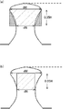
- the formula (I) shows the volume of the region shown by the cross-hatching in FIG. 3 (a), and from the volume of the cylinder whose diameter is dW and whose height is 0.35H, the upper base is dN and the lower base is lower. Is dW and the height is 0.35H, and the volume of the cylindrical trapezoid (the cross section thereof is shown by hatching in the figure) is subtracted.
- the present inventors have found that the distance between the maximum thickness dW and the minimum large thickness dN in the protrusion is 0.35H on average.
- the above equation (II) represents the strength of the protrusion itself. That is, when the value of the above equation (II) is small, the strength of the protrusion itself of the spiny liner tends to decrease, and when a strong shear force or tensile force is generated between the spiny liner and the metal on the outer peripheral side, the protrusion The joint strength tends to decrease due to the breakage.
- the volume of the region shown by (b) hatching in FIG. 3 is shown, and it is the volume of a cylinder having dN as a radius and a height of 0.35H.
- the average of the maximum thickness (dW) of 20 arbitrary protrusions among the constricted protrusions is dw (mm), and the average of the minimum thickness (dN) of 20 arbitrary protrusions among the constricted protrusions is dn (mm). ).
- the total value of the above (I) and (II) is defined as a lock index, and when this lock index is a certain value or more, that is, 1.55 or more, the bonding strength when integrated with the metal on the outer peripheral side is increased. It is possible to provide a spiny liner that can be further improved.
- the lock index is preferably 1.70 or higher, more preferably 2.0 or higher.
- the value of (I) is preferably 0.25 or more, and the value of (II) is preferably 1.35 or more.
- the amount of constriction represented by dw-dn is preferably 0.08 or more, more preferably 0.1 or more, preferably 0.4 or less, and 0.35 or less. Is more preferable.
- the amount of constriction represented by dw-dn is within the above range, the constriction of the protrusion is firmly locked to the metal on the outer peripheral side, and the bonding strength between the spiny liner and the metal on the outer peripheral side thereof is improved.
- dw / dn is preferably 1.18 or more, more preferably 1.2 or more, preferably 1.6 or less, and more preferably 1.5 or less.
- the number of constricted protrusions Pc per 100 mm 2 of the protrusions on the surface of the spiny liner is usually 10 or more, may be 20 or more, may be 30 or more, and is usually 130 or less, and 100 or less. It may be 80 or less. In one form, it may be 10 or more and 40 or less, in another form it may be 30 or more and 50 or less, in another form it may be 40 or more and 80 or less, and in another form it may be 70. The number may be 100 or more and 130 or less.
- the average height h (mm) of the protrusions on the surface of the spiny liner may be usually 0.3 or more, 0.4 or more, 1.0 or less, and 0.9 or less. .. In one form, it may be 0.3 or more and less than 0.6, 0.3 or more and 0.55 or less, 0.3 or more and less than 0.5, and 0.3 or more and 0.5. It may be less than or equal to, and in another form, it may be 0.6 or more and 1.0 or less, and may be 0.6 or more and 0.8 or less.
- the average dw (mm) of the maximum thickness of any 20 of the constricted protrusions is usually 0.4 or more, 0.5 or more, and may be 0.6 or more. Further, it may be usually 1.3 or less, 1.2 or less, or 1.0 or less. In one form, it may be 0.6 or more and 1.0 or less, 0.5 or more and 0.9 or less, and 0.4 or more and 0.8 or less.
- the average dn (mm) of the minimum thickness of any 20 of the constricted protrusions is usually 0.25 or more, 0.3 or more, and may be 0.4 or more. Further, it may be usually 1.2 or less, 1.0 or less, and may be 0.8 or less. In one form, it may be 0.4 or more and 0.8 or less, 0.3 or more and 0.7 or less, and 0.2 or more and 0.6 or less.
- the constriction rate Pr which is the ratio of the number of constricted protrusions to the total number of protrusions Pn per 100 mm 2 of the protrusions on the surface of the spiny liner, is usually 0.5 or more, may be 0.6 or more, and may be 0.7 or more. It may be 0.8 or more, 0.9 or more, 0.92 or more, 0.94 or more, 0.95 or more, 0. It may be .96 or more, 0.97 or more, 0.98 or more, and 0.99 or more.
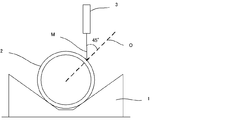
- the constricted protrusions can be determined by observation with a microscope. More specifically, the protrusions are observed on the outer peripheral surface of the spiny liner from an angle of about 45 ° with respect to the line extending through the center point of the cylindrical member and the measurement point of the outer peripheral surface. By changing the observation angle and the focal point, the maximum thickness dW and the minimum thickness dN of the protrusion can be measured. The thickness of the protrusions referred to here can also be rephrased as the width of the observed protrusions. The observation method will be described more specifically with reference to FIG. As shown in FIG. 4, the evaluation spiny liner 2 was placed on the block table 1.
- a microscope 3 connected to a television monitor (not shown) was placed diagonally above the evaluation spiny liner 2 so that the optical axis M of the microscope 3 was parallel to the vertical direction.
- the intersection of the optical axis M of the microscope 3 and the outer peripheral surface of the spiny liner 2 to be measured forms an angle of about 45 ° between the center point of the spiny liner 2 and the line O extending through the measurement point of the outer peripheral surface.
- the protrusions formed on the surface of the spiny liner 2 are observed, but the angle and focus are adjusted so that they can be easily observed.
- the spiny liner of the present embodiment has a composite structure of the spiny liner and the metal on the outer peripheral side thereof by covering at least a part of the outer peripheral surface with the metal, and is used for various purposes as the composite structure.
- the composite structure is preferably a composite structure in which the spiny liner is cast and wrapped in a metal on the outer peripheral side thereof.
- the metal on the outer peripheral side constituting the composite is not particularly limited, but a material that solidifies by cooling from a high temperature state, a liquid material that cures by a polymerization reaction, or a powdery raw material that is fused or sintered by heating is used. Can be used. Typically, a molten metal using an aluminum alloy or the like can be mentioned.
- the spiny liner is typically a member made of cast iron.
- the composition of cast iron which is the material of the spiny liner, is not particularly limited.
- the composition shown below can be exemplified as the composition of the flake graphite cast iron equivalent to JIS FC250 in consideration of wear resistance, seizure resistance and processability.
- P 0.25% by mass or less
- S 0.15% by mass or less
- Cr 0.5% by mass or less
- Remaining Fe and unavoidable impurities
- Step A is a step of blending a refractory base material, a binder, and water in a predetermined ratio to prepare a suspension.
- Diatomaceous earth is typically used as the refractory base material, but the present invention is not limited to this.
- the content of diatomaceous earth in the suspension is usually 62% by mass or more and 91% by mass or less, and the average particle size of diatomaceous earth is usually 3 ⁇ m or more and 40 ⁇ m or less.
- Bentonite is typically used as the binder, but it is not limited to this.
- the liquid temperature of the suspension is preferably 35 ° C. or lower, more preferably 25 ° C. or lower, and even more preferably 15 ° C. or lower.
- the content of bentonite in the suspension is usually 9% by mass or more and 38% by mass or less.
- Step B is a step of adding a predetermined amount of a surfactant to the suspension prepared in Step A to prepare a coating agent.
- the type of the surfactant is not particularly limited, and a known surfactant is used.
- the blending amount of the surfactant is usually 0.01% by mass or more and 0.22% by mass or less.
- Step C is a step of applying a mold coating agent to the inner peripheral surface of a cylindrical mold to be a mold.
- the coating method is not particularly limited, but spray coating is typically used.
- the coating agent it is preferable that the coating agent is applied so that the layer of the coating agent is formed to have a substantially uniform thickness over the entire inner peripheral surface. Further, it is preferable to apply an appropriate centrifugal force by rotating the cylindrical mold when the mold coating agent is applied to form the coating agent layer.
- the present inventors presume that the production of the protrusions existing on the outer peripheral surface of the spiny liner is formed through the following process. That is, in the coating agent layer formed on the inner peripheral surface of the mold heated to a predetermined temperature, the water content in the coating agent rapidly evaporates to generate bubbles. Then, the surfactant acts on the bubbles having a relatively large size, or the bubbles having a relatively small size are bonded to each other, so that a concave hole is formed on the inner peripheral side of the mold coating agent layer. .. In the process of drying the mold coating layer and gradually solidifying the coating agent layer forming the concave holes, concave holes having a constricted shape are formed in the coating agent layer.
- the thickness of the coating agent layer is preferably selected within the range of 1.1 to 2.0 times the height of the protrusions, but is not limited to this.
- the temperature of the cylindrical mold is preferably 150 ° C. or higher and 350 ° C. or lower.
- Step D is a step of casting cast iron into a rotating mold having a dry mold coating layer. At this time, the molten metal is filled in the concave hole having the constricted shape of the coating agent layer described in the previous step, so that the confined protrusion is formed on the surface of the spiny liner. At this time as well, it is preferable to apply an appropriate centrifugal force.
- step E the manufactured spiny liner is taken out from the mold, and the mold layer on the surface of the spiny liner is removed from the spiny liner by a blast treatment to complete the spiny liner.
- the blasting time By adjusting the blasting time, the average dw value of the maximum thickness can be adjusted.
- the spiny liner is completed through the above steps, but in order for the protrusions on the surface of the spiny liner to satisfy the above formulas (I) and (II), it is necessary to manufacture many constricted protrusions. For this purpose, it is necessary to appropriately adjust the amount of water in step A, the amount of surfactant in step B, the thickness of the coating agent layer, Gno at the time of forming the coating agent layer, Gno at the time of casting cast iron, and the like. There is.
- -Amount of surfactant added in step B 0.01% by mass to 0.22% by mass -Thickness of the coating agent layer: 0.5 mm to 1.1 mm ⁇ Gno (lining): 30G-120G ⁇ Gno (casting): 50G-160G
- Gno (lining) indicates G (centrifugal force) when the cylindrical mold is rotated when forming the mold coating agent layer in the above step C
- Gno (casting) indicates G (centrifugal force) in the above step D. Shows G (centrifugal force) when the is rotated.
- Another embodiment of the present invention is a discrimination method that applies the knowledge about the shape of protrusions on the surface of the spiny liner and discriminates the bonding strength of the complex when bonded to the metal on the outer peripheral surface side based on the shape. ..
- the discrimination method includes a discrimination step of discriminating whether or not the total value (lock index) of the following (I) and (II) is 1.55 or more for the protrusions on the surface of the spiny liner.
- the spiny liner is on the outer peripheral surface side. It can be determined that the bonding strength of the complex when bonded to the metal is high.
- a spiny liner having protrusions on the surface, which has information on the bonding strength of the complex when bonded to the cylinder block.
- the information may be characters, or may be electronic information using an ID chip or the like.
- the information may also be given directly to the spiny liner and may be provided directly to the spiny liner package or via a medium. Examples of the medium include paper, film labels, electronic media such as IC chips, and the like.
- the medium may be attached directly to the spiny liner, but is preferably packaged with the spiny liner.
- the measurement method used in this example is as follows. ⁇ Total number of protrusions and average height of protrusions> The number of protrusions and the average height of the protrusions (hereinafter, also simply referred to as “the height of the protrusions”) were measured by a 3D measuring device (VR-3000 series manufactured by KEYENCE) at a magnification of 25 times and a measurement field of view range of 12 mm ⁇ 9 mm. The measured data was corrected for curvature using the analysis software attached to the KEYENCE VR-3000 series. The correction condition was quadric surface correction. Next, the reference plane was set.
- the reference plane was automatically set by specifying the area.
- the threshold value was set to about 1/2 to 1/3 of the protrusion height, and was set to 0.25 mm at the time of this measurement.
- the height region exceeding the threshold value was regarded as a protrusion, and the number was defined as the number of protrusions.
- the number of protrusions was the total number of protrusions existing in the visual field-the number of protrusions on the boundary of the visual field x 1/2. From the measured number of protrusions and the visual field area, the total number of protrusions Pn per unit area was obtained.
- the height of each protrusion was the total value of the center of the display range + the threshold value + the maximum height.
- the center of the display range is a parameter set on the device side according to the properties of the cylinder liner to be measured, and represents the height from the basal plane of the protrusion to the reference plane.
- the threshold value represents the height from the reference plane
- the maximum height represents the height from the threshold value to the tip of the protrusion.
- the height of the protrusions could be measured by reading the maximum height of each protrusion, and the average height h of the protrusions was obtained from the average value. Since the height and basal plane of the protrusion change depending on the observation direction due to the shape of the protrusion, the height and the basal plane were fixed in the measurement direction arbitrarily determined at the time of measurement, and the entire measurement visual field range was measured.
- This analysis was performed at four locations on one cylinder liner, and the average value was calculated. These four locations were set to two locations each at a position of about 20 mm from both ends of the cylinder liner, and the positions were displaced by about 90 ° from each other at both ends.
- Example / Comparative example> Preparation of mold coating agent A coating agent was prepared using the raw materials shown in Table 1 below.
- Table 1 below.
- -Manufacture of cast iron cylindrical members Cast iron cylindrical members of each Example and Comparative Example were produced by centrifugal casting using molten metal having the same composition.
- the composition of the cast iron cylindrical member is C: 3.4% by mass, Si: 2.4% by mass, Mn: 0.7% by mass, P: 0.12% by mass, S: 0.035% by mass, Cr: 0.25% by mass,
- the balance was Fe and the unavoidable impurity Z (corresponding to JIS FC250).
- Cylindrical members according to Examples 1 to 16 and Comparative Examples 1 to 6 were prepared using the mold coating agents shown in Table 1.
- the temperature of the cylindrical mold in step C was set in the range of 150 ° C. to 350 ° C., and the mold coating agent layer was formed by Gno (lining) shown in Table 1.
- the thickness of the coating agent layer was appropriately changed in each example, so that the height of the protrusions was appropriately changed.
- the steps after step D (cast iron casting step) were carried out under the same conditions in all the examples except that cast iron was cast by Gno (casting) shown in Table 1. After that, the inner peripheral surface of the obtained cast iron cylindrical member was machined to adjust the wall thickness to 5.5 mm.
- the dimensions of the cast iron cylindrical member thus obtained are an outer diameter (outer diameter including the height of the protrusion) of 85 mm, an inner diameter of 74 mm (thickness of 5.5 mm), and an axial length of 130 mm. rice field.
- the shape of the protrusion of the manufactured cylindrical member was measured, and the results are shown in Table 2.
- the cylindrical members according to Examples 1 to 16 and Comparative Examples 1 to 6 were joined to the outer peripheral member (aluminum material) under certain conditions to form a complex.
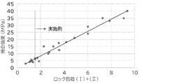
- the bond strength of the complex was measured and shown in FIG. As is clear from FIG. 5, it can be understood that the complex of the spiny liner having a lock index (I) + (II) of 1.55 or more and the outer peripheral member has excellent bonding strength.
Landscapes
- Engineering & Computer Science (AREA)
- Mechanical Engineering (AREA)
- Chemical & Material Sciences (AREA)
- Combustion & Propulsion (AREA)
- General Engineering & Computer Science (AREA)
- Cylinder Crankcases Of Internal Combustion Engines (AREA)
- Sliding-Contact Bearings (AREA)
- Pressure Welding/Diffusion-Bonding (AREA)
- Lining Or Joining Of Plastics Or The Like (AREA)
- Forging (AREA)
- Laminated Bodies (AREA)
- Pistons, Piston Rings, And Cylinders (AREA)
Abstract
Priority Applications (9)
| Application Number | Priority Date | Filing Date | Title |
|---|---|---|---|
| JP2021500764A JP6925559B1 (ja) | 2020-06-18 | 2020-06-18 | スパイニライナ及びその製造方法、並びに接合強度の鑑別法 |
| BR112021018697-2A BR112021018697B1 (pt) | 2020-06-18 | Forro espinhoso, método para fabricar o mesmo, e método para determinar a resistência de ligação | |
| PCT/JP2020/023956 WO2021255890A1 (fr) | 2020-06-18 | 2020-06-18 | Chemise striée, son procédé de fabrication, et procédé de discrimination de résistance d'assemblage |
| EP20923681.9A EP4170153A4 (fr) | 2020-06-18 | 2020-06-18 | Chemise striée, son procédé de fabrication, et procédé de discrimination de résistance d'assemblage |
| US17/439,433 US12305590B2 (en) | 2020-06-18 | 2020-06-18 | Spiny liner and manufacturing method of same, and method of determining bonding strength |
| MX2021011117A MX2021011117A (es) | 2020-06-18 | 2020-06-18 | Forro espinoso y metodo de fabricacion del mismo, y metodo de determinacion de la fuerza de adhesion. |
| KR1020217029019A KR102812058B1 (ko) | 2020-06-18 | 2020-06-18 | 스파이니 라이너 및 그 제조 방법, 그리고 접합 강도의 감별법 |
| CN202010815597.0A CN112096536B (zh) | 2020-06-18 | 2020-08-13 | 多棘衬套及其制造方法、以及接合强度的鉴别方法 |
| CN202021689393.9U CN212744165U (zh) | 2020-06-18 | 2020-08-13 | 多棘衬套 |
Applications Claiming Priority (1)
| Application Number | Priority Date | Filing Date | Title |
|---|---|---|---|
| PCT/JP2020/023956 WO2021255890A1 (fr) | 2020-06-18 | 2020-06-18 | Chemise striée, son procédé de fabrication, et procédé de discrimination de résistance d'assemblage |
Publications (1)
| Publication Number | Publication Date |
|---|---|
| WO2021255890A1 true WO2021255890A1 (fr) | 2021-12-23 |
Family
ID=73753729
Family Applications (1)
| Application Number | Title | Priority Date | Filing Date |
|---|---|---|---|
| PCT/JP2020/023956 Ceased WO2021255890A1 (fr) | 2020-06-18 | 2020-06-18 | Chemise striée, son procédé de fabrication, et procédé de discrimination de résistance d'assemblage |
Country Status (7)
| Country | Link |
|---|---|
| US (1) | US12305590B2 (fr) |
| EP (1) | EP4170153A4 (fr) |
| JP (1) | JP6925559B1 (fr) |
| KR (1) | KR102812058B1 (fr) |
| CN (2) | CN112096536B (fr) |
| MX (1) | MX2021011117A (fr) |
| WO (1) | WO2021255890A1 (fr) |
Families Citing this family (2)
| Publication number | Priority date | Publication date | Assignee | Title |
|---|---|---|---|---|
| MX2021011117A (es) * | 2020-06-18 | 2022-01-31 | Tpr Co Ltd | Forro espinoso y metodo de fabricacion del mismo, y metodo de determinacion de la fuerza de adhesion. |
| KR102622441B1 (ko) * | 2021-10-07 | 2024-01-08 | (주)원익머트리얼즈 | 황의 사용량에 따른 황화카보닐(cos)의 신규 합성방법 |
Citations (8)
| Publication number | Priority date | Publication date | Assignee | Title |
|---|---|---|---|---|
| JPH0210743B2 (fr) | 1980-10-06 | 1990-03-09 | Trw Repa Gmbh | |
| JP2003326353A (ja) * | 2002-05-13 | 2003-11-18 | Honda Motor Co Ltd | 鋳鉄製鋳ぐるみ部材 |
| JP2005194983A (ja) | 2004-01-09 | 2005-07-21 | Toyota Motor Corp | 鋳包み用シリンダライナ及びその製造方法 |
| JP2007016733A (ja) * | 2005-07-08 | 2007-01-25 | Toyota Motor Corp | シリンダライナ及びエンジン |
| JP2009264347A (ja) | 2008-04-30 | 2009-11-12 | Teikoku Piston Ring Co Ltd | 鋳包構造体 |
| JP2011194407A (ja) * | 2010-03-17 | 2011-10-06 | Moresco Corp | シリンダライナ及びその製造方法 |
| WO2019097573A1 (fr) * | 2017-11-14 | 2019-05-23 | 三菱電機株式会社 | Appareil à semi-conducteur et son procédé de fabrication |
| WO2019225038A1 (fr) * | 2018-05-24 | 2019-11-28 | Tpr株式会社 | Élément cylindrique |
Family Cites Families (4)
| Publication number | Priority date | Publication date | Assignee | Title |
|---|---|---|---|---|
| KR100650352B1 (ko) | 2002-05-13 | 2006-11-27 | 혼다 기켄 고교 가부시키가이샤 | 주철제 인서트 부재 및 그 제조 방법 |
| US10215128B2 (en) * | 2016-04-27 | 2019-02-26 | Mahle International Gmbh | Rough cast cylinder liner |
| WO2019097678A1 (fr) | 2017-11-17 | 2019-05-23 | Tpr株式会社 | Élément cylindrique en fonte et structure composite |
| MX2021011117A (es) | 2020-06-18 | 2022-01-31 | Tpr Co Ltd | Forro espinoso y metodo de fabricacion del mismo, y metodo de determinacion de la fuerza de adhesion. |
-
2020
- 2020-06-18 MX MX2021011117A patent/MX2021011117A/es unknown
- 2020-06-18 KR KR1020217029019A patent/KR102812058B1/ko active Active
- 2020-06-18 JP JP2021500764A patent/JP6925559B1/ja active Active
- 2020-06-18 EP EP20923681.9A patent/EP4170153A4/fr active Pending
- 2020-06-18 WO PCT/JP2020/023956 patent/WO2021255890A1/fr not_active Ceased
- 2020-06-18 US US17/439,433 patent/US12305590B2/en active Active
- 2020-08-13 CN CN202010815597.0A patent/CN112096536B/zh active Active
- 2020-08-13 CN CN202021689393.9U patent/CN212744165U/zh active Active
Patent Citations (8)
| Publication number | Priority date | Publication date | Assignee | Title |
|---|---|---|---|---|
| JPH0210743B2 (fr) | 1980-10-06 | 1990-03-09 | Trw Repa Gmbh | |
| JP2003326353A (ja) * | 2002-05-13 | 2003-11-18 | Honda Motor Co Ltd | 鋳鉄製鋳ぐるみ部材 |
| JP2005194983A (ja) | 2004-01-09 | 2005-07-21 | Toyota Motor Corp | 鋳包み用シリンダライナ及びその製造方法 |
| JP2007016733A (ja) * | 2005-07-08 | 2007-01-25 | Toyota Motor Corp | シリンダライナ及びエンジン |
| JP2009264347A (ja) | 2008-04-30 | 2009-11-12 | Teikoku Piston Ring Co Ltd | 鋳包構造体 |
| JP2011194407A (ja) * | 2010-03-17 | 2011-10-06 | Moresco Corp | シリンダライナ及びその製造方法 |
| WO2019097573A1 (fr) * | 2017-11-14 | 2019-05-23 | 三菱電機株式会社 | Appareil à semi-conducteur et son procédé de fabrication |
| WO2019225038A1 (fr) * | 2018-05-24 | 2019-11-28 | Tpr株式会社 | Élément cylindrique |
Non-Patent Citations (1)
| Title |
|---|
| See also references of EP4170153A4 |
Also Published As
| Publication number | Publication date |
|---|---|
| MX2021011117A (es) | 2022-01-31 |
| CN212744165U (zh) | 2021-03-19 |
| BR112021018697A2 (pt) | 2023-01-17 |
| CN112096536B (zh) | 2023-04-18 |
| JP6925559B1 (ja) | 2021-08-25 |
| CN112096536A (zh) | 2020-12-18 |
| JPWO2021255890A1 (fr) | 2021-12-23 |
| EP4170153A1 (fr) | 2023-04-26 |
| US12305590B2 (en) | 2025-05-20 |
| KR102812058B1 (ko) | 2025-05-23 |
| KR20230026928A (ko) | 2023-02-27 |
| EP4170153A4 (fr) | 2024-03-06 |
| US20220307443A1 (en) | 2022-09-29 |
Similar Documents
| Publication | Publication Date | Title |
|---|---|---|
| JP6510743B1 (ja) | 円筒部材 | |
| JP6925559B1 (ja) | スパイニライナ及びその製造方法、並びに接合強度の鑑別法 | |
| JP6340148B1 (ja) | 鋳鉄製円筒部材および複合構造体 | |
| US11141783B1 (en) | Cylinder liner for insert casting | |
| RU2808095C1 (ru) | Игольчатая гильза и способ ее изготовления, и способ определения прочности соединения | |
| CN113319266B (zh) | 缸套 | |
| BR112021018697B1 (pt) | Forro espinhoso, método para fabricar o mesmo, e método para determinar a resistência de ligação | |
| Muangjunburee et al. | Effect of Welding Speed and Tool Pin Profile on Weld Quality of Friction Stir Welded Semi-Solid Aluminium Alloy 356 |
Legal Events
| Date | Code | Title | Description |
|---|---|---|---|
| ENP | Entry into the national phase |
Ref document number: 2021500764 Country of ref document: JP Kind code of ref document: A |
|
| ENP | Entry into the national phase |
Ref document number: 20217029019 Country of ref document: KR Kind code of ref document: A |
|
| WWE | Wipo information: entry into national phase |
Ref document number: MX/A/2021/011117 Country of ref document: MX |
|
| REG | Reference to national code |
Ref country code: BR Ref legal event code: B01A Ref document number: 112021018697 Country of ref document: BR |
|
| 121 | Ep: the epo has been informed by wipo that ep was designated in this application |
Ref document number: 20923681 Country of ref document: EP Kind code of ref document: A1 |
|
| WWP | Wipo information: published in national office |
Ref document number: MX/A/2021/011117 Country of ref document: MX |
|
| ENP | Entry into the national phase |
Ref document number: 112021018697 Country of ref document: BR Kind code of ref document: A2 Effective date: 20210920 |
|
| WWE | Wipo information: entry into national phase |
Ref document number: 2021130031 Country of ref document: RU |
|
| NENP | Non-entry into the national phase |
Ref country code: DE |
|
| ENP | Entry into the national phase |
Ref document number: 2020923681 Country of ref document: EP Effective date: 20230118 |
|
| WWG | Wipo information: grant in national office |
Ref document number: 17439433 Country of ref document: US |
|
| WWG | Wipo information: grant in national office |
Ref document number: MX/A/2021/011117 Country of ref document: MX |