WO2021255893A1 - Electric heating device - Google Patents
Electric heating device Download PDFInfo
- Publication number
- WO2021255893A1 WO2021255893A1 PCT/JP2020/023962 JP2020023962W WO2021255893A1 WO 2021255893 A1 WO2021255893 A1 WO 2021255893A1 JP 2020023962 W JP2020023962 W JP 2020023962W WO 2021255893 A1 WO2021255893 A1 WO 2021255893A1
- Authority
- WO
- WIPO (PCT)
- Prior art keywords
- electric heating
- heating device
- heater
- ceramic insulator
- ceramic
- Prior art date
- Legal status (The legal status is an assumption and is not a legal conclusion. Google has not performed a legal analysis and makes no representation as to the accuracy of the status listed.)
- Ceased
Links
Images


Classifications
-
- H—ELECTRICITY
- H05—ELECTRIC TECHNIQUES NOT OTHERWISE PROVIDED FOR
- H05B—ELECTRIC HEATING; ELECTRIC LIGHT SOURCES NOT OTHERWISE PROVIDED FOR; CIRCUIT ARRANGEMENTS FOR ELECTRIC LIGHT SOURCES, IN GENERAL
- H05B3/00—Ohmic-resistance heating
- H05B3/62—Heating elements specially adapted for furnaces
- H05B3/64—Heating elements specially adapted for furnaces using ribbon, rod, or wire heater
-
- H—ELECTRICITY
- H05—ELECTRIC TECHNIQUES NOT OTHERWISE PROVIDED FOR
- H05B—ELECTRIC HEATING; ELECTRIC LIGHT SOURCES NOT OTHERWISE PROVIDED FOR; CIRCUIT ARRANGEMENTS FOR ELECTRIC LIGHT SOURCES, IN GENERAL
- H05B3/00—Ohmic-resistance heating
- H05B3/02—Details
- H05B3/06—Heater elements structurally combined with coupling elements or holders
-
- H—ELECTRICITY
- H05—ELECTRIC TECHNIQUES NOT OTHERWISE PROVIDED FOR
- H05B—ELECTRIC HEATING; ELECTRIC LIGHT SOURCES NOT OTHERWISE PROVIDED FOR; CIRCUIT ARRANGEMENTS FOR ELECTRIC LIGHT SOURCES, IN GENERAL
- H05B3/00—Ohmic-resistance heating
- H05B3/10—Heating elements characterised by the composition or nature of the materials or by the arrangement of the conductor
- H05B3/16—Heating elements characterised by the composition or nature of the materials or by the arrangement of the conductor the conductor being mounted on an insulating base
-
- H—ELECTRICITY
- H05—ELECTRIC TECHNIQUES NOT OTHERWISE PROVIDED FOR
- H05B—ELECTRIC HEATING; ELECTRIC LIGHT SOURCES NOT OTHERWISE PROVIDED FOR; CIRCUIT ARRANGEMENTS FOR ELECTRIC LIGHT SOURCES, IN GENERAL
- H05B3/00—Ohmic-resistance heating
- H05B3/40—Heating elements having the shape of rods or tubes
- H05B3/42—Heating elements having the shape of rods or tubes non-flexible
- H05B3/44—Heating elements having the shape of rods or tubes non-flexible heating conductor arranged within rods or tubes of insulating material
-
- H—ELECTRICITY
- H05—ELECTRIC TECHNIQUES NOT OTHERWISE PROVIDED FOR
- H05B—ELECTRIC HEATING; ELECTRIC LIGHT SOURCES NOT OTHERWISE PROVIDED FOR; CIRCUIT ARRANGEMENTS FOR ELECTRIC LIGHT SOURCES, IN GENERAL
- H05B3/00—Ohmic-resistance heating
- H05B3/40—Heating elements having the shape of rods or tubes
- H05B3/54—Heating elements having the shape of rods or tubes flexible
- H05B3/56—Heating cables
-
- Y—GENERAL TAGGING OF NEW TECHNOLOGICAL DEVELOPMENTS; GENERAL TAGGING OF CROSS-SECTIONAL TECHNOLOGIES SPANNING OVER SEVERAL SECTIONS OF THE IPC; TECHNICAL SUBJECTS COVERED BY FORMER USPC CROSS-REFERENCE ART COLLECTIONS [XRACs] AND DIGESTS
- Y02—TECHNOLOGIES OR APPLICATIONS FOR MITIGATION OR ADAPTATION AGAINST CLIMATE CHANGE
- Y02P—CLIMATE CHANGE MITIGATION TECHNOLOGIES IN THE PRODUCTION OR PROCESSING OF GOODS
- Y02P10/00—Technologies related to metal processing
- Y02P10/20—Recycling
Definitions
- the present invention relates to an electric heating device used in an industrial electric furnace, and particularly to a radiant tube heater in which a heat source is housed in a radiant tube.
- Patent Document 1 Japanese Patent No. 5270688
- the prior art is configured as follows. A radiant tube and a heating element arranged in the radiant tube are provided, and the heating element is composed of a heating wire and is connected to a current outlet at one end of the radiant tube. Further, the heating element is supported in the radiation tube with the support of the support. Then, a protective insert body made of a conductive material is arranged between the radiation tube and the heating element.
- a protective insert is placed between the radiation tube and the heating element so that the heating element residue and molten metal that can occur in the event of a device failure are with the help of gravity. Fall onto the protective insert. Therefore, it is said that it is possible to prevent unnecessary damage to the radiant tube and minimize the damage to the electric heating device due to the element failure.
- the above-mentioned prior art has the following problems. That is, in order to drop the heating element residue and molten metal that may occur in the event of an element failure onto the protective insert based on gravity, the above electric heating device must be horizontally mounted in the electric furnace. However, there is a problem that the arrangement structure of the electric heating device and its use are limited. Further, the above-mentioned conventional technique has a big problem that it does not prevent the element failure itself such as electric leakage from a heating element.
- the main object of the present invention is to provide an electric heating device capable of stable operation for a long period of time by reducing element failures that cause various troubles.
- the electric heating device is configured as follows. That is, the metal radiation tube 12, the plurality of heater wires 14 arranged so as to be parallel to each other in the radiation tube 12, and the surface thereof covered with an insulator on the central axis of the radiation tube 12 described above.
- a heater fixing shaft 16 arranged in the above and a disk-shaped ceramic insulator 18 attached to the heater fixing shaft 16 at predetermined intervals to support the heater wire 14 are provided.
- the ceramic porcelain 18 is formed with a central hole 20 through which the heater fixing shaft 16 is inserted and a heater wire holding hole 22 uniformly distributed on the circumference having the same center as the central hole 20.
- the outer diameter of the ceramic porcelain 18 itself or the diameter of its circumscribed circle as seen from the axial direction of the above-mentioned radiation tube 12 is larger than the inner diameter of the above-mentioned radiation tube 12 or the diameter of its inscribed circle. It is characterized in that it is formed so as to be small.
- the present inventors have described this type of electric heating device, that is, an electric heating device in which an insulator such as a heater fixing shaft or a ceramic porcelain and a heater wire are housed in a metal radiant tube to protect them from an external atmosphere. Due to the difference in the thermal expansion rate of each member during heat generation operation or stop cooling, the inner surface of the radiation tube and the peripheral edge of the (mainly) ceramic porcelain contact and slide, and the metal oxidation generated on the inner surface of the radiation tube. Objects will be scraped off and deposited around the heater wire on the ceramic porcelain. Then, as the amount of deposited metal oxide increases, a short circuit occurs between adjacent heater wires. We found that this was a major cause of element failure.
- the outer diameter of the ceramic porcelain 18 itself or the diameter of its circumscribed circle as seen from the axial direction of the radiant tube 12 is larger than the inner diameter of the radiant tube 12 or the diameter of its inscribed circle. Since it is formed so as to be small, the contact between the inner surface of the radiant tube 12 and the peripheral edge of the ceramic porcelain 18 at the time of heat generation operation or stop cooling of the electric heating device can be minimized, and the contact between the two can be minimized. The amount of scraped off metal oxide can be significantly reduced.
- the peripheral portion of the ceramic insulator 18 in contact with the radiation tube 12 is formed in an R shape. In this case, even if the inner surface of the radiation tube 12 and the peripheral edge of the ceramic insulator 18 come into contact with each other, the amount of metal oxide scraped off due to the contact between the two can be further reduced.
- the ceramic insulator 18 into a polygonal shape that is rotationally symmetric in a plan view.
- a gap can always be provided between the two, and the inner surface of the radiation tube 12 is scraped off through the gap. It is possible to reduce the amount of the metal oxide deposited on the ceramic insulator 18 by discharging the metal oxide downward.
- a concave groove 30 is formed at a position between the heater wire holding holes 22 adjacent to each other in the outer peripheral direction of the central hole 20 on the upper surface of the ceramic insulator 18. It is preferable to install it. In this case, the metal oxide that is scraped off from the inner surface of the radiation tube 12 or is released / dropped and deposited on the ceramic insulator 18 is accommodated in the groove 30. Therefore, it becomes possible to significantly delay the short circuit between the adjacent heater wires 14 due to the metal oxide.
- a substantially vertically steep step portion 32 by forming a wall thickness around the central hole 20 of the ceramic insulator 18.
- the metal oxide scraped off from the inner surface of the radiation tube 12 or released / dropped off is deposited above and below the stepped portion 32, and the adjacent heater wires 14 are connected to each other in the same manner as the above-mentioned concave groove 30. It will be possible to significantly delay the short circuit due to the metal oxide.
- the ceramic insulator 18 is lightened between the heater wire holding holes 22 adjacent to each other in the outer peripheral direction of the central hole 20 and adjacent to each other. It is preferable to dispose one of the heater wires 14 to be lightened. In this case, the adjacent heater wires 14 are supported by different ceramic insulators 18, and the short-circuiting of the adjacent heater wires 14 due to the metal oxide deposited on the ceramic insulator 18 is almost completely eliminated. You will be able to do it.
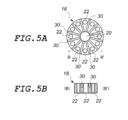
- FIG. 5A is a plan view showing a ceramic insulator of another embodiment (fourth embodiment) of the present invention.
- FIG. 5B is a cut end view of the BB'line in FIG. 5A.
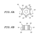
- FIG. 6A is a plan view showing a ceramic insulator of another embodiment (fifth embodiment) of the present invention.
- FIG. 6B is a cross-sectional view taken along the line DD'in FIG. 6A.
- FIG. 7A is a plan view showing an arrangement state of ceramic insulators of another embodiment (sixth embodiment) of the present invention.
- FIG. 7B is a cross-sectional view taken along the line EE'in FIG. 7A (partially omitted).
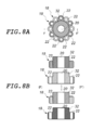
- FIG. 8A is a plan view showing an arrangement state of ceramic insulators of another embodiment (seventh embodiment) of the present invention.
- FIG. 8B is a cross-sectional view taken along the line FF'in FIG. 8A (partially omitted).
- FIG. 1 is a vertical cross-sectional view omitting a part of the internal structure (specifically, the heater wire 14 arranged on the front side) in the electric heating device 10 of the present embodiment.
- the electric heating device 10 of the present embodiment is a device used as a heat source for an industrial electric furnace used in various industrial processes, and as shown in this figure, a radiant tube 12, a heater wire 14, and a heater fixed shaft 16 It is roughly composed of a ceramic porcelain 18 and a ceramic porcelain 18.
- the radiation tube 12 is a metal tube in which a heating unit such as a heater wire 14 is housed by closing one end in the longitudinal direction and opening the other end in the longitudinal direction.
- the metal material constituting the radiant tube 12 is appropriately selected according to the usage environment of the electric heating device 10.
- a highly corrosion-resistant metal material such as Hastelloy (registered trademark of Haynes Co., Ltd .; the same applies hereinafter) C22. ..
- a pipe flange 24 is provided on the open end side of the other end in the longitudinal direction of the radiant pipe 12, and the electric heating device 10 can be used as a furnace wall (not shown) of an electric furnace via the pipe flange 24. Be attached to.
- the radiation tube 12 is formed of a cylindrical body is shown, but the form of the radiation tube 12 is not limited to this, and if necessary, for example, a polygonal cylinder or the like. May be.
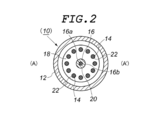
- the heater wire 14 is a long heating resistor made of a metal wire such as a nichrome wire or a Kanthal (registered trademark of Sandvik) wire, or a rod-shaped heating element such as SiC. By passing an electric current, the temperature rises to about 800 ° C to 1400 ° C depending on the type of material and the like. As shown in FIG. 2, in the present embodiment, twelve heater wires 14 are installed around the axis of the heater fixing shaft 16 described later at equal intervals, and the conductors are conductive such as Ni (nickel). They are electrically connected in series via a heater crossover plate (not shown) made of a material with excellent corrosion resistance. A plug 26 is attached to one end of the heater wire 14 in the longitudinal direction (lower end in the embodiment of FIG.
- the heater wire 14 is formed of a metal wire, the shape may be a straight single wire (rod shape) as shown in the illustrated embodiment, or the heater wire 14 may be a spirally wound metal wire. May be good.
- the heater fixing shaft 16 is a long member that supports the heater wire 14 via a ceramic insulator 18 described later, and functions as a core material 16a made of a stainless round bar and an insulator that covers the surface of the core material 16a. It is composed of a ceramic insulating cladding tube 16b.
- the heater fixing shaft 16 is arranged on the central axis of the radiation tube 12, and a plurality of ceramic insulators 18, which will be described later, are attached at predetermined intervals.
- the ceramic insulator 18 is a disk-shaped instrument that insulates and fixes the heater wire 14 at a predetermined position in the radiation tube 12 in cooperation with the heater fixing shaft 16.
- the ceramic insulator 18 is formed into a perfect circular shape in a plan view, and as shown in FIG. 1, the shape of the peripheral edge thereof is the center “C” in the thickness direction. Is the maximum outer diameter, and the outer diameter is gradually reduced toward both front and back sides. That is, the entire peripheral surface is formed in an R shape.
- a central hole 20 through which the heater fixing shaft 16 is inserted is inserted in the center thereof, and 12 heater wires are held evenly distributed on the circumference having the same center as the central hole 20.
- a hole 22 is formed.
- the outer diameter of the ceramic insulator 18 seen from the axial direction of the radiation tube 12 is set to be smaller than the inner diameter of the radiation tube 12, and the heater wire 14 is not operated at room temperature (normal temperature state). That is, in the normal state), the size is such that the two do not come into contact with each other.
- the entire peripheral surface of the porcelain 18 is formed in an R shape, the stress applied to the inner surface of the radiating tube 12 by the peripheral surface of the ceramic porcelain 18 when the inner surface of the radiation tube 12 and the peripheral edge of the ceramic porcelain 18 come into contact with each other. Can be alleviated and the amount of scraped off metal oxide can be significantly reduced. Therefore, the occurrence of element failure that causes various troubles can be delayed as much as possible, and stable operation for a long period of time becomes possible.
- the heater wire 14 and the heater fixing shaft 16 are in the shape of a round bar, but the shape of the heater wire 14 and the heater fixing shaft 16 is not limited to this.
- a square rod-shaped one may be used.
- the shape of the central hole 20 and the heater wire holding hole 22 of the ceramic insulator 18 is not a perfect circular shape, but a shape that follows the outer shape of the square rod-shaped heater wire 14 and the heater fixing shaft 16.
- the case where the radiation tube 12 is formed of a cylindrical body and the ceramic porcelain 18 is formed into a perfect circular shape in a plan view is shown.
- 18 may be formed into a polygonal shape in a plan view as described later.
- the ceramic insulator 18 may be formed into an elliptical shape in a plan view.
- the diameter of the circumscribed circle of the ceramic porcelain 18 seen from the axial direction of the radiation tube 12 is formed to be smaller than the diameter of the inscribed circle of the radiation tube 12. Will be done.
- FIG. 1 a case is shown in which the pipe flange 24 and the plug 26 are arranged under the radiation pipe 12 and the electric heating device 10 is erected in an electric furnace (not shown).
- the installation mode of the electric heating device 10 of the present invention in the electric furnace is not limited to this.
- the electric heating device 10 may be vertically installed in an electric furnace (not shown) by arranging it on the upper side.
- the plugs 26 may be provided at both ends in the longitudinal direction of the radiant tube 12 and the power may be supplied from both sides in the longitudinal direction of the radiant tube 12. Further, in the embodiment of FIG.
- the structure in which the tip (upper end) of the heater wire 14 reaches the ceiling surface of the radiation tube 12 is shown, but the tip end (upper end) of the heater wire 14 and the radiation tube 12 are shown. It may have a structure in which a space is provided between the ceiling surface and the ceiling surface. The same applies to this point when the top and bottom of the electric heating device 10 are reversed as described above.
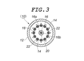
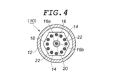
- the ceramic porcelain 18 is formed in a perfect circular shape in a plan view, but the ceramic porcelain 18 is, for example, rotationally symmetric in a plan view as shown in FIG. It is more preferable to have a polygonal shape that is rotationally symmetric in a plane view, such as an object formed in a star-shaped polygonal shape or an object having a regular hexagonal shape in a plan view as shown in FIG. Further, as described above, the ceramic insulator 18 may be formed into an elliptical shape in a plan view. However, even in these cases, it is preferable that the shape of the peripheral edge of the ceramic insulator 18 is an R shape in the entire peripheral surface or a part in contact with the inner surface of the radiation tube 12.
- the surface (upper surface) of the ceramic insulator 18 is formed on a plane, but for example, as shown in FIG. 5, they are adjacent to each other in the outer peripheral direction of the central hole 20 on the upper surface of the ceramic insulator 18. It is preferable to dig a concave groove 30 at a position between the heater wire holding holes 22.
- the generation of metal oxides due to rubbing between the ceramic porcelain 18 and the inner surface of the radiation tube 12 can be dealt with by the above-mentioned technique, but in addition to rubbing, powder caused by oxidation of the metal surface due to high temperature is generated, and this metal is generated. Oxide powder may be released / dropped from the surface of the radiation tube 12 and deposited on the surface of the ceramic porcelain 18.
- the adjacent heater wires 14 are short-circuited by the metal oxide deposited on the ceramic insulator 18, which causes an electric leakage.
- the adjacent heaters are formed. It is possible to significantly delay the short circuit between the wires 14 due to the metal oxide powder.
- each of the ceramic insulators 18 holds all of the plurality (12) heater wires 14 arranged so as to be parallel to each other by the heater wire holding holes 22.
- the space between the heater wire holding holes 22 adjacent to each other in the outer peripheral direction of the central hole 20 of the ceramic insulator 18 is cut out, and the adjacent heater wires are used.
- one of 14 is arranged in the lightening portion. With this configuration, the adjacent heater wires 14 are supported by different ceramic insulators 18, and the metal oxides deposited on the ceramic insulators 18 cause the adjacent heater wires 14 to be almost completely short-circuited. You will be able to eliminate it.
- a rotationally symmetric ceramic insulator 18 provided with six heater wire holding holes 22 is used, and the ceramic insulator 18 is rotated by 30 ° up and down and arranged. , 12 heater wires 14 are held, but in this embodiment, the gaps between the heater wire holding holes 22 adjacent to each other in the outer peripheral direction of the central hole 20 of the ceramic insulator 18 are lightened and adjacent to each other. Any aspect may be used as long as one of the heater wires 14 is arranged in the lightening portion thereof, and the present invention is not limited to the one shown in the above illustration.
Landscapes
- Resistance Heating (AREA)
Abstract
Description
本発明は、産業用電気炉で使用される電熱装置に関し、とりわけ熱源が放射管内に収容されたラジアントチューブヒータに関する。 The present invention relates to an electric heating device used in an industrial electric furnace, and particularly to a radiant tube heater in which a heat source is housed in a radiant tube.
この種の電熱装置には、従来では、下記の特許文献1(日本国・特許第5270688号公報)に記載されたものがある。その従来技術は、次のように構成されている。
放射管と、その放射管内に配置される発熱体とを備え、前記発熱体は、電熱線で構成されると共に、前記放射管の一端で電流取出口に接続される。また、前記発熱体は、支持体の支援を受けて前記放射管内に支持される。そして、前記放射管と前記発熱体との間には導電材料の保護挿入体が配置される。
Conventionally, there is an electric heating device of this type described in Patent Document 1 (Japanese Patent No. 5270688) described below. The prior art is configured as follows.
A radiant tube and a heating element arranged in the radiant tube are provided, and the heating element is composed of a heating wire and is connected to a current outlet at one end of the radiant tube. Further, the heating element is supported in the radiation tube with the support of the support. Then, a protective insert body made of a conductive material is arranged between the radiation tube and the heating element.
上記の従来技術によれば、放射管と発熱体との間に保護挿入体が配置されているので、素子故障の際に起こり得る発熱体残留物と溶融した金属とが重力の助けを借りて保護挿入体上に落下する。このため、放射管の無用な損傷を防止して、素子故障によって電熱装置が受ける被害を最小限に抑えることができる、とされている。 According to the above prior art, a protective insert is placed between the radiation tube and the heating element so that the heating element residue and molten metal that can occur in the event of a device failure are with the help of gravity. Fall onto the protective insert. Therefore, it is said that it is possible to prevent unnecessary damage to the radiant tube and minimize the damage to the electric heating device due to the element failure.
しかしながら、上記の従来技術には次の課題がある。
すなわち、素子故障の際に起こり得る発熱体残留物や溶融した金属を重力に基づいて保護挿入体の上に落下させるためには、電気炉内において、上記の電熱装置を水平実装しなければならず、電熱装置の配設構造やその用途が限られるという問題があった。
また、上記の従来技術は、発熱体からの漏電などと言った素子故障それ自体を予防するものではないという大きな問題がある。
However, the above-mentioned prior art has the following problems.
That is, in order to drop the heating element residue and molten metal that may occur in the event of an element failure onto the protective insert based on gravity, the above electric heating device must be horizontally mounted in the electric furnace. However, there is a problem that the arrangement structure of the electric heating device and its use are limited.
Further, the above-mentioned conventional technique has a big problem that it does not prevent the element failure itself such as electric leakage from a heating element.
それゆえに、本発明の主たる目的は、様々なトラブルの原因となる素子故障を低減させることによって、長期間の安定した稼働が可能な電熱装置を提供することである。 Therefore, the main object of the present invention is to provide an electric heating device capable of stable operation for a long period of time by reducing element failures that cause various troubles.
上記目的を達成するため、本発明は、図1~図2に示すように、電熱装置を次のように構成した。
すなわち、金属製の放射管12と、その放射管12内にて互いに平行するように配置される複数本のヒータ線14と、表面が絶縁体で被覆され、上記の放射管12の中心軸線上に配設されるヒータ固定軸16と、そのヒータ固定軸16に所定の間隔で取り付けられて上記ヒータ線14を支持するディスク状のセラミック碍子18とを備える。そして、上記セラミック碍子18は、その中心に上記ヒータ固定軸16が挿通される中央孔20及びその中央孔20と同じ中心を持つ円周上に均等に分布されたヒータ線保持孔22が穿設されると共に、常態において、上記の放射管12の軸方向から見た当該セラミック碍子18それ自身の外径もしくはその外接円の直径が、上記の放射管12の内径もしくはその内接円の直径よりも小さくなるように形成されることを特徴とする。
In order to achieve the above object, in the present invention, as shown in FIGS. 1 and 2, the electric heating device is configured as follows.
That is, the
本発明者らは、この種の電熱装置、すなわち、ヒータ固定軸やセラミック碍子などの絶縁体とヒータ線とを金属製の放射管に収容して外部雰囲気から保護する電熱装置において、当該電熱装置の発熱作動時または停止冷却時に、各部材の熱膨張率の違いから、放射管の内面と、(主として)セラミック碍子の周縁とが接触・摺動し、放射管の内面に生成される金属酸化物が削り落とされてセラミック碍子上のヒータ線周りに堆積するようになる。そして、堆積した金属酸化物の量が増えると、隣接するヒータ線の間を短絡するようになる。これが素子故障の大きな原因であることを突きとめた。
そこで、本発明の電熱装置では、常態において、放射管12の軸方向から見たセラミック碍子18それ自身の外径もしくはその外接円の直径が、放射管12の内径もしくはその内接円の直径よりも小さくなるように形成されるので、当該電熱装置の発熱作動時または停止冷却時における放射管12の内面とセラミック碍子18の周縁部との接触を極小化することができ、両者の接触に伴う金属酸化物の削り落とし量を著しく低減させることができる。
The present inventors have described this type of electric heating device, that is, an electric heating device in which an insulator such as a heater fixing shaft or a ceramic porcelain and a heater wire are housed in a metal radiant tube to protect them from an external atmosphere. Due to the difference in the thermal expansion rate of each member during heat generation operation or stop cooling, the inner surface of the radiation tube and the peripheral edge of the (mainly) ceramic porcelain contact and slide, and the metal oxidation generated on the inner surface of the radiation tube. Objects will be scraped off and deposited around the heater wire on the ceramic porcelain. Then, as the amount of deposited metal oxide increases, a short circuit occurs between adjacent heater wires. We found that this was a major cause of element failure.
Therefore, in the electric heating device of the present invention, under normal conditions, the outer diameter of the
本発明において、前記セラミック碍子18は、その周縁部のうち少なくとも前記の放射管12と接触する部分がR形状にて形成されるのが好ましい。
この場合、仮に放射管12の内面とセラミック碍子18の周縁部とが接触した場合であっても、両者の接触に伴う金属酸化物の削り落とし量をより一層低減させることができる。
In the present invention, it is preferable that at least a portion of the peripheral portion of the
In this case, even if the inner surface of the
また、本発明においては、図3及び図4に示すように、前記セラミック碍子18を、平面視で回転対称な多角形状に形成するのが好ましい。
この場合、放射管12の内面とセラミック碍子18の周縁部とが接触した場合であっても、両者の間に常に隙間を設けることができ、当該隙間を介して放射管12の内面から削り落とされた金属酸化物を下方へと排出させてセラミック碍子18上に堆積するのを低減させることができる。
Further, in the present invention, as shown in FIGS. 3 and 4, it is preferable to form the
In this case, even when the inner surface of the
また、本発明では、図5に示すように、前記セラミック碍子18の上面における前記の中央孔20の外周方向にて互いに隣接する前記ヒータ線保持孔22の間の位置に、凹溝30を堀設するのが好ましい。
この場合、放射管12の内面から削り落とされたり遊離・脱落してセラミック碍子18上に堆積する金属酸化物が当該凹溝30内に収容されるようになる。このため、隣接するヒータ線14同士がその金属酸化物によって短絡するのを著しく遅延させることができるようになる。
Further, in the present invention, as shown in FIG. 5, a
In this case, the metal oxide that is scraped off from the inner surface of the
さらに、本発明においては、図6に示すように、前記セラミック碍子18の中央孔20周りを肉厚に形成することによって、略垂直に切り立った段部32を形成するのが好ましい。
この場合、放射管12の内面から削り落とされたり遊離・脱落した金属酸化物が段部32の上下に堆積するようになり、上述した凹溝30と同様に、隣接するヒータ線14同士がその金属酸化物によって短絡するのを著しく遅延させることができるようになる。
Further, in the present invention, as shown in FIG. 6, it is preferable to form a substantially vertically
In this case, the metal oxide scraped off from the inner surface of the
そして、本発明では、図7および図8に示すように、前記セラミック碍子18は、前記の中央孔20の外周方向にて互いに隣接する前記ヒータ線保持孔22の間を肉抜きすると共に、隣接する前記ヒータ線14のうち一方をその肉抜き部分に配設するのが好ましい。
この場合、隣接するヒータ線14は、それぞれ別のセラミック碍子18で支持されるようになり、セラミック碍子18上に堆積する金属酸化物によって隣接するヒータ線14同士が短絡するのをほぼ完全に無くすことができるようになる。
Then, in the present invention, as shown in FIGS. 7 and 8, the
In this case, the
以下、本発明の一実施形態について、図1および図2を参照しながら説明する。
図1は、本実施形態の電熱装置10における内部構造の一部(具体的には正面側に配置されるヒータ線14など)を省略した垂直断面図である。本実施形態の電熱装置10は、様々な工業プロセスで使用される産業用電気炉の熱源として使用される装置であり、この図が示すように、放射管12,ヒータ線14,ヒータ固定軸16およびセラミック碍子18で大略構成される。
Hereinafter, an embodiment of the present invention will be described with reference to FIGS. 1 and 2.
FIG. 1 is a vertical cross-sectional view omitting a part of the internal structure (specifically, the
放射管12は、長手方向一端が閉塞され、長手方向他端が開放されることによって、その内部にヒータ線14などの発熱ユニットが収納される金属製の管体である。この放射管12は、上記の発熱ユニットを外部雰囲気(=炉内環境)から保護すると共に、ヒータ線14が発した熱を外部(炉内)へと放射させるためのものである。
The
放射管12を構成する金属材料は、電熱装置10の使用環境に応じて適宜選択される。例えば、この放射管12の外部環境が腐食性の強いガスが存在する場合には、ハステロイ(ヘインズ社登録商標;以下同じ)C22などのように、高耐食性の金属材料を用いるのが好適である。
The metal material constituting the
また、この放射管12の長手方向他端の開放端側には、管フランジ24が設けられており、この管フランジ24を介して、電熱装置10が電気炉の炉壁(図示せず)などに取着される。
なお、図示実施形態では、この放射管12を円筒体で構成する場合を示しているが、放射管12の形態はこれに限定されるものではなく、必要に応じて、例えば、多角筒体などであってもよい。
Further, a
In the illustrated embodiment, the case where the
ヒータ線14は、ニクロム線やカンタル(サンドビック社登録商標)線などの金属線のほかに、例えばSiCなどの発熱体を棒状に成形したもの等からなる長尺の発熱抵抗体であって、電流を流すことにより材料の種類等に応じて概ね800℃~1400℃程度まで昇温する。図2に示すように、本実施形態では、このヒータ線14が、後述するヒータ固定軸16の軸周りに互いに等しい間隔をあけて12本設置されると共に、Ni(ニッケル)などの導電性と耐食性とに優れた材料で形成されたヒータ渡りプレート(図示せず)を介して電気的に直列にて接続される。そして、このヒータ線14の長手方向一端(図1の実施形態では下端)にプラグ26が取り付けられ、このプラグ26の端子26aに図示しない電源からの配線が接続される。
なお、このヒータ線14を金属線で形成する場合、その形状は、図示実施形態のようにストレートな単線(棒状)であってもよいし、金属線を螺旋状に巻回した物であってもよい。
The
When the
ヒータ固定軸16は、後述するセラミック碍子18を介してヒータ線14を支持する長尺部材で、ステンレス丸棒材からなる芯材16aと、その芯材16aの表面を被覆する絶縁体として機能するセラミック製の絶縁被覆管16bとで構成される。
このヒータ固定軸16は、放射管12の中心軸線上に配設されると共に、所定の間隔をあけて後述する複数のセラミック碍子18が取り付けられる。
The
The
セラミック碍子18は、ヒータ固定軸16と協働して放射管12内の所定位置でヒータ線14を絶縁固定するディスク状の器具である。本実施形態では、図2に示すように、このセラミック碍子18が、平面視で真円形状に形成されると共に、図1に示すように、その周縁の形状が、厚さ方向中央 “C”が最大外径となり、表裏両面側へ向かうに従ってその外径が漸次縮径するように形成される。つまり、周面全体がR形状にて形成されている。
The
また、このセラミック碍子18には、その中心に上記ヒータ固定軸16が挿通される中央孔20と、その中央孔20と同じ中心を持つ円周上に均等に分布された12個のヒータ線保持孔22とが穿設されている。
そして特筆すべきは、このセラミック碍子18は、放射管12の軸方向から見たその外径が、放射管12の内径よりも小さく設定されており、ヒータ線14を作動させていない常温状態(すなわち、常態)において、両者が接触しない大きさとなっている。
Further, in the
It should be noted that the outer diameter of the
以上のように構成された本実施形態の電熱装置10によれば、ヒータ線14に通電して発熱させる際やヒータ線14への通電を停止して冷却させる際に、各部材の熱膨張率に違いが有ったとしても、放射管12の内面とセラミック碍子18の周縁とが接触・摺動するのを防止して放射管12の内面に生成される金属酸化物が削り落とされるのを抑制することができる。また、仮に放射管12の内面と(主として)セラミック碍子18の周縁とが接触・摺動して放射管12の内面に生成される金属酸化物が削り落とされるような場合であっても、セラミック碍子18の周面全体がR形状にて形成されるので、放射管12の内面とセラミック碍子18の周縁部とが接触した際に、セラミック碍子18の周縁部が放射管12の内面に与える応力を緩和して金属酸化物の削り落とし量を著しく低減させることができる。このため、様々なトラブルの原因となる素子故障の発生を最大限遅延させることができ、長期間の安定した稼働が可能となる。
According to the
なお、上述の実施形態では、ヒータ線14やヒータ固定軸16として、丸棒状のものを用いる場合を示しているが、ヒータ線14やヒータ固定軸16の形状はこれに限定されるものではなく、例えば角棒状のものを用いるようにしてもよい。但し、その場合、セラミック碍子18の中央孔20やヒータ線保持孔22の形状も真円形状ではなく、角棒状のヒータ線14やヒータ固定軸16の外形に沿った形状のものとなる。
In the above embodiment, the
上述の実施形態では、放射管12内において、ヒータ固定軸16に対して6個のセラミック碍子18が装着される場合を示しているが、このヒータ固定軸16に装着させるセラミック碍子18の数はこれに限定されるものではなく、例えば、5個以下であってもよいし、7個以上であってもよい。但し、ヒータ線14の発熱による熱量を吸収し当該電熱装置10の熱効率を阻害することの無いよう個数については配慮する必要がある。
In the above-described embodiment, the case where six
上述の実施形態では、放射管12内に12本のヒータ線14を配設する場合を示しているが(図2参照)、放射管12内に配設するヒータ線14の本数はこれに限定されるものではなく、必要に応じて適宜増減することができる。
In the above embodiment, the case where 12
上述の実施形態では、放射管12を円筒体で構成すると共に、セラミック碍子18を平面視で真円形状に形成する場合を示したが、放射管12を多角筒体で構成すると共に、セラミック碍子18を後述するように平面視で多角形状に形成するようにしてもよい。又、セラミック碍子18を平面視で楕円形状に形成するようにしてもよい。尤も、これらのような場合であっても、常態において、放射管12の軸方向から見たセラミック碍子18の外接円の直径が、放射管12の内接円の直径よりも小さくなるように形成される。
In the above-described embodiment, the case where the
上述の実施形態では、図1に示すように、管フランジ24やプラグ26を放射管12の下側に配置して、図示しない電気炉内で電熱装置10が立設される場合を示しているが、電気炉内における本発明の電熱装置10の設置態様はこれに限定されるものではなく、例えば、管フランジ24やプラグ26を、図1のものとは天地を逆にした放射管12の上側に配置して、図示しない電気炉内で電熱装置10を垂設するようにしてもよい。また、電熱装置10への給電はプラグ26を介して行われるが、このプラグ26を放射管12の長手方向両端に設け、放射管12の長手方向両側から給電するようにしてもよい。更に、図1の実施形態では、ヒータ線14の先端(上端)が放射管12の天井面に達している構造のものを示しているが、このヒータ線14の先端(上端)と放射管12の天井面との間にスペースが設けられる構造のものであってもよい。この点については、上述のように電熱装置10の天地が逆となる場合も同様である。
In the above-described embodiment, as shown in FIG. 1, a case is shown in which the
また、上述の実施形態では、セラミック碍子18として、平面視で真円形状に形成されたものを用いているが、このセラミック碍子18は、例えば、図3に示すような平面視で回転対称な星形多角形状に形成した物や、図4に示すような平面視で正六角形状の物などのように、平面視で回転対称な多角形状とするのがより好ましい。又、上述したようにセラミック碍子18を平面視で楕円形状に形成するようにしてもよい。尤も、これらのような場合であっても、セラミック碍子18の周縁の形状は、周面全体又は放射管12の内面と接触する一部がR形状にて形成されていることが好ましい。
係る構成により、ヒータ線14の発熱によって放射管12の内面とセラミック碍子18の周縁部とが接触した場合であっても、両者の間に隙間を設けることができ、当該隙間を介して放射管12の内面から削り落とされた金属酸化物を下方へと排出させてセラミック碍子18上に堆積するのをより一層低減させることができるようになる。
Further, in the above-described embodiment, the
With this configuration, even when the inner surface of the
また、上述の実施形態では、セラミック碍子18の表面(上面)をプレーンに形成しているが、例えば、図5に示すように、セラミック碍子18の上面における中央孔20の外周方向にて互いに隣接するヒータ線保持孔22の間の位置に、凹溝30を堀設するのが好ましい。
セラミック碍子18と放射管12の内面との擦れによる金属酸化物の発生は上述してきた技術により対応できるが、擦れ以外にも高温による金属表面の酸化を要因とする粉体が発生し、この金属酸化物の粉体が放射管12表面から遊離・脱落してセラミック碍子18表面上に堆積する場合がある。このような場合にも、セラミック碍子18に堆積した金属酸化物によって隣接するヒータ線14同士が短絡し、漏電の原因となる。
しかしながら、この実施形態のように、セラミック碍子18の上面における中央孔20の外周方向にて互いに隣接するヒータ線保持孔22の間の位置に、凹溝30を堀設することによって、隣接するヒータ線14同士がその金属酸化物粉体によって短絡するのを著しく遅延させることができる。
Further, in the above-described embodiment, the surface (upper surface) of the
The generation of metal oxides due to rubbing between the
However, as in this embodiment, by digging a
さらに、上記の凹溝30に替えて、或いは、上記の凹溝30と共に、図6に示すように、セラミック碍子18の中央孔20周りを肉厚に形成することによって、略垂直に切り立った段部32を形成するのが好ましい。この場合、略垂直に切り立った立ち上がり面には金属粉体が堆積しないことから、放射管12の内面から削り落とされたり遊離・脱落した金属酸化物が段部32の上下に堆積したとしても、上述した凹溝30と同様に、隣接するヒータ線14同士がその金属酸化物によって短絡するのを著しく遅延させることができる。
Further, instead of the above-mentioned
そして、図1に示された上述の実施形態では、各セラミック碍子18のそれぞれが、互いに平行するように配置される複数本(12本)のヒータ線14の全てをヒータ線保持孔22で保持する場合を示したが、例えば、図7や図8に示すように、セラミック碍子18の中央孔20外周方向にて互いに隣接するヒータ線保持孔22の間を肉抜きすると共に、隣接するヒータ線14のうち一方をその肉抜き部分に配設するようにするのが好ましい。係る構成により、隣接するヒータ線14は、それぞれ別のセラミック碍子18で支持されるようになり、セラミック碍子18上に堆積する金属酸化物によって隣接するヒータ線14同士が短絡するのをほぼ完全に無くすことができるようになる。
Then, in the above-described embodiment shown in FIG. 1, each of the
なお、図7及び図8に示す例では、6つのヒータ線保持孔22が設けられた回転対称形のセラミック碍子18を用い、このセラミック碍子18を上下で30°ずつ回転させて配置することによって、12本のヒータ線14を保持する場合を示しているが、この実施形態は、セラミック碍子18の中央孔20外周方向にて互いに隣接するヒータ線保持孔22の間を肉抜きすると共に、隣接するヒータ線14のうち一方をその肉抜き部分に配設する態様であれば如何なるものであってもよく、上記図示のものに限定されるものではない。
In the examples shown in FIGS. 7 and 8, a rotationally symmetric
その他に、本発明は、当業者が想定できる範囲で種々の変更を行えることは勿論である。 In addition, it goes without saying that the present invention can be modified in various ways within the range that can be assumed by those skilled in the art.
10:電熱装置,12:放射管,14:ヒータ線,16:ヒータ固定軸,18:セラミック碍子,20:中央孔,22:ヒータ線保持孔,30:凹溝,32:段部. 10: Electric heating device, 12: Radiant tube, 14: Heater wire, 16: Heater fixing shaft, 18: Ceramic insulator, 20: Central hole, 22: Heater wire holding hole, 30: Recessed groove, 32: Step part.
Claims (6)
上記セラミック碍子(18)は、その中心に上記ヒータ固定軸(16)が挿通される中央孔(20)及びその中央孔(20)と同じ中心を持つ円周上に均等に分布されたヒータ線保持孔(22)が穿設されると共に、常態において、上記の放射管(12)の軸方向から見た当該セラミック碍子(18)それ自身の外径もしくはその外接円の直径が、上記の放射管(12)の内径もしくはその内接円の直径よりも小さくなるように形成される、
ことを特徴とする電熱装置。 A metal radiant tube (12), a plurality of heater wires (14) arranged parallel to each other in the radiant tube (12), and the above-mentioned radiant tube (14) whose surface is covered with an insulator. A disk-shaped ceramic insulator (18) arranged on the central axis of 12) and attached to the heater fixing shaft (16) at a predetermined interval to support the heater wire (14). ) And an electric heating device,
The ceramic porcelain (18) has a central hole (20) through which the heater fixing shaft (16) is inserted in the center thereof and a heater wire uniformly distributed on the circumference having the same center as the central hole (20). The holding hole (22) is bored, and under normal conditions, the outer diameter of the ceramic porcelain (18) itself or the diameter of its circumscribed circle as seen from the axial direction of the radiation tube (12) is the above radiation. It is formed so as to be smaller than the inner diameter of the tube (12) or the diameter of its inscribed circle.
An electric heating device characterized by that.
前記セラミック碍子(18)は、その周縁部のうち少なくとも前記の放射管(12)と接触する部分がR形状にて形成される、ことを特徴とする電熱装置。 In the electric heating device of claim 1,
The ceramic insulator (18) is an electric heating device characterized in that at least a portion of the peripheral portion thereof in contact with the radiant tube (12) is formed in an R shape.
前記セラミック碍子(18)が、平面視で回転対称な多角形状に形成される、ことを特徴とする電熱装置。 In the electric heating device according to claim 1 or 2.
An electric heating device characterized in that the ceramic insulator (18) is formed into a polygonal shape that is rotationally symmetric in a plan view.
前記セラミック碍子(18)の上面には、前記の中央孔(20)の外周方向にて互いに隣接する前記ヒータ線保持孔(22)の間の位置に凹溝(30)が堀設される、ことを特徴とする電熱装置。 In the electric heating device according to any one of claims 1 to 3.
A concave groove (30) is formed on the upper surface of the ceramic insulator (18) at a position between the heater wire holding holes (22) adjacent to each other in the outer peripheral direction of the central hole (20). An electric heating device characterized by that.
前記セラミック碍子(18)は、前記の中央孔(20)周りが肉厚に形成されて、略垂直に切り立った段部(32)が形成される、ことを特徴とする電熱装置。 In the electric heating device according to any one of claims 1 to 3.
The ceramic insulator (18) is an electric heating device characterized in that the circumference of the central hole (20) is formed to be thick, and a step portion (32) is formed so as to be substantially vertically steep.
前記セラミック碍子(18)は、前記の中央孔(20)の外周方向にて互いに隣接する前記ヒータ線保持孔(22)の間が肉抜きされると共に、隣接する前記ヒータ線(14)のうち一方がその肉抜き部分に配設される、ことを特徴とする電熱装置。
In the electric heating device according to any one of claims 1 to 3.
The ceramic insulator (18) is lightened between the heater wire holding holes (22) adjacent to each other in the outer peripheral direction of the central hole (20), and among the adjacent heater wires (14). An electric heating device characterized in that one is arranged in the lightening portion.
Priority Applications (5)
| Application Number | Priority Date | Filing Date | Title |
|---|---|---|---|
| US18/000,890 US20240237155A1 (en) | 2020-06-18 | 2020-06-18 | Electric heating device |
| JP2022531198A JP7161816B2 (en) | 2020-06-18 | 2020-06-18 | electric heating device |
| PCT/JP2020/023962 WO2021255893A1 (en) | 2020-06-18 | 2020-06-18 | Electric heating device |
| KR1020227041882A KR20230003190A (en) | 2020-06-18 | 2020-06-18 | electrothermal device |
| CN202080100953.9A CN115669218A (en) | 2020-06-18 | 2020-06-18 | Electric heating device |
Applications Claiming Priority (1)
| Application Number | Priority Date | Filing Date | Title |
|---|---|---|---|
| PCT/JP2020/023962 WO2021255893A1 (en) | 2020-06-18 | 2020-06-18 | Electric heating device |
Publications (1)
| Publication Number | Publication Date |
|---|---|
| WO2021255893A1 true WO2021255893A1 (en) | 2021-12-23 |
Family
ID=79267657
Family Applications (1)
| Application Number | Title | Priority Date | Filing Date |
|---|---|---|---|
| PCT/JP2020/023962 Ceased WO2021255893A1 (en) | 2020-06-18 | 2020-06-18 | Electric heating device |
Country Status (5)
| Country | Link |
|---|---|
| US (1) | US20240237155A1 (en) |
| JP (1) | JP7161816B2 (en) |
| KR (1) | KR20230003190A (en) |
| CN (1) | CN115669218A (en) |
| WO (1) | WO2021255893A1 (en) |
Cited By (1)
| Publication number | Priority date | Publication date | Assignee | Title |
|---|---|---|---|---|
| JP7140440B1 (en) * | 2022-01-28 | 2022-09-21 | カンケンテクノ株式会社 | Tubular heating unit and exhaust gas treatment device provided with the tubular heating unit |
Families Citing this family (1)
| Publication number | Priority date | Publication date | Assignee | Title |
|---|---|---|---|---|
| JP7325151B1 (en) | 2023-04-10 | 2023-08-14 | カンケンテクノ株式会社 | Tubular heating unit and exhaust gas treatment device provided with the tubular heating unit |
Citations (6)
| Publication number | Priority date | Publication date | Assignee | Title |
|---|---|---|---|---|
| JPS5926895U (en) * | 1982-08-13 | 1984-02-20 | ミクニ機工株式会社 | Support insulator for tube heater |
| JPS61142685A (en) * | 1984-12-14 | 1986-06-30 | ニムラ鋼機株式会社 | Radiatnt tube type heater |
| JPH02143795U (en) * | 1989-05-02 | 1990-12-06 | ||
| JPH07312278A (en) * | 1993-04-02 | 1995-11-28 | Kanthal Gmbh | Ceramic disk for exothermic resistor support in heating element of electric furnace for industry |
| JP2011029028A (en) * | 2009-07-27 | 2011-02-10 | Mikuni Kiko Kk | Insulator for heater in furnace, and heater in furnace employing the same |
| JP5270688B2 (en) * | 2007-12-10 | 2013-08-21 | サンドビック インテレクチュアル プロパティー アクティエボラーグ | Electric heating device |
Family Cites Families (5)
| Publication number | Priority date | Publication date | Assignee | Title |
|---|---|---|---|---|
| US2888546A (en) * | 1957-09-16 | 1959-05-26 | Theodore S Kinney | Immersion electric heater |
| US4322606A (en) * | 1980-04-28 | 1982-03-30 | Agf Inc. | Electrical heating element assembly |
| DE3445489C2 (en) * | 1984-12-13 | 1986-11-20 | Messerschmitt-Bölkow-Blohm GmbH, 8012 Ottobrunn | Device for fastening several electrical lines in an aircraft |
| SE526522C2 (en) * | 2003-06-27 | 2005-10-04 | Sandvik Intellectual Property | Ceramic support plate for heat conductors |
| DE202008016439U1 (en) * | 2008-12-11 | 2009-03-12 | Türk & Hillinger GmbH | Cartridge Heater |
-
2020
- 2020-06-18 KR KR1020227041882A patent/KR20230003190A/en active Pending
- 2020-06-18 JP JP2022531198A patent/JP7161816B2/en active Active
- 2020-06-18 US US18/000,890 patent/US20240237155A1/en active Pending
- 2020-06-18 WO PCT/JP2020/023962 patent/WO2021255893A1/en not_active Ceased
- 2020-06-18 CN CN202080100953.9A patent/CN115669218A/en active Pending
Patent Citations (6)
| Publication number | Priority date | Publication date | Assignee | Title |
|---|---|---|---|---|
| JPS5926895U (en) * | 1982-08-13 | 1984-02-20 | ミクニ機工株式会社 | Support insulator for tube heater |
| JPS61142685A (en) * | 1984-12-14 | 1986-06-30 | ニムラ鋼機株式会社 | Radiatnt tube type heater |
| JPH02143795U (en) * | 1989-05-02 | 1990-12-06 | ||
| JPH07312278A (en) * | 1993-04-02 | 1995-11-28 | Kanthal Gmbh | Ceramic disk for exothermic resistor support in heating element of electric furnace for industry |
| JP5270688B2 (en) * | 2007-12-10 | 2013-08-21 | サンドビック インテレクチュアル プロパティー アクティエボラーグ | Electric heating device |
| JP2011029028A (en) * | 2009-07-27 | 2011-02-10 | Mikuni Kiko Kk | Insulator for heater in furnace, and heater in furnace employing the same |
Cited By (5)
| Publication number | Priority date | Publication date | Assignee | Title |
|---|---|---|---|---|
| JP7140440B1 (en) * | 2022-01-28 | 2022-09-21 | カンケンテクノ株式会社 | Tubular heating unit and exhaust gas treatment device provided with the tubular heating unit |
| WO2023145022A1 (en) * | 2022-01-28 | 2023-08-03 | カンケンテクノ株式会社 | Cylindrical heating unit and exhaust gas processing device comprising cylindrical heating unit |
| KR20230117326A (en) * | 2022-01-28 | 2023-08-08 | 칸켄 테크노 가부시키가이샤 | Exhaust gas treatment device comprising a tubular heating unit and the tubular heating unit |
| KR102569040B1 (en) | 2022-01-28 | 2023-08-22 | 칸켄 테크노 가부시키가이샤 | Exhaust gas treatment device comprising a tubular heating unit and the tubular heating unit |
| US12161964B2 (en) | 2022-01-28 | 2024-12-10 | Kanken Techno Co., Ltd. | Cylindrical heating unit and exhaust gas processing device including the cylindrical heating unit |
Also Published As
| Publication number | Publication date |
|---|---|
| KR20230003190A (en) | 2023-01-05 |
| CN115669218A (en) | 2023-01-31 |
| JP7161816B2 (en) | 2022-10-27 |
| US20240237155A1 (en) | 2024-07-11 |
| JPWO2021255893A1 (en) | 2021-12-23 |
Similar Documents
| Publication | Publication Date | Title |
|---|---|---|
| TWI353631B (en) | Wafer heating device and semiconductor equipment | |
| WO2021255893A1 (en) | Electric heating device | |
| TWI619839B (en) | Heating device for the susceptor of the CVD reactor | |
| CN218603668U (en) | Electric heater | |
| CN110527984A (en) | Heating furnace body and semiconductor device | |
| TWM500349U (en) | Heating device | |
| JP2009221058A (en) | Polycrystalline silicon production apparatus | |
| JP2022539906A (en) | current feedthrough | |
| JP3241887B2 (en) | Heat treatment equipment | |
| JP7103340B2 (en) | Ceramic heater | |
| CN110907492A (en) | A uniform temperature high temperature heating component and heating device for thermal conductivity test | |
| CN106165080A (en) | Support system for heating unit | |
| JP6853459B1 (en) | Electric heating device | |
| US20220155156A1 (en) | Temperature sensor and heater unit | |
| JP5272485B2 (en) | Substrate support member | |
| JP2604944B2 (en) | Semiconductor wafer heating equipment | |
| JP3655308B2 (en) | Electric melting device | |
| US20060193366A1 (en) | Heating element structure with efficient heat generation and mechanical stability | |
| JPS6341753Y2 (en) | ||
| US4499334A (en) | Heat resistant sheathed insulated electrical conductors | |
| CN110418576B (en) | Improved power transfer system for wire mesh heaters | |
| US3285593A (en) | Furnace heat shield | |
| JP2015023152A (en) | Vapor growth apparatus and heating apparatus for vapor growth | |
| CN205808112U (en) | A kind of heat-treatment furnace calandria | |
| JP6253289B2 (en) | Vapor growth apparatus and heating apparatus for vapor growth |
Legal Events
| Date | Code | Title | Description |
|---|---|---|---|
| 121 | Ep: the epo has been informed by wipo that ep was designated in this application |
Ref document number: 20940715 Country of ref document: EP Kind code of ref document: A1 |
|
| ENP | Entry into the national phase |
Ref document number: 2022531198 Country of ref document: JP Kind code of ref document: A |
|
| ENP | Entry into the national phase |
Ref document number: 20227041882 Country of ref document: KR Kind code of ref document: A |
|
| WWE | Wipo information: entry into national phase |
Ref document number: 18000890 Country of ref document: US |
|
| NENP | Non-entry into the national phase |
Ref country code: DE |
|
| 122 | Ep: pct application non-entry in european phase |
Ref document number: 20940715 Country of ref document: EP Kind code of ref document: A1 |