WO2022004625A1 - 工作機械、工作機械の制御方法 - Google Patents
工作機械、工作機械の制御方法 Download PDFInfo
- Publication number
- WO2022004625A1 WO2022004625A1 PCT/JP2021/024277 JP2021024277W WO2022004625A1 WO 2022004625 A1 WO2022004625 A1 WO 2022004625A1 JP 2021024277 W JP2021024277 W JP 2021024277W WO 2022004625 A1 WO2022004625 A1 WO 2022004625A1
- Authority
- WO
- WIPO (PCT)
- Prior art keywords
- work
- spindle
- misalignment
- respect
- machine tool
- Prior art date
- Legal status (The legal status is an assumption and is not a legal conclusion. Google has not performed a legal analysis and makes no representation as to the accuracy of the status listed.)
- Ceased
Links
Images



Classifications
-
- B—PERFORMING OPERATIONS; TRANSPORTING
- B23—MACHINE TOOLS; METAL-WORKING NOT OTHERWISE PROVIDED FOR
- B23K—SOLDERING OR UNSOLDERING; WELDING; CLADDING OR PLATING BY SOLDERING OR WELDING; CUTTING BY APPLYING HEAT LOCALLY, e.g. FLAME CUTTING; WORKING BY LASER BEAM
- B23K20/00—Non-electric welding by applying impact or other pressure, with or without the application of heat, e.g. cladding or plating
- B23K20/12—Non-electric welding by applying impact or other pressure, with or without the application of heat, e.g. cladding or plating the heat being generated by friction; Friction welding
- B23K20/122—Non-electric welding by applying impact or other pressure, with or without the application of heat, e.g. cladding or plating the heat being generated by friction; Friction welding using a non-consumable tool, e.g. friction stir welding
- B23K20/123—Controlling or monitoring the welding process
-
- G—PHYSICS
- G05—CONTROLLING; REGULATING
- G05B—CONTROL OR REGULATING SYSTEMS IN GENERAL; FUNCTIONAL ELEMENTS OF SUCH SYSTEMS; MONITORING OR TESTING ARRANGEMENTS FOR SUCH SYSTEMS OR ELEMENTS
- G05B19/00—Program-control systems
- G05B19/02—Program-control systems electric
- G05B19/18—Numerical control [NC], i.e. automatically operating machines, in particular machine tools, e.g. in a manufacturing environment, so as to execute positioning, movement or co-ordinated operations by means of program data in numerical form
- G05B19/404—Numerical control [NC], i.e. automatically operating machines, in particular machine tools, e.g. in a manufacturing environment, so as to execute positioning, movement or co-ordinated operations by means of program data in numerical form characterised by control arrangements for compensation, e.g. for backlash, overshoot, tool offset, tool wear, temperature, machine construction errors, load, inertia
-
- B—PERFORMING OPERATIONS; TRANSPORTING
- B23—MACHINE TOOLS; METAL-WORKING NOT OTHERWISE PROVIDED FOR
- B23K—SOLDERING OR UNSOLDERING; WELDING; CLADDING OR PLATING BY SOLDERING OR WELDING; CUTTING BY APPLYING HEAT LOCALLY, e.g. FLAME CUTTING; WORKING BY LASER BEAM
- B23K20/00—Non-electric welding by applying impact or other pressure, with or without the application of heat, e.g. cladding or plating
- B23K20/12—Non-electric welding by applying impact or other pressure, with or without the application of heat, e.g. cladding or plating the heat being generated by friction; Friction welding
-
- B—PERFORMING OPERATIONS; TRANSPORTING
- B23—MACHINE TOOLS; METAL-WORKING NOT OTHERWISE PROVIDED FOR
- B23K—SOLDERING OR UNSOLDERING; WELDING; CLADDING OR PLATING BY SOLDERING OR WELDING; CUTTING BY APPLYING HEAT LOCALLY, e.g. FLAME CUTTING; WORKING BY LASER BEAM
- B23K20/00—Non-electric welding by applying impact or other pressure, with or without the application of heat, e.g. cladding or plating
- B23K20/12—Non-electric welding by applying impact or other pressure, with or without the application of heat, e.g. cladding or plating the heat being generated by friction; Friction welding
- B23K20/1205—Non-electric welding by applying impact or other pressure, with or without the application of heat, e.g. cladding or plating the heat being generated by friction; Friction welding using translation movement
-
- B—PERFORMING OPERATIONS; TRANSPORTING
- B23—MACHINE TOOLS; METAL-WORKING NOT OTHERWISE PROVIDED FOR
- B23K—SOLDERING OR UNSOLDERING; WELDING; CLADDING OR PLATING BY SOLDERING OR WELDING; CUTTING BY APPLYING HEAT LOCALLY, e.g. FLAME CUTTING; WORKING BY LASER BEAM
- B23K20/00—Non-electric welding by applying impact or other pressure, with or without the application of heat, e.g. cladding or plating
- B23K20/12—Non-electric welding by applying impact or other pressure, with or without the application of heat, e.g. cladding or plating the heat being generated by friction; Friction welding
- B23K20/121—Control circuits therefor
-
- B—PERFORMING OPERATIONS; TRANSPORTING
- B23—MACHINE TOOLS; METAL-WORKING NOT OTHERWISE PROVIDED FOR
- B23K—SOLDERING OR UNSOLDERING; WELDING; CLADDING OR PLATING BY SOLDERING OR WELDING; CUTTING BY APPLYING HEAT LOCALLY, e.g. FLAME CUTTING; WORKING BY LASER BEAM
- B23K20/00—Non-electric welding by applying impact or other pressure, with or without the application of heat, e.g. cladding or plating
- B23K20/12—Non-electric welding by applying impact or other pressure, with or without the application of heat, e.g. cladding or plating the heat being generated by friction; Friction welding
- B23K20/122—Non-electric welding by applying impact or other pressure, with or without the application of heat, e.g. cladding or plating the heat being generated by friction; Friction welding using a non-consumable tool, e.g. friction stir welding
- B23K20/1245—Non-electric welding by applying impact or other pressure, with or without the application of heat, e.g. cladding or plating the heat being generated by friction; Friction welding using a non-consumable tool, e.g. friction stir welding characterised by the apparatus
- B23K20/125—Rotary tool drive mechanism
-
- B—PERFORMING OPERATIONS; TRANSPORTING
- B23—MACHINE TOOLS; METAL-WORKING NOT OTHERWISE PROVIDED FOR
- B23K—SOLDERING OR UNSOLDERING; WELDING; CLADDING OR PLATING BY SOLDERING OR WELDING; CUTTING BY APPLYING HEAT LOCALLY, e.g. FLAME CUTTING; WORKING BY LASER BEAM
- B23K20/00—Non-electric welding by applying impact or other pressure, with or without the application of heat, e.g. cladding or plating
- B23K20/12—Non-electric welding by applying impact or other pressure, with or without the application of heat, e.g. cladding or plating the heat being generated by friction; Friction welding
- B23K20/122—Non-electric welding by applying impact or other pressure, with or without the application of heat, e.g. cladding or plating the heat being generated by friction; Friction welding using a non-consumable tool, e.g. friction stir welding
- B23K20/1245—Non-electric welding by applying impact or other pressure, with or without the application of heat, e.g. cladding or plating the heat being generated by friction; Friction welding using a non-consumable tool, e.g. friction stir welding characterised by the apparatus
- B23K20/1255—Tools therefor, e.g. characterised by the shape of the probe
-
- B—PERFORMING OPERATIONS; TRANSPORTING
- B23—MACHINE TOOLS; METAL-WORKING NOT OTHERWISE PROVIDED FOR
- B23Q—DETAILS, COMPONENTS, OR ACCESSORIES FOR MACHINE TOOLS, e.g. ARRANGEMENTS FOR COPYING OR CONTROLLING; MACHINE TOOLS IN GENERAL CHARACTERISED BY THE CONSTRUCTION OF PARTICULAR DETAILS OR COMPONENTS; COMBINATIONS OR ASSOCIATIONS OF METAL-WORKING MACHINES, NOT DIRECTED TO A PARTICULAR RESULT
- B23Q1/00—Members which are comprised in the general build-up of a form of machine, particularly relatively large fixed members
- B23Q1/70—Stationary or movable members for carrying working-spindles for attachment of tools or work
-
- B—PERFORMING OPERATIONS; TRANSPORTING
- B23—MACHINE TOOLS; METAL-WORKING NOT OTHERWISE PROVIDED FOR
- B23Q—DETAILS, COMPONENTS, OR ACCESSORIES FOR MACHINE TOOLS, e.g. ARRANGEMENTS FOR COPYING OR CONTROLLING; MACHINE TOOLS IN GENERAL CHARACTERISED BY THE CONSTRUCTION OF PARTICULAR DETAILS OR COMPONENTS; COMBINATIONS OR ASSOCIATIONS OF METAL-WORKING MACHINES, NOT DIRECTED TO A PARTICULAR RESULT
- B23Q17/00—Arrangements for observing, indicating or measuring on machine tools
- B23Q17/22—Arrangements for observing, indicating or measuring on machine tools for indicating or measuring existing or desired position of tool or work
-
- G—PHYSICS
- G05—CONTROLLING; REGULATING
- G05B—CONTROL OR REGULATING SYSTEMS IN GENERAL; FUNCTIONAL ELEMENTS OF SUCH SYSTEMS; MONITORING OR TESTING ARRANGEMENTS FOR SUCH SYSTEMS OR ELEMENTS
- G05B19/00—Program-control systems
- G05B19/02—Program-control systems electric
- G05B19/18—Numerical control [NC], i.e. automatically operating machines, in particular machine tools, e.g. in a manufacturing environment, so as to execute positioning, movement or co-ordinated operations by means of program data in numerical form
-
- G—PHYSICS
- G05—CONTROLLING; REGULATING
- G05B—CONTROL OR REGULATING SYSTEMS IN GENERAL; FUNCTIONAL ELEMENTS OF SUCH SYSTEMS; MONITORING OR TESTING ARRANGEMENTS FOR SUCH SYSTEMS OR ELEMENTS
- G05B19/00—Program-control systems
- G05B19/02—Program-control systems electric
- G05B19/18—Numerical control [NC], i.e. automatically operating machines, in particular machine tools, e.g. in a manufacturing environment, so as to execute positioning, movement or co-ordinated operations by means of program data in numerical form
- G05B19/401—Numerical control [NC], i.e. automatically operating machines, in particular machine tools, e.g. in a manufacturing environment, so as to execute positioning, movement or co-ordinated operations by means of program data in numerical form characterised by control arrangements for measuring, e.g. calibration and initialisation, measuring workpiece for machining purposes
-
- B—PERFORMING OPERATIONS; TRANSPORTING
- B23—MACHINE TOOLS; METAL-WORKING NOT OTHERWISE PROVIDED FOR
- B23Q—DETAILS, COMPONENTS, OR ACCESSORIES FOR MACHINE TOOLS, e.g. ARRANGEMENTS FOR COPYING OR CONTROLLING; MACHINE TOOLS IN GENERAL CHARACTERISED BY THE CONSTRUCTION OF PARTICULAR DETAILS OR COMPONENTS; COMBINATIONS OR ASSOCIATIONS OF METAL-WORKING MACHINES, NOT DIRECTED TO A PARTICULAR RESULT
- B23Q2717/00—Arrangements for indicating or measuring
- B23Q2717/003—Arrangements for indicating or measuring in lathes
-
- B—PERFORMING OPERATIONS; TRANSPORTING
- B23—MACHINE TOOLS; METAL-WORKING NOT OTHERWISE PROVIDED FOR
- B23Q—DETAILS, COMPONENTS, OR ACCESSORIES FOR MACHINE TOOLS, e.g. ARRANGEMENTS FOR COPYING OR CONTROLLING; MACHINE TOOLS IN GENERAL CHARACTERISED BY THE CONSTRUCTION OF PARTICULAR DETAILS OR COMPONENTS; COMBINATIONS OR ASSOCIATIONS OF METAL-WORKING MACHINES, NOT DIRECTED TO A PARTICULAR RESULT
- B23Q2735/00—Control systems or devices for copying from a pattern or master model
- B23Q2735/02—Means for transforming movement of the feeler into feed movement of tool or work
- B23Q2735/06—Means for transforming movement of the feeler into feed movement of tool or work involving electrical means
- B23Q2735/062—Means for transforming movement of the feeler into feed movement of tool or work involving electrical means in a lathe
-
- G—PHYSICS
- G05—CONTROLLING; REGULATING
- G05B—CONTROL OR REGULATING SYSTEMS IN GENERAL; FUNCTIONAL ELEMENTS OF SUCH SYSTEMS; MONITORING OR TESTING ARRANGEMENTS FOR SUCH SYSTEMS OR ELEMENTS
- G05B2219/00—Program-control systems
- G05B2219/30—Nc systems
- G05B2219/45—Nc applications
- G05B2219/45146—Inertia friction welding
-
- G—PHYSICS
- G05—CONTROLLING; REGULATING
- G05B—CONTROL OR REGULATING SYSTEMS IN GENERAL; FUNCTIONAL ELEMENTS OF SUCH SYSTEMS; MONITORING OR TESTING ARRANGEMENTS FOR SUCH SYSTEMS OR ELEMENTS
- G05B2219/00—Program-control systems
- G05B2219/30—Nc systems
- G05B2219/50—Machine tool, machine tool null till machine tool work handling
- G05B2219/50152—Align axis cylinder, tube with rotation axis machine
Definitions
- the present invention relates to a machine tool that joins two workpieces into one workpiece, and a method for controlling the machine tool.
- Patent Documents 1 and 2 disclose a technique for detecting whether or not there is a misalignment during frictional joining.
- Patent Documents 1 and 2 can detect the presence or absence of misalignment during frictional joining, but cannot determine how much misalignment is during frictional joining.
- the present invention has been made in view of the above circumstances, and an object of the present invention is to provide a machine tool and a method for controlling a machine tool in which the degree of misalignment can be known during frictional joining.
- the present invention first has a first spindle that rotatably holds the first work, a second spindle that is arranged to face the first spindle and rotatably holds the second work, and the first spindle. While rotating at least one of the held first work and the second work held by the second spindle, the first spindle and the second spindle move relatively so as to approach each other.
- a machine tool comprising a control unit for pressing the rear end portion of the second work against the tip end portion of the first work to frictionally join the second work, wherein the control unit is the first with respect to the first work. It is characterized by having a misalignment amount detecting means for detecting the misalignment amount of two workpieces during the frictional joining.
- the second spindle is attached to the second spindle during the frictional joining. It is characterized by having a second spindle moving means for moving in a direction intersecting the rotation axis.
- the timing of moving the second spindle in the direction intersecting the rotation axis of the second spindle is immediately after the first spindle stops rotating, immediately before the first spindle stops rotating, or the first. 1 It is characterized in that the rotation speed of the spindle is gradually decreasing.
- control unit compares the misalignment amount of the second work with respect to the first work detected by the misalignment amount detecting means with the rotation phase of the first spindle, whereby the first work. It is characterized by having a misalignment direction detecting means for detecting the misalignment direction of the second work with respect to the above while the friction joining is performed.
- the second spindle moving means has the misalignment amount of the second work with respect to the first work detected by the misalignment amount detecting means and the first work detected by the misalignment direction detecting means.
- a direction in which the second spindle intersects the rotation axis of the second spindle so that the amount of misalignment of the second work with respect to the first work is reduced based on the misalignment direction of the second work. It is characterized by moving.
- the core of the second work with respect to the first work is based on the load applied to the motor by which the misalignment amount detecting means moves the second spindle in a direction intersecting the rotation axis of the second spindle.
- the feature is to obtain the amount of deviation.
- the misalignment detecting means obtains the misalignment amount of the second work with respect to the first work based on the output value of the optical sensor that measures the distance from the second work. And.
- a first spindle that rotatably holds the first work and a second spindle that is arranged to face the first spindle and rotatably holds the second work delivered from the first spindle.
- a method for controlling a machine tool including a control unit for controlling the operation of the first spindle and the second spindle, which is held by the first work or the second spindle held by the first spindle. While rotating at least one of the second work, the first spindle and the second spindle are relatively moved so as to be close to each other, and the rear end portion of the second work is newly supplied.
- the first work is subjected to During the step of detecting the misalignment amount of the second work and the step of detecting the misalignment direction of the second work with respect to the first work during the frictional joining, and during the frictional joining.
- the second spindle is set to the second with respect to the first work. It is characterized by including a step of moving the work in a direction intersecting the rotation axis of the second spindle so that the amount of misalignment of the work is reduced.
- the present invention can obtain the following effects.
- the degree of misalignment between the first work and the second work can be known by the misalignment detecting means during the frictional joining between the first work and the second work. Therefore, since the desired work (for example, elimination of misalignment) can be performed by the time this frictional joining is completed, it is necessary to confirm the joint misalignment and correct the misaligned workpiece after performing this frictional joining. Furthermore, for example, deburring work of the joint portion can be started promptly. As a result, it is possible to reduce the manufacturing cost of the product and stabilize the quality.
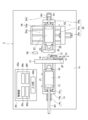
- the automatic lathe (machine tool) 1 includes a first spindle 10 and a tool base 31.
- the first spindle 10 can grip (hold) the work W1 via the chuck.
- This chuck is configured concentrically with the first spindle 10, and is integrally rotatable together with the first spindle 10.
- the work W1 is a long bar in the shape of a round bar, and is supplied from the rear end of the first spindle 10 by using a push arrow of a bar feeder.
- a finger chuck is provided at the tip of the push arrow, and the finger chuck grips the rear end of the work W1.
- the first spindle 10 is rotatably supported by the spindle 12 with the Z1 axis direction shown in FIG. 1 as the axis, and is rotationally driven by the power of the spindle motor 13 provided on the spindle 12.
- the headstock 12 is mounted on the Z1 axial feed mechanism 14 and is movable in the Z1 axial direction.
- the Z1 axial feed mechanism 14 has a Z1 axial rail 14a fixed to the bed 1a and extended in the Z1 axial direction.
- the Z1 axis rail 14a is equipped with a Z1 axis slider 14b that slides along the Z1 axis direction by the Z1 axis motor 14c.
- the headstock 12 is installed on the Z1 axis slider 14b.
- a guide bush 18 for holding a cutting position is provided in front of the headstock 12.
- the guide bush 18 is supported by the support base 17, and the support base 17 is fixed to the bed 1a.
- the work W1 is rotatably supported around the Z1 axis by the guide bush 18, and is sent to the front side of the support base 17.
- the guide bush 18 is provided in front of the first spindle 10 in this way, the material portion having a length from the vicinity of the tip of the first spindle 10 to the guide bush 18 becomes the work residual material W2 that cannot be cut. If the residual material W2 and the newly supplied work W1 are joined, the material can be effectively used, so that the material cost can be reduced.
- a moving table 32 is provided on the front side of the support table 17.
- the moving table 32 moves the tool table 31 in the X1 axis direction orthogonal to the Z1 axis direction, and in the Y1 axis direction orthogonal to the Z1 axis direction and the X1 axis direction.
- a tool 30 whose tip is oriented in the X1 axis direction is mounted on the tool base 31.
- the work W1 can be machined by the tool 30 by moving the first spindle 10 in the Z1 axis direction and moving the tool base 31 in the X1 axis direction or the Y1 axis direction.
- the automatic lathe 1 includes a second spindle 20 at a position facing the first spindle 10.
- the second spindle 20 can grip (hold) the work residual material W2 via the chuck.
- This chuck is configured concentrically with the second spindle 20, and is integrally rotatable together with the second spindle 20.
- the work residual material W2 is, for example, a round bar having the same diameter as the work W1 and is a material left over that cannot be processed by the first spindle 10.
- the work residual material W2 is, for example, transferred from the first spindle 10 to the second spindle 20 and held by the second spindle 20.
- the second spindle 20 is rotatably supported by the spindle 22 with the Z2 axis direction parallel to the Z1 axis as the axis, and is rotationally driven by the power of the spindle motor 23 provided on the spindle 22.
- the headstock 22 is mounted on the Z2 axial feed mechanism 24 and the X2 axial feed mechanism 25, and is movable in the Z2 axial direction and the X2 axial direction.
- the Z2 axial feed mechanism 24 has, for example, a Z2 axial rail 24a arranged on the X2 axial feed mechanism 25 and extending in the Z2 axial direction.
- the Z2-axis rail 24a is equipped with a Z2-axis slider 24b that slides along the Z2-axis direction by the Z2-axis motor 24c.
- the headstock 22 is installed on the Z2-axis slider 24b.
- the X2 axis direction feed mechanism 25 has, for example, an X2 axis rail 25a fixed to the bed 1a and parallel to the X1 axis direction.
- the X2-axis rail 25a is equipped with an X2-axis slider 25b that slides along the X2-axis direction by the X2-axis motor 25c.
- the X2-axis slider 25b is provided with a Z2-axis rail 24a of the Z2-axis direction feed mechanism 24.
- the X2-axis direction feed mechanism 25 corresponds to the second spindle moving means of the present invention, and the X2-axis motor 25c corresponds to the motor of the present invention.
- the rotation of the first spindle 10 and the second spindle 20, the movement of the first spindle 10, the second spindle 20, and the moving table 32 are controlled by the control device 40.
- the control device 40 has a control unit 40a and an input unit 40b, which are connected via a bus.
- the control unit 40a is composed of a CPU, a memory, or the like, and for example, loads various programs and data stored in the ROM into the RAM, and executes this program. Thereby, the operation of the automatic lathe 1 can be controlled based on the program.
- the rotation of the first spindle 10 and the second spindle 20, the movement of the first spindle 10, the second spindle 20, the moving table 32, and the like can be set by a program or by input to the input unit 40b.
- the control unit 40a functions as a misalignment amount detecting means 40c, a current value detecting means 40d, a misalignment direction detecting means 40e, and a rotation angle detecting means 40f.
- the current value detecting means 40d detects the load applied to the X2-axis motor 25c as a current value.
- the misalignment amount detecting means 40c is detected by the current value detecting means 40d while the rear end portion of the work residual material W2 is pressed against the tip portion of the work W1 and integrally joined (upset step U in FIG. 3). Based on the applied load, the misalignment amount s of the work residual material W2 with respect to the integrally joined work W1 is obtained.
- the rotation angle detecting means 40f detects the rotation phase of the first spindle 10.
- the misalignment direction detecting means 40e is used by the misalignment amount detecting means 40c while the rear end portion of the work residual material W2 is pressed against the tip end portion of the work W1 and integrally joined (upset step U in FIG. 3).
- the misalignment direction of the work residual material W2 with respect to the integrally joined work W1 is obtained.
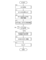
- FIG. 2 is an operation flowchart including misalignment correction
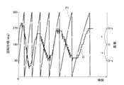
- FIG. 3 shows the rotation speed S1 of the first spindle 10 and the rotation phases P1 and the X2-axis motor 25c in the friction joining (including the friction step M and the upset step U). It is a figure explaining the current value I2 supplied to.
- the length of the work W1 is shortened each time the parting process is performed.
- the machining to the work W1 progresses and the total length of the work W1 held by the first spindle 10 becomes shorter from the vicinity of the tip of the first main shaft 10 to the guide bush 18, this shortened portion becomes a work that cannot be cut. It becomes a residual material.
- a work having a short length held by the first spindle 10 is passed to the second spindle 20.
- the axis of the first spindle 10 and the axis of the second spindle 20 are arranged concentrically, and for example, the second spindle 20 is brought closer to the first spindle 10.
- the chuck of the first spindle 10 is opened, and a new work W1 is supplied from the rear of the first spindle 10.
- the newly supplied work W1 is held by the first spindle 10.
- a short work (which will eventually become the work residual material W2) held by the first main shaft 10 is moved from the guide bush 18 to the front side of the support base 17. Extruded. Therefore, the work residual material W2 is held by the second spindle 20.
- step S10 in FIG. 2 the second spindle 20 is brought closer to the first spindle 10 to form a work residue W2.
- the rear end portion is pressed against the tip portion of the new work W1 so that a predetermined pressure is applied (step S11: start of friction step M).
- step S11 start of friction step M
- the second spindle 20 may also be rotated.
- the first spindle 10 may be rotated in the same direction as the rotation direction of the second spindle 20 or in the opposite direction.
- only the second spindle 20 may be rotated.
- only the second spindle 20 is moved in the Z2 axis direction, but only the first spindle 10 is moved in the Z1 axis direction, or both the first spindle 10 and the second spindle 20 are moved. It is also possible to bring the rear end portion of the work residual material W2 into contact with the front end portion of the work W1.
- Step S12 End of friction step M, start of upset step U.
- the control unit 40a outputs a rotation stop command to the first spindle 10.
- the rotation speed S1 of the first spindle 10 gradually decreases.
- the rotation stop command and the timing of pressing the work residual material W2 against the work W1 by applying a stronger pressure have been described at the same time, but the timing may be different.
- the degree of softening for example, it is possible to know by detecting a decrease in the current value (indicated by I2'in FIG. 3) of the Z2-axis motor 24c. Further, the conditions until the contact portion is softened may be determined in advance by a preliminary experiment, and friction may be applied to the contact portion between the work residual material W2 and the work W1 based on this condition. Then, when the rotation of the first spindle 10 is stopped while pressing the second spindle 20 against the first spindle 10, the rear end portion of the work residual material W2 is joined by pressing the tip portion of the work W1 to be joined to the work residual material W2. Work W1 is integrated.
- the work residual material W2 and the work W1 may be integrated in a misaligned state.
- the temperature of the contact point between the work residual material W2 and the work W1 is high in the upset process U, so that the work residual material W2 is used as the work residual material W2.
- the material W2 can be moved in a direction intersecting the axis of the material W2. Therefore, as shown below, the alignment is performed during the frictional joining (until the joining phenomenon is completed).
- step S11 in FIG. 2 After the work residual material W2 is pressed against the rotating work W1 (step S11 in FIG. 2), the work W1 is gripped by the first spindle 10 and the work residual material W2 is gripped by the second spindle 20.
- the rotation of the first spindle 10 is transmitted to the second spindle 20 via the work W1 and the work residual material W2, so that the second spindle 20 also rotates.
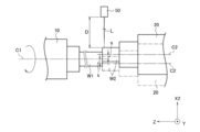
- the second spindle 20 is misaligned with respect to the axis C1 of the first spindle 10, as shown by the solid line and the alternate long and short dash line in FIG. 4, respectively. It vibrates in the X2 axial direction with an amplitude twice the amount (distance between the axial center C1 of the work W1 and the axial center C2 of the work residual material W2) s.
- the position of the second spindle 20 in the X2 axis direction is held by the X2 axis motor 25c, and the X2 axis motor 25c is controlled by the control unit 40a to hold the position of the second spindle 20 in the X2 axis direction.
- the X2-axis motor 25c is in the rotary drive state). Therefore, when vibration due to misalignment is applied to the X2-axis motor 25c, the current value I2 supplied from the control unit 40a to the X2-axis motor 25c increases or decreases according to the rotation phase of the second spindle 20.
- the current value I2 supplied to the X2-axis motor 25c is the X2-axis position (vertical axis) in FIG. As shown by the solid line in the graph of time (horizontal axis), it fluctuates with an amplitude corresponding to twice the amplitude of the misalignment amount s during the upset step U. Therefore, the current value detecting means 40d detects, for example, the fluctuation range (difference between the maximum value and the minimum value) of the current value I2 supplied to the X2-axis motor 25c over a predetermined period.
- the misalignment amount detecting means 40c obtains, for example, an average value of the fluctuation range of the current value I2, and pretends that half of this average value corresponds to the misalignment amount s, and the work residual material for the integrally joined work W1.
- the misalignment amount s of W2 is detected (step S13 in FIG. 2).
- the degree of misalignment between the work W1 and the work residual material W2 can be known by the misalignment amount detecting means 40c during the frictional joining between the work W1 and the work residual material W2. Therefore, as will be described later, the desired work (for example, elimination of misalignment) can be performed by the time the frictional joining is completed. Therefore, after the frictional joining is performed, the joint misalignment can be confirmed and the misaligned workpieces can be corrected. It is not necessary to perform such operations, and further, for example, deburring work can be started promptly. As a result, it is possible to reduce the manufacturing cost of the product and stabilize the quality.
- the load applied to the X2-axis motor 25c has been described by giving an example of obtaining the load applied to the X2-axis motor 25c from the average value of the fluctuation range of the current value I2, but the present invention is not limited to this example.
- the fluctuation range of the current value I2 only at a predetermined timing or the reference value of the fluctuation of the current value I2 may be set, and the amount of increase / decrease with respect to this reference value may be used. Further, other parameters based on the current value I2 may be used.
- the X2-axis motor 25c makes almost one rotation while the spindle motor 13 makes two rotations.
- the current value I2 supplied to the X2-axis motor 25c increases in the positive direction.
- the rotation phase P1 of the first spindle 10 is, for example, 270 °
- the current value I2 supplied to the X2-axis motor 25c is the maximum value. Therefore, it can be seen that the misalignment of the work residual material W2 occurs in the direction connecting the axial center C1 of the first spindle 10 and the position of the rotation phase 270 °.
- step S13 of FIG. 2 (upset step U of FIG. 3), the misalignment direction detecting means 40e rotates with the misalignment amount s of the work residual material W2 with respect to the work W1 detected by the misalignment amount detecting means 40c.
- the misalignment direction of the work residual material W2 with respect to the work W1 is detected.
- the misalignment direction detecting means 40e can know the misalignment direction of the work residual material W2 with respect to the work W1 during the frictional joining between the work W1 and the work residual material W2.
- the control unit 40a determines whether or not the misalignment amount s detected by the misalignment amount detecting means 40c is equal to or greater than a predetermined value that requires correction of the misalignment (step S14 in FIG. 2). Then, when the misalignment amount s detected by the misalignment amount detecting means 40c is equal to or greater than a predetermined value (YES in step S14), the process proceeds to step S15 to correct the misalignment. On the other hand, when the misalignment amount s detected by the misalignment amount detecting means 40c is less than a predetermined value (NO in step S14), the process proceeds to step S17.
- the control unit 40a When it is necessary to correct the misalignment (YES in step S14), the control unit 40a outputs a drive signal to the spindle motor 13 to align the misalignment direction of the work residual material W2 with respect to the work W1 in the X2 direction (step). S15). Specifically, as shown in FIG. 6A, the misalignment direction of the work residual material W2 with respect to the work W1 (the direction connecting the axial center C1 of the work W1 and the axial center C2 of the work residual material W2) is not parallel to the X2 axis. Occasionally, the first spindle 10 is rotated to align this misalignment direction with the X2 axis direction.
- the control unit 40a outputs a drive signal to the X2-axis motor 25c immediately after the first spindle 10 has stopped rotating (indicated by time T3 in FIG. 3), and as shown by an arrow in FIG. 6B.
- the second spindle 20 is moved in the X2 axis direction in the direction in which the misalignment amount s decreases (step S16 in FIG. 2). More specifically, the second spindle 20 is moved in the direction in which the distance from the axis C2 of the work residual material W2 to the axis C1 of the work W1 becomes shorter, for example, by half the average value of the fluctuation range of the current value I2.
- the control unit 40a outputs a drive signal to the Z2-axis motor 24c and further presses the rear end portion of the work residual material W2 against the tip portion of the work W1 to finish the frictional joint (step S17 in FIG. 2). ..
- the temperature at the contact point between the work residual material W2 and the work W1 is high, and the work residual material W2 is the work residual material W2. It suffices as long as it can move in the direction intersecting the axis of. Therefore, in addition to the above-mentioned time T3, for example, immediately before the first spindle 10 stops rotating (shown by the time T2 in FIG. 3), or while the rotation speed S1 of the first spindle 10 is gradually decreasing (time T1). It may be (indicated by).
- the burr generated at the joint portion between the work residual material W2 and the work W1 is cut by the tool 30.
- the tool 30 is arranged closer to the second spindle 20 than the joint portion between the work residual material W2 and the work W1 to set a predetermined depth of cut. Then, while rotating the first spindle 10, the tool 30 is moved closer to the first spindle 10 than the joint portion between the work residual material W2 and the work W1 to remove burrs.
- the front end portion of the work W1 and the rear end portion of the work residual material W2 are frictionally joined using the first spindle 10 and the second spindle 20 arranged to face each other, and the joining and cutting are fused (joining process).
- the automatic lathe 1 that integrates the cutting process and the cutting process can reduce the manufacturing cost of the product.
- the misalignment amount detecting means 40c calculates the misalignment amount s.
- the work with respect to the work W1 is obtained by, for example, photographing the joint portion between the work W1 and the work residual material W2 with a camera and performing image processing, or by measuring with a laser as described later. It can also be applied to detect the amount of misalignment of the residual material W2.
- the example of eliminating (eliminating) the misalignment amount s has been described, but the present invention is also applied to the case where the misalignment amount s is reduced although the misalignment is not eliminated.
- the guide bush 18 can be omitted because it is sufficient that the misalignment amount s can be detected during the frictional joining.
- the work W1 may be made of a material different from the work residual material W2.
- the work W1 and the work residual material W2 may have different diameters.
- the example in which the work residual material W2 and the work W1 are frictionally joined has been described, but the present invention is not limited to the example of joining the work residual material W2, and new materials are joined to each other. It can also be applied when
- the first spindle 10 can rotate around the Z1 axis
- the second spindle 20 can rotate around the Z2 axis
- either the first spindle 10 or the second spindle 20 can rotate in the Z1 axis direction or. It suffices as long as it can move in the Z2 axis direction and either the first spindle 10 or the second spindle 20 can move in the X1 axis direction or the X2 axis direction, and is not limited to the configuration of the embodiment.
- the movement is performed in the direction of the X2 axis orthogonal to the Z2 axis, but in the present invention, the direction can be variously changed as long as the direction intersects the Z2 axis.
- the automatic lathe (machine tool) 2 of the second embodiment is an automatic lathe in which the method of detecting the misalignment amount s of the work residual material W2 with respect to the work W1 in the automatic lathe 1 of the first embodiment is changed. Since many elements of the automatic lathe 2 of the second embodiment are also common to the automatic lathe 1 of the first embodiment, detailed description of common matters will be omitted.
- the automatic lathe 2 has a laser sensor 50, which is a kind of optical sensor controlled by the control device 40, on the bed 1a.
- the laser sensor 50 irradiates the work residual material W2 with the laser beam L in parallel with the X2 axis, and the distance D between the laser sensor 50 and the peripheral side surface of the work residual material W2 in the X2 axis direction. Is detected.
- the detection of the misalignment amount s of the work residual material W2 with respect to the work W1 by the automatic lathe 2 of the second embodiment will be described.
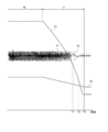
- the distance D between the laser sensor 50 and the peripheral side surface of the work residual material W2 is the distance (vertical axis) and time in FIG.
- the amplitude is twice the misalignment amount s with respect to the distance O in the X2 axis direction between the laser sensor 50 and the peripheral side surface of the work W1. fluctuate.
- the misalignment amount detecting means 40c of the work W1 is based on the output value D of the laser sensor 50 (the distance between the laser sensor 50 and the peripheral side surface of the work residual material W2 in the X2 axial direction).
- the maximum value of the fluctuation value in the X2 axial direction of the peripheral side surface of the work residual material W2 with respect to the axial center C1, that is, the misalignment amount s of the work residual material W2 with respect to the integrally joined work W1 is detected.
- the detection of the misalignment direction of the work residual material W2 with respect to the work W1 by the automatic lathe 2 of the second embodiment will be described.
- the fluctuation (maximum value or minimum value) of the output value D of the laser sensor 50 occurs at substantially the same position during one rotation of the work W1. Therefore, by comparing the fluctuation of the output value D with the rotation phase P1 of the first spindle 10, the misalignment direction of the work residual material W2 with respect to the work W1 can also be known. Specifically, as shown in FIG.
- the rotation phase P1 of the first spindle 10 (indicated by the alternate long and short dash line in the figure) and the output value D of the laser sensor 50 (indicated by the solid line in the figure) are, for example, the spindle.
- the relationship is such that the work residual material W2 makes almost one rotation while the motor 13 (that is, the work W1) makes two rotations.
- the output value D of the laser sensor 50 increases in the positive direction.
- the rotation phase P1 of the first spindle 10 is, for example, 270 °
- the output value D of the laser sensor 50 is the maximum value. Therefore, it can be seen that the misalignment of the work residual material W2 occurs in the direction connecting the axial center C1 of the first spindle 10 and the position of the rotation phase 270 °.
- the misalignment direction detecting means 40e detects the misalignment amount s of the work residual material W2 with respect to the work W1 detected by the misalignment amount detecting means 40c and the rotation angle, as in the first embodiment. By comparing with the rotation phase P1 of the first spindle 10 detected by the means 40f, the misalignment direction of the work residual material W2 with respect to the work W1 is detected. As described above, also in the automatic lathe 2 of the second embodiment, the misalignment direction detecting means 40e allows the misalignment direction of the work residual material W2 with respect to the work W1 to be known during frictional joining between the work W1 and the work residual material W2. ..
- the automatic lathe 2 includes a laser sensor 50 for measuring the distance from the work residual material W2, and the misalignment amount detecting means 40c is based on the output value D of the laser sensor 50.
- the misalignment amount s is directly detected from the shape of the peripheral side surface of the work residual material W2.
- the misalignment amount s can be detected more accurately.
- the laser sensor 50 irradiates the work residual material W2 with a laser in parallel with the X2 axis, and the misalignment amount s and the misalignment of the work residual material W2 with respect to the work W1.
- the direction was detected, any direction may be used as long as the misalignment amount s can be calculated by the misalignment amount detecting means 40c, and the laser irradiation direction to the work residual material W2 is not limited to parallel to the X2 axis. ..
- the laser sensor 50 using the laser beam L has been described as an example of the optical sensor, but the optical sensor is not limited to the laser sensor and is appropriately selected according to the measurement accuracy.
- an optical sensor using emitted light such as LED light may be used.
Landscapes
- Engineering & Computer Science (AREA)
- Mechanical Engineering (AREA)
- Human Computer Interaction (AREA)
- Manufacturing & Machinery (AREA)
- Physics & Mathematics (AREA)
- General Physics & Mathematics (AREA)
- Automation & Control Theory (AREA)
- Turning (AREA)
- Pressure Welding/Diffusion-Bonding (AREA)
- Automatic Control Of Machine Tools (AREA)
Abstract
Description
ワークとワーク残材とを摩擦接合した場合、ワークとワーク残材との芯ずれが生ずることがある。そのため、例えば、特許文献1,2には、摩擦接合中に芯ずれがあるか否かを検出する技術が開示されている。
芯ずれ量検出手段によって、第1ワークと第2ワークの摩擦接合中に、第1ワークと第2ワークとの芯ずれの程度が分かる。よって、この摩擦接合が終わるまでに所望の作業(例えば芯ずれの解消)を実施できるので、この摩擦接合を実施した後に接合ずれの確認や、ずれて接合されたワークの修正等を行う必要がなく、さらに、例えば接合部分のバリ取り作業などを速やかに開始できる。この結果、製品の製造コストの低減や品質安定化を実現することができる。
図1に示すように、自動旋盤(工作機械)1は第1主軸10および工具台31を備えている。第1主軸10は、チャックを介してワークW1を把持(保持)することができる。このチャックは、第1主軸10と同心に構成され、第1主軸10とともに一体的に回転自在である。
第1主軸10は、図1に示すZ1軸方向を軸線として主軸台12に回転自在に支持され、主軸台12に設けられた主軸モータ13の動力によって回転駆動される。主軸台12は、Z1軸方向送り機構14に搭載されており、Z1軸方向に移動自在である。
このように、ガイドブッシュ18を第1主軸10の前方に設けると、第1主軸10の先端付近からガイドブッシュ18までの長さの材料分が、切削できないワーク残材W2となるが、このワーク残材W2と新たに供給されたワークW1とを接合すれば、材料を有効活用できるため、材料コストの削減を図ることができる。
工具台31には、先端をX1軸方向に向けた工具30が装着されている。第1主軸10をZ1軸方向に移動させ、工具台31をX1軸方向またはY1軸方向に移動させることによって、工具30でワークW1を加工することができる。
ワーク残材W2は、例えばワークW1と同径の丸棒であり、第1主軸10で加工できずに余った材料である。ワーク残材W2は、例えば、第1主軸10から第2主軸20に受け渡されて第2主軸20に保持される。
Z2軸方向送り機構24は、例えば、X2軸方向送り機構25上に配置されて、Z2軸方向に延びたZ2軸レール24aを有する。Z2軸レール24aには、Z2軸モータ24cによってZ2軸方向に沿ってスライドするZ2軸スライダ24bが装着されている。このZ2軸スライダ24b上に主軸台22が設置されている。
制御部40aは、CPUやメモリ等からなり、例えばROMに格納されている各種のプログラムやデータをRAMにロードし、このプログラムを実行する。これにより、プログラムに基づいて自動旋盤1の動作を制御できる。
また、制御部40aは、芯ずれ量検出手段40c、電流値検出手段40d、芯ずれ方向検出手段40e、回転角度検出手段40fとして機能している。
電流値検出手段40dは、X2軸モータ25cにかかる負荷を電流値として検出する。芯ずれ量検出手段40cは、ワーク残材W2の後端部分をワークW1の先端部分に押圧して一体接合している間(図3のアップセット工程U)に、電流値検出手段40dで検出した負荷に基づいて、一体接合したワークW1に対するワーク残材W2の芯ずれ量sを求めている。
図1のような自動旋盤1では、突っ切り加工の度にワークW1の長さが短くなる。ワークW1への加工が進み、第1主軸10に保持されていたワークW1の全長が、第1主軸10の先端付近からガイドブッシュ18までくらいに短くなると、この短くなった部分が、切削できないワーク残材になる。このワーク残材を有効活用するために、自動旋盤1では、第1主軸10に保持されていた長さの短いワークを第2主軸20に渡す。
なお、本実施形態においては、回転停止命令と、より強い圧力をかけてワーク残材W2をワークW1に押し付けるタイミングが同時である例を用いて説明したが、このタイミングは異なっていてもよい。
また、軟化の程度の確認方法として、例えば、Z2軸モータ24cの電流値(図3にI2’で示す)の減少を検知することによって、知ることが可能である。また、予備実験によって予め接触箇所が軟化するまでの条件を決定しておき、この条件に基づいてワーク残材W2とワークW1との接触箇所へ摩擦をかけてもよい。
そして、第2主軸20を第1主軸10に押し付けながら第1主軸10の回転が停止すると、ワーク残材W2の後端部分がワークW1の先端部分を押圧して接合され、ワーク残材W2とワークW1が一体化する。
そこで、電流値検出手段40dは、X2軸モータ25cに供給される電流値I2の変動幅(最大値と最小値との差)を例えば所定期間に亘って検出する。そして、芯ずれ量検出手段40cは、この電流値I2の変動幅の例えば平均値を求め、この平均値の半値が芯ずれ量sに相当すると擬制して、一体接合したワークW1に対するワーク残材W2の芯ずれ量sを検出している(図2のステップS13)。
なお、本実施例では、X2軸モータ25cにかかる負荷を電流値I2の変動幅の平均値から求める例を挙げて説明したが、本発明はこの例に限定されない。例えば、所定タイミングのみの電流値I2の変動幅や、電流値I2の変動の基準値を設定しておき、この基準値に対する増減量を用いてもよい。また、電流値I2に基づく他のパラメータを用いてもよい。
詳しくは、図5に示すように、第1主軸10の回転位相P1(図中に1点鎖線で示す)とX2軸モータ25cに供給される電流値I2(図中に実線で示す)とは、例えば、主軸モータ13が2回転する間にX2軸モータ25cがほぼ1回転するような関係にある。そして、ワークW1に対するワーク残材W2の芯ずれ方向が、X2軸の正方向に生じている場合には、X2軸モータ25cに供給される電流値I2が正方向に増加する。また、第1主軸10の回転位相P1が例えば270°のときに、X2軸モータ25cに供給される電流値I2が最大値となっている。よって、ワーク残材W2の芯ずれは、第1主軸10の軸心C1と回転位相270°の位置とを結んだ方向に生じていることが分かる。
なお、第2主軸20をX2軸方向に移動するタイミング(ステップS16)は、ワーク残材W2とワークW1との接触箇所の温度が高くなっており、ワーク残材W2が、このワーク残材W2の軸心に交差する方向に移動できる状態であればよい。このため、上述の時間T3のほか、例えば、第1主軸10が回転停止する直前(図3に時間T2で示す)、または第1主軸10の回転速度S1が次第に減少している間(時間T1で示す)であってもよい。
また、上記実施例では、芯ずれ量sを解消する(なくす)例を挙げて説明したが、本発明は、芯ずれは解消しないが、芯ずれ量sを小さくする場合にも適用される。
また、上記実施例では、Z2軸に直交するX2軸方向に移動させたが、本発明は、Z2軸に交差する方向であれば、その方向は種々変更可能である。
第2実施例の自動旋盤(工作機械)2は、第1実施例の自動旋盤1におけるワークW1に対するワーク残材W2の芯ずれ量sを検出する方法を変更した自動旋盤である。
そして、第2実施例の自動旋盤2の多くの要素も、第1実施例の自動旋盤1と共通するので、共通する事項については詳しい説明を省略する。
例えば、芯ずれ量sの2倍の振幅による振動がワーク残材W2に加わった場合、レーザーセンサー50とワーク残材W2の周側面との距離Dは、図9の距離(縦軸)と時間(横軸)のグラフに実線で示すように、アップセット工程U中に、レーザーセンサー50とワークW1の周側面とのX2軸方向の距離Oを基準に芯ずれ量sの2倍の振幅で変動する。
そこで、芯ずれ量検出手段40cは、アップセット工程Uに、レーザーセンサー50の出力値D(レーザーセンサー50とワーク残材W2の周側面とのX2軸方向の距離)に基づいて、ワークW1の軸心C1に対するワーク残材W2の周側面のX2軸方向の変動値の最大値、すなわち、一体接合したワークW1に対するワーク残材W2の芯ずれ量sを検出している。
第2実施例においてもレーザーセンサー50の出力値Dの変動(最大値や最小値)は、ワークW1の1回転中のほぼ同じ位置に生じている。よって、出力値Dの変動と第1主軸10の回転位相P1とを照らし合わせれば、ワークW1に対するワーク残材W2の芯ずれ方向も分かる。
詳しくは、図9に示すように、第1主軸10の回転位相P1(図中に1点鎖線で示す)とレーザーセンサー50の出力値D(図中に実線で示す)とは、例えば、主軸モータ13(すなわち、ワークW1)が2回転する間にワーク残材W2がほぼ1回転するような関係にある。そして、ワークW1に対するワーク残材W2の芯ずれ方向が、X2軸の正方向に生じている場合には、レーザーセンサー50の出力値Dが正方向に増加する。また、第1主軸10の回転位相P1が例えば270°のときに、レーザーセンサー50の出力値Dが最大値となっている。よって、ワーク残材W2の芯ずれは、第1主軸10の軸心C1と回転位相270°の位置とを結んだ方向に生じていることが分かる。
1a ・・・ ベッド
10 ・・・ 第1主軸
12 ・・・ 主軸台
13 ・・・ 主軸モータ
14 ・・・ Z1軸方向送り機構
14a ・・・ Z1軸レール
14b ・・・ Z1軸スライダ
14c ・・・ Z1軸モータ
17 ・・・ 支持台
18 ・・・ ガイドブッシュ
20 ・・・ 第2主軸
22 ・・・ 主軸台
23 ・・・ 主軸モータ
24 ・・・ Z2軸方向送り機構
24a ・・・ Z2軸レール
24b ・・・ Z2軸スライダ
24c ・・・ Z2軸モータ
25 ・・・ X2軸方向送り機構(第2主軸移動手段)
25a ・・・ X2軸レール
25b ・・・ X2軸スライダ
25c ・・・ X2軸モータ(モータ)
30 ・・・ 工具
31 ・・・ 工具台
32 ・・・ 移動台
40 ・・・ 制御装置
40a ・・・ 制御部
40b ・・・ 入力部
40c ・・・ 芯ずれ量検出手段
40d ・・・ 電流値検出手段
40e ・・・ 芯ずれ方向検出手段
40f ・・・ 回転角度検出手段
50 ・・・ レーザーセンサー(光学式センサー)
W1 ・・・ ワーク(第1ワーク)
W2 ・・・ ワーク残材(第2ワーク)
M ・・・ 摩擦工程
U ・・・ アップセット工程
S1 ・・・ 回転速度
P1 ・・・ 回転位相
I2 ・・・ 電流値
T1 ・・・ 時間
T2 ・・・ 時間
T3 ・・・ 時間
s ・・・ 芯ずれ量
D ・・・ レーザーセンサーとワーク残材の周側面とのX2軸方向の距離
L ・・・ レーザー光
Claims (8)
- 第1ワークを回転自在に保持する第1主軸と、前記第1主軸に対向配置して第2ワークを回転自在に保持する第2主軸と、前記第1主軸に保持された前記第1ワークまたは前記第2主軸に保持された前記第2ワークの少なくともいずれか一方を回転させながら、前記第1主軸と前記第2主軸とが互いに接近するように相対的に移動させて、前記第2ワークの後端部分を前記第1ワークの先端部分に押圧して摩擦接合させる制御部と、を備える工作機械であって、
前記制御部が、前記第1ワークに対する前記第2ワークの芯ずれ量を、前記摩擦接合している間に検出する芯ずれ量検出手段を有する、工作機械。 - 前記芯ずれ量検出手段で検出された前記第1ワークに対する前記第2ワークの芯ずれ量に基づいて、前記摩擦接合している間に、前記第2主軸を前記第2主軸の回転軸線に交差する方向に移動させる第2主軸移動手段を有する、請求項1に記載の工作機械。
- 前記第2主軸を前記第2主軸の回転軸線に交差する方向に移動するタイミングが、前記第1主軸が回転停止した直後、もしくは前記第1主軸が回転停止する直前、または前記第1主軸の回転速度が次第に減少している間である、請求項2に記載の工作機械。
- 前記制御部が、前記芯ずれ量検出手段で検出した前記第1ワークに対する前記第2ワークの芯ずれ量と前記第1主軸の回転位相とを照らし合わせることにより、前記第1ワークに対する前記第2ワークの芯ずれ方向を、前記摩擦接合している間に検出する芯ずれ方向検出手段を有する、請求項1から請求項3のいずれか一項に記載の工作機械。
- 前記第2主軸移動手段が、前記芯ずれ量検出手段で検出された前記第1ワークに対する前記第2ワークの芯ずれ量と前記芯ずれ方向検出手段で検出された前記第1ワークに対する前記第2ワークの芯ずれ方向とに基づいて、前記第2主軸を、前記第1ワークに対する前記第2ワークの芯ずれ量が減少するように前記第2主軸の回転軸線に交差する方向に移動させる、請求項4に記載の工作機械。
- 前記芯ずれ量検出手段が、前記第2主軸の回転軸線に交差する方向に前記第2主軸を移動させるモータにかかる負荷に基づいて、前記第1ワークに対する前記第2ワークの芯ずれ量を求める、請求項1から請求項5のいずれか一項に記載の工作機械。
- 前記芯ずれ量検出手段が、前記第2ワークとの距離を測定する光学式センサーの出力値に基づいて、前記第1ワークに対する前記第2ワークの芯ずれ量を求める、請求項1から請求項5のいずれか一項に記載の工作機械。
- 第1ワークを回転自在に保持する第1主軸と、前記第1主軸に対向配置して前記第1主軸から受け渡された第2ワークを回転自在に保持する第2主軸と、前記第1主軸、および前記第2主軸の動作を制御する制御部と、を備える工作機械の制御方法であって、
前記第1主軸に保持された前記第1ワークまたは前記第2主軸に保持された前記第2ワークの少なくともいずれか一方を回転させながら、前記第1主軸と前記第2主軸とが互いに接近するように相対的に移動させて、前記第2ワークの後端部分を新たに供給された第1ワークの先端部分に接触して摩擦させるステップと、
前記第2ワークの後端部分を前記第1ワークの先端部分に押圧して摩擦接合している間に、前記第1ワークに対する前記第2ワークの芯ずれ量を検出するステップと、
前記摩擦接合している間に、前記第1ワークに対する前記第2ワークの芯ずれ方向を検出するステップと、
前記摩擦接合している間に、検出した前記第1ワークに対する前記第2ワークの芯ずれ量および検出した前記第1ワークに対する前記第2ワークの芯ずれ方向に基づいて、前記第2主軸を、前記第1ワークに対する前記第2ワークの芯ずれ量が減少するように前記第2主軸の回転軸線に交差する方向に移動させるステップと、
を含む、工作機械の制御方法。
Priority Applications (5)
| Application Number | Priority Date | Filing Date | Title |
|---|---|---|---|
| CN202180043055.9A CN115702398B (zh) | 2020-06-30 | 2021-06-28 | 机床、机床的控制方法 |
| US17/923,643 US12269111B2 (en) | 2020-06-30 | 2021-06-28 | Machine tool and control method of machine tool |
| EP21833512.3A EP4129538A4 (en) | 2020-06-30 | 2021-06-28 | MACHINE TOOL AND METHOD FOR CONTROLLING A MACHINE TOOL |
| JP2022533972A JP7604489B2 (ja) | 2020-06-30 | 2021-06-28 | 工作機械、工作機械の制御方法 |
| KR1020227041591A KR20230028251A (ko) | 2020-06-30 | 2021-06-28 | 공작 기계, 공작 기계의 제어 방법 |
Applications Claiming Priority (2)
| Application Number | Priority Date | Filing Date | Title |
|---|---|---|---|
| JP2020-112424 | 2020-06-30 | ||
| JP2020112424 | 2020-06-30 |
Publications (1)
| Publication Number | Publication Date |
|---|---|
| WO2022004625A1 true WO2022004625A1 (ja) | 2022-01-06 |
Family
ID=79315356
Family Applications (1)
| Application Number | Title | Priority Date | Filing Date |
|---|---|---|---|
| PCT/JP2021/024277 Ceased WO2022004625A1 (ja) | 2020-06-30 | 2021-06-28 | 工作機械、工作機械の制御方法 |
Country Status (7)
| Country | Link |
|---|---|
| US (1) | US12269111B2 (ja) |
| EP (1) | EP4129538A4 (ja) |
| JP (1) | JP7604489B2 (ja) |
| KR (1) | KR20230028251A (ja) |
| CN (1) | CN115702398B (ja) |
| TW (1) | TWI887440B (ja) |
| WO (1) | WO2022004625A1 (ja) |
Cited By (1)
| Publication number | Priority date | Publication date | Assignee | Title |
|---|---|---|---|---|
| EP4549059A4 (en) * | 2022-06-30 | 2026-04-22 | Citizen Watch Co Ltd | MACHINE TOOL, AND METHOD FOR ALIGNING MACHINE TOOLS |
Families Citing this family (2)
| Publication number | Priority date | Publication date | Assignee | Title |
|---|---|---|---|---|
| JP7261678B2 (ja) * | 2019-07-04 | 2023-04-20 | シチズン時計株式会社 | 工作機械及び加工方法 |
| CN117161674B (zh) * | 2023-11-02 | 2024-02-09 | 兴化市广福金属制品有限公司 | 一种金属制品对接焊接装置 |
Citations (9)
| Publication number | Priority date | Publication date | Assignee | Title |
|---|---|---|---|---|
| JPS4828265B1 (ja) * | 1969-03-18 | 1973-08-30 | ||
| JPH05177364A (ja) * | 1992-01-08 | 1993-07-20 | Chiyoda Corp | 摩擦圧接機 |
| JPH05208281A (ja) | 1992-01-31 | 1993-08-20 | Nippon Steel Corp | 鋼管の摩擦圧接時の異常検出方法 |
| JPH07195183A (ja) | 1994-01-05 | 1995-08-01 | Hitachi Ltd | 摩擦圧接品の良否判定方法および装置 |
| JPH09285876A (ja) * | 1996-04-23 | 1997-11-04 | Daido Steel Co Ltd | 拡散接合における被接合材の位置合わせ方法 |
| JPH10118777A (ja) * | 1996-10-18 | 1998-05-12 | Toyota Motor Corp | 摩擦圧接方法 |
| JP2000084769A (ja) * | 1998-09-07 | 2000-03-28 | Toyota Autom Loom Works Ltd | クランプ装置及び摩擦圧接装置 |
| WO2019102808A1 (ja) * | 2017-11-27 | 2019-05-31 | シチズン時計株式会社 | 摩擦圧接方法及び工作機械 |
| WO2020149372A1 (ja) * | 2019-01-18 | 2020-07-23 | シチズン時計株式会社 | 工作機械 |
Family Cites Families (21)
| Publication number | Priority date | Publication date | Assignee | Title |
|---|---|---|---|---|
| US3541669A (en) * | 1968-11-20 | 1970-11-24 | Caterpillar Tractor Co | Orienting inertia welded parts |
| JPS4928338B1 (ja) * | 1969-05-12 | 1974-07-25 | ||
| JPS5146634B2 (ja) | 1971-08-18 | 1976-12-10 | ||
| JPS59197389A (ja) * | 1983-04-07 | 1984-11-08 | ロ−ルス−ロイス、パブリック、リミテッド、カンパニ− | 溶接装置 |
| JP2551512B2 (ja) | 1992-01-07 | 1996-11-06 | 新日本製鐵株式会社 | 高Crフェライト系耐熱鋼用溶接材料 |
| US5858142A (en) * | 1997-02-27 | 1999-01-12 | Inertia Friction Welding, Inc. | Angular orientation control system for friction welding |
| BE1012692A3 (nl) | 1999-06-01 | 2001-02-06 | Denys Nv | Werkwijze en inrichting voor het lassen van langwerpige elementen. |
| DE10330188A1 (de) * | 2003-07-03 | 2005-02-03 | Kuka Schweissanlagen Gmbh | Verfahren und Vorrichtung zum Pressschweißen |
| DE102004001274A1 (de) * | 2004-01-08 | 2005-08-04 | Mtu Aero Engines Gmbh | Rotationsreibschweißanlage |
| GB0418524D0 (en) * | 2004-08-19 | 2004-09-22 | Rolls Royce Plc | Process and apparatus for inertia friction welding |
| US20070051776A1 (en) * | 2005-07-06 | 2007-03-08 | Ssd Control Technology, Inc. | Dual friction welder |
| JP5243083B2 (ja) * | 2008-04-01 | 2013-07-24 | 株式会社豊田自動織機 | 摩擦圧接方法 |
| EP2561948A1 (de) * | 2011-08-24 | 2013-02-27 | Wartmann Technologie AG | Verfahren und Anlage zum Herstellen eines Flansch-Rohr-Flansch-Elementes mittels Rührreibschweissen |
| JP5815462B2 (ja) * | 2012-04-26 | 2015-11-17 | Dmg森精機株式会社 | 旋盤におけるワークの芯ずれ補正機構。 |
| DE202012103219U1 (de) * | 2012-08-24 | 2013-12-02 | Kuka Systems Gmbh | Pressschweißvorrichtung |
| JP6155155B2 (ja) * | 2013-09-27 | 2017-06-28 | 三菱重工業株式会社 | 摩擦撹拌工具、摩擦撹拌接合装置及び摩擦撹拌接合方法 |
| US10268176B2 (en) * | 2014-03-26 | 2019-04-23 | Citizen Watch Co., Ltd. | Control device for machine tool and machine tool including the control device |
| GB201413923D0 (en) * | 2014-08-06 | 2014-09-17 | Rolls Royce Plc | Rotary friction welding |
| GB201501884D0 (en) * | 2015-02-05 | 2015-03-25 | Rolls Royce Plc | Friction welding |
| DE102015102353A1 (de) * | 2015-02-19 | 2016-08-25 | Kuka Industries Gmbh | Verfahren und Vorrichtung zum Reibschweißen |
| WO2018181447A1 (ja) * | 2017-03-29 | 2018-10-04 | シチズン時計株式会社 | 工作機械の制御装置および工作機械 |
-
2021
- 2021-06-28 WO PCT/JP2021/024277 patent/WO2022004625A1/ja not_active Ceased
- 2021-06-28 CN CN202180043055.9A patent/CN115702398B/zh active Active
- 2021-06-28 JP JP2022533972A patent/JP7604489B2/ja active Active
- 2021-06-28 EP EP21833512.3A patent/EP4129538A4/en active Pending
- 2021-06-28 TW TW110123935A patent/TWI887440B/zh active
- 2021-06-28 US US17/923,643 patent/US12269111B2/en active Active
- 2021-06-28 KR KR1020227041591A patent/KR20230028251A/ko active Pending
Patent Citations (9)
| Publication number | Priority date | Publication date | Assignee | Title |
|---|---|---|---|---|
| JPS4828265B1 (ja) * | 1969-03-18 | 1973-08-30 | ||
| JPH05177364A (ja) * | 1992-01-08 | 1993-07-20 | Chiyoda Corp | 摩擦圧接機 |
| JPH05208281A (ja) | 1992-01-31 | 1993-08-20 | Nippon Steel Corp | 鋼管の摩擦圧接時の異常検出方法 |
| JPH07195183A (ja) | 1994-01-05 | 1995-08-01 | Hitachi Ltd | 摩擦圧接品の良否判定方法および装置 |
| JPH09285876A (ja) * | 1996-04-23 | 1997-11-04 | Daido Steel Co Ltd | 拡散接合における被接合材の位置合わせ方法 |
| JPH10118777A (ja) * | 1996-10-18 | 1998-05-12 | Toyota Motor Corp | 摩擦圧接方法 |
| JP2000084769A (ja) * | 1998-09-07 | 2000-03-28 | Toyota Autom Loom Works Ltd | クランプ装置及び摩擦圧接装置 |
| WO2019102808A1 (ja) * | 2017-11-27 | 2019-05-31 | シチズン時計株式会社 | 摩擦圧接方法及び工作機械 |
| WO2020149372A1 (ja) * | 2019-01-18 | 2020-07-23 | シチズン時計株式会社 | 工作機械 |
Non-Patent Citations (1)
| Title |
|---|
| See also references of EP4129538A4 |
Cited By (1)
| Publication number | Priority date | Publication date | Assignee | Title |
|---|---|---|---|---|
| EP4549059A4 (en) * | 2022-06-30 | 2026-04-22 | Citizen Watch Co Ltd | MACHINE TOOL, AND METHOD FOR ALIGNING MACHINE TOOLS |
Also Published As
| Publication number | Publication date |
|---|---|
| EP4129538A4 (en) | 2024-04-17 |
| CN115702398B (zh) | 2025-07-01 |
| EP4129538A1 (en) | 2023-02-08 |
| TW202204074A (zh) | 2022-02-01 |
| JP7604489B2 (ja) | 2024-12-23 |
| US20230182230A1 (en) | 2023-06-15 |
| TWI887440B (zh) | 2025-06-21 |
| JPWO2022004625A1 (ja) | 2022-01-06 |
| US12269111B2 (en) | 2025-04-08 |
| CN115702398A (zh) | 2023-02-14 |
| KR20230028251A (ko) | 2023-02-28 |
Similar Documents
| Publication | Publication Date | Title |
|---|---|---|
| KR102705949B1 (ko) | 공작 기계 | |
| WO2022004625A1 (ja) | 工作機械、工作機械の制御方法 | |
| US11338386B2 (en) | Friction welding method and machine tool | |
| TWI809242B (zh) | 工作機械 | |
| US12162078B2 (en) | Machine tool | |
| JP7312762B2 (ja) | 工作機械 | |
| CN113950384A (zh) | 机床和加工方法 | |
| WO2021193344A1 (ja) | 工作機械、工作機械の制御方法 | |
| JP2024150161A (ja) | 摩擦接合装置及び摩擦接合方法 | |
| TW202019588A (zh) | 工作機械 | |
| KR20120005708A (ko) | 마찰 압접기 및 마찰 압접 방법 | |
| JP2018187738A (ja) | 工作機械 |
Legal Events
| Date | Code | Title | Description |
|---|---|---|---|
| 121 | Ep: the epo has been informed by wipo that ep was designated in this application |
Ref document number: 21833512 Country of ref document: EP Kind code of ref document: A1 |
|
| ENP | Entry into the national phase |
Ref document number: 2022533972 Country of ref document: JP Kind code of ref document: A |
|
| ENP | Entry into the national phase |
Ref document number: 2021833512 Country of ref document: EP Effective date: 20221025 |
|
| ENP | Entry into the national phase |
Ref document number: 20227041591 Country of ref document: KR Kind code of ref document: A |
|
| NENP | Non-entry into the national phase |
Ref country code: DE |
|
| WWG | Wipo information: grant in national office |
Ref document number: 17923643 Country of ref document: US |
|
| WWG | Wipo information: grant in national office |
Ref document number: 202180043055.9 Country of ref document: CN |