WO2022004814A1 - Dispositif de coussin de sécurité gonflable pour un piéton - Google Patents
Dispositif de coussin de sécurité gonflable pour un piéton Download PDFInfo
- Publication number
- WO2022004814A1 WO2022004814A1 PCT/JP2021/024831 JP2021024831W WO2022004814A1 WO 2022004814 A1 WO2022004814 A1 WO 2022004814A1 JP 2021024831 W JP2021024831 W JP 2021024831W WO 2022004814 A1 WO2022004814 A1 WO 2022004814A1
- Authority
- WO
- WIPO (PCT)
- Prior art keywords
- partition wall
- expands
- pillar
- pedestrian
- chamber
- Prior art date
- Legal status (The legal status is an assumption and is not a legal conclusion. Google has not performed a legal analysis and makes no representation as to the accuracy of the status listed.)
- Ceased
Links
Images



Classifications
-
- B—PERFORMING OPERATIONS; TRANSPORTING
- B60—VEHICLES IN GENERAL
- B60R—VEHICLES, VEHICLE FITTINGS, OR VEHICLE PARTS, NOT OTHERWISE PROVIDED FOR
- B60R21/00—Arrangements or fittings on vehicles for protecting or preventing injuries to occupants or pedestrians in case of accidents or other traffic risks
- B60R21/34—Protecting non-occupants of a vehicle, e.g. pedestrians
- B60R21/36—Protecting non-occupants of a vehicle, e.g. pedestrians using airbags
-
- B—PERFORMING OPERATIONS; TRANSPORTING
- B60—VEHICLES IN GENERAL
- B60R—VEHICLES, VEHICLE FITTINGS, OR VEHICLE PARTS, NOT OTHERWISE PROVIDED FOR
- B60R21/00—Arrangements or fittings on vehicles for protecting or preventing injuries to occupants or pedestrians in case of accidents or other traffic risks
- B60R2021/0002—Type of accident
- B60R2021/0004—Frontal collision
-
- B—PERFORMING OPERATIONS; TRANSPORTING
- B60—VEHICLES IN GENERAL
- B60R—VEHICLES, VEHICLE FITTINGS, OR VEHICLE PARTS, NOT OTHERWISE PROVIDED FOR
- B60R21/00—Arrangements or fittings on vehicles for protecting or preventing injuries to occupants or pedestrians in case of accidents or other traffic risks
- B60R21/34—Protecting non-occupants of a vehicle, e.g. pedestrians
- B60R2021/346—Protecting non-occupants of a vehicle, e.g. pedestrians means outside vehicle body
Definitions
- the present invention relates to a pedestrian airbag device provided with an airbag cushion that expands and expands from below the front hood of the vehicle toward the windshield.
- a pedestrian airbag device that protects pedestrians outside the vehicle has been developed as an airbag device that is different from the one that restrains the occupants inside the vehicle.
- the airbag cushion expands to a part such as a windshield where the pedestrian's body may come into contact. It is configured to be deployed.
- the airbag 11 in order to prevent a pedestrian from coming into contact with the highly rigid A pillar 5, the airbag 11 is provided with a pillar covering portion 11b that covers the A pillar 5.
- the main portion 11a and the pillar covering portion 11b of the airbag 11 are partitioned by a partition cloth 20, and a tether 40 serving as a check valve is provided in the gas passage opening 23 of the partition cloth 20.
- the pressure of the pillar covering portion 11b is kept high.
- the partition cloth 20 of Patent Document 1 may be stretched when a force is applied because the gas passage opening 23 is open.
- FIG. 9A of Patent Document 1 when the upper panel 15 and the lower panel 16 move in a direction away from each other due to the pressure of gas, the partition cloth 20 is pulled in the vertical direction.
- the partition cloth 20 is excessively stretched, the tether 40 may be stretched and it may be difficult to separate from the gas passage opening 23. If the tether 40 is difficult to separate from the gas passage opening 23, the inflow of gas into the pillar covering portion 11b is hindered, and the protection of pedestrians on the A pillar 5 becomes insufficient.
- a typical configuration of the pedestrian airbag device is an airbag cushion that expands and expands from below the front hood of the vehicle toward the windshield, and gas in the airbag cushion.
- the airbag cushion receives gas from the inflator and expands and expands to cover at least the bottom of the windshield, and both ends of the main chamber in the vehicle width direction.
- a pillar chamber that is installed in the main chamber and expands to cover the A pillar, a partition wall that separates the main chamber and the pillar chamber, and an inner vent that penetrates the partition wall and allows gas to pass through. It is characterized by having a bridge spanned over the inner vent and a patch attached to the pillar chamber side of the compartment wall to cover the inner vent and partly separable from the compartment wall.
- the inner vent since the inner vent is bridged, it is possible to suppress the spread of the inner vent and also suppress the elongation of the partition wall and the patch.
- the patch when the partition wall is pulled in a predetermined direction, the patch can be prevented from being stretched and stretched, so that the slack of the patch can be maintained. That is, with the above configuration, the patch can be kept in a state where it can be separated from the partition wall, which makes it possible to realize smooth expansion and deployment of the pillar chamber and sufficient protection of pedestrians.
- the above main chamber expands and expands in a state where it receives gas from the inflator and extends in the vehicle width direction so as to cover at least the lower part of the windshield
- the pillar chamber receives gas from the main chamber and expands to cover the vehicle width of the main chamber. It expands and expands from both sides of the direction along the A pillar to the rear of the vehicle from the door mirror of the vehicle, and the partition wall is formed at a predetermined position on the trailing edge of the airbag cushion from the main chamber to the pillar chamber. It is characterized in that it is provided in the range between the first virtual line extending from the inner angle to the front of the vehicle and the second virtual line extending in the vehicle width direction along the rear end of the door mirror.
- the range from the first virtual line to the second virtual line of the above airbag cushion is the highly rigid part of the front part of the vehicle such as the end of the side of the hood of the vehicle, the A pillar, and the door mirror. It is the range to cover.
- a part of the above main chamber may be expanded and expanded so as to overlap the upper side near the rear end of the front hood.
- the main chamber of this configuration also makes it possible to adequately protect pedestrians.
- the above patch may have slack so that it can be separated from the partition wall.
- the patch is preferably able to pass gas by separating the slack portion from the partition wall.
- the slack of the above patch may be formed by attaching at least two patch slacks at a predetermined interval to two locations on the partition wall at intervals shorter than the interval. This configuration makes it possible to suitably realize a patch with slack.
- the above bridge may be provided so as to divide the inner vent in the vehicle width direction when the airbag cushion expands and expands.
- the bridge of this configuration can prevent the inner vent and the partition wall from extending in the vertical direction.
- the above bridge may be provided so as to divide the inner vent into upper and lower parts when the airbag cushion expands and expands.
- the bridge of this configuration can prevent the inner vent and the partition wall from extending in the vehicle width direction.
- the above bridges may be provided in a shape that intersects within the inner vent.
- the bridge in this configuration makes it possible to more efficiently suppress accidental deformation of inner vents and partition walls.
- a pedestrian airbag device capable of fully protecting a pedestrian on an A-pillar.
- FIG. 1 It is a figure which illustrates the outline of the pedestrian airbag device which concerns on embodiment of this invention. It is a figure which enlarged and illustrated the left side of the airbag cushion of FIG. 1 (a) in the vehicle width direction from above. It is a figure which illustrated the partition wall of the airbag cushion of FIG. 2 from each direction. It is a schematic diagram at the time of pedestrian restraint in the airbag cushion of FIG. It is a figure exemplifying each deformation example of the partition wall of FIG. 3A. It is a figure exemplifying the modification of the airbag cushion of FIG.
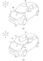
- FIG. 1 is a diagram illustrating an outline of the pedestrian airbag device 100 according to the embodiment of the present invention.
- FIG. 1A is a diagram illustrating a vehicle before the operation of the pedestrian airbag device 100
- FIG. 1B is a diagram illustrating a vehicle when the pedestrian airbag device 100 is activated.
- the front and rear directions of the vehicle are arrows F (Forward) and B (Back)
- the left and right directions of the vehicle width are arrows L (Left) and R (Right)
- the vehicle up and down directions are arrows, respectively. Examples are U (up) and D (down).
- the pedestrian airbag device 100 is installed under the front hood 104 of the vehicle 102.
- the pedestrian airbag device 100 includes a sensor (not shown) at a location where a pedestrian's leg or the like is likely to come into contact, such as inside the vicinity of the front bumper 106.
- a sensor detects contact with a pedestrian
- an operation signal is transmitted to the inflator 112, which is a gas generator, via a control unit or the like, and the airbag cushion 114 is moved from below the front hood 104 as shown in FIG. 1 (b). It is a mechanism that expands and expands toward the windshield 108.
- the pedestrian airbag device 100 includes a housing 116 that houses the airbag cushion 114.
- the housing 116 is a long box-shaped container mainly made of resin, and houses an airbag cushion 114 (see FIG. 1B), an inflator 112, and the like.
- the housing 116 is attached to the lower surface of the front hood 104 via a dedicated bracket or the like with its longitudinal direction facing the vehicle width direction.
- the inflator 112 is fixed inside the housing 116 using stud bolts (not shown) and operates due to an impact detection signal sent from a predetermined sensor to supply gas to the airbag cushion 114. ..
- the airbag cushion 114 begins to expand due to the gas from the inflator 112, and the expansion pressure causes the housing 116 to be cleaved and expanded toward the windshield 108.
- the inflator 112 is a cylinder type (cylindrical type) in this embodiment.
- Currently popular inflators are filled with a gas generator and burned to generate gas, compressed gas is filled with gas to supply gas without generating heat, or combustion.
- the airbag cushion 114 in the present embodiment expands and expands along the windshield 108 and receives a pedestrian who tries to come into contact with the windshield 108.
- the airbag cushion 114 lifts the front hood 104 and lifts it slightly. This operation has the effect of cushioning the impact on the pedestrian in contact with the front hood 104.
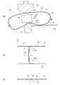
- FIG. 2 is an example in which the left side of the airbag cushion 114 in FIG. 1A in the vehicle width direction is enlarged from above.
- the airbag cushion 114 has a bag shape, and is formed by stacking and sewing or adhering a plurality of base fabrics constituting the surface thereof, or by spinning using OPW (One-Piece Woven).
- the expansion region of the airbag cushion 114 in which gas flows in and expands is divided into two chambers, a main chamber 118 and a pillar chamber 120.
- the main chamber 118 receives gas from the inflator 112, expands and expands so as to cover at least the lower part of the windshield 108, and widely receives the walking body.
- the pillar chamber 120 is provided at both ends of the main chamber 118 in the vehicle width direction, receives gas from the main chamber 118, expands and expands so as to cover the A pillar 110, and has a highly rigid A pillar such as a pedestrian's head. Prevent contact with 110.
- the main chamber 118 may be configured to lift the vicinity of the rear end of the front hood 104 from below, or may be configured to expand and expand so as to overlap the upper side of the vicinity of the rear end of the front hood 104.
- the main chamber 118 lifts the vicinity of the rear end of the front hood 104, it is possible to soften the impact given when a pedestrian comes into contact with the front hood 104 by floating the front hood 104. Further, when the main chamber 118 overlaps and expands on the upper side near the rear end of the front hood 104, it becomes possible to protect the pedestrian over a wider range.
- a partition wall 122 that separates the main chamber 118 and the pillar chamber 120 is provided inside the airbag cushion 114.
- the partition wall 122 can be provided, for example, at a position overlapping near the root of the A pillar 110.
- a check valve structure is provided on the partition wall 122 so that the internal pressure of the pillar chamber 120 can be kept high for a longer period of time.
- FIG. 3 is a diagram illustrating the partition wall 122 of the airbag cushion 114 of FIG. 2 from each direction.
- FIG. 3A is an arrow view A of the partition wall 122 inside the airbag cushion 114 of FIG.
- the airbag cushion 114 includes an upper outer panel 124 and a lower inner panel 126.
- the partition wall 122 separates the main chamber 118 (see FIG. 2) and the pillar chamber 120 by partitioning the outer panel 124 and the inner panel 126 without a gap.
- the check valve structure of the partition wall 122 is realized by the inner vent 128 provided on the partition wall 122 and the patch 130 covering the inner vent 128.
- the inner vent 128 is a place through which gas passes, and is provided as a through hole penetrating the partition wall 122.
- the patch 130 is attached to the partition wall 122 so as to cover the inner vent 128 on the pillar chamber 120 side of the partition wall 122.
- the upper edge 132 and the lower edge 134 are connected to the partition wall 122 by the sewing portion 136a and the sewing portion 136b, respectively, and the central portion other than the upper edge 132 and the lower edge 134 is slackened to form the partition wall 122. It is possible to separate from.
- a bridge 138 is passed over the inner vent 128.
- the bridge 138 plays a role of reinforcing the inner vent 128, and prevents the partition wall 122 from being easily stretched by opening the inner vent 128.
- the bridge 138 extends in the vertical direction so as to divide the inner vent 128 in the vehicle width direction when the airbag cushion 114 expands and expands.
- the bridge 138 having this configuration makes it difficult for the inner vent 128 and the partition wall 122 to extend in the vertical direction.
- FIG. 3B is a sectional view taken along the line BB of the airbag cushion 114 of FIG. 3A. Further, FIG. 3B illustrates the state of the patch 130 when the gas flows from the main chamber 118 to the pillar chamber 120. When gas pressure is applied from the main chamber 118 toward the pillar chamber 120 during expansion and deployment of the airbag cushion 114, the central slack 137 portion of the patch 130 is separated from the partition wall 122 toward the pillar chamber 120 by the pressure. ..
- the upper edge 132 and the lower edge 134 which are spaced above and below the patch 130, are spaced apart from each other on the partition wall 122, which is shorter than the distance between the upper edge 132 and the lower edge 134. It is in a state of being formed by being attached to the sewn portion 136a and the sewn portion 136b. With this configuration, the patch 130 has a slack 137 formed, and when a gas pressure is applied from the main chamber 118 side, the portion of the slack 137 can pass the gas away from the partition wall 122.
- FIG. 3 (c) is a cross-sectional view taken along the line CC in the vicinity of the partition wall 122 of FIG. 3 (a).
- the patch 130 has a portion of the slack 137 separated from the partition wall 122 by the gas flowing through the inner vent 128 from the main chamber 118 (see FIG. 3B) toward the pillar chamber 120.
- the slack 137 in the center of the patch 130 is separated from the partition wall 122, so that the pillar chamber 120 can be smoothly expanded and expanded.
- FIG. 4 is a schematic view of the airbag cushion 114 of FIG. 3 when a pedestrian is restrained.
- FIG. 4A shows a state of the airbag cushion 114 of FIG. 3A when the pedestrian is restrained.
- FIG. 4A exemplifies a state in which an impactor 140, which is a test device imitating a pedestrian's head, is made to collide with the pillar chamber 120.
- the pillar chamber 120 expands and expands so as to cover the ends of the A pillar 110 and the windshield 108 to prevent pedestrians from colliding with the vicinity of the highly rigid A pillar 110.
- FIG. 4 (b) shows the state of the airbag cushion 114 of FIG. 3 (b) when the pedestrian is restrained.
- FIG. 4 (c) shows a state when a pedestrian is restrained in the vicinity of the partition wall 122 of FIG. 3 (c). As described above, when the pedestrian is restrained, the patch 130 closes the inner vent 128 to maintain the internal pressure of the pillar chamber 120.
- the internal pressure of the pillar chamber 120 is appropriately maintained by the check valve structure using the partition wall 122 and the patch 130, and the A pillar 110 having high rigidity can be obtained. It is possible to suitably protect pedestrians from contact.
- the general A-pillar 110 has a narrower width than the pedestrian's head imitated by the impactor 140, and the airbag cushion 114 is used when the pedestrian's head is restrained. It is difficult to obtain reaction force from the A pillar 110.
- by increasing the internal pressure of the pillar chamber 120 a reaction force can be suitably obtained from the narrow A pillar 110, and the head of the pedestrian can be fully restrained.
- the expansion of the inner vent 128 can be suppressed and the elongation of the partition wall 122 and the patch 130 can also be suppressed.
- FIG. 3B when gas is supplied to the airbag cushion 114, the partition wall 122 is pulled by the outer panel 124 and the inner panel 126 trying to separate from each other. At this time, the extension of the partition wall 122 is suppressed by suppressing the spread of the inner vent 128 by the bridge 138.
- the partition wall 122 is deformed so as to extend, the upper edge 132 and the lower edge 134 of the patch 130 are pulled in a direction in which the patch 130 is separated from each other, and the patch 130 is in a stretched state without slack and becomes difficult to separate from the partition wall 122.
- the patch 130 is kept in a state where it can be separated from the partition wall 122 by suppressing the elongation of the partition wall 122 and the patch 130, whereby the pillar chamber 120 is smoothly expanded and deployed and the pedestrian is fully developed. It is possible to realize the protection.
- the bridge 138 can prevent the thickness of the pillar chamber 120 from being excessively increased. As the thickness of the pillar chamber 120 increases, the overall capacity of the airbag cushion 114 also increases, and as a result, the internal pressure of the airbag cushion 114 decreases. In the present embodiment, the bridge 138 suppresses the elongation of the partition wall 122 to suppress the thickness of the pillar chamber 120, maintains the internal pressure and reaction force of the airbag cushion 114, and walks in the entire range of the airbag cushion 114. It is possible to accept the person appropriately.
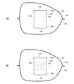
- FIG. 5 is a diagram illustrating each modification of the partition wall 122 of FIG. 3A.
- the same components as those already described are designated by the same reference numerals, so that the description of the existing components will be omitted.
- those having the same name as the component already described shall have the same function even if they have different reference numerals, unless otherwise specified.
- FIG. 5 (a) is a first modification (partition wall 160) of the partition wall 122 of FIG. 3 (a).
- the bridge 164 extends along the vehicle width direction so as to divide the inner vent 162 in the vertical direction when the airbag cushion 114 expands and expands.
- the inner vent 162 and the partition wall 160 are difficult to extend in the vehicle width direction.
- the patch 130 can be kept in a state where it can be separated from the partition wall 160 even when a pulling force is easily applied to the partition wall 160 in the vehicle width direction, whereby the pillar chamber 120 can be smoothly expanded. It is possible to achieve deployment and full protection of pedestrians.
- FIG. 5 (b) is a second modification (partition wall 180) of the partition wall 122 of FIG. 3 (a).
- the bridge 184 is provided so as to intersect within the inner vent 182.
- the inner vent 182 and the partition wall 180 are difficult to extend in either the vertical direction or the vehicle width direction.
- the patch 130 can be kept in a state where it can be separated from the partition wall 180 even when a pulling force is easily applied to the partition wall 180 in the vertical direction and the vehicle width direction, whereby the pillar chamber 120 can be separated from the partition wall 180. It is possible to realize smooth expansion and deployment and full protection of pedestrians.
- FIG. 6 is a diagram illustrating a modified example (airbag cushion 200) of the airbag cushion 114 of FIG.
- the inside of the airbag cushion 200 is also partitioned by the partition wall 122.
- the main chamber 202 expands and expands in a state of extending in the vehicle width direction so as to cover the lower part of the windshield 108.
- the pillar chamber 204 receives gas from the main chamber 202 and extends from both sides of the main chamber 202 in the vehicle width direction to the extent that it reaches the rear of the vehicle along the A pillar 110 from the door mirror 109 of the vehicle. It expands and expands to the state where it is.
- the airbag cushion 200 can provide the partition wall 122 at a predetermined position within the range exemplified by the first virtual line L1 and the second virtual line L2.
- the first virtual line L1 is a straight line virtually extending to the front of the vehicle from an internal angle 208 formed in the middle of the trailing edge of the airbag cushion 200 from the main chamber 202 to the pillar chamber 204.
- the second virtual line L2 is a straight line virtually extended in the vehicle width direction along the rear end 111 of the door mirror 109.
- the partition wall 122 is a member that separates the main chamber 202 and the pillar chamber 204. That is, in this modification, the airbag cushion 200 can be divided into the main chamber 202 and the pillar chamber 204 within the range from the first virtual line L1 to the second virtual line L2.
- the patch 130 can be kept in a state where it can be separated from the partition wall 122 by suppressing the elongation of the partition wall 122 and the patch 130 (see FIG. 3A). Thereby, even in this modification, it is possible to realize smooth expansion and deployment of the pillar chamber 204 on the terminal side of the partition wall 122 of the airbag cushion 200 and sufficient protection of pedestrians.
- the range from the first virtual line L1 to the second virtual line L2 of the airbag cushion 200 is the front part of the vehicle such as the end 113 on the side of the hood of the vehicle, the A pillar 110, and the door mirror 109. Above all, it is the range that covers the highly rigid part.
- the partition wall 122 By providing the partition wall 122 in this range, the expansion pressure of the pillar chamber 204 on the terminal side of the partition wall 122 of the airbag cushion 200 can be suitably maintained, and the rigidity of the A pillar 110, the door mirror 109, and the like can be suitably maintained. It is possible to completely prevent pedestrians from coming into contact with the high part of the pedestrian.
- the present invention can be used for a pedestrian airbag device provided with an airbag cushion that expands and expands from below the front hood of the vehicle toward the windshield.
- Pedestrian airbag device 102 ... Vehicle, 104 ... Front hood, 106 ... Front bumper, 108 ... Windshield, 109 ... Door mirror, 110 ... A pillar, 112 ... Inflator, 113 ... End, 114 ... Airbag Cushion, 116 ... housing, 118 ... main chamber, 120 ... pillar chamber, 122 ... partition wall, 124 ... outer panel, 126 ... inner panel, 128 ... inner vent, 130 ... patch, 132 ... upper edge, 134 ... lower edge, 136a, 136b ... Sewing part, 137 ... Slack, 138 ... Bridge, 140 ... Impactor, 160 ... First variant partition wall, 162 ...
Landscapes
- Engineering & Computer Science (AREA)
- Mechanical Engineering (AREA)
- Air Bags (AREA)
Abstract
Priority Applications (4)
| Application Number | Priority Date | Filing Date | Title |
|---|---|---|---|
| US18/003,844 US12275368B2 (en) | 2020-07-03 | 2021-06-30 | Airbag device for pedestrian |
| JP2022534095A JP7361923B2 (ja) | 2020-07-03 | 2021-06-30 | 歩行者用エアバッグ装置 |
| CN202180039873.1A CN115702096A (zh) | 2020-07-03 | 2021-06-30 | 步行者用安全气囊装置 |
| EP21834294.7A EP4177116A4 (fr) | 2020-07-03 | 2021-06-30 | Dispositif de coussin de sécurité gonflable pour un piéton |
Applications Claiming Priority (2)
| Application Number | Priority Date | Filing Date | Title |
|---|---|---|---|
| JP2020115352 | 2020-07-03 | ||
| JP2020-115352 | 2020-07-03 |
Publications (1)
| Publication Number | Publication Date |
|---|---|
| WO2022004814A1 true WO2022004814A1 (fr) | 2022-01-06 |
Family
ID=79316367
Family Applications (1)
| Application Number | Title | Priority Date | Filing Date |
|---|---|---|---|
| PCT/JP2021/024831 Ceased WO2022004814A1 (fr) | 2020-07-03 | 2021-06-30 | Dispositif de coussin de sécurité gonflable pour un piéton |
Country Status (5)
| Country | Link |
|---|---|
| US (1) | US12275368B2 (fr) |
| EP (1) | EP4177116A4 (fr) |
| JP (1) | JP7361923B2 (fr) |
| CN (1) | CN115702096A (fr) |
| WO (1) | WO2022004814A1 (fr) |
Families Citing this family (2)
| Publication number | Priority date | Publication date | Assignee | Title |
|---|---|---|---|---|
| WO2022004814A1 (fr) * | 2020-07-03 | 2022-01-06 | オートリブ ディベロップメント エービー | Dispositif de coussin de sécurité gonflable pour un piéton |
| JP7660009B2 (ja) * | 2021-03-29 | 2025-04-10 | 株式会社Subaru | エアバッグ装置 |
Citations (7)
| Publication number | Priority date | Publication date | Assignee | Title |
|---|---|---|---|---|
| US3820814A (en) * | 1971-04-03 | 1974-06-28 | Daimler Benz Ag | Discharge valve for an air bag |
| JPH07329693A (ja) * | 1994-06-10 | 1995-12-19 | Takata Kk | エアバッグの内圧調節装置 |
| JP2000052916A (ja) * | 1998-08-03 | 2000-02-22 | Takata Kk | エアバッグ |
| JP2013193492A (ja) * | 2012-03-16 | 2013-09-30 | Takata Corp | エアバッグ及びエアバッグ装置 |
| JP2015157616A (ja) * | 2013-04-26 | 2015-09-03 | タカタ株式会社 | エアバッグ装置及びエアバッグの折り畳み方法 |
| JP2017171269A (ja) | 2016-03-22 | 2017-09-28 | タカタ株式会社 | 歩行者用エアバッグ装置及び自動車 |
| JP2019151203A (ja) * | 2018-03-02 | 2019-09-12 | 豊田合成株式会社 | 歩行者用エアバッグ |
Family Cites Families (25)
| Publication number | Priority date | Publication date | Assignee | Title |
|---|---|---|---|---|
| DE10014832B4 (de) * | 2000-03-24 | 2006-05-04 | Volkswagen Ag | Sicherheitssystem für ein Kraftfahrzeug |
| DE102006033670B4 (de) * | 2005-07-26 | 2011-08-25 | Honda Motor Co., Ltd. | Fahrzeug mit Kollisionsobjekt-Schutzeinrichtung |
| JP4621119B2 (ja) * | 2005-11-18 | 2011-01-26 | 本田技研工業株式会社 | 衝突物保護装置 |
| US7735862B2 (en) * | 2007-05-16 | 2010-06-15 | Autoliv Asp, Inc | Airbag cushion folding method for out-of-position conditions |
| JP4349443B2 (ja) * | 2007-06-28 | 2009-10-21 | タカタ株式会社 | 外面展開型エアバッグ装置 |
| JP4867944B2 (ja) * | 2008-03-27 | 2012-02-01 | 豊田合成株式会社 | 歩行者保護装置 |
| WO2012121175A1 (fr) * | 2011-03-04 | 2012-09-13 | オートリブ ディベロップメント エービー | Coussin de sécurité gonflable de type rideau |
| JP5987753B2 (ja) * | 2013-03-29 | 2016-09-07 | 豊田合成株式会社 | 歩行者用エアバッグ装置 |
| JP2014208513A (ja) * | 2013-03-29 | 2014-11-06 | 豊田合成株式会社 | 歩行者用エアバッグ装置 |
| KR20160043274A (ko) * | 2014-10-13 | 2016-04-21 | 현대모비스 주식회사 | 보행자 보호 에어백 |
| JP6269524B2 (ja) * | 2015-02-10 | 2018-01-31 | トヨタ自動車株式会社 | 歩行者保護エアバッグ装置 |
| JP6012797B2 (ja) * | 2015-03-09 | 2016-10-25 | 富士重工業株式会社 | 車外用エアバッグ |
| US9533652B1 (en) * | 2015-07-14 | 2017-01-03 | Autoliv Asp, Inc. | One-directional valve for multi-chamber airbags |
| WO2017163898A1 (fr) * | 2016-03-22 | 2017-09-28 | タカタ株式会社 | Dispositif de coussin de sécurité gonflable pour piétons et automobile |
| US10611331B2 (en) * | 2017-08-31 | 2020-04-07 | Hyundai Mobis Co., Ltd. | Airbag apparatus |
| JP6974257B2 (ja) * | 2018-06-04 | 2021-12-01 | 本田技研工業株式会社 | 衝突物保護装置 |
| JP6971200B2 (ja) * | 2018-06-04 | 2021-11-24 | 本田技研工業株式会社 | 衝突物保護装置 |
| JP6971202B2 (ja) * | 2018-06-08 | 2021-11-24 | 本田技研工業株式会社 | エアバッグ装置 |
| JP7332349B2 (ja) * | 2018-07-05 | 2023-08-23 | オートリブ ディベロップメント エービー | 歩行者保護エアバッグ装置 |
| US10919484B2 (en) * | 2018-07-05 | 2021-02-16 | Autoliv Development Ab | Pedestrian protecting airbag apparatus |
| US11358563B2 (en) * | 2019-12-27 | 2022-06-14 | Subaru Corporation | Outside protection apparatus for vehicle |
| WO2022004814A1 (fr) * | 2020-07-03 | 2022-01-06 | オートリブ ディベロップメント エービー | Dispositif de coussin de sécurité gonflable pour un piéton |
| JP7429298B2 (ja) * | 2020-08-26 | 2024-02-07 | オートリブ ディベロップメント エービー | 歩行者保護用エアバッグ装置 |
| JP7583567B2 (ja) * | 2020-09-25 | 2024-11-14 | 株式会社Subaru | 車両の車外保護装置 |
| JP7671166B2 (ja) * | 2021-03-29 | 2025-05-01 | 株式会社Subaru | エアバッグ装置 |
-
2021
- 2021-06-30 WO PCT/JP2021/024831 patent/WO2022004814A1/fr not_active Ceased
- 2021-06-30 CN CN202180039873.1A patent/CN115702096A/zh active Pending
- 2021-06-30 EP EP21834294.7A patent/EP4177116A4/fr active Pending
- 2021-06-30 US US18/003,844 patent/US12275368B2/en active Active
- 2021-06-30 JP JP2022534095A patent/JP7361923B2/ja active Active
Patent Citations (7)
| Publication number | Priority date | Publication date | Assignee | Title |
|---|---|---|---|---|
| US3820814A (en) * | 1971-04-03 | 1974-06-28 | Daimler Benz Ag | Discharge valve for an air bag |
| JPH07329693A (ja) * | 1994-06-10 | 1995-12-19 | Takata Kk | エアバッグの内圧調節装置 |
| JP2000052916A (ja) * | 1998-08-03 | 2000-02-22 | Takata Kk | エアバッグ |
| JP2013193492A (ja) * | 2012-03-16 | 2013-09-30 | Takata Corp | エアバッグ及びエアバッグ装置 |
| JP2015157616A (ja) * | 2013-04-26 | 2015-09-03 | タカタ株式会社 | エアバッグ装置及びエアバッグの折り畳み方法 |
| JP2017171269A (ja) | 2016-03-22 | 2017-09-28 | タカタ株式会社 | 歩行者用エアバッグ装置及び自動車 |
| JP2019151203A (ja) * | 2018-03-02 | 2019-09-12 | 豊田合成株式会社 | 歩行者用エアバッグ |
Non-Patent Citations (1)
| Title |
|---|
| See also references of EP4177116A4 |
Also Published As
| Publication number | Publication date |
|---|---|
| EP4177116A4 (fr) | 2024-06-05 |
| EP4177116A1 (fr) | 2023-05-10 |
| JP7361923B2 (ja) | 2023-10-16 |
| US12275368B2 (en) | 2025-04-15 |
| JPWO2022004814A1 (fr) | 2022-01-06 |
| US20230249642A1 (en) | 2023-08-10 |
| CN115702096A (zh) | 2023-02-14 |
Similar Documents
| Publication | Publication Date | Title |
|---|---|---|
| JP5514758B2 (ja) | サイドエアバッグ装置、乗員保護装置及び乗員保護方法 | |
| KR100967685B1 (ko) | 에어백 장치 | |
| AU2014385973B2 (en) | Pedestrian protecting air-bag device | |
| KR20080048092A (ko) | 에어백 장치 | |
| JP6454404B2 (ja) | エアバッグ装置 | |
| JP4932843B2 (ja) | 自動車用エアバッグ装置 | |
| JP2008230520A (ja) | 車外用エアバッグ装置 | |
| JPWO2018212021A1 (ja) | サイドエアバッグ装置 | |
| WO2018123427A1 (fr) | Dispositif de sac gonflable latéral | |
| WO2022050145A1 (fr) | Dispositif d'airbag pour protection de piétons | |
| JP4464772B2 (ja) | エアバッグ及び非乗員保護装置 | |
| JP2006036141A (ja) | エアバッグ装置 | |
| WO2022004814A1 (fr) | Dispositif de coussin de sécurité gonflable pour un piéton | |
| JP2008509042A5 (fr) | ||
| JP4569310B2 (ja) | 車両用ニーエアバッグ装置 | |
| JP2015039928A (ja) | エアバッグ | |
| KR20130083264A (ko) | 조수석 에어백 모듈 | |
| JPH07277128A (ja) | エアバッグ装置 | |
| JP6111054B2 (ja) | カーテンエアバッグ装置 | |
| JP2016068848A (ja) | エアバッグ装置 | |
| JP2009107577A (ja) | エアバッグ及びエアバッグ装置 | |
| KR20070084622A (ko) | 승객석 에어백 장치 및 승객석 에어백의 접는 방법 | |
| JP7053888B2 (ja) | エアバッグ装置 | |
| JP2005271703A (ja) | 膝保護用エアバッグ装置 | |
| WO2020054207A1 (fr) | Dispositif de coussin de sécurité gonflable |
Legal Events
| Date | Code | Title | Description |
|---|---|---|---|
| 121 | Ep: the epo has been informed by wipo that ep was designated in this application |
Ref document number: 21834294 Country of ref document: EP Kind code of ref document: A1 |
|
| ENP | Entry into the national phase |
Ref document number: 2022534095 Country of ref document: JP Kind code of ref document: A |
|
| WWE | Wipo information: entry into national phase |
Ref document number: 2021834294 Country of ref document: EP |
|
| NENP | Non-entry into the national phase |
Ref country code: DE |
|
| WWG | Wipo information: grant in national office |
Ref document number: 18003844 Country of ref document: US |