WO2022014014A1 - Dispositif de commande centralisée et procédé d'affichage d'informations relatives à une chirurgie - Google Patents
Dispositif de commande centralisée et procédé d'affichage d'informations relatives à une chirurgie Download PDFInfo
- Publication number
- WO2022014014A1 WO2022014014A1 PCT/JP2020/027693 JP2020027693W WO2022014014A1 WO 2022014014 A1 WO2022014014 A1 WO 2022014014A1 JP 2020027693 W JP2020027693 W JP 2020027693W WO 2022014014 A1 WO2022014014 A1 WO 2022014014A1
- Authority
- WO
- WIPO (PCT)
- Prior art keywords
- scene
- surgery
- related information
- setting
- unit
- Prior art date
- Legal status (The legal status is an assumption and is not a legal conclusion. Google has not performed a legal analysis and makes no representation as to the accuracy of the status listed.)
- Ceased
Links
Images















Classifications
-
- A—HUMAN NECESSITIES
- A61—MEDICAL OR VETERINARY SCIENCE; HYGIENE
- A61B—DIAGNOSIS; SURGERY; IDENTIFICATION
- A61B34/00—Computer-aided surgery; Manipulators or robots specially adapted for use in surgery
- A61B34/25—User interfaces for surgical systems
-
- A—HUMAN NECESSITIES
- A61—MEDICAL OR VETERINARY SCIENCE; HYGIENE
- A61B—DIAGNOSIS; SURGERY; IDENTIFICATION
- A61B17/00—Surgical instruments, devices or methods
- A61B17/34—Trocars; Puncturing needles
- A61B17/3474—Insufflating needles, e.g. Veress needles
-
- A—HUMAN NECESSITIES
- A61—MEDICAL OR VETERINARY SCIENCE; HYGIENE
- A61B—DIAGNOSIS; SURGERY; IDENTIFICATION
- A61B90/00—Instruments, implements or accessories specially adapted for surgery or diagnosis and not covered by any of the groups A61B1/00 - A61B50/00, e.g. for luxation treatment or for protecting wound edges
- A61B90/30—Devices for illuminating a surgical field, the devices having an interrelation with other surgical devices or with a surgical procedure
-
- A—HUMAN NECESSITIES
- A61—MEDICAL OR VETERINARY SCIENCE; HYGIENE
- A61B—DIAGNOSIS; SURGERY; IDENTIFICATION
- A61B90/00—Instruments, implements or accessories specially adapted for surgery or diagnosis and not covered by any of the groups A61B1/00 - A61B50/00, e.g. for luxation treatment or for protecting wound edges
- A61B90/36—Image-producing devices or illumination devices not otherwise provided for
- A61B90/361—Image-producing devices, e.g. surgical cameras
-
- A—HUMAN NECESSITIES
- A61—MEDICAL OR VETERINARY SCIENCE; HYGIENE
- A61B—DIAGNOSIS; SURGERY; IDENTIFICATION
- A61B90/00—Instruments, implements or accessories specially adapted for surgery or diagnosis and not covered by any of the groups A61B1/00 - A61B50/00, e.g. for luxation treatment or for protecting wound edges
- A61B90/36—Image-producing devices or illumination devices not otherwise provided for
- A61B90/37—Surgical systems with images on a monitor during operation
-
- A—HUMAN NECESSITIES
- A61—MEDICAL OR VETERINARY SCIENCE; HYGIENE
- A61M—DEVICES FOR INTRODUCING MEDIA INTO, OR ONTO, THE BODY; DEVICES FOR TRANSDUCING BODY MEDIA OR FOR TAKING MEDIA FROM THE BODY; DEVICES FOR PRODUCING OR ENDING SLEEP OR STUPOR
- A61M13/00—Insufflators for therapeutic or disinfectant purposes, i.e. devices for blowing a gas, powder or vapour into the body
- A61M13/003—Blowing gases other than for carrying powders, e.g. for inflating, dilating or rinsing
-
- G—PHYSICS
- G16—INFORMATION AND COMMUNICATION TECHNOLOGY [ICT] SPECIALLY ADAPTED FOR SPECIFIC APPLICATION FIELDS
- G16H—HEALTHCARE INFORMATICS, i.e. INFORMATION AND COMMUNICATION TECHNOLOGY [ICT] SPECIALLY ADAPTED FOR THE HANDLING OR PROCESSING OF MEDICAL OR HEALTHCARE DATA
- G16H20/00—ICT specially adapted for therapies or health-improving plans, e.g. for handling prescriptions, for steering therapy or for monitoring patient compliance
- G16H20/40—ICT specially adapted for therapies or health-improving plans, e.g. for handling prescriptions, for steering therapy or for monitoring patient compliance relating to mechanical, radiation or invasive therapies, e.g. surgery, laser therapy, dialysis or acupuncture
-
- G—PHYSICS
- G16—INFORMATION AND COMMUNICATION TECHNOLOGY [ICT] SPECIALLY ADAPTED FOR SPECIFIC APPLICATION FIELDS
- G16H—HEALTHCARE INFORMATICS, i.e. INFORMATION AND COMMUNICATION TECHNOLOGY [ICT] SPECIALLY ADAPTED FOR THE HANDLING OR PROCESSING OF MEDICAL OR HEALTHCARE DATA
- G16H40/00—ICT specially adapted for the management or administration of healthcare resources or facilities; ICT specially adapted for the management or operation of medical equipment or devices
- G16H40/60—ICT specially adapted for the management or administration of healthcare resources or facilities; ICT specially adapted for the management or operation of medical equipment or devices for the operation of medical equipment or devices
- G16H40/63—ICT specially adapted for the management or administration of healthcare resources or facilities; ICT specially adapted for the management or operation of medical equipment or devices for the operation of medical equipment or devices for local operation
-
- G—PHYSICS
- G16—INFORMATION AND COMMUNICATION TECHNOLOGY [ICT] SPECIALLY ADAPTED FOR SPECIFIC APPLICATION FIELDS
- G16H—HEALTHCARE INFORMATICS, i.e. INFORMATION AND COMMUNICATION TECHNOLOGY [ICT] SPECIALLY ADAPTED FOR THE HANDLING OR PROCESSING OF MEDICAL OR HEALTHCARE DATA
- G16H70/00—ICT specially adapted for the handling or processing of medical references
- G16H70/20—ICT specially adapted for the handling or processing of medical references relating to practices or guidelines
-
- A—HUMAN NECESSITIES
- A61—MEDICAL OR VETERINARY SCIENCE; HYGIENE
- A61B—DIAGNOSIS; SURGERY; IDENTIFICATION
- A61B17/00—Surgical instruments, devices or methods
- A61B2017/00017—Electrical control of surgical instruments
- A61B2017/00203—Electrical control of surgical instruments with speech control or speech recognition
-
- A—HUMAN NECESSITIES
- A61—MEDICAL OR VETERINARY SCIENCE; HYGIENE
- A61B—DIAGNOSIS; SURGERY; IDENTIFICATION
- A61B17/00—Surgical instruments, devices or methods
- A61B2017/00017—Electrical control of surgical instruments
- A61B2017/00225—Systems for controlling multiple different instruments, e.g. microsurgical systems
-
- A—HUMAN NECESSITIES
- A61—MEDICAL OR VETERINARY SCIENCE; HYGIENE
- A61B—DIAGNOSIS; SURGERY; IDENTIFICATION
- A61B34/00—Computer-aided surgery; Manipulators or robots specially adapted for use in surgery
- A61B34/25—User interfaces for surgical systems
- A61B2034/252—User interfaces for surgical systems indicating steps of a surgical procedure
-
- A—HUMAN NECESSITIES
- A61—MEDICAL OR VETERINARY SCIENCE; HYGIENE
- A61B—DIAGNOSIS; SURGERY; IDENTIFICATION
- A61B34/00—Computer-aided surgery; Manipulators or robots specially adapted for use in surgery
- A61B34/25—User interfaces for surgical systems
- A61B2034/256—User interfaces for surgical systems having a database of accessory information, e.g. including context sensitive help or scientific articles
-
- A—HUMAN NECESSITIES
- A61—MEDICAL OR VETERINARY SCIENCE; HYGIENE
- A61B—DIAGNOSIS; SURGERY; IDENTIFICATION
- A61B34/00—Computer-aided surgery; Manipulators or robots specially adapted for use in surgery
- A61B34/25—User interfaces for surgical systems
- A61B2034/258—User interfaces for surgical systems providing specific settings for specific users
-
- A—HUMAN NECESSITIES
- A61—MEDICAL OR VETERINARY SCIENCE; HYGIENE
- A61B—DIAGNOSIS; SURGERY; IDENTIFICATION
- A61B90/00—Instruments, implements or accessories specially adapted for surgery or diagnosis and not covered by any of the groups A61B1/00 - A61B50/00, e.g. for luxation treatment or for protecting wound edges
- A61B90/90—Identification means for patients or instruments, e.g. tags
- A61B90/98—Identification means for patients or instruments, e.g. tags using electromagnetic means, e.g. transponders
-
- A—HUMAN NECESSITIES
- A61—MEDICAL OR VETERINARY SCIENCE; HYGIENE
- A61M—DEVICES FOR INTRODUCING MEDIA INTO, OR ONTO, THE BODY; DEVICES FOR TRANSDUCING BODY MEDIA OR FOR TAKING MEDIA FROM THE BODY; DEVICES FOR PRODUCING OR ENDING SLEEP OR STUPOR
- A61M16/00—Devices for influencing the respiratory system of patients by gas treatment, e.g. ventilators; Tracheal tubes
- A61M16/021—Devices for influencing the respiratory system of patients by gas treatment, e.g. ventilators; Tracheal tubes operated by electrical means
- A61M16/022—Control means therefor
-
- A—HUMAN NECESSITIES
- A61—MEDICAL OR VETERINARY SCIENCE; HYGIENE
- A61M—DEVICES FOR INTRODUCING MEDIA INTO, OR ONTO, THE BODY; DEVICES FOR TRANSDUCING BODY MEDIA OR FOR TAKING MEDIA FROM THE BODY; DEVICES FOR PRODUCING OR ENDING SLEEP OR STUPOR
- A61M2205/00—General characteristics of the apparatus
- A61M2205/60—General characteristics of the apparatus with identification means
- A61M2205/6054—Magnetic identification systems
-
- A—HUMAN NECESSITIES
- A61—MEDICAL OR VETERINARY SCIENCE; HYGIENE
- A61M—DEVICES FOR INTRODUCING MEDIA INTO, OR ONTO, THE BODY; DEVICES FOR TRANSDUCING BODY MEDIA OR FOR TAKING MEDIA FROM THE BODY; DEVICES FOR PRODUCING OR ENDING SLEEP OR STUPOR
- A61M2205/00—General characteristics of the apparatus
- A61M2205/80—General characteristics of the apparatus voice-operated command
Definitions
- the present invention relates to a centralized control device and a method of displaying surgery-related information, and more particularly to a centralized control device for controlling a plurality of controlled devices and a method of displaying surgery-related information.
- various medical devices and various non-medical devices have been installed in the operating room. These various devices include various devices such as a shadowless lamp, an endoscope device, and a pneumoperitoneum device.
- a system controller as a centralized control device communicates with such various devices to set set values and perform centralized control for the various devices.
- the surgeon, scopist, nurse, or other surgeon can operate the operation panel device to give an execution instruction to the desired device or give an execution instruction to the desired device.
- Various setting values can be set and changed.
- the operation for each device is an instruction to execute or stop the function of the device, a setting related to the function, etc., and a surgeon, a scopist, a nurse, or other surgeon directly operates or operates each device. Display the screen on the operation panel device and perform the desired operation.
- Such a centralized control device has a scene selection function that collectively sets various devices (states) according to the progress of surgery.
- the scene selection function usually only sets various devices according to the progress of surgery.
- the handpiece may not be assembled properly due to reasons such as the surgeon forgetting how to assemble the handpiece or the surgeon is changed, and the surgery is delayed. It was connected to.
- the scene selection function only sets various devices according to the progress of the surgery, and information on the work to be performed according to the progress of the surgery, for example, how to assemble the handpiece and how to deal with errors. Information about the surgery is not displayed in a timely manner as the surgery progresses.
- the present invention has been made in view of the above-mentioned circumstances, and is a centralized control device capable of displaying information on work performed according to the progress of surgery in a timely manner according to the progress of surgery, and display of surgery-related information.
- the purpose is to provide a method.
- the centralized control device of one aspect of the present invention is a centralized control device that controls a controlled device, and is a device communication interface unit that communicates with the controlled device, and a plurality of devices set according to the progress of a predetermined operation.
- a discriminating unit that determines the optimum surgery-related information necessary for the procedure related to the predetermined surgery according to each of the plurality of scenes, and a plurality of settings set according to the progress of the predetermined surgery.
- a recording unit that records the scene name, the set value of the controlled device, and the optimum surgery-related information determined by the discrimination unit in association with each other, and a predetermined scene from the plurality of scenes. It has a control unit that displays and controls the optimum surgery-related information recorded in the recording unit on the display unit when it is set.
- the method of displaying the surgery-related information is a method of displaying the surgery-related information in the centralized control device that communicates with the controlled device via the device communication interface unit and controls the controlled device.
- the optimum surgery-related information necessary for the procedure related to the predetermined surgery is determined according to each of the plurality of scenes, and the predetermined surgery is determined.
- the scene name, the set value of the controlled device, and the determined optimal surgery-related information are recorded in association with each of the plurality of scenes set according to the progress of the surgery, and from the plurality of scenes.
- the recorded optimal surgery-related information is displayed and controlled on the display unit.
- FIG. 1 is a configuration diagram showing a configuration of a surgical system according to a first embodiment of the present invention.
- Surgical systems include multiple medical devices such as endoscopes and multiple non-medical devices such as surgical lights.
- an operating table 2 on which the patient P lies, a plurality of surgical lights 3, a display device 4, and a medical system 5 are arranged in the operating room.
- the medical system 5 has a first cart 11 and a second cart 12.
- Each surgical light 3 and the display device 4 are fixed to the ceiling of the operating room by an arm 6.
- an interior light 7 is installed on the ceiling.
- an operating field camera 8 and a room camera are also installed in the operating room.
- the first cart 11 was filled with devices such as an electric knife device 13, a pneumoperitoneum device 14, a video processor 15, a light source device 16, and a recorder 17 for recording as medical devices to be controlled, and carbon dioxide.
- the gas cylinder 18 is placed.
- the video processor 15 is connected to the first endoscope 31 via the camera cable 31a.
- the light source device 16 is connected to the first endoscope 31 via the light guide cable 31b. Further, a display device 19, a first centralized display panel 20, an operation panel device 21, and the like are mounted on the first cart 11.
- the display device 19 is, for example, a TV monitor that displays an endoscopic image or the like.
- the recorder 17 is a recording device including a large-capacity storage device such as a hard disk drive device.
- the centralized display panel 20 is a display means capable of selectively displaying all data during surgery.
- the operation panel device 21 is composed of, for example, a display unit such as a liquid crystal display and, for example, a touch panel integrally provided on the display unit, and is a centralized operation device operated by a nurse or the like in a non-sterile area.
- a system controller 22 which is a centralized control device is mounted on the first cart 11.
- the above-mentioned shadowless lamp 3, interior lamp 7, electric knife device 13, pneumoperitoneum device 14, video processor 15, light source device 16, recorder 17, and the like are provided via communication lines (not shown). It is connected.
- a headset-type microphone 33 can be connected to the system controller 22, so that the system controller 22 can recognize the sound input from the microphone 33 and control each device by the voice of the operator. It has become.
- a second operation panel device 21A installed on the wall of the operating room is also connected to the system controller 22 via a cable 21a, and nurses and the like in the non-sterile area can also use the operation panel device 21A. It is possible to operate the equipment.
- the first cart 11 wirelessly reads / reads the individual ID information of the object by the ID tag embedded in the first endoscope 31, the treatment tool 13a connected to the electric knife device 13, and the like.
- An RFID (Radio Frequency Identification) terminal 35 capable of writing is provided.
- the video processor 23, the light source device 24, the image processing device 25, the display device 26, and the centralized display panel 27, which are controlled devices, are mounted on the second cart 12.
- the video processor 23 is connected to the second endoscope 32 via the camera cable 32a.
- the light source device 24 is connected to the second endoscope 32 via the light guide cable 32b.
- the display device 26 displays an endoscopic image or the like captured by the video processor 23.
- the centralized display panel 27 can selectively display any data during surgery.
- the video processor 23, the light source device 24, the image processing device 25, and the like are connected to the relay unit 28 mounted on the second cart 12 via a communication line (not shown).
- the relay unit 28 is connected to the system controller 22 mounted on the first cart 11 described above by a relay cable 29.
- the system controller 22 includes the video processor 23, the light source device 24, the image processing device 25, etc. mounted on the second cart 12, and the electric female device 13 mounted on the first cart 11. It is possible to centrally control the abdominal device 14, the video processor 15, the light source device 16, the recorder 17, etc., each shadowless lamp 3, each display device 4, the interior light 7, and the like.
- the system controller 22 may set the device connected to the liquid crystal displays of the operation panel devices 21 and 21A described above.
- the setting screen of the operation switch etc. can be displayed.
- the system controller 22 can perform operation input such as changing a set value by touching a desired operation switch and operating a touch panel in a predetermined area.
- the remote controller 30 is a second centralized operation device operated by a surgeon or the like in the sterilization area, and other devices with which communication is established can be operated via the system controller 22. ..
- the system controller 22 is equipped with an infrared communication port (not shown) which is a communication means.
- This infrared communication port is provided at a position where infrared rays can easily irradiate, such as in the vicinity of the display device 19, and is connected to the system controller 22 by a cable.
- FIG. 2 is a block diagram showing the configuration of the system controller.
- the system controller 22 includes a control unit 41, a storage device 42, a communication interface (hereinafter, abbreviated as communication I / F) 43, and a display interface (hereinafter, abbreviated as display I / F) 44.
- communication I / F communication interface
- display I / F display interface
- the control unit 41 can be configured as a processor including a central processing unit (hereinafter referred to as a CPU), a ROM, a RAM, and the like, and the CPU reads and executes software programs of various functions recorded in the ROM. , Various functions of the system controller 22 are realized.
- the functions of each part may be realized by individual hardware, or a part of each part may be realized by integrated hardware.
- the processor includes hardware, which hardware can include at least one of a circuit that processes a digital signal and a circuit that processes an analog signal.
- various processors such as a DSP (Digital Signal Processor) can be used in addition to the central processing unit (CPU).
- the processor may be a hardware circuit by ASIC (Application Specific Integrated Circuit) or FPGA (Field Programmable Gate Array).
- the storage device 42 is a non-volatile, rewritable storage device such as a flash memory or a hard disk device.
- the storage device 42 also stores software programs for various functions of the system controller 22, and can be read and executed by the CPU of the control unit 41.
- the storage device 42 has a program storage unit 42a that stores software programs for various functions including a program for setting a plurality of devices for each scene and displaying information of optimum materials for each scene, which will be described later. include.
- the software program stored in the program storage unit 42a includes a control program for controlling the operation of various devices included in the surgical system 1, as well as a batch setting processing program for collectively setting the devices for each scene. It includes a screen generation program for generating various screens such as an operation screen for a specified function, a history information recording program for recording log data such as an operation log and an error log, and the like.
- the storage device 42 includes a setting information storage unit 42b that stores various setting information of a plurality of devices for each scene, information on optimum materials for each scene, and the like.
- the setting information storage unit 42b is preset with setting values for each device used in each scene by the surgeon and information on the optimum material for each scene displayed when the scene is selected. There is.
- the setting information storage unit 42b is used as various setting information of a plurality of devices for each scene, and is information about one or more devices used in the scene for each scene (hereinafter, also referred to as setting information). Memorize).
- the set value is, for example, on / off of the device, an output value, a threshold value, and the like.
- the setting information storage unit 42b has at least one of the optimum page number of the instruction manual for each scene, the optimum chapter of the video for each scene, and the display timing as the information of the optimum material for each scene. Memorize more than one piece of information.
- control unit 41 reads the setting information of each device for the selected scene from the setting information confirmation unit 42b, and sets the batch setting processing program to the corresponding plurality of devices. Run.
- the storage device 42 stores operation information (operation log) about operations performed by the surgeon on one or more controlled devices as log data, and history information as an operation log information storage unit.
- the storage unit 42c is included.
- the person in charge of surgery performs surgery while selecting a scene and operating a desired device, for example, a treatment tool 13a such as an electric knife connected to an electric knife device 13, endoscopes 31, 32, and the like.
- the treatment tool 13a is turned on and off by the foot switch 13b connected to the electric knife device 13.
- the history information storage unit 42c stores the history information of the operations performed by the surgeon as log data.
- the storage device 42 includes an error information storage unit 42d that stores error information (error log) for various errors that occur in batch setting and operation of various devices as log data.
- error log error information
- the communication I / F 43 is an interface circuit for connecting a plurality of communication lines connected to a plurality of devices and allowing the control unit 41 to communicate with each device.
- FIG. 2 shows a shadowless light 3, an interior light 7, an electric knife device 13, a video processor 15, a light source device 16, and a server / cloud 51 among a plurality of devices. Therefore, the control unit 41 communicates with each device via the communication I / F 43 to turn on / off each device, set or change the set value, and log data such as operation information and error information from each device. It is possible to acquire, display the information of the most suitable material, and so on.
- control unit 41 receives the operation signals from the operation panel devices 21 and 21A, and displays the image signal of the display screen displayed on the liquid crystal display of the operation panel devices 21 and 21A via the display I / F 44. Output to 21 and 21A.
- the person in charge of surgery can instruct the execution of the operation of each device on the display screen of the operation panel device 21 or 21A, and can receive the operation information and the error information when the operation is performed on the display screen.
- FIG. 3 is a diagram for explaining batch setting of each device by the scene selection function.
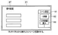
- the scene setting screen 61 for setting a scene which is a scene selection function, is displayed on a part of the operation panel device 21.
- the scene setting screen 61 may be displayed on another display device, for example, the operation panel device 21A.
- the scene setting screen 61 has a plurality of scene selection buttons 62, 63, 64, 65 for the surgeon to select a scene in surgery, and an operation button 66 for performing a scroll function, a page turning function, and the like.
- the state of each device can be collectively set by the person in charge of surgery by touching a desired button from the scene selection buttons 62, 63, 64, 65 according to the progress of the surgery.
- each device is a shadowless light 3, an interior light 7, a pneumoperitoneum device 14, a light source device 16, a display device 19, a recorder 17, and an electric knife device 13.
- the user can collectively set the status of each device described above, for example, on / off operation, execution / stop of various functions, output level setting, and the like.
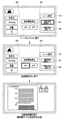
- 4A, 4B, 4C, 4D, and 4E are diagrams for explaining a setting screen when setting a scene.
- the system setting screen 70 includes a scene selection setting button 71 for setting a scene, a time setting button 72 for setting a time, and the like.
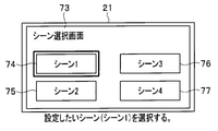
- the scene selection screen 73 shown in FIG. 4B is displayed on the operation panel device 21.
- the scene selection screen 73 has a plurality of scene setting buttons 74 to 77 for setting a scene.
- the scene setting button 74 is a button for setting the first scene (first scene)
- the scene setting button 75 is a button for setting the second scene
- the scene setting button 76 is 3. It is a button for setting the second scene
- the scene setting button 77 is a button for setting the fourth scene.
- the user wants to set a scene from the scene selection screen 73, for example, the first scene, the user touches the scene setting button 74 to display the scene setting screen 78 shown in FIG. 4C on the operation panel device 21.
- the user sets the name of the scene and each device using the scene setting screen 78.
- the scene setting screen 78 has a setting unit 79 in which the scene name is set, a setting unit 80 in which the order of the scenes is set, a setting unit 81 in which the device to be set is set, and a selection button 82 for changing the device to be set.
- the user inputs the scene name using the setting unit 79 of the scene setting screen 78 of FIG. 4C. "Preparation” is entered as the scene name.
- the order of the scenes corresponds to the selected scene. That is, when scene 1 is selected on the scene selection screen 73 of FIG. 4B, "1" is input to the setting unit 80 in which the order of the scenes is set, and when scene 2 is selected, the setting unit 80 is used. "2" is input.
- the device to be set is displayed in the setting unit 81.
- an interior light is displayed as a device to be set.
- the user uses the setting unit 83 to set ON / OFF of the interior light, the amount of light, and the like. Further, the user can set each device in the "preparation" scene by changing the device to be set by using the selection button 82.
- the control unit 41 communicates with the server / cloud 51 via the communication I / F 43, acquires the instruction manual and the video stored in the server / cloud 51, and the page number of the optimum instruction manual in each scene. , Determine and set the chapter of the video.
- a video of "handpiece assembly.wmv" is set as a material that the user wants to see, and a chapter of "assembly" of this video is set.
- the material to be set and the page number / chapter of the material are automatically input based on the conditions described later, but the user uses the selection buttons 85 and 87 to use the selection buttons 85 and 87 to use the material and the page number / chapter of the material. Can also be set manually.
- the scene setting screen 61 is displayed on the operation screen shown in FIG. 4D.
- the user can select a desired scene from the scene selection buttons 62, 63, ... On the scene setting screen 61.
- FIG. 5 is a diagram showing an example of setting contents of a scene related to a cholecystectomy procedure.
- the first scene is "1. Preparation”
- the second scene is "2. Endoscope insertion”
- the third scene is "3. Start using the handpiece”
- the last scene is "4". It is set to "End of surgery”.
- the interior light is set to OFF and the shadowless light is set to ON as the device settings.
- the chapter of "Assembly" of the video of "Assembly of Handpiece” is set.
- the timing for displaying (reproducing) the material is when the scene selection is executed, that is, when the scene of "1. Preparation” is set. In this embodiment, the timing of displaying (reproducing) the material is unified when the scene selection is executed.
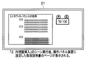
- page 70 of the instruction manual of the Video System Center is set as a document.
- the timing of displaying the material is the same as the scene of "1. Preparation" at the time of executing the scene selection.
- 6A, 6B, 6C and 6D are diagrams showing an example of a display screen at the time of scene selection.
- FIG. 7 is a diagram for explaining an example of search conditions for an instruction manual or a video that the user wants to see.
- the page numbers of the instruction manual and the chapter settings of the video are determined from the order of the scenes and the setting contents shown in the two search conditions A and B.
- the specific contents of the search conditions A and B are examples, and are not limited to the contents of FIG. 7. That is, the control unit 41 can also set the page number of the instruction manual and the chapter of the moving image according to the conditions other than the search conditions A and B shown in FIG.
- the search condition A is "a. Scene order" and / or "b. Scenes including specific device settings”.
- the search condition B is "a.
- the system controller stores the page number / video chapter of the material that the user has manually referred to in the past in a certain scene and reflects the content", "b.
- control unit 41 searches for "a. First scene to be executed” in search condition A and "a. Video of the handpiece assembly method referred to in the first scene to be executed in the past and its chapters" in search condition B. Then, set the information that the user wants to see based on "Set the search result in the scene”. As a result, the chapter name of the video of handpiece assembly is set to "assembly".
- the display page of the "Video System Center Instruction Manual” is set to "Page 70", and in the third scene, the chapter of the video "How to use the handpiece".
- the name is set to "How to use”
- the display page of "How to clean up the equipment and the instruction manual of the storage location” is set to "Page 120".
- FIG. 8 is a flowchart showing the flow of processing at the time of setting the material in the scene of "1. Preparation”.
- the control unit 41 determines whether or not the first scene to be executed (scene number 1) has been edited (S1). When the control unit 41 determines that the scene to be executed first (scene number 1) has not been edited, the control unit 41 executes another process (S2). After executing other processes, the control unit 41 may return to the process at the beginning of the flowchart, or may end the process of the flowchart.
- control unit 41 determines that the scene to be executed first (scene number 1) has been edited, the control unit 41 obtains the information of the moving images and chapters referred to in the scene first executed from the past predetermined number of cases from the history. Call (S3).
- control unit 41 determines the most referenced video / chapter from the call history (S4).
- the control unit 41 sets the moving image / chapter most referenced from the discrimination result in the scene (S5), and ends the process.
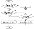
- FIG. 9 is a flowchart showing the flow of processing at the time of scene selection in the scene of "1. Preparation”.
- the control unit 41 determines whether or not the scene of the scene number 1 has been executed (S11). When the control unit 41 determines that the scene of the scene number 1 has not been executed, the control unit 41 executes another process (S12). After executing other processes, the control unit 41 may return to the process at the beginning of the flowchart, or may end the process of the flowchart.
- the control unit 41 determines whether or not the set moving image / chapter is the most referenced (S13). That is, in the process of FIG. 8, the control unit 41 determines the most referenced video / chapter and sets the video / chapter as the scene, but when the scene selection is actually executed, one It is possible that the video / chapter that was referenced is no longer the video / chapter that was most referenced. Therefore, the control unit 41 determines whether or not the set moving image / chapter is the most referenced.
- control unit 41 determines that the set video / chapter is the most referenced
- the control unit 41 plays the set video / chapter (S14) and ends the process.
- the control unit 41 determines whether or not to play the most referenced moving image / chapter (S15).
- control unit 41 determines that the most referenced video / chapter is not played, the control unit 41 proceeds to the process of S14, plays the set video / chapter (S14), and ends the process.
- the control unit 41 determines that the most referenced moving image / chapter is to be reproduced, the most referenced moving image / chapter is reproduced (S16), and the process is terminated.
- FIG. 10 is a flowchart showing the flow of processing at the time of setting the material in the scene of "3. Start of using the handpiece".
- the control unit 41 determines whether or not the scene including the output value of the electric knife has been edited (S21). When the control unit 41 determines that the scene including the output value of the electric knife has not been edited, the control unit 41 executes another process (S22). After executing other processes, the control unit 41 may return to the process at the beginning of the flowchart, or may end the process of the flowchart.
- control unit 41 determines that the scene including the output value of the electric knife has been edited, the control unit 41 determines the handpiece to be used from the procedure name "cholecystectomy" and the device (electric knife) used in this scene. (S23).
- the control unit 41 determines whether or not the scene number is the smallest among the scenes in which the output of the electric knife is set (S24). When the control unit 41 determines that the scene number is not the smallest number among the scenes in which the output of the electric knife is set, the control unit 41 executes another process (S25). After executing other processes, the control unit 41 may return to the process at the beginning of the flowchart, or may end the process of the flowchart.
- control unit 41 determines that the scene number is the smallest number among the scenes in which the output of the electric knife is set, the control unit 41 determines a moving image / chapter of how to use the handpiece and sets it in the scene. (S26), the process is terminated.
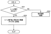
- FIG. 11 is a flowchart showing the flow of processing at the time of scene selection in the scene of "3. Start of using the handpiece".
- the control unit 41 determines whether or not the scene has been executed (S31). In the process of S31, the control unit 41 determines whether or not the scene of "3. Start of use of the handpiece" has been executed. When the control unit 41 determines that the scene has not been executed, the control unit 41 executes another process (S32). After executing other processes, the control unit 41 may return to the process at the beginning of the flowchart, or may end the process of the flowchart.
- control unit 41 determines that the scene has been executed, the control unit 41 plays the set moving image / chapter after executing the scene (S33), and ends the process. As a result, the control unit 41 reproduces the chapter of the "how to use” of the video of the set "how to use the handpiece” in the scene of "3. start of using the handpiece".
- control unit 41 of the system controller 22 determines the most suitable material for the scene, here, the page number of the instruction manual, or the chapter of the video from the order of the scenes and the setting contents at the time of setting the scene. Set.
- the control unit 41 collectively sets each device, displays the corresponding page of the instruction manual, or reproduces from the corresponding chapter of the moving image.
- control unit 41 displays the material and reproduces the moving image at the set timing, so that it is possible to display only the necessary information at an appropriate timing according to each scene. , The user can proceed with the work efficiently.
- the centralized control device of the present embodiment information on the work to be performed according to the progress of the surgery can be displayed in a timely manner according to the progress of the surgery.
- the control unit 41 can help the work that occurs in the progress of the surgery, and can lead to the efficiency of the surgery performed by the user.
- the search conditions for information related to the work performed according to the progress of the surgery are not limited to the search conditions A and B in FIG. 7, and other search conditions can also be applied.
- the page number of the instruction manual or the timing of playing the chapter of the moving image is limited to the time when the scene selection is executed.
- the page number of the instruction manual can be displayed, or the timing for playing the chapter of the moving image can be set.
- FIG. 12 is a diagram for explaining a setting screen when setting a scene.
- the same components as those in FIG. 4C are designated by the same reference numerals and the description thereof will be omitted.
- the scene setting screen 78A includes a setting unit 88 for setting the timing for displaying page numbers / chapters of materials (instruction manuals and moving images) and selection in addition to the configuration of the scene setting screen 78 in FIG. 4C. It is equipped with a button 89.
- the user can set the display / playback timing of the material (instruction manual or video) by touching the selection button 89.
- “press the air supply start button” is set in the setting unit 88 as the display / playback timing, and when the user presses the air supply start button of the pneumoperitoneum device 14, the pneumoperitoneum device Page 70 of the instruction manual will be displayed.
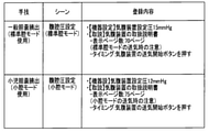
- FIG. 13 is a diagram showing an example of registration contents set for each procedure and scene.
- the set pressure of the pneumoperitoneum device is set to 15 mmHg as the device setting, and the instruction manual of the pneumoperitoneum device is used as a reference.
- Page 70 is set, and pressing the air supply start button of the pneumoperitoneum device is set as the display timing of the material.
- the set pressure of the pneumoperitoneum device is set to 12 mmHg as the device setting, and page 75 of the instruction manual of the pneumoperitoneum device is set as a document. , Press the air supply start button of the pneumoperitoneum device as the display timing of the material.
- FIG. 14 is a diagram showing an example of a screen display when a scene of abdominal pressure setting (standard cavity mode) is selected
- FIG. 15 is a diagram showing an example of a screen display when a scene of abdominal pressure setting (small cavity mode) is selected. It is a figure which shows an example of a screen display.
- the scene setting screen 61 has a scene selection button 91 for selecting a scene for abdominal pressure setting (standard cavity mode) and a scene for selecting a scene for abdominal pressure setting (small cavity mode). It has a selection button 92.
- the device is set by the user pressing the scene selection button 91 for selecting the scene of the abdominal pressure setting (standard cavity mode).
- the set pressure of the pneumoperitoneum device is set to 15 mmHg.
- the device setting screen includes an air supply start button 93 for starting air supply and an air supply stop button 94 for stopping air supply.
- control unit 41 displays page 70 of the instruction manual in which the precautions for air supply in the standard cavity mode are described according to the display timing of the set material. ..
- the device is set by pressing the scene selection button 92 for the user to select the scene of the abdominal pressure setting (small cavity mode).
- the set pressure of the pneumoperitoneum device is set to 12 mmHg.
- the control unit 41 displays page 75 of the instruction manual in which the precautions for air supply in the small cavity mode are described according to the display timing of the set material. indicate.
- FIG. 16 is a diagram showing search conditions for the set material.
- the set pressure of the pneumoperitoneum device is set to 15 mmHg, and the standard cavity mode is determined from the procedure name and this set pressure.
- page 70 which is a page number in which cautions for air supply in the standard cavity mode are described, is set in the scene.
- the set pressure of the pneumoperitoneum device is set to 12 mmHg, and it is determined from the procedure name and this set pressure that it is in the small cavity mode.
- page 75 which is a page number in which cautions for air supply in the small cavity mode are described, is set in the scene.
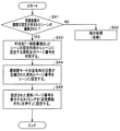
- FIG. 17 is a flowchart showing the flow of processing at the time of setting the material in the scene of the abdominal pressure setting (standard cavity mode).
- the control unit 41 determines whether or not the scene including the abdominal pressure setting of the pneumoperitoneum device has been edited (S41). When the control unit 41 determines that the scene including the abdominal pressure setting of the pneumoperitoneum device has not been edited, the control unit 41 executes another process (S42). After executing other processes, the control unit 41 may return to the process at the beginning of the flowchart, or may end the process of the flowchart.
- control unit 41 determines that the scene including the abdominal pressure setting of the pneumoperitoneum device has been edited, the control unit 41 determines the procedure name "general cholecystectomy" and the material and page number to be set in the scene from the setting contents of the scene. Discrimination (S43). The control unit 41 determines, for example, from the set pressure of the pneumoperitoneum device, the instruction manual of the pneumoperitoneum device and the page number in which the precautions for insufflation in the standard cavity mode are described.
- the control unit 41 sets the material and the page number in which the precautions for insufflation in the standard cavity mode determined in the process of S43 are described in the scene (S44). Finally, the control unit 41 sets the timing for displaying the set material and the page number to "press the air supply start button" (S45), and ends the process.
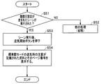
- FIG. 18 is a flowchart showing the flow of processing at the time of scene selection in the scene of the abdominal pressure setting (standard cavity mode).
- the control unit 41 determines whether or not the scene including the abdominal pressure setting has been executed (S51). When the control unit 41 determines that the scene including the abdominal pressure setting is not executed, the control unit 41 executes another process (S52). After executing other processes, the control unit 41 may return to the process at the beginning of the flowchart, or may end the process of the flowchart.
- control unit 41 determines that the scene including the abdominal pressure setting has been executed and the air supply start button is pressed after the scene execution (S53), the control unit 41 pays attention to the air supply in the standard cavity mode.
- the described material and page number are displayed (S54), and the process is terminated.
- control unit 41 of the system controller 22 can confirm the necessary information at the timing desired by the user by setting the page number of the instruction manual and the timing of playing the video in the scene selection. , You can check the precautions according to the progress of the surgery.
- the user can check the necessary information at the timing he wants to see, check the precautions according to the progress of the surgery, and troubles. You can take corrective action quickly.
- the error when an error occurs in a device during a procedure, the error can be resolved immediately by displaying a document or a moving image that describes how to deal with the error.
- FIG. 19 is a diagram for explaining a setting screen when setting a scene.
- the scene setting image 78B surface of FIG. 19 has the same screen configuration as the scene setting screen 78A of FIG.
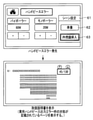
- page 40 of the instruction manual of the electric knife is set as a document, and the time when a handpiece error occurs is set as the timing.
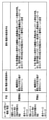
- FIG. 20 is a diagram showing an example of registration contents set for each procedure and scene.
- the registration contents set for each procedure and scene when the procedure is cholecystectomy and the scene is endoscopic insertion, the measures to be taken when the output value of the handpiece for the gallbladder error is described according to the output value (80W) of the electric knife.
- Page 40 of the instruction manual of the electric knife is set, and the display timing is set when the electric knife handpiece error occurs.
- 21 and 22 are diagrams for explaining an example of a display screen when a handpiece error occurs.
- FIG. 23 is a diagram showing the search conditions for the set material.
- the control unit 41 discriminates the handpiece material for cholecystectomy from the scene in which the output value of the electric knife is included in the device setting, the procedure (cholecystectomy), and the device used. Further, the control unit 41 sets a page number in the scene, which describes how to deal with the cholecystectomy handpiece output error from the setting contents (when a handpiece error occurs).
- control unit 41 discriminates the handpiece material for gastric removal from the scene in which the output value of the electric knife is included in the device setting and the device used for the procedure (gastric removal). Further, the control unit 41 sets a page number in the scene, which describes how to deal with the gastric removal handpiece output error from the setting contents (when a handpiece error occurs).
- FIG. 24 is a flowchart showing the flow of processing at the time of setting the material in the scene of endoscopic insertion of the cholecystectomy procedure.
- the control unit 41 determines whether or not the scene including the output value of the electric knife has been edited (S61). When the control unit 41 determines that the scene including the output value of the electric knife has not been edited, the control unit 41 executes another process (S62). After executing other processes, the control unit 41 may return to the process at the beginning of the flowchart, or may end the process of the flowchart.
- control unit 41 determines that the scene including the output value of the electric knife has been edited, the control unit 41 determines the handpiece to be used from the procedure name "cholecystectomy" and the device (electric knife) used in this scene. (S63).
- the control unit 41 sets the timing for displaying the material / page number in "when an electric knife handpiece error occurs" (S64).
- the control unit 41 sets the material / page number in which the countermeasures for the gallbladder handpiece output error are described from the set contents in the scene (S65), and ends the process.
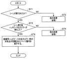
- FIG. 25 is a flowchart showing the flow of processing at the time of scene selection in the scene of endoscopic insertion of the cholecystectomy procedure.
- the control unit 41 determines whether or not the scene has been executed (S71). If the control unit 41 determines that the scene has not been executed, the control unit 41 executes another process (S72). After executing other processes, the control unit 41 may return to the process at the beginning of the flowchart, or may end the process of the flowchart.
- control unit 41 determines whether or not a handpiece error has occurred after the scene is executed (S73). If the control unit 41 determines that no handpiece error has occurred after executing the scene, the control unit 41 executes another process (S74). After executing other processes, the control unit 41 may return to the process at the beginning of the flowchart, or may end the process of the flowchart.
- control unit 41 determines that a handpiece error has occurred after executing the scene, the control unit 41 displays a page number describing a countermeasure for an output error of the cholecystectomy handpiece (S75), and ends the process. do.
- control unit 41 of the system controller 22 sets the page number of the instruction manual and the timing of playing the video in the scene selection when an error occurs, so that the user confirms the necessary information at the timing desired to be viewed. It is possible to quickly deal with troubles according to the progress of surgery.
- each step in the flowchart in the present specification may be executed at the same time by changing the execution order, or may be executed in a different order for each execution, as long as it does not violate the nature of the steps.
- the present invention is not limited to the above-described embodiment, and various changes, modifications, and the like can be made without changing the gist of the present invention.
Landscapes
- Health & Medical Sciences (AREA)
- Engineering & Computer Science (AREA)
- Surgery (AREA)
- Life Sciences & Earth Sciences (AREA)
- Public Health (AREA)
- General Health & Medical Sciences (AREA)
- Medical Informatics (AREA)
- Biomedical Technology (AREA)
- Nuclear Medicine, Radiotherapy & Molecular Imaging (AREA)
- Veterinary Medicine (AREA)
- Animal Behavior & Ethology (AREA)
- Heart & Thoracic Surgery (AREA)
- Molecular Biology (AREA)
- Pathology (AREA)
- Oral & Maxillofacial Surgery (AREA)
- Primary Health Care (AREA)
- Epidemiology (AREA)
- Robotics (AREA)
- Human Computer Interaction (AREA)
- Gynecology & Obstetrics (AREA)
- Radiology & Medical Imaging (AREA)
- Business, Economics & Management (AREA)
- General Business, Economics & Management (AREA)
- Bioethics (AREA)
- Anesthesiology (AREA)
- Hematology (AREA)
- Urology & Nephrology (AREA)
- Endoscopes (AREA)
Abstract
Le dispositif de commande centralisée selon la présente invention commande un appareil à commander, et comprend : une unité d'interface de communication d'appareil qui communique avec l'appareil à commander ; une unité de détermination qui, dans une pluralité de scènes définies en fonction de la progression d'une chirurgie prédéterminée, détermine des informations relatives à une chirurgie optimale requises pour une procédure relative à la chirurgie prédéterminée en fonction de chacune de la pluralité de scènes ; une unité d'enregistrement qui enregistre un nom de scène correspondant à chacune de la pluralité de scènes définies en fonction de la progression de la chirurgie prédéterminée, une valeur de consigne de l'appareil à commander, et les informations relatives à une chirurgie optimale déterminées par l'unité de détermination en association les unes avec les autres ; et une unité de commande qui commande l'affichage des informations relatives à une chirurgie optimale enregistrées dans l'unité d'enregistrement, lorsqu'une scène prédéterminée est définie parmi la pluralité de scènes.
Priority Applications (2)
| Application Number | Priority Date | Filing Date | Title |
|---|---|---|---|
| PCT/JP2020/027693 WO2022014014A1 (fr) | 2020-07-16 | 2020-07-16 | Dispositif de commande centralisée et procédé d'affichage d'informations relatives à une chirurgie |
| US18/096,070 US20230149100A1 (en) | 2020-07-16 | 2023-01-12 | Control apparatus, medical central control system, and surgery-related information display method |
Applications Claiming Priority (1)
| Application Number | Priority Date | Filing Date | Title |
|---|---|---|---|
| PCT/JP2020/027693 WO2022014014A1 (fr) | 2020-07-16 | 2020-07-16 | Dispositif de commande centralisée et procédé d'affichage d'informations relatives à une chirurgie |
Related Child Applications (1)
| Application Number | Title | Priority Date | Filing Date |
|---|---|---|---|
| US18/096,070 Continuation US20230149100A1 (en) | 2020-07-16 | 2023-01-12 | Control apparatus, medical central control system, and surgery-related information display method |
Publications (1)
| Publication Number | Publication Date |
|---|---|
| WO2022014014A1 true WO2022014014A1 (fr) | 2022-01-20 |
Family
ID=79554576
Family Applications (1)
| Application Number | Title | Priority Date | Filing Date |
|---|---|---|---|
| PCT/JP2020/027693 Ceased WO2022014014A1 (fr) | 2020-07-16 | 2020-07-16 | Dispositif de commande centralisée et procédé d'affichage d'informations relatives à une chirurgie |
Country Status (2)
| Country | Link |
|---|---|
| US (1) | US20230149100A1 (fr) |
| WO (1) | WO2022014014A1 (fr) |
Citations (7)
| Publication number | Priority date | Publication date | Assignee | Title |
|---|---|---|---|---|
| JPH07132121A (ja) * | 1993-11-09 | 1995-05-23 | Olympus Optical Co Ltd | 医療用制御システム |
| JP2003284690A (ja) * | 2002-03-28 | 2003-10-07 | Nippon Telegr & Teleph Corp <Ntt> | 比較読影支援方法、比較読影支援装置、比較読影支援プログラム及びそのプログラムを記録した記録媒体 |
| US20070174090A1 (en) * | 2006-01-26 | 2007-07-26 | International Business Machines Corporation | Methods, systems and computer program products for synthesizing medical procedure information in healthcare databases |
| JP2015197757A (ja) * | 2014-03-31 | 2015-11-09 | 株式会社ホギメディカル | 手術用情報処理システム及び手術用情報処理プログラム |
| US20190090954A1 (en) * | 2017-09-28 | 2019-03-28 | General Electric Company | Workflow assistant for image guided procedures |
| WO2019111512A1 (fr) * | 2017-12-05 | 2019-06-13 | ソニー・オリンパスメディカルソリューションズ株式会社 | Dispositif de traitement d'informations médicales et procédé de traitement d'informations |
| JP2019185726A (ja) * | 2018-10-25 | 2019-10-24 | 株式会社ミルプラトー | 動画閲覧装置、動画閲覧装置の制御方法、およびプログラム |
-
2020
- 2020-07-16 WO PCT/JP2020/027693 patent/WO2022014014A1/fr not_active Ceased
-
2023
- 2023-01-12 US US18/096,070 patent/US20230149100A1/en active Pending
Patent Citations (7)
| Publication number | Priority date | Publication date | Assignee | Title |
|---|---|---|---|---|
| JPH07132121A (ja) * | 1993-11-09 | 1995-05-23 | Olympus Optical Co Ltd | 医療用制御システム |
| JP2003284690A (ja) * | 2002-03-28 | 2003-10-07 | Nippon Telegr & Teleph Corp <Ntt> | 比較読影支援方法、比較読影支援装置、比較読影支援プログラム及びそのプログラムを記録した記録媒体 |
| US20070174090A1 (en) * | 2006-01-26 | 2007-07-26 | International Business Machines Corporation | Methods, systems and computer program products for synthesizing medical procedure information in healthcare databases |
| JP2015197757A (ja) * | 2014-03-31 | 2015-11-09 | 株式会社ホギメディカル | 手術用情報処理システム及び手術用情報処理プログラム |
| US20190090954A1 (en) * | 2017-09-28 | 2019-03-28 | General Electric Company | Workflow assistant for image guided procedures |
| WO2019111512A1 (fr) * | 2017-12-05 | 2019-06-13 | ソニー・オリンパスメディカルソリューションズ株式会社 | Dispositif de traitement d'informations médicales et procédé de traitement d'informations |
| JP2019185726A (ja) * | 2018-10-25 | 2019-10-24 | 株式会社ミルプラトー | 動画閲覧装置、動画閲覧装置の制御方法、およびプログラム |
Also Published As
| Publication number | Publication date |
|---|---|
| US20230149100A1 (en) | 2023-05-18 |
Similar Documents
| Publication | Publication Date | Title |
|---|---|---|
| JP4681908B2 (ja) | 手術機器コントローラ及びそれを用いた手術システム | |
| JP4813349B2 (ja) | 内視鏡システム | |
| EP1870827B1 (fr) | Système de commande de l'enregistrement d'images d'une opération technique, sa méthode et son système opératif | |
| JP2006000536A (ja) | 手術室制御システム | |
| US20060287645A1 (en) | System and controller for controlling operating room | |
| JP5945644B1 (ja) | 医療システム | |
| JP2006223375A (ja) | 手術データ記録装置、手術データ表示装置及び手術データ記録表示方法 | |
| JP2006081664A (ja) | 医療用システム、医療用システムの制御方法 | |
| JP2006000538A (ja) | 手術室制御システム | |
| US20180092509A1 (en) | Image recording device | |
| JP6901590B2 (ja) | 集中制御装置及び医療機器を含む1又は2以上の被制御装置を制御する集中制御装置の作動方法 | |
| US10973593B2 (en) | Centralized control apparatus | |
| JP5750641B2 (ja) | 医療支援装置及び医療支援装置の作動方法 | |
| US11648065B2 (en) | Centralized control apparatus and instrument operation method | |
| JP6374263B2 (ja) | 医療システム | |
| WO2022014014A1 (fr) | Dispositif de commande centralisée et procédé d'affichage d'informations relatives à une chirurgie | |
| CN112640442B (zh) | 图像记录再现装置、图像记录方法和内窥镜系统 | |
| JP2006000537A (ja) | 内視鏡システム | |
| JP7451707B2 (ja) | 制御装置、データログの表示方法及び医療用集中制御システム | |
| JP2007082630A (ja) | 統合手術室制御システム | |
| JP2007068562A (ja) | 医療機器用電源制御装置及び手術室制御システム | |
| JP2003175043A (ja) | 医療用制御装置 | |
| JP2006218236A (ja) | 手術制御システム | |
| JP2007068565A (ja) | 手術室制御システム及び非医療機器コントローラ | |
| JP2008023126A (ja) | 手術制御システム |
Legal Events
| Date | Code | Title | Description |
|---|---|---|---|
| 121 | Ep: the epo has been informed by wipo that ep was designated in this application |
Ref document number: 20945163 Country of ref document: EP Kind code of ref document: A1 |
|
| NENP | Non-entry into the national phase |
Ref country code: DE |
|
| 122 | Ep: pct application non-entry in european phase |
Ref document number: 20945163 Country of ref document: EP Kind code of ref document: A1 |
|
| NENP | Non-entry into the national phase |
Ref country code: JP |