WO2022014109A1 - インナーリング、及び管継手 - Google Patents
インナーリング、及び管継手 Download PDFInfo
- Publication number
- WO2022014109A1 WO2022014109A1 PCT/JP2021/014020 JP2021014020W WO2022014109A1 WO 2022014109 A1 WO2022014109 A1 WO 2022014109A1 JP 2021014020 W JP2021014020 W JP 2021014020W WO 2022014109 A1 WO2022014109 A1 WO 2022014109A1
- Authority
- WO
- WIPO (PCT)
- Prior art keywords
- axial direction
- inner ring
- outer end
- diameter
- bulging portion
- Prior art date
- Legal status (The legal status is an assumption and is not a legal conclusion. Google has not performed a legal analysis and makes no representation as to the accuracy of the status listed.)
- Ceased
Links
Images

Classifications
-
- F—MECHANICAL ENGINEERING; LIGHTING; HEATING; WEAPONS; BLASTING
- F16—ENGINEERING ELEMENTS AND UNITS; GENERAL MEASURES FOR PRODUCING AND MAINTAINING EFFECTIVE FUNCTIONING OF MACHINES OR INSTALLATIONS; THERMAL INSULATION IN GENERAL
- F16L—PIPES; JOINTS OR FITTINGS FOR PIPES; SUPPORTS FOR PIPES, CABLES OR PROTECTIVE TUBING; MEANS FOR THERMAL INSULATION IN GENERAL
- F16L47/00—Connecting arrangements or other fittings specially adapted to be made of plastics or to be used with pipes made of plastics
- F16L47/04—Connecting arrangements or other fittings specially adapted to be made of plastics or to be used with pipes made of plastics with a swivel nut or collar engaging the pipe
-
- F—MECHANICAL ENGINEERING; LIGHTING; HEATING; WEAPONS; BLASTING
- F16—ENGINEERING ELEMENTS AND UNITS; GENERAL MEASURES FOR PRODUCING AND MAINTAINING EFFECTIVE FUNCTIONING OF MACHINES OR INSTALLATIONS; THERMAL INSULATION IN GENERAL
- F16L—PIPES; JOINTS OR FITTINGS FOR PIPES; SUPPORTS FOR PIPES, CABLES OR PROTECTIVE TUBING; MEANS FOR THERMAL INSULATION IN GENERAL
- F16L33/00—Arrangements for connecting hoses to rigid members; Rigid hose-connectors, i.e. single members engaging both hoses
- F16L33/22—Arrangements for connecting hoses to rigid members; Rigid hose-connectors, i.e. single members engaging both hoses with means not mentioned in the preceding groups for gripping the hose between inner and outer parts
- F16L33/222—Arrangements for connecting hoses to rigid members; Rigid hose-connectors, i.e. single members engaging both hoses with means not mentioned in the preceding groups for gripping the hose between inner and outer parts the external piece comprising segments pressed against the hose by wedge shaped elements
-
- F—MECHANICAL ENGINEERING; LIGHTING; HEATING; WEAPONS; BLASTING
- F16—ENGINEERING ELEMENTS AND UNITS; GENERAL MEASURES FOR PRODUCING AND MAINTAINING EFFECTIVE FUNCTIONING OF MACHINES OR INSTALLATIONS; THERMAL INSULATION IN GENERAL
- F16L—PIPES; JOINTS OR FITTINGS FOR PIPES; SUPPORTS FOR PIPES, CABLES OR PROTECTIVE TUBING; MEANS FOR THERMAL INSULATION IN GENERAL
- F16L19/00—Joints in which sealing surfaces are pressed together by means of a member, e.g. a swivel nut, screwed on, or into, one of the joint parts
- F16L19/04—Joints in which sealing surfaces are pressed together by means of a member, e.g. a swivel nut, screwed on, or into, one of the joint parts using additional rigid rings, sealing directly on at least one pipe end, which is flared either before or during the making of the connection
-
- F—MECHANICAL ENGINEERING; LIGHTING; HEATING; WEAPONS; BLASTING
- F16—ENGINEERING ELEMENTS AND UNITS; GENERAL MEASURES FOR PRODUCING AND MAINTAINING EFFECTIVE FUNCTIONING OF MACHINES OR INSTALLATIONS; THERMAL INSULATION IN GENERAL
- F16L—PIPES; JOINTS OR FITTINGS FOR PIPES; SUPPORTS FOR PIPES, CABLES OR PROTECTIVE TUBING; MEANS FOR THERMAL INSULATION IN GENERAL
- F16L33/00—Arrangements for connecting hoses to rigid members; Rigid hose-connectors, i.e. single members engaging both hoses
- F16L33/22—Arrangements for connecting hoses to rigid members; Rigid hose-connectors, i.e. single members engaging both hoses with means not mentioned in the preceding groups for gripping the hose between inner and outer parts
-
- F—MECHANICAL ENGINEERING; LIGHTING; HEATING; WEAPONS; BLASTING
- F16—ENGINEERING ELEMENTS AND UNITS; GENERAL MEASURES FOR PRODUCING AND MAINTAINING EFFECTIVE FUNCTIONING OF MACHINES OR INSTALLATIONS; THERMAL INSULATION IN GENERAL
- F16L—PIPES; JOINTS OR FITTINGS FOR PIPES; SUPPORTS FOR PIPES, CABLES OR PROTECTIVE TUBING; MEANS FOR THERMAL INSULATION IN GENERAL
- F16L33/00—Arrangements for connecting hoses to rigid members; Rigid hose-connectors, i.e. single members engaging both hoses
- F16L33/22—Arrangements for connecting hoses to rigid members; Rigid hose-connectors, i.e. single members engaging both hoses with means not mentioned in the preceding groups for gripping the hose between inner and outer parts
- F16L33/223—Arrangements for connecting hoses to rigid members; Rigid hose-connectors, i.e. single members engaging both hoses with means not mentioned in the preceding groups for gripping the hose between inner and outer parts the sealing surfaces being pressed together by means of a member, e.g. a swivel nut, screwed on or into one of the joint parts
-
- F—MECHANICAL ENGINEERING; LIGHTING; HEATING; WEAPONS; BLASTING
- F16—ENGINEERING ELEMENTS AND UNITS; GENERAL MEASURES FOR PRODUCING AND MAINTAINING EFFECTIVE FUNCTIONING OF MACHINES OR INSTALLATIONS; THERMAL INSULATION IN GENERAL
- F16L—PIPES; JOINTS OR FITTINGS FOR PIPES; SUPPORTS FOR PIPES, CABLES OR PROTECTIVE TUBING; MEANS FOR THERMAL INSULATION IN GENERAL
- F16L47/00—Connecting arrangements or other fittings specially adapted to be made of plastics or to be used with pipes made of plastics
- F16L47/04—Connecting arrangements or other fittings specially adapted to be made of plastics or to be used with pipes made of plastics with a swivel nut or collar engaging the pipe
- F16L47/041—Connecting arrangements or other fittings specially adapted to be made of plastics or to be used with pipes made of plastics with a swivel nut or collar engaging the pipe the plastic pipe end being flared either before or during the making of the connection
-
- F—MECHANICAL ENGINEERING; LIGHTING; HEATING; WEAPONS; BLASTING
- F16—ENGINEERING ELEMENTS AND UNITS; GENERAL MEASURES FOR PRODUCING AND MAINTAINING EFFECTIVE FUNCTIONING OF MACHINES OR INSTALLATIONS; THERMAL INSULATION IN GENERAL
- F16L—PIPES; JOINTS OR FITTINGS FOR PIPES; SUPPORTS FOR PIPES, CABLES OR PROTECTIVE TUBING; MEANS FOR THERMAL INSULATION IN GENERAL
- F16L19/00—Joints in which sealing surfaces are pressed together by means of a member, e.g. a swivel nut, screwed on, or into, one of the joint parts
- F16L19/04—Joints in which sealing surfaces are pressed together by means of a member, e.g. a swivel nut, screwed on, or into, one of the joint parts using additional rigid rings, sealing directly on at least one pipe end, which is flared either before or during the making of the connection
- F16L19/041—Joints in which sealing surfaces are pressed together by means of a member, e.g. a swivel nut, screwed on, or into, one of the joint parts using additional rigid rings, sealing directly on at least one pipe end, which is flared either before or during the making of the connection the ring being an insert
-
- F—MECHANICAL ENGINEERING; LIGHTING; HEATING; WEAPONS; BLASTING
- F16—ENGINEERING ELEMENTS AND UNITS; GENERAL MEASURES FOR PRODUCING AND MAINTAINING EFFECTIVE FUNCTIONING OF MACHINES OR INSTALLATIONS; THERMAL INSULATION IN GENERAL
- F16L—PIPES; JOINTS OR FITTINGS FOR PIPES; SUPPORTS FOR PIPES, CABLES OR PROTECTIVE TUBING; MEANS FOR THERMAL INSULATION IN GENERAL
- F16L19/00—Joints in which sealing surfaces are pressed together by means of a member, e.g. a swivel nut, screwed on, or into, one of the joint parts
- F16L19/06—Joints in which sealing surfaces are pressed together by means of a member, e.g. a swivel nut, screwed on, or into, one of the joint parts in which radial clamping is obtained by wedging action on non-deformed pipe ends
- F16L19/07—Joints in which sealing surfaces are pressed together by means of a member, e.g. a swivel nut, screwed on, or into, one of the joint parts in which radial clamping is obtained by wedging action on non-deformed pipe ends adapted for use in socket or sleeve connections
Definitions
- the present invention relates to an inner ring and a pipe joint.
- a pipe joint made of synthetic resin As such a pipe joint, an inner ring attached to the inner peripheral side of the tip of the tube, a cylindrical joint body attached to the outer peripheral side of the tip of the tube, and an outer ring of the joint body are attached.
- Those provided with a union nut are known (see, for example, Patent Document 1).
- the inner ring has a cylindrical main body portion, a bulging portion formed by projecting outward in diameter at one end portion in the axial direction of the main body portion, and a sealing portion formed at the other end portion in the axial direction of the main body portion. is doing.
- a fluid flow path is formed inside the inner ring.
- the bulging portion of the inner ring is press-fitted into the tip portion of the tube to expand the diameter of the tip portion of the tube.
- the union nut is attached to the joint body and presses the outer peripheral surface of the tube whose diameter has been expanded by the bulging portion of the inner ring. As a result, the seal portion of the inner ring is pressed against the seal groove formed in the joint body.
- the cross-sectional shape of the bulging portion in the inner ring is formed so as to gradually taper from the central portion in the axial direction toward the outer end in the axial direction, and the outer end in the axial direction of the bulging portion is formed sharply.
- the radial thickness of the bulge is the thinnest at the outer end in the axial direction. Therefore, when the union nut presses the enlarged diameter portion of the tube, the axially outer end portion of the bulging portion may be deformed so as to collapse (jump out) inward in diameter (fluid flow path side) due to insufficient strength. be.
- the present invention has been made in view of such circumstances, and an object of the present invention is to provide an inner ring and a pipe joint capable of suppressing the axial outer end portion of a bulging portion from collapsing inward in diameter. ..
- the inner ring of the present invention is formed by projecting outward in diameter at the outer end portion in the axial direction, has a bulging portion that is press-fitted into the tip portion of the tube, and has a fluid flow path inside the diameter of the bulging portion.
- the formed inner ring, the bulging portion is formed so as to taper from the inner side in the axial direction toward the outer end in the axial direction in a cross-sectional view in the axial direction, and is formed at the outer end in the axial direction. It has a flat surface extending in the radial direction.
- the bulging portion formed so as to taper from the inner side in the axial direction toward the outer end in the axial direction has a flat surface extending in the radial direction formed at the outer end in the axial direction.
- the radial thickness at the axial outer end of the bulge can be made thicker than before.
- the strength at the axially outer end of the bulge is higher than before, so even if the tube is pressed by the union nut while the bulge is pressed into the tip of the tube, the shaft of the bulge It is possible to prevent the outer end of the direction from collapsing inward in the diameter (toward the fluid flow path).
- the surface pressure between the contact surfaces of the axially outer end of the bulging portion and the tube becomes higher than in the conventional case, so that it is possible to suppress the infiltration of fluid between these contact surfaces.
- the bulging portion has a tapered surface whose inner peripheral surface is inclined so as to gradually increase in diameter from the inner side in the axial direction toward the outer end in the axial direction. In this case, even if the bulging portion collapses inward when the union nut presses the tube, it is possible to prevent the inner peripheral surface of the bulging portion from protruding inward in diameter. As a result, it is possible to prevent the flow of fluid in the fluid flow path of the inner ring from being obstructed by the inner peripheral surface of the bulging portion.
- the bulging portion preferably has a chamfered portion formed at a corner portion formed by the tapered surface and the flat surface. In this case, even if the fluid enters the recess formed between the corner portion of the bulging portion and the tube, the fluid in the recess easily flows to the fluid flow path side by the chamfered portion, so that the fluid enters the recess. Can be suppressed from remaining.
- the radial thickness dimension at the axial outer end of the bulging portion is preferably 3% or more and 30% or less with respect to the maximum radial thickness dimension of the bulging portion.
- the axial outer end of the bulge is formed. Further increase in strength.
- the surface pressure between the contact surfaces of the outer end portion in the axial direction of the bulging portion and the tube is further increased, so that it is possible to effectively suppress the infiltration of fluid between these contact surfaces.
- the axial outer end portion of the bulging portion has a diameter. It is possible to further suppress the inner peripheral surface of the bulging portion from protruding inward in diameter when it falls inward. As a result, it is possible to effectively suppress the flow of fluid in the fluid flow path of the inner ring from being obstructed by the inner peripheral surface of the bulging portion.
- the pipe joint of the present invention includes a joint body having a male threaded portion formed on the outer periphery, a union nut having a female threaded portion tightened to the male threaded portion formed on the inner circumference, and the above (1) to (4).
- the inner ring described in any of them is provided.
- the bulging portion formed so as to taper from the inner side in the axial direction toward the outer end in the axial direction is a flat surface extending in the radial direction formed at the outer end in the axial direction. Therefore, the thickness in the radial direction at the axial outer end of the bulging portion can be made thicker than before.
- the strength at the axially outer end of the bulge is higher than before, so even if the tube is pressed by the union nut while the bulge is pressed into the tip of the tube, the shaft of the bulge It is possible to prevent the outer end of the direction from collapsing inward in the diameter (toward the fluid flow path).
- the surface pressure between the contact surfaces of the outer end portion in the axial direction of the bulging portion and the tube becomes higher than in the conventional case, so that it is possible to suppress the infiltration of fluid between these contact surfaces.
- FIG. 2 is an enlarged cross-sectional view of a main part of FIG.
- FIG. 1 is an axial sectional view showing a pipe joint according to an embodiment of the present invention.
- the pipe joint 1 is used, for example, in a piping path through which a chemical solution (fluid) used in a semiconductor manufacturing apparatus flows.
- the pipe joint 1 includes a joint body 2, a union nut 3, and an inner ring 4.
- the left side of FIG. 1 is referred to as the outside in the axial direction
- the right side of FIG. 1 is referred to as the inside in the axial direction (the same applies to FIGS. 2 and 3).
- the inner ring 4 may be, for example, polyvinylidene chloride (PVC), polypropylene (PP), polyethylene (PE), or fluororesin (perfluoroalkoxy alkane (PFA), polytetrafluoroethylene (PTFE), or polyvinylidene fluoride (PVDF). ) Etc.) are formed into a cylindrical shape by the synthetic resin material.
- PVC polyvinylidene chloride
- PP polypropylene
- PE polyethylene
- fluororesin perfluoroalkoxy alkane
- PTFE polytetrafluoroethylene
- PVDF polyvinylidene fluoride
- the inner ring 4 includes a main body portion 5 formed in a cylindrical shape, a bulging portion 6 formed on the outer side in the axial direction of the main body portion 5, and a seal portion 7 formed on the inner side in the axial direction of the main body portion 5.
- a fluid flow path 4a is formed inside each diameter of the main body portion 5, the bulging portion 6, and the sealing portion 7 of the inner ring 4.
- the fluid flow path 4a communicates the flow path 8a formed inside the tube 8 with the flow path 2c formed inside the joint body 2.
- the bulging portion 6 is formed so as to project outward in diameter on the lateral side of the main body portion 5 in the axial direction.
- the bulging portion 6 is press-fitted into the tip portion of a tube 8 made of synthetic resin (PFA or the like) to expand the diameter of the tip portion of the tube 8.
- the details of the bulging portion 6 will be described later.
- the seal portion 7 includes an annular primary seal portion 7a and a cylindrical secondary seal portion 7b.
- the primary seal portion 7a is formed so as to protrude inward in the axial direction from the inner diameter of the inner end portion in the axial direction of the main body portion 5.
- the outer peripheral surface of the primary seal portion 7a is formed by gradually reducing the diameter from the outer end in the axial direction to the inner end in the axial direction.
- the primary seal portion 7a is press-fitted into the primary seal groove 2d (described later) of the joint body 2.
- the secondary seal portion 7b is formed so as to project inward in the axial direction from the outer diameter of the inner end portion in the axial direction of the main body portion 5.
- the secondary seal portion 7b is press-fitted into the secondary seal groove 2e (described later) of the joint body 2.
- the joint body 2 is formed in a cylindrical shape, for example, from a synthetic resin material such as PVC, PP, PE or fluororesin (PFA, PTFE, etc.).
- the inner diameter of the joint body 2 is set to substantially the same dimension as the inner diameter of the inner ring 4 so as not to hinder the movement of the chemical solution.
- a receiving portion 2a is formed at the end portion of the joint body 2.
- a seal portion 7 of an inner ring 4 in which a bulging portion 6 is press-fitted into the tip end portion of the tube 8 is press-fitted into the inner circumference of the receiving portion 2a.
- a male screw portion 2b is formed on the outer periphery of the receiving portion 2a.
- the joint body 2 has an annular primary seal groove 2d and an annular secondary seal groove 2e formed inside the diameter of the receiving portion 2a.
- the primary seal groove 2d has a tapered shape cut out so as to gradually reduce the diameter from the outer end in the axial direction to the inner end in the axial direction inside the diameter of the joint body 2.
- the secondary seal groove 2e is formed in the joint body 2 on the outer diameter of the primary seal groove 2d.
- the union nut 3 is formed in a cylindrical shape by, for example, a synthetic resin material of PVC, PP, PE or fluororesin (PFA, PTFE, etc.).
- the union nut 3 has a female screw portion 3a formed on the inner circumference inside in the axial direction, and a pressing portion 3b formed so as to project inward in diameter on the outer side in the axial direction.
- the female threaded portion 3a is fastened to the male threaded portion 2b of the joint body 2.
- the union nut 3 is attached to the joint body 2, and the axial inner end portion of the pressing portion 3b is an enlarged diameter portion expanded by the bulging portion 6 of the inner ring 4 on the outer peripheral surface of the tube 8. Press 8b.
- the primary seal portion 7a and the secondary seal portion 7b of the inner ring 4 have the primary seal groove 2d and the secondary seal portion 7b of the joint body 2, respectively. It is press-fitted into the secondary seal groove 2e. As a result, the sealing performance of the connection portion between the inner ring 4 and the joint body 2 can be ensured. Further, the pressing portion 3b of the union nut 3 presses the enlarged diameter portion 8b of the tube 8 to prevent the tube 8 from coming off.
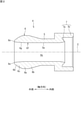
- FIG. 2 is an axial sectional view showing the inner ring 4.
- the bulging portion 6 of the inner ring 4 has a maximum thickness portion 6a having a maximum radial thickness and a first thickness changing portion 6b formed inside the maximum thickness portion 6a in the axial direction. And a second thickness changing portion 6c formed on the outer side in the axial direction of the maximum thickness portion 6a.
- the maximum thickness portion 6a is formed over a predetermined length in the axial direction.
- the outer peripheral surface of the first thickness changing portion 6b is formed so as to gradually reduce the diameter from the inner end in the axial direction of the maximum thickness portion 6a toward the inner side in the axial direction.
- the first thickness changing portion 6b is formed so that the thickness in the radial direction gradually decreases from the inner end in the axial direction of the maximum thickness portion 6a toward the inner side in the axial direction.
- the axial inner end of the first thickness changing portion 6b is connected to the main body portion 5.
- the outer peripheral surface of the first thickness changing portion 6b is formed so as to be inclined linearly in the cross-sectional view, but may be formed so as to be inclined in a curved line in the cross-sectional view. ..
- the outer peripheral surface 6d of the second thickness changing portion 6c is formed so as to gradually reduce the diameter from the axially outer end of the maximum thickness portion 6a toward the axially outer side.
- the outer peripheral surface 6d of the second thickness changing portion 6c is formed so as to be inclined in a curved shape in a cross-sectional view.
- the second thickness changing portion 6c is formed so that the thickness in the radial direction gradually decreases from the inner end in the axial direction to the outer end in the axial direction, that is, the thickness is tapered.
- the outer peripheral surface 6d of the second thickness changing portion 6c may be formed so as to be linearly inclined in a cross-sectional view.
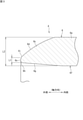
- FIG. 3 is an enlarged cross-sectional view of a main part of FIG.
- a flat surface 6e extending in the radial direction is formed at the axially outer end of the second thickness changing portion 6c in the bulging portion 6.
- "extending in the radial direction” means not only extending along a direction orthogonal to the axis C of the inner ring 4, but also extending along a direction slightly inclined with respect to the orthogonal direction. Including cases.
- the inclination angle of the flat surface 6e with respect to the orthogonal direction Is preferably 1 ° or more and 10 ° or less.
- the inclination angle of the flat surface 6e with respect to the orthogonal direction Is preferably 1 ° or more and 20 ° or less.
- the second thickness changing portion 6c formed so as to taper from the inner end in the axial direction toward the outer end in the axial direction is formed at the outer end in the axial direction. Since it has a flat surface 6e extending in the radial direction, the thickness in the radial direction (thickness dimension L1 described later) at the axial outer end of the second thickness changing portion 6c can be made thicker than before. As a result, the strength at the axially outer end portion (second thickness changing portion 6c) of the bulging portion 6 is increased as compared with the conventional case, so that the union nut 3 is pressed into the tip portion of the tube 8 with the bulging portion 6 pressed into the tip portion.
- the inner peripheral surface 6f of the bulging portion 6 has a tapered surface 6g that is inclined so as to gradually expand the diameter from the intermediate portion in the axial direction of the maximum thickness portion 6a toward the outer end in the axial direction of the second thickness changing portion 6c. Is formed.
- the tapered surface 6g in the present embodiment has a diameter larger than the inner peripheral surface 5a of the main body 5 even if the second thickness changing portion 6c collapses inward when the union nut 3 presses the enlarged diameter portion 8b of the tube 8. It is tilted to the extent that it does not protrude inward (see FIG. 1).
- the inner peripheral surface 6f of the bulging portion 6 becomes the main body portion. It is possible to suppress the protrusion from the inner peripheral surface 5a of 5 inward in diameter. As a result, it is possible to prevent the flow of the chemical solution in the fluid flow path 4a of the inner ring 4 from being obstructed by the inner peripheral surface 6f of the bulging portion 6.
- the tapered surface 6g of the present embodiment is formed so as to be inclined linearly in a cross-sectional view, it may be formed so as to be inclined so as to be curved.
- a chamfered portion 6h is formed at a corner portion (first corner portion) formed by the flat surface 6e and the tapered surface 6g of the bulging portion 6.
- the first corner portion is subjected to R chamfering.
- FIG. 1 when the union nut 3 presses the enlarged diameter portion 8b of the tube 8, a recess formed between the corner portion of the bulging portion 6 and the inner peripheral surface of the tube 8 is formed. Even if the chemical solution enters the 9, the chemical solution in the recess 9 easily flows to the fluid flow path 4a side along the chamfered portion 6h. As a result, it is possible to prevent the chemical solution from remaining in the recess 9.
- the chamfered portion 6h may have a C chamfered portion on the first corner portion.
- a chamfered portion 6i is formed at a corner portion (second corner portion) formed by the flat surface 6e and the outer peripheral surface 6d of the second thickness changing portion 6c in the bulging portion 6.
- the second corner portion is subjected to R chamfering.
- the chamfered portion 6i may have a C chamfered portion on the second corner portion. Further, it is not always necessary to form the chamfered portion 6i at the corner portion formed by the flat surface 6e and the outer peripheral surface 6d.
- the radial thickness dimension L1 at the axial outer end of the bulging portion 6 is set to 3% or more and 30% or less with respect to the maximum radial thickness dimension L2 of the bulging portion 6, and will be described later. In order to improve the effect of suppressing collapse, it is desirable that it is set to 5% or more and 20% or less.
- the maximum thickness dimension L2 is a radial thickness dimension in the maximum thickness portion 6a of the bulging portion 6.
- the "diametrical thickness dimension" at the axial outer end is the intersection of the radial outer end of the bulging portion 6 at the axial outer end (in this embodiment, the extension line of the flat surface 6e and the extension line of the outer peripheral surface 6d). ) To the inner end of the diameter (in this embodiment, the intersection of the extension line of the flat surface 6e and the extension line of the tapered surface 6g).
- the strength of the bulging portion 6 at the outer end portion in the axial direction is further increased.
- the union nut 3 presses the enlarged diameter portion 8b of the tube 8 it is possible to further prevent the axially outer end portion of the bulging portion 6 from collapsing inward in diameter.
- the surface pressure between the contact surfaces of the axially outer end of the bulge 6 and the tube 8 is further increased, so that the infiltration of the chemical solution between these contact surfaces can be effectively suppressed. ..
- the inner peripheral surface 6f of the bulging portion 6 has a diameter. It is possible to further suppress inward protrusion. As a result, it is possible to effectively prevent the flow of the chemical solution in the fluid flow path 4a of the inner ring 4 from being obstructed by the inner peripheral surface 6f of the bulging portion 6.
- the pipe fitting and the inner ring of the present invention can be applied not only to the semiconductor manufacturing apparatus but also to the liquid crystal / organic EL field, the medical / pharmaceutical field, the automobile-related field, and the like.
Landscapes
- Engineering & Computer Science (AREA)
- General Engineering & Computer Science (AREA)
- Mechanical Engineering (AREA)
- Joints With Pressure Members (AREA)
- Joints That Cut Off Fluids, And Hose Joints (AREA)
- Joints With Sleeves (AREA)
Abstract
管継手1のインナーリング4は、軸方向外端部において径外側に突出して形成され、チューブ8の先端部内に圧入される膨出部6を備え、膨出部6の径内側に流体流路4aが形成されている。膨出部6は、軸方向の断面視において、軸方向内側から軸方向外端へ向かって先細るように形成されており、軸方向外端に形成された径方向に延びる平坦面6eを有する。
Description
本発明は、インナーリング、及び管継手に関する。
半導体製造、医療・医薬品製造、及び食品加工・化学工業等の各種技術分野の製造工程では、薬液、高純度液、超純水、或いは洗浄液等の流体が流れる配管経路において、チューブや流体デバイスに形成された流路同士を接続する接続構造として、例えば合成樹脂製の管継手が採用されている。このような管継手として、チューブの先端部の内周側に装着されるインナーリングと、チューブの先端部の外周側に装着される円筒状の継手本体と、継手本体の外周側に装着されるユニオンナットと、を備えたものが知られている(例えば、特許文献1参照)。
インナーリングは、円筒状の本体部と、本体部の軸方向一端部において径外側へ突出して形成された膨出部と、本体部の軸方向他端部に形成されたシール部と、を有している。インナーリングの内部には流体流路が形成されている。インナーリングの膨出部は、チューブの先端部内に圧入されて、当該チューブの先端部を拡径する。ユニオンナットは、継手本体に装着されるとともに、インナーリングの膨出部によって拡径したチューブの外周面を押圧する。これにより、インナーリングのシール部が、継手本体に形成されたシール溝に圧力される。
前記インナーリングにおける膨出部の断面形状は、軸方向中央部から軸方向外端へ向かって徐々に先細るように形成され、膨出部の軸方向外端は先鋭に形成されているので、膨出部の径方向の厚みは、軸方向外端において最も薄くなっている。このため、ユニオンナットがチューブの拡径部分を押圧するときに、膨出部の軸方向外端部は、強度不足により径内側(流体流路側)へ倒れ込む(とび出る)ように変形する場合がある。このような倒れ込みが生じると、膨出部の軸方向外端部とチューブとの接触面同士の面圧が不足することで、これらの接触面間に隙間が生じてしまう。そうすると、前記接触面間の隙間に流体が浸入し、その流体が残存することで、配管経路を流れる流体の置換特性が低下し、配管経路のフラッシングに時間を要する等の悪影響が生じる。
本発明はこのような事情に鑑みてなされたものであり、膨出部の軸方向外端部が径内側へ倒れ込むのを抑制することができるインナーリング及び管継手を提供することを目的とする。
(1)本発明のインナーリングは、軸方向外端部において径外側に突出して形成され、チューブの先端部内に圧入される膨出部を備え、前記膨出部の径内側に流体流路が形成されたインナーリングであって、前記膨出部は、軸方向の断面視において、軸方向内側から軸方向外端へ向かって先細るように形成されており、軸方向外端に形成された径方向に延びる平坦面を有する。
本発明のインナーリングによれば、軸方向内側から軸方向外端へ向かって先細るように形成された膨出部は、軸方向外端に形成された径方向に延びる平坦面を有するので、膨出部の軸方向外端における径方向の厚みを従来よりも厚くすることができる。これにより、膨出部の軸方向外端部における強度が従来よりも増すので、膨出部がチューブの先端部内に圧入された状態でユニオンナットによってチューブが押圧されても、膨出部の軸方向外端部が径内側(流体流路側)へ倒れ込むのを抑制することができる。その結果、膨出部の軸方向外端部とチューブとの接触面同士の面圧が従来よりも高くなるので、これらの接触面間に流体が浸入するのを抑制することができる。
(2)前記膨出部は、その内周面において軸方向内側から軸方向外端へ向かって漸次拡径するように傾斜するテーパ面を有するのが好ましい。
この場合、ユニオンナットがチューブを押圧するときに、膨出部が径内側へ倒れ込んでも、膨出部の内周面が径内側へ突出するのを抑制することができる。これにより、インナーリングの流体流路における流体の流れが、膨出部の内周面によって阻害されるのを抑制することができる。
この場合、ユニオンナットがチューブを押圧するときに、膨出部が径内側へ倒れ込んでも、膨出部の内周面が径内側へ突出するのを抑制することができる。これにより、インナーリングの流体流路における流体の流れが、膨出部の内周面によって阻害されるのを抑制することができる。
(3)前記膨出部は、前記テーパ面と前記平坦面とがなす角部に形成された面取り部を有するのが好ましい。
この場合、膨出部の前記角部とチューブとの間に形成される窪みに流体が入り込んでも、その窪み内の流体は、面取り部によって流体流路側へ流れ易くなるので、前記窪み内に流体が残存するのを抑制することができる。
この場合、膨出部の前記角部とチューブとの間に形成される窪みに流体が入り込んでも、その窪み内の流体は、面取り部によって流体流路側へ流れ易くなるので、前記窪み内に流体が残存するのを抑制することができる。
(4)前記膨出部の軸方向外端における径方向の厚み寸法は、前記膨出部における径方向の最大厚み寸法に対して、3%以上かつ30%以下であるのが好ましい。
この場合、膨出部の軸方向外端における径方向の厚み寸法を、膨出部における径方向の最大厚み寸法に対して3%以上にすることで、膨出部の軸方向外端部における強度がさらに増す。これにより、ユニオンナットによってチューブを押圧するときに、膨出部の軸方向外端部が径内側へ倒れ込むのをさらに抑制することができる。その結果、膨出部の軸方向外端部とチューブとの接触面同士の面圧がさらに高くなるので、これらの接触面間に流体が浸入するのを効果的に抑制することができる。
この場合、膨出部の軸方向外端における径方向の厚み寸法を、膨出部における径方向の最大厚み寸法に対して3%以上にすることで、膨出部の軸方向外端部における強度がさらに増す。これにより、ユニオンナットによってチューブを押圧するときに、膨出部の軸方向外端部が径内側へ倒れ込むのをさらに抑制することができる。その結果、膨出部の軸方向外端部とチューブとの接触面同士の面圧がさらに高くなるので、これらの接触面間に流体が浸入するのを効果的に抑制することができる。
また、膨出部の軸方向外端における径方向の厚み寸法を、膨出部における径方向の最大厚み寸法に対して30%以下にすることで、膨出部の軸方向外端部が径内側へ倒れ込んだときに、膨出部の内周面が径内側へ突出するのをさらに抑制することができる。これにより、インナーリングの流体流路における流体の流れが、膨出部の内周面によって阻害されるのを効果的に抑制することができる。
(5)本発明の管継手は、外周に雄ねじ部が形成された継手本体と、前記雄ねじ部に締め付けられる雌ねじ部が内周に形成されたユニオンナットと、前記(1)から(4)のいずれかに記載のインナーリングと、を備える。
本発明の管継手によれば、インナーリングにおいて、軸方向内側から軸方向外端へ向かって先細るように形成された膨出部は、軸方向外端に形成された径方向に延びる平坦面を有するので、膨出部の軸方向外端における径方向の厚みを従来よりも厚くすることができる。これにより、膨出部の軸方向外端部における強度が従来よりも増すので、膨出部がチューブの先端部内に圧入された状態でユニオンナットによってチューブが押圧されても、膨出部の軸方向外端部が径内側(流体流路側)へ倒れ込むのを抑制することができる。その結果、膨出部の軸方向外端部とチューブとの接触面同士の面圧が従来よりも高くなるので、これらの接触面間に流体が浸入するのを抑制することができる。
本発明によれば、膨出部の軸方向外端部が径内側へ倒れ込むのを抑制することができる。
次に、本発明の好ましい実施形態について添付図面を参照しながら説明する。
[管継手の全体構成]
図1は、本発明の実施形態に係る管継手を示す軸方向の断面図である。図1において、管継手1は、例えば、半導体製造装置で使用される薬液(流体)が流れる配管経路に用いられる。管継手1は、継手本体2と、ユニオンナット3と、インナーリング4と、を備えている。以下、本実施形態では、便宜上、図1の左側を軸方向外側といい、図1の右側を軸方向内側という(図2、図3も同様)。
[管継手の全体構成]
図1は、本発明の実施形態に係る管継手を示す軸方向の断面図である。図1において、管継手1は、例えば、半導体製造装置で使用される薬液(流体)が流れる配管経路に用いられる。管継手1は、継手本体2と、ユニオンナット3と、インナーリング4と、を備えている。以下、本実施形態では、便宜上、図1の左側を軸方向外側といい、図1の右側を軸方向内側という(図2、図3も同様)。
インナーリング4は、例えば、ポリ塩化ビニル(PVC)、ポリプロピレン(PP)、ポリエチレン(PE)、又はフッ素樹脂(パーフルオロアルコキシアルカン(PFA)、ポリテトラフルオロエチレン(PTFE)、又はポリフッ化ビニリデン(PVDF)等)の合成樹脂材料によって、円筒状に形成されている。
インナーリング4は、円筒状に形成された本体部5と、本体部5の軸方向外側に形成された膨出部6と、本体部5の軸方向内側に形成されたシール部7と、を備えている。インナーリング4における本体部5、膨出部6、及びシール部7の各径内側には、流体流路4aが形成されている。流体流路4aは、チューブ8の内部に形成された流路8aと、継手本体2の内部に形成された流路2cとを連通する。
膨出部6は、本体部5の軸方向外側において径外側に突出して形成されている。膨出部6は、合成樹脂製(PFA等)のチューブ8の先端部内に圧入され、当該チューブ8の先端部を拡径する。なお、膨出部6の詳細については後述する。シール部7は、環状の一次シール部7aと、円筒状の二次シール部7bと、を備えている。
一次シール部7aは、本体部5の軸方向内端部の径内側から軸方向内側に突出して形成されている。一次シール部7aの外周面は、軸方向外端から軸方向内端へ向かって漸次縮径して形成されている。一次シール部7aは、継手本体2の一次シール溝2d(後述)に圧入される。二次シール部7bは、本体部5の軸方向内端部の径外側から軸方向内側に突出して形成されている。二次シール部7bは、継手本体2の二次シール溝2e(後述)に圧入される。
継手本体2は、例えば、PVC、PP、PE又はフッ素樹脂(PFAやPTFE等)の合成樹脂材料によって円筒状に形成されている。継手本体2の内径は、薬液の移動を妨げないように、インナーリング4の内径と略同一寸法に設定されている。継手本体2の端部には、受口部2aが形成されている。受口部2aの内周には、チューブ8の先端部内に膨出部6が圧入されたインナーリング4のシール部7が圧入されている。これにより、継手本体2の軸方向外端部は、チューブ8の先端部の外周に装着されている。受口部2aの外周には、雄ねじ部2bが形成されている。
継手本体2は、受口部2aよりも径内側に形成された、環状の一次シール溝2d及び環状の二次シール溝2eを有している。一次シール溝2dは、継手本体2の径内側において、軸方向外端から軸方向内端へ向かって漸次縮径するように切り欠かれたテーパ形状とされている。二次シール溝2eは、継手本体2において一次シール溝2dよりも径外側に形成されている。
ユニオンナット3は、例えば、PVC、PP、PE又はフッ素樹脂(PFAやPTFE等)の合成樹脂材料によって円筒状に形成されている。ユニオンナット3は、軸方向内側の内周に形成された雌ねじ部3aと、軸方向外側において径内側に突出して形成された押圧部3bと、を有している。雌ねじ部3aは、継手本体2の雄ねじ部2bに締め付けられている。その締め付けによって、ユニオンナット3は継手本体2に装着されるとともに、押圧部3bの軸方向内端部は、チューブ8の外周面におけるインナーリング4の膨出部6により拡径された拡径部8bを押圧する。
以上の構成により、ユニオンナット3の雌ねじ部3aを継手本体2の雄ねじ部2bに締め付けると、インナーリング4の一次シール部7a及び二次シール部7bは、それぞれ継手本体2の一次シール溝2d及び二次シール溝2eに圧入される。これにより、インナーリング4と継手本体2との接続部分のシール性能を確保することができる。また、ユニオンナット3の押圧部3bがチューブ8の拡径部8bを押圧することで、チューブ8の抜け出しを防止することができる。
[膨出部の構成]
図2は、インナーリング4を示す軸方向の断面図である。図1及び図2において、インナーリング4の膨出部6は、その径方向の厚みが最大となる最大厚み部6aと、最大厚み部6aの軸方向内側に形成された第1厚み変化部6bと、最大厚み部6aの軸方向外側に形成された第2厚み変化部6cと、を有している。
図2は、インナーリング4を示す軸方向の断面図である。図1及び図2において、インナーリング4の膨出部6は、その径方向の厚みが最大となる最大厚み部6aと、最大厚み部6aの軸方向内側に形成された第1厚み変化部6bと、最大厚み部6aの軸方向外側に形成された第2厚み変化部6cと、を有している。
最大厚み部6aは、軸方向の所定長さにわたって形成されている。第1厚み変化部6bの外周面は、最大厚み部6aの軸方向内端から軸方向内側へ向かって漸次縮径するように形成されている。これにより、第1厚み変化部6bは、最大厚み部6aの軸方向内端から軸方向内側へ向かって、径方向の厚みが漸次薄くなるように形成されている。第1厚み変化部6bの軸方向内端は、本体部5に接続されている。なお、本実施形態では、第1厚み変化部6bの外周面は、断面視において直線状に傾斜するように形成されているが、断面視において曲線状に傾斜するように形成されていてもよい。
第2厚み変化部6cの外周面6dは、最大厚み部6aの軸方向外端から軸方向外側へ向かって漸次縮径するように形成されている。本実施形態では、第2厚み変化部6cの外周面6dは、断面視において曲線状に傾斜するように形成されている。これにより、第2厚み変化部6cは、軸方向内端から軸方向外端へ向かって径方向の厚みが漸次薄くなるように、つまり先細るように形成されている。なお、第2厚み変化部6cの外周面6dは、断面視において直線状に傾斜するように形成されていてもよい。
図3は、図2の要部拡大断面図である。図2及び図3において、膨出部6における第2厚み変化部6cの軸方向外端には、径方向に延びる平坦面6eが形成されている。ここで、「径方向に延びる」とは、インナーリング4の軸線Cに対して直交する方向に沿って延びる場合だけでなく、前記直交する方向に対して多少傾斜している方向に沿って延びる場合も含む。
平坦面6eの径内端が径外端よりも軸方向外側に位置するように、平坦面6eが前記直交する方向に対して傾斜している場合、前記直交する方向に対する平坦面6eの傾斜角度は、1°以上かつ10°以下であるのが好ましい。
平坦面6eの径内端が径外端よりも軸方向内側に位置するように、平坦面6eが前記直交する方向に対して傾斜している場合、前記直交する方向に対する平坦面6eの傾斜角度は、1°以上かつ20°以下であるのが好ましい。
平坦面6eの径内端が径外端よりも軸方向内側に位置するように、平坦面6eが前記直交する方向に対して傾斜している場合、前記直交する方向に対する平坦面6eの傾斜角度は、1°以上かつ20°以下であるのが好ましい。
以上のように、インナーリング4の膨出部6において、軸方向内端から軸方向外端へ向かって先細るように形成された第2厚み変化部6cは、その軸方向外端に形成された径方向に延びる平坦面6eを有するので、第2厚み変化部6cの軸方向外端における径方向の厚み(後述する厚み寸法L1)を従来よりも厚くすることができる。これにより、膨出部6の軸方向外端部(第2厚み変化部6c)における強度が従来よりも増すので、膨出部6がチューブ8の先端部内に圧入された状態でユニオンナット3を継手本体2に締め付けるときに、ユニオンナット3がチューブ8の拡径部8bを押圧しても、膨出部6の軸方向外端部が径内側(流体流路4a側)へ倒れ込むのを抑制することができる。その結果、膨出部6の軸方向外端部とチューブ8との接触面同士の面圧が従来よりも高くなるので、これらの接触面間に薬液が浸入するのを抑制することができる。
膨出部6の内周面6fには、最大厚み部6aの軸方向の途中部から第2厚み変化部6cの軸方向外端へ向かって漸次拡径するように傾斜しているテーパ面6gが形成されている。本実施形態におけるテーパ面6gは、ユニオンナット3がチューブ8の拡径部8bを押圧したときに、第2厚み変化部6cが径内側へ倒れ込んでも、本体部5の内周面5aよりも径内側へ突出しない程度に傾斜している(図1参照)。
これにより、ユニオンナット3がチューブ8の拡径部8bを押圧したときに、膨出部6の第2厚み変化部6cが径内側へ倒れ込んでも、膨出部6の内周面6fが本体部5の内周面5aよりも径内側へ突出するのを抑制することができる。これにより、インナーリング4の流体流路4aにおける薬液の流れが、膨出部6の内周面6fによって阻害されるのを抑制することができる。なお、本実施形態のテーパ面6gは、断面視において直線状に傾斜するように形成されているが、曲線状に傾斜するように形成されていてもよい。
膨出部6の平坦面6eとテーパ面6gとがなす角部(第1角部)には、面取り部6hが形成されている。本実施形態の面取り部6hは、例えば第1角部にR面取り加工が施されたものである。これにより、図1に示すように、ユニオンナット3がチューブ8の拡径部8bを押圧したときに、膨出部6の前記角部とチューブ8の内周面との間に形成される窪み9に薬液が入り込んでも、窪み9内の薬液は、面取り部6hに沿って流体流路4a側へ流れ易くなる。その結果、窪み9内に薬液が残存するのを抑制することができる。なお、面取り部6hは、第1角部にC面取り加工が施されたものでもよい。
図3に戻り、膨出部6における第2厚み変化部6cの平坦面6eと外周面6dとがなす角部(第2角部)には、面取り部6iが形成されている。本実施形態の面取り部6iは、例えば第2角部にR面取り加工が施されたものである。なお、面取り部6iは、第2角部にC面取り加工が施されたものでもよい。また、平坦面6eと外周面6dとがなす角部には、必ずしも面取り部6iを形成する必要はない。
膨出部6の軸方向外端における径方向の厚み寸法L1は、膨出部6における径方向の最大厚み寸法L2に対して、3%以上かつ30%以下に設定されており、後述するように倒れ込みの抑制効果を向上させるためには5%以上かつ20%以下に設定されていることが望ましい。最大厚み寸法L2は、膨出部6の最大厚み部6aにおける径方向の厚み寸法である。軸方向外端のおける「径方向の厚み寸法」とは、膨出部6の軸方向外端における径外端(本実施形態では平坦面6eの延長線と外周面6dの延長線との交点)から、径内端(本実施形態では平坦面6eの延長線とテーパ面6gの延長線との交点)までの径方向寸法を意味する。
厚み寸法L1を最大厚み寸法L2に対して3%以上にすることで、膨出部6の軸方向外端部における強度がさらに増す。これにより、ユニオンナット3がチューブ8の拡径部8bを押圧するときに、膨出部6の軸方向外端部が径内側へ倒れ込むのをさらに抑制することができる。その結果、膨出部6の軸方向外端部とチューブ8との接触面同士の面圧がさらに高くなるので、これらの接触面間に薬液が浸入するのを効果的に抑制することができる。
厚み寸法L1を最大厚み寸法L2に対して30%以下にすることで、膨出部6の第2厚み変化部6cが径内側へ倒れ込んだときに、膨出部6の内周面6fが径内側へ突出するのをさらに抑制することができる。これにより、インナーリング4の流体流路4aにおける薬液の流れが、膨出部6の内周面6fによって阻害されるのを効果的に抑制することができる。
[その他]
本発明の管継手及びインナーリングは、半導体製造装置以外に、液晶・有機EL分野、医療・医薬分野、または自動車関連分野などにおいても適用することができる。
本発明の管継手及びインナーリングは、半導体製造装置以外に、液晶・有機EL分野、医療・医薬分野、または自動車関連分野などにおいても適用することができる。
今回開示された実施形態はすべての点で例示であって制限的なものではないと考えられるべきである。本発明の範囲は、上記した意味ではなく、請求の範囲によって示され、請求の範囲と均等の意味、及び範囲内でのすべての変更が含まれることが意図される。
1 管継手
2 継手本体
2b 雄ねじ部
3 ユニオンナット
3a 雌ねじ部
4 インナーリング
6 膨出部
6e 平坦面
6f 内周面
6g テーパ面
6h 面取り部
L1 厚み寸法
L2 最大厚み寸法
2 継手本体
2b 雄ねじ部
3 ユニオンナット
3a 雌ねじ部
4 インナーリング
6 膨出部
6e 平坦面
6f 内周面
6g テーパ面
6h 面取り部
L1 厚み寸法
L2 最大厚み寸法
Claims (5)
- 軸方向外端部において径外側に突出して形成され、チューブの先端部内に圧入される膨出部を備え、前記膨出部の径内側に流体流路が形成されたインナーリングであって、
前記膨出部は、軸方向の断面視において、軸方向内側から軸方向外端へ向かって先細るように形成されており、軸方向外端に形成された径方向に延びる平坦面を有する、インナーリング。 - 前記膨出部は、その内周面において軸方向内側から軸方向外端へ向かって漸次拡径するように傾斜するテーパ面を有する、請求項1に記載のインナーリング。
- 前記膨出部は、前記テーパ面と前記平坦面とがなす角部に形成された面取り部を有する、請求項2に記載のインナーリング。
- 前記膨出部の軸方向外端における径方向の厚み寸法は、前記膨出部における径方向の最大厚み寸法に対して、3%以上かつ30%以下である、請求項1から請求項3のいずれか1項に記載のインナーリング。
- 外周に雄ねじ部が形成された継手本体と、
前記雄ねじ部に締め付けられる雌ねじ部が内周に形成されたユニオンナットと、
請求項1から請求項4のいずれか1項に記載のインナーリングと、を備える管継手。
Priority Applications (4)
| Application Number | Priority Date | Filing Date | Title |
|---|---|---|---|
| DE112021003753.6T DE112021003753T5 (de) | 2020-07-14 | 2021-03-31 | Innenring und rohrverbindung |
| US17/924,215 US20230175621A1 (en) | 2020-07-14 | 2021-03-31 | Inner ring and pipe joint |
| CN202180060868.9A CN116194701A (zh) | 2020-07-14 | 2021-03-31 | 内环以及管接头 |
| KR1020227042907A KR20230004885A (ko) | 2020-07-14 | 2021-03-31 | 이너링, 및 관 이음매 |
Applications Claiming Priority (2)
| Application Number | Priority Date | Filing Date | Title |
|---|---|---|---|
| JP2020-120535 | 2020-07-14 | ||
| JP2020120535A JP2022017782A (ja) | 2020-07-14 | 2020-07-14 | インナーリング、及び管継手 |
Publications (1)
| Publication Number | Publication Date |
|---|---|
| WO2022014109A1 true WO2022014109A1 (ja) | 2022-01-20 |
Family
ID=79554731
Family Applications (1)
| Application Number | Title | Priority Date | Filing Date |
|---|---|---|---|
| PCT/JP2021/014020 Ceased WO2022014109A1 (ja) | 2020-07-14 | 2021-03-31 | インナーリング、及び管継手 |
Country Status (6)
| Country | Link |
|---|---|
| US (1) | US20230175621A1 (ja) |
| JP (1) | JP2022017782A (ja) |
| KR (1) | KR20230004885A (ja) |
| CN (1) | CN116194701A (ja) |
| DE (1) | DE112021003753T5 (ja) |
| WO (1) | WO2022014109A1 (ja) |
Families Citing this family (1)
| Publication number | Priority date | Publication date | Assignee | Title |
|---|---|---|---|---|
| JP1697658S (ja) * | 2021-01-08 | 2021-10-18 |
Citations (6)
| Publication number | Priority date | Publication date | Assignee | Title |
|---|---|---|---|---|
| JPS54142620A (en) * | 1978-04-14 | 1979-11-07 | Walterscheid Gmbh Jean | Screw connector |
| JPS5828086A (ja) * | 1981-08-05 | 1983-02-18 | エルメト−ア−マツ−レン・ゲゼルシヤフト・ミツト・ベシユレンクテル・ハフツング | 管を気密に継ぐねじ継手装置 |
| JPH0590089U (ja) * | 1992-05-22 | 1993-12-07 | 株式会社柿崎製作所 | 樹脂管継手 |
| WO2000028254A1 (en) * | 1998-11-05 | 2000-05-18 | Nippon Pillar Packing Co., Ltd. | Resin pipe joint |
| JP2012163132A (ja) * | 2011-02-04 | 2012-08-30 | Flowell Corp | チューブ継手 |
| JP2018168947A (ja) * | 2017-03-30 | 2018-11-01 | 日本ピラー工業株式会社 | 樹脂製管継手 |
Family Cites Families (12)
| Publication number | Priority date | Publication date | Assignee | Title |
|---|---|---|---|---|
| US4614372A (en) * | 1985-04-12 | 1986-09-30 | Vestol Sa. | Device for joining a pipe and a connection piece |
| JPH0452556Y2 (ja) * | 1988-10-26 | 1992-12-10 | ||
| JP2602756B2 (ja) * | 1992-05-18 | 1997-04-23 | 日本ピラー工業 株式会社 | 管継手の取付け方法 |
| JP3706813B2 (ja) * | 2001-06-01 | 2005-10-19 | 日本ピラー工業株式会社 | 樹脂製管継手におけるチューブ抜止め方法及びチューブ抜止め構造 |
| DE102005011958B3 (de) * | 2005-03-14 | 2006-06-22 | Uponor Innovation Ab | Klemmfitting für ein Heizungs- und/oder Sanitärrohr |
| JP5560222B2 (ja) * | 2011-03-15 | 2014-07-23 | 日本ピラー工業株式会社 | 樹脂製管継手 |
| JP5871855B2 (ja) * | 2013-05-08 | 2016-03-01 | 日本ピラー工業株式会社 | インナーリング |
| JP5878143B2 (ja) * | 2013-05-08 | 2016-03-08 | 日本ピラー工業株式会社 | 合成樹脂製管継手 |
| JP5873833B2 (ja) * | 2013-05-08 | 2016-03-01 | 日本ピラー工業株式会社 | 管接続装置 |
| JP5996000B2 (ja) * | 2015-01-23 | 2016-09-21 | 日本ピラー工業株式会社 | 樹脂製管継手構造 |
| JP5982511B2 (ja) * | 2015-02-13 | 2016-08-31 | 日本ピラー工業株式会社 | 樹脂製管継手構造 |
| JP7229624B2 (ja) * | 2018-12-19 | 2023-02-28 | 日本ピラー工業株式会社 | 管継手 |
-
2020
- 2020-07-14 JP JP2020120535A patent/JP2022017782A/ja active Pending
-
2021
- 2021-03-31 DE DE112021003753.6T patent/DE112021003753T5/de not_active Withdrawn
- 2021-03-31 KR KR1020227042907A patent/KR20230004885A/ko not_active Ceased
- 2021-03-31 WO PCT/JP2021/014020 patent/WO2022014109A1/ja not_active Ceased
- 2021-03-31 US US17/924,215 patent/US20230175621A1/en not_active Abandoned
- 2021-03-31 CN CN202180060868.9A patent/CN116194701A/zh active Pending
Patent Citations (6)
| Publication number | Priority date | Publication date | Assignee | Title |
|---|---|---|---|---|
| JPS54142620A (en) * | 1978-04-14 | 1979-11-07 | Walterscheid Gmbh Jean | Screw connector |
| JPS5828086A (ja) * | 1981-08-05 | 1983-02-18 | エルメト−ア−マツ−レン・ゲゼルシヤフト・ミツト・ベシユレンクテル・ハフツング | 管を気密に継ぐねじ継手装置 |
| JPH0590089U (ja) * | 1992-05-22 | 1993-12-07 | 株式会社柿崎製作所 | 樹脂管継手 |
| WO2000028254A1 (en) * | 1998-11-05 | 2000-05-18 | Nippon Pillar Packing Co., Ltd. | Resin pipe joint |
| JP2012163132A (ja) * | 2011-02-04 | 2012-08-30 | Flowell Corp | チューブ継手 |
| JP2018168947A (ja) * | 2017-03-30 | 2018-11-01 | 日本ピラー工業株式会社 | 樹脂製管継手 |
Also Published As
| Publication number | Publication date |
|---|---|
| CN116194701A (zh) | 2023-05-30 |
| US20230175621A1 (en) | 2023-06-08 |
| DE112021003753T5 (de) | 2023-04-27 |
| JP2022017782A (ja) | 2022-01-26 |
| KR20230004885A (ko) | 2023-01-06 |
Similar Documents
| Publication | Publication Date | Title |
|---|---|---|
| JP6805045B2 (ja) | 樹脂製管継手 | |
| US9109728B2 (en) | Resinous pipe joint | |
| JP5871855B2 (ja) | インナーリング | |
| WO2021199570A1 (ja) | シール部材 | |
| US20250092968A1 (en) | Pipe joint | |
| JP7337737B2 (ja) | シール部材、及び管継手 | |
| WO2022059267A1 (ja) | ガスケット、及び流路継手構造 | |
| WO2022014109A1 (ja) | インナーリング、及び管継手 | |
| KR102669499B1 (ko) | 슬리브 및 그것을 구비한 이음매 | |
| US12025244B2 (en) | Inner ring and pipe joint | |
| JP7265861B2 (ja) | 管継手 | |
| JP2021038853A (ja) | 樹脂製管継手 |
Legal Events
| Date | Code | Title | Description |
|---|---|---|---|
| 121 | Ep: the epo has been informed by wipo that ep was designated in this application |
Ref document number: 21843505 Country of ref document: EP Kind code of ref document: A1 |
|
| ENP | Entry into the national phase |
Ref document number: 20227042907 Country of ref document: KR Kind code of ref document: A |
|
| 122 | Ep: pct application non-entry in european phase |
Ref document number: 21843505 Country of ref document: EP Kind code of ref document: A1 |