WO2022014252A1 - 情報処理装置および情報処理方法 - Google Patents
情報処理装置および情報処理方法 Download PDFInfo
- Publication number
- WO2022014252A1 WO2022014252A1 PCT/JP2021/023104 JP2021023104W WO2022014252A1 WO 2022014252 A1 WO2022014252 A1 WO 2022014252A1 JP 2021023104 W JP2021023104 W JP 2021023104W WO 2022014252 A1 WO2022014252 A1 WO 2022014252A1
- Authority
- WO
- WIPO (PCT)
- Prior art keywords
- human body
- moving
- moving body
- information processing
- captured image
- Prior art date
- Legal status (The legal status is an assumption and is not a legal conclusion. Google has not performed a legal analysis and makes no representation as to the accuracy of the status listed.)
- Ceased
Links
Images





Classifications
-
- G—PHYSICS
- G06—COMPUTING OR CALCULATING; COUNTING
- G06T—IMAGE DATA PROCESSING OR GENERATION, IN GENERAL
- G06T7/00—Image analysis
- G06T7/20—Analysis of motion
- G06T7/254—Analysis of motion involving subtraction of images
-
- G—PHYSICS
- G06—COMPUTING OR CALCULATING; COUNTING
- G06T—IMAGE DATA PROCESSING OR GENERATION, IN GENERAL
- G06T7/00—Image analysis
- G06T7/20—Analysis of motion
- G06T7/246—Analysis of motion using feature-based methods, e.g. the tracking of corners or segments
- G06T7/248—Analysis of motion using feature-based methods, e.g. the tracking of corners or segments involving reference images or patches
-
- G—PHYSICS
- G06—COMPUTING OR CALCULATING; COUNTING
- G06T—IMAGE DATA PROCESSING OR GENERATION, IN GENERAL
- G06T7/00—Image analysis
- G06T7/20—Analysis of motion
- G06T7/215—Motion-based segmentation
-
- G—PHYSICS
- G06—COMPUTING OR CALCULATING; COUNTING
- G06T—IMAGE DATA PROCESSING OR GENERATION, IN GENERAL
- G06T7/00—Image analysis
- G06T7/20—Analysis of motion
- G06T7/269—Analysis of motion using gradient-based methods
-
- G—PHYSICS
- G06—COMPUTING OR CALCULATING; COUNTING
- G06T—IMAGE DATA PROCESSING OR GENERATION, IN GENERAL
- G06T7/00—Image analysis
- G06T7/60—Analysis of geometric attributes
-
- G—PHYSICS
- G06—COMPUTING OR CALCULATING; COUNTING
- G06V—IMAGE OR VIDEO RECOGNITION OR UNDERSTANDING
- G06V40/00—Recognition of biometric, human-related or animal-related patterns in image or video data
- G06V40/10—Human or animal bodies, e.g. vehicle occupants or pedestrians; Body parts, e.g. hands
-
- G—PHYSICS
- G06—COMPUTING OR CALCULATING; COUNTING
- G06T—IMAGE DATA PROCESSING OR GENERATION, IN GENERAL
- G06T2207/00—Indexing scheme for image analysis or image enhancement
- G06T2207/20—Special algorithmic details
- G06T2207/20084—Artificial neural networks [ANN]
-
- G—PHYSICS
- G06—COMPUTING OR CALCULATING; COUNTING
- G06T—IMAGE DATA PROCESSING OR GENERATION, IN GENERAL
- G06T2207/00—Indexing scheme for image analysis or image enhancement
- G06T2207/30—Subject of image; Context of image processing
- G06T2207/30196—Human being; Person
Definitions
- the present invention relates to an information processing apparatus and an information processing method.
- Patent Document 1 discloses a technique for reducing a processing load when detecting an object from a moving image by setting a moving object region in which a change occurs between frames constituting the moving image as a detection target region.
- the processing load for human body detection is sufficiently reduced because the analysis target includes moving objects other than the human body, for example, moving objects other than the human body such as corrugated cardboard on a conveyor in a factory. Not done. Further, when detecting using the shape information of an object, the human body whose shape changes depending on the posture may not be detected accurately.
- One aspect of the present invention is to provide a technique for accurately detecting the human body in real time.
- the present invention adopts the following configuration in order to achieve the above object.
- the first aspect of the present disclosure is to determine the distance between a moving body detection unit that detects a moving body from an image captured by a fish-eye camera and a predetermined two points on the contour of a moving body region including the moving body in the captured image.
- the human body determination unit for determining whether or not the moving body is a human body and the human body determination unit for determining that the human body is a human body. It is an information processing apparatus including a human body detection unit that detects a human body from a moving body region including a moving body.
- the “distance between two predetermined points on the contour of the moving body region including the moving body” is a distance corresponding to the height of the human body when the moving body is a human body. Hereinafter, it is also referred to as the length of the moving body.
- the “threshold value range” can be a range of values that the height of the human body can take at a position in the captured image when the human body is photographed.
- the information processing apparatus limits the target area for detecting the human body by motion detection, and further detects the human body only when the moving object is a human body. Therefore, the processing load due to the detection of the human body is reduced, and the information processing apparatus can accurately detect the human body in real time.
- the distance between two predetermined points on the contour of the moving body region including the moving body is the first coordinate which is the closest point or the farthest point from the center coordinate of the captured image in the moving body region, and the straight line passing through the center coordinate and the first coordinate. It may be a distance between the second coordinate and the intersection of the contour of the moving body region and the second coordinate different from the first coordinate.
- the information processing device can calculate the length of the moving object by a simple method.
- the distance between two predetermined points on the contour of the moving body region including the moving body is the distance between the two points where the straight line passing through the coordinates of the center of gravity of the moving body region and the center coordinates of the captured image intersects the contour of the moving body region. good. Even if the shape of the moving body region, which is the human body, changes due to a change in posture such as when a person reaches out, the center of gravity of the moving body region exists on the human body because the human hand is thinner than the torso. Therefore, the information processing device can accurately acquire the height of the human body by calculating the distance between two points where the straight line passing through the coordinates of the center of gravity and the center coordinates of the captured image intersects the contour of the moving body region. ..
- the threshold range may be set for each region in which the captured image is divided into a plurality of areas. Since the image of the human body differs depending on the position in the captured image, the information processing apparatus sets the assumed length of the human body for each divided region as a threshold range. As a result, the information processing apparatus can accurately determine whether or not the detected moving object is a human body.
- the moving object detection unit may detect a moving object by the background subtraction method or the inter-frame subtraction method. Further, the moving object detecting unit may detect a moving object based on the movement and the moving direction of the object commonly captured in the continuous frame of the captured image. Since the information processing device detects a moving object and limits the target area for human body detection to the moving object area including the detected moving object, the load due to unnecessary human body detection can be reduced.
- the information processing device may further include an output unit that outputs information on the human body detected by the human body detection unit.
- the information processing device can output the detection result of the human body by the human body detection unit to a display or the like in real time and present it to the user.
- the information processing device may further include an imaging unit that captures captured images.
- the information processing device can be configured in a simple manner by being integrally configured with the image pickup unit.
- the second aspect of the present invention is a captured image of a moving object detection step in which a computer detects a moving object from an image captured by a fisheye camera, and a distance between two predetermined points on the contour of a moving object region including the moving object.
- the human body determination step for determining whether or not the moving object is a human body and the human body determination step for the human body
- It is an information processing method including a human body detection unit step for detecting a human body from a moving body region including a moving body determined to be present.
- the human body can be detected accurately in real time.
- FIG. 1 is a diagram illustrating an application example of the information processing apparatus according to the embodiment.
- FIG. 2 is a diagram illustrating a hardware configuration of an information processing device.
- FIG. 3 is a diagram illustrating the functional configuration of the information processing apparatus.
- FIG. 4 is a flowchart illustrating the human body detection process.
- FIG. 5 is a diagram illustrating motion detection.
- FIG. 6 is a diagram illustrating a first example of calculating the length of a moving body.
- 7A and 7B are diagrams illustrating a second example of calculating the length of a moving body.
- FIG. 8 is a graph showing the length of the human body according to the distance from the center.
- 9A and 9B are diagrams showing an example of a threshold value set for each region of the imaging range.
- FIG. 10 is a diagram showing an example of determining whether or not the moving body is a human body.
- 11A and 11B are diagrams illustrating a method of detecting a human body from a moving body
- FIG. 1 is a diagram illustrating an application example of the information processing apparatus according to the embodiment.
- the information processing apparatus 1 acquires a camera image (captured image) taken by the camera 10 (imaging unit).
- the camera 10 is, for example, an ultra-wide-angle camera equipped with a fisheye lens capable of acquiring a wide range of image information.
- a camera equipped with a fisheye lens is also called a fisheye camera, an omnidirectional camera, an omnidirectional camera, or the like, but the term "fisheye camera" is used in this specification.
- the image taken by the fisheye camera is distorted in appearance depending on the position in the captured image. For example, when the fisheye camera is placed so as to look down on the floor from the ceiling, the image of the photographed person has the feet facing the center and the crown facing outward.
- the human body is a front image, a rear image, or a side image around the captured image, and a top image at the center of the captured image.
- the information processing device 1 detects a moving object from the captured image acquired from the camera 10 and determines whether or not it is a human body. Since the human body taken with a fish-eye camera is distorted, the distance between the feet of the human body and the crown (height of the human body) differs depending on the position in the captured image.
- the information processing device 1 stores in advance the distance between the foot and the crown, which is assumed according to the position in the captured image, as a threshold range for determining whether or not the detected moving object is a human body.
- the information processing apparatus 1 compares the distance (length of the moving body) between two predetermined points on the contour of the moving body region including the detected moving body with the range of the threshold value set in advance corresponding to the position in the captured image. By doing so, it is possible to determine whether or not the moving body is a human body.
- the information processing device 1 analyzes the moving body region determined to be the human body and detects the human body.
- the information processing apparatus 1 can detect a human body by using a general object recognition algorithm.
- the human body detection algorithm can use a classifier that combines image features such as HoG or Haar-like with boosting.
- the human body detection algorithm may use human body recognition by deep learning (for example, R-CNN, Faster R-CNN, YOLO, SSD, etc.).
- the information processing apparatus 1 can determine the human body-likeness by detecting a moving object from the captured image and comparing it with a preset threshold range corresponding to the position in the captured image.
- the information processing apparatus 1 detects a human body only in a moving body region including a moving body determined to be a human body in the captured image. Therefore, the load due to the human body detection process is reduced.
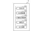
- FIG. 2 is a diagram illustrating a hardware configuration of the information processing apparatus 1.
- the information processing device 1 includes a processor 101, a main storage device 102, an auxiliary storage device 103, a communication interface (I / F) 104, and an output device 105.
- the processor 101 reads the program stored in the auxiliary storage device 103 into the main storage device 102 and executes it, thereby realizing the functions as the functional configurations described with reference to FIG.
- the communication interface 104 is an interface for performing wired or wireless communication.
- the output device 105 is, for example, a device for outputting a display or the like.
- the information processing device 1 may be a general-purpose computer such as a personal computer, a server computer, a tablet terminal, or a smartphone, or may be an embedded computer such as an onboard computer.
- the information processing device 1 may be realized by, for example, distributed computing by a plurality of computer devices, or a part of each functional unit may be realized by a cloud server. Further, a part of each functional unit of the information processing apparatus 1 may be realized by a dedicated hardware apparatus such as FPGA or ASIC.
- the information processing device 1 is connected to the camera 10 by wire (USB cable, LAN cable, etc.) or wirelessly (WiFi, etc.), and receives image data taken by the camera 10.
- the camera 10 is an image pickup device having an optical system including a lens and an image pickup element (an image sensor such as a CCD or CMOS).
- the information processing device 1 may be integrally configured with the camera 10 (imaging unit). Further, a part of the processing of the information processing apparatus 1 such as motion detection and human body determination processing for the captured image may be executed by the camera 10. Further, the result of the human body detection by the information processing device 1 may be transmitted to an external device and presented to the user.
- FIG. 3 is a diagram illustrating the functional configuration of the information processing apparatus 1.
- the information processing apparatus 1 includes a motion detection unit 11, a human body determination unit 12, a human body detection unit 13, an output unit 14, and a determination information database 15 (determination information DB 15).
- the moving object detection unit 11 detects a moving object from the captured image acquired from the camera 10.
- the moving object detection unit 11 uses, for example, a background subtraction method for detecting a change between a captured image and a background image prepared in advance, and an interframe difference method for detecting a change between frames. Can be detected.
- a moving object may be detected based on both the background difference and the frame-to-frame difference.
- the method of detecting a moving object may be a method using an optical flow that estimates the movement and moving direction of an object from a portion that is commonly captured in a continuous frame.
- the human body determination unit 12 determines whether or not the moving body detected by the moving body detecting unit 11 is a human body.
- the human body determination unit 12 determines whether or not the moving body is a human body by, for example, comparing the detected length of the moving body with a threshold range set based on the height of the human body measured at the position of the moving body. It can be determined.
- the human body detection unit 13 detects (recognizes) the human body from the area of the moving body determined by the human body determination unit 12 to be a human body.
- the detection of the human body can be realized by a general object recognition technique such as deep learning.
- the output unit 14 outputs (displays) the detected human body information to an output device 105 such as a display.
- the output unit 14 can display the human body detected by the human body detection unit 13 by surrounding it with a frame, or can display it by extracting it from the captured image.
- the determination information database 15 stores information used by the human body determination unit 12 to determine whether or not the moving object detected from the captured image is a human body.
- the information for determining whether or not the moving body is a human body is, for example, the length (height) of the human body assumed according to the distance from the center in the image captured by the camera 10.
- the human body determination unit 12 can determine whether or not the moving body is a human body by comparing the length of the moving body with the length of the human body stored in the determination information database 15 as a threshold range.
- FIG. 4 is a flowchart illustrating the human body detection process.
- the human body detection process is started, for example, by turning on the power of the camera 10 and receiving the captured image from the camera 10 by the information processing apparatus 1.
- the human body detection process shown in FIG. 4 is a process executed for each frame of the captured image.
- the “captured image” is described as one frame included in the captured image.
- the moving object detection unit 11 acquires a captured image.
- the motion detection unit 11 acquires an captured image from the camera 10 via the communication interface 104.
- the information processing device 1 is integrally configured with the camera (imaging unit)
- the moving object detecting unit 11 acquires the captured image captured by the imaging unit.
- the moving object detection unit 11 detects a moving object in the captured image acquired in S101.
- the detection of a moving object in the captured image will be described with reference to FIG. It is assumed that the information processing device 1 holds the background image 501 taken in the absence of a moving object such as a human body in the auxiliary storage device 103 or the like.
- the moving object detection unit 11 extracts a region of difference between the captured image 502 and the background image 501 as a moving object region.
- the output image 503 shown in FIG. 5 the extracted moving object region is shown surrounded by a frame.
- the output image 503 shows an example in which a shelf other than the human body is detected as a moving object due to a movement of a place or misrecognition.
- the method of detecting a moving object is not limited to the example described in FIG. 5, and is a method using an optical flow that estimates the movement and moving direction of an object from a part that is commonly captured in a continuous frame. May be good.
- the human body determination unit 12 calculates the length of the moving object to be determined.
- the human body determination unit 12 calculates the length of the moving object to be determined.
- FIGS. 6 and 7A and 7B two examples of calculating the length of a moving object detected in an image taken by a fisheye camera (camera 10) will be described.
- the human body determination unit 12 calculates the distance between the coordinates of the position assumed to be the feet and the position assumed to be the crown as the length of the moving body.
- the human body determination unit 12 calculates the distance between two points where the straight line connecting the coordinates of the center of gravity of the moving body and the coordinates of the center of the captured image intersects the contour of the moving body region as the length of the moving body. ..
- FIG. 6 is a diagram illustrating a first example of calculating the length of a moving body.
- Image 600A shows the moving body region 601 to the moving body region 605 including the moving body detected in S102.
- the center of the captured image is indicated by a cross.
- image 600A when the human body is photographed with a fisheye camera, the feet face the center and the crown faces the outside.
- the human body determination unit 12 can acquire the coordinates closest to the coordinates of the center of the captured image (hereinafter referred to as center coordinates) in the moving object region and use them as the foot coordinates.
- the image 600C shows the coordinates of the position assumed to be the crown (hereinafter referred to as the coordinates of the crown) with a triangular mark when the moving object is a person.
- the human body determination unit 12 can acquire the coordinates of another intersection of the straight line passing through the foot coordinates and the center coordinates and the contour of the moving body region and use them as the coordinates of the crown. Further, the human body determination unit 12 may acquire the coordinates farthest from the center coordinates of the moving body region and use them as the parietal coordinates.
- the human body determination unit 12 calculates the distance between the acquired foot coordinates and the crown coordinates as the length of the moving body (height of the human body). In the example of FIG. 6, a method of acquiring the foot coordinates first is illustrated, but the human body determination unit 12 may acquire the coordinates of the crown first. That is, the human body determination unit 12 acquires the coordinates farthest from the center coordinates of the moving body region as the parietal coordinates, and acquires the coordinates of the other intersection of the straight line passing through the parietal coordinates and the center coordinates and the contour of the moving body region. Then, it can be used as the foot coordinates.
- Image 700 of FIG. 7A shows a moving body region 601 to a moving body region 605 including the moving body detected in S102.
- the center of the captured image is indicated by a cross.
- the coordinates of the center of gravity of the moving body region (hereinafter, referred to as the coordinates of the center of gravity) are indicated by stars.
- the human body determination unit 12 can calculate the distance between two points where the straight line passing through the center coordinates and the center coordinates intersects the contour of the moving body region as the length of the moving body (height of the human body). In the second example, the human body determination unit 12 can calculate the height of the human body more accurately even when the person reaches out.
- the method according to the first example may erroneously recognize that the tip of the hand is the foot.
- the straight line connecting the center coordinates and the coordinates of the tip of the hand may not pass through the crown of the human body as shown by the dotted line 701.
- the center of gravity of the moving body region usually exists in the torso part because the hands and arms are thinner than the torso part even when the person is reaching out.
- the straight line 702 connecting the center coordinates and the coordinates of the center of gravity of the moving body region passes through the crown of the human body. Therefore, the human body determination unit 12 can accurately calculate the height of the human body regardless of the posture of the person by the method according to the second example using the center of gravity of the moving body region.
- the human body determination unit 12 compares the length of the moving body acquired in S103 with the range of the threshold value set in advance corresponding to the position of the moving body in the captured image, so that the moving body is a human body. It is determined whether or not it is.
- the range of the threshold value for determining whether or not the moving body is a human body will be described.
- FIG. 8 is a graph showing the length of the human body according to the distance from the center.
- the horizontal axis is the distance from the center of the captured image.
- the distance from the center to the moving body can be, for example, the distance between the center of gravity of the moving body region and the center of the captured image.
- the vertical axis is the length (height) of the human body in the captured image.
- the feet and the crown are located in the center of the imaging range, and the length of the human body in the captured image is 0.
- the length of the human body increases. In the example shown in FIG. 8, when the distance from the center of the human body exceeds r, the length of the human body becomes smaller.
- the length of the human body tends to increase once as the distance from the center increases, but gradually decreases when the distance from the center exceeds a certain value.
- FIGS. 9A and 9B are diagrams showing an example of a threshold value set for each region of the imaging range.
- the image pickup range shown in the example of FIG. 9A is an example in which the image pickup range of the whole celestial sphere by the fisheye camera is expanded in a plane.
- the imaging range is divided into a plurality of regions, and is classified into groups 1 to 5 according to the distance from the center.
- a range of expected human body lengths is set for each group.
- the threshold range shown in FIG. 9A is a 1600 ⁇ 1200 pixel (px) image taken by setting a fisheye camera at a height of 3 m, and the threshold value set based on the data obtained by measuring the length of the human body. Is an example of.
- the length of the human body is assumed to be 0px to 100px.
- the length of the human body is assumed to be larger than that of group 1 and is 100 px to 200 px.
- the length of the human body is assumed to be 200 px to 300 px larger than that of group 2.
- the length of the human body becomes smaller with the area of Group 3 as the boundary.
- the length of the human body is assumed to be smaller than that of group 3 and is 100 px to 200 px.
- the length of the human body is assumed to be smaller than group 4 and 10px to 100px.
- the imaging range is divided into a plurality of areas, and information on the length of the human body assumed in each area is preset according to the installation position of the camera 10 and the number of pixels of the captured image.
- the set information on the length of the human body (threshold range) is stored in advance in the determination information database 15.
- the human body determination unit 12 determines whether or not the detected moving object is a human body by comparing the information in the threshold range stored in the determination information database 15 with the length of the moving object acquired in S103. Can be done.
- the human body determination unit 12 can determine that a moving body larger than the lower limit value in the threshold range illustrated in FIG. 9A is a human body.
- FIG. 9A shows an example in which the imaging range is divided into a plurality of rectangles and the threshold range is set in each region, but the present invention is not limited to this.
- the imaging range represented by a circle may be divided by a plurality of concentric circles, and a threshold range for the length of the human body may be set in each region.
- FIG. 10 is a diagram showing an example of determining whether or not the moving body is a human body.
- the human body determination unit 12 acquires the foot coordinates and the parietal coordinate of the detected moving body region and calculates the length of the moving body.
- the human body determination unit 12 determines which group of the moving body region belongs to in the imaging range. For example, the human body determination unit 12 can determine which group of regions it belongs to based on the coordinates of the crown of the moving object region. The human body determination unit 12 determines which group of regions the moving object belongs to based on the positions of the foot coordinates, the center of gravity coordinates, the midpoint between the foot coordinates and the crown coordinates, and the like, not limited to the coordinates of the crown. You may.
- the human body determination unit 12 acquires the threshold range of the group to which the moving object region belongs from the determination information database 15. The human body determination unit 12 compares the length of the moving object calculated in S103 with the range of the threshold value acquired from the determination information database 15. When the length of the moving body is within the threshold range, the human body determination unit 12 determines that the detected moving body is a human body.
- the calculated length of the moving body is not included in the threshold range, and it is determined that the moving body region 605 is not a human body.
- the image 1000 indicates that the moving body region 605 was not determined to be a human body by a cross. Further, the image 1000 surrounds the moving body region 601 to the moving body region 604 with a rectangle, and shows that these moving body regions are determined to be a human body.
- the human body detection unit 13 recognizes and detects the human body from the moving body region determined to be the human body in S104.
- the human body detection unit 13 can detect the human body by using a general object recognition algorithm.
- FIG. 11A shows an example in which a moving object is detected from the moving object difference between a plurality of frames in S102.
- the human body detection unit 13 can detect the human body by directly inputting the moving body region detected from the moving body difference into the CNN.
- the human body detection unit 13 may detect the human body by inputting the divided regions obtained by sequentially applying windows in the moving body region to the CNN. By searching the moving object region by the window, the human body detection unit 13 can perform accurate detection according to the length of the human body.
- the human body detection unit 13 may recognize the human body from the moving body region by a classifier that combines image features such as HoG or Haar-like and boosting. In this case as well, it may be determined whether or not the entire moving body region is a human body, or it is included in the moving body region by searching the moving body region by the window as shown in FIG. 11B. A human body of any length may be detected and recognized.
- step S106 of FIG. 4 the human body determination unit 12 determines whether or not there is another moving body detected in S102 that has not been determined whether or not it is a human body. If there is another undetermined moving object (S106: Yes), the process returns to S103. When there is no other undetermined moving object (S106: No), the human body detection process shown in FIG. 4 ends.
- the output unit 14 When the human body detection process is completed, the output unit 14 superimposes and displays a rectangle or the like indicating the detected human body on the captured image and outputs the image to the display or the like.
- the information processing apparatus 1 detects a moving object from the captured image and determines whether or not the detected moving object is a human body. When it is determined that the moving body is a human body, the information processing apparatus 1 detects the human body from the moving body region including the detected moving body by a method such as deep learning. In this way, the information processing apparatus 1 reduces the load of human body recognition due to deep learning or the like by limiting the area for detecting the human body to the moving body area determined to be the human body, and realizes the human body in real time. Can be detected with high accuracy.
- the information processing apparatus 1 compares the length of the moving object with a range of a threshold value set in advance according to the position of the moving object in the captured image. ..
- a threshold value set in advance according to the position of the moving object in the captured image.
- the captured human body is distorted depending on its position in the captured image. Since the assumed length of the human body differs depending on the position in the captured image, the range of the threshold value for determining whether or not the human body is a human body is set to the range corresponding to the position in the captured image. In this way, the threshold range is set according to the position or region in the captured image in consideration of the characteristics of the image captured by the fisheye camera, so that the information processing apparatus 1 accurately determines whether or not the image is a human body. It can be judged well.
- the threshold range for determining whether or not the body is a human body is an example in which the imaging range is divided into a plurality of regions and preset for each region, but the present invention is not limited to this.
- the range of the threshold value for determining whether or not the body is a human body may be calculated by a predetermined formula according to the distance from the center of the captured image to the center of gravity of the moving body region.
- the range of the threshold value for determining whether or not it is a human body may be set to a range of different values depending on the gender or age group of the main human body to be photographed.
- a moving object detection unit (11) that detects a moving object from an image captured by a fisheye camera, and By comparing the distance between two predetermined points on the contour of the moving body region including the moving body with the threshold range set based on the height of the human body measured at the position of the moving body in the captured image.
- a human body determination unit (12) for determining whether or not the moving body is a human body A human body detection unit (13) that detects a human body from the moving body region including the moving body determined by the human body determination unit to be a human body.
- Information processing device (1) that detects a moving object from an image captured by a fisheye camera, and By comparing the distance between two predetermined points on the contour of the moving body region including the moving body with the threshold range set based on the height of the human body measured at the position of the moving body in the captured image.
- a human body determination unit (12) for determining whether or not the moving body is a human body
- a human body detection unit (13) that detects a human body from the moving body region including
- the computer A moving object detection step (S102) that detects a moving object from an image captured by a fisheye camera, and By comparing the distance between two predetermined points on the contour of the moving body region including the moving body with the threshold range set based on the height of the human body measured at the position of the moving body in the captured image.
- a human body detection unit step (S105) for detecting a human body from the moving body region including the moving body determined to be a human body in the human body determination step.
- Information processing methods including.
Landscapes
- Engineering & Computer Science (AREA)
- Physics & Mathematics (AREA)
- General Physics & Mathematics (AREA)
- Theoretical Computer Science (AREA)
- Computer Vision & Pattern Recognition (AREA)
- Multimedia (AREA)
- Geometry (AREA)
- Human Computer Interaction (AREA)
- Image Analysis (AREA)
Abstract
情報処理装置は、魚眼カメラにより撮影された撮像画像から動体を検知する動体検知部と、前記動体を含む動体領域の輪郭上の所定の2点間の距離を、前記撮像画像内での前記動体の位置で計測された人体の身長に基づいて設定された閾値の範囲と比較することにより、前記動体が人体であるか否かを判定する人体判定部と、前記人体判定部が人体であると判定した前記動体を含む前記動体領域から人体を検出する人体検出部と、を備える。
Description
本発明は、情報処理装置および情報処理方法に関する。
近年、ファクトリーオートメーション(FA)市場では、画像センサで検出された人体情報を用いて、工場内作業者の作業時間を分析したり動線を解析したりすることにより、工場内の最適化および安全性向上を実現するアプリケーションが利用されている。人体検出にはディープラーニング技術を利用することができるが、検出に時間がかかるため、リアルタイムの解析は困難な場合がある。特許文献1は、動画像を構成するフレーム間で変化が生じる動体領域を検出対象領域とすることで、動画像から対象物を検出する際の処理負荷を低減する技術を開示する。
検出対象領域を動体領域に限定しても、人体以外の動体、例えば、工場ではコンベア上の段ボールなど人体以外の動体も解析対象に含まれてしまうため、人体検出の処理負荷は充分には低減されない。また、物体の形状情報を用いて検出する場合、姿勢によって形状が変化する人体は精度良く検出されない可能性がある。
本発明は、一側面では、人体をリアルタイムで精度良く検出する技術を提供することを目的とする。
本発明は、上記目的を達成するために、以下の構成を採用する。
本開示の第一側面は、魚眼カメラにより撮影された撮像画像から動体を検知する動体検知部と、動体を含む動体領域の輪郭上の所定の2点間の距離を、撮像画像内での動体の位置で計測された人体の身長に基づいて設定された閾値の範囲と比較することにより、動体が人体であるか否かを判定する人体判定部と、人体判定部が人体であると判定した動体を含む動体領域から人体を検出する人体検出部とを備える情報処理装置である。
「動体を含む動体領域の輪郭上の所定の2点間の距離」は、動体が人体である場合、人体の身長に相当する距離である。以下、動体の長さとも称する。「閾値の範囲」は、人体を撮影した場合に、撮像画像内での位置において人体の身長がとりうる値の範囲とすることができる。情報処理装置は、動体検知によって人体を検出する対象領域を限定し、さらに、動体が人体である場合に限定して人体を検出する。このため、人体検出による処理の負荷が軽減され、情報処理装置は、人体をリアルタイムで精度良く検出することができる。
動体を含む動体領域の輪郭上の所定の2点間の距離は、動体領域で撮像画像の中心座標から最も近い点または最も遠い点である第1座標と、中心座標および第1座標を通る直線と動体領域の輪郭との交点であって第1座標とは異なる第2座標との距離であってもよい。情報処理装置は、簡易な方法により動体の長さを算出することができる。
動体を含む動体領域の輪郭上の所定の2点間の距離は、動体領域の重心座標と撮像画像の中心座標とを通る直線が、動体領域の輪郭と交わる2点間の距離であってもよい。人が手を伸ばすなど、姿勢を変えることによって人体である動体領域の形状が変化しても、人の手は胴体に比べて細いため、動体領域の重心は、人の胴体上に存在する。このため、情報処理装置は、重心座標と撮像画像の中心座標とを通る直線が、動体領域の輪郭と交わる2点間の距離を算出することで、人体の身長を精度良く取得することができる。
閾値の範囲は、撮像画像を複数に分割した領域ごとに設定されるものであってもよい。情報処理装置は、撮像画像内の位置によって人体の写り方は異なるため、分割した領域ごとに想定される人体の長さを、閾値の範囲として設定する。これにより、情報処理装置は、検知された動体が人体であるか否かを精度良く判定することができる。
動体検知部は、背景差分法、またはフレーム間差分法により、動体を検知してもよい。また、動体検知部は、撮像画像の連続するフレーム内で共通して写る物体の動作および移動方向に基づいて、動体を検知してもよい。情報処理装置は、動体を検知し、人体検出の対象領域を検知された動体を含む動体領域に限定するため、不要な人体検出による負荷を低減することができる。
情報処理装置は、人体検出部が検出した人体の情報を出力する出力部をさらに備えるものであってもよい。情報処理装置は、人体検出部による人体の検出結果を、リアルタイムでディスプレイ等に出力し、ユーザに提示することができる。
情報処理装置は、撮像画像を撮影する撮像部を、さらに備えるものであってもよい。情報処理装置は、撮像部と一体に構成されることにより、簡易な構成とすることができる。
本発明の第二側面は、コンピュータが、魚眼カメラにより撮影された撮像画像から動体を検知する動体検知ステップと、動体を含む動体領域の輪郭上の所定の2点間の距離を、撮像画像内での動体の位置で計測された人体の身長に基づいて設定された閾値の範囲と比較することにより、動体が人体であるか否かを判定する人体判定ステップと、人体判定ステップで人体であると判定した動体を含む動体領域から人体を検出する人体検出部ステップとを含む情報処理方法である。
本発明によれば、人体をリアルタイムで精度良く検出することができる。
以下、本発明の一側面に係る実施の形態を、図面に基づいて説明する。
<適用例>
図1は、実施形態に係る情報処理装置の適用例を説明する図である。情報処理装置1は、カメラ10(撮像部)で撮影されたカメラ画像(撮像画像)を取得する。カメラ10は、例えば、広範囲の画像情報を取得することが可能な魚眼レンズを搭載した超広角のカメラである。魚眼レンズを搭載したカメラは、魚眼カメラ、全方位カメラ、全天球カメラなどとも呼ばれるが、本明細書では「魚眼カメラ」の語を用いる。
図1は、実施形態に係る情報処理装置の適用例を説明する図である。情報処理装置1は、カメラ10(撮像部)で撮影されたカメラ画像(撮像画像)を取得する。カメラ10は、例えば、広範囲の画像情報を取得することが可能な魚眼レンズを搭載した超広角のカメラである。魚眼レンズを搭載したカメラは、魚眼カメラ、全方位カメラ、全天球カメラなどとも呼ばれるが、本明細書では「魚眼カメラ」の語を用いる。
魚眼カメラで撮影した画像は、撮像画像内の位置によって撮影対象の見た目に歪みが生じる。例えば、魚眼カメラが天井から床面を見下ろすように配置された場合、撮影された人物の画像は、足元が中心を向き、頭頂部は外側を向いている。人体は、撮像画像の周辺では正面像、背面像または側面像となり、撮像画像の中央では上面像となる。
情報処理装置1は、カメラ10から取得した撮像画像から動体を検知し、人体であるか否かを判定する。魚眼カメラで撮影した人体には歪みが生じることから、人体の足元と頭頂部との距離(人体の身長)は、撮像画像内の位置によって異なる。
情報処理装置1は、撮像画像内の位置に応じて想定される足元と頭頂部との距離を、検知した動体が人体であるか否かを判定するための閾値の範囲として予め格納する。情報処理装置1は、検知した動体を含む動体領域の輪郭上の所定の2点間の距離(動体の長さ)を、撮像画像内の位置に対応して予め設定された閾値の範囲と比較することにより、動体が人体であるか否かを判定することができる。
情報処理装置1は、人体であると判定した動体領域を解析し、人体を検出する。情報処理装置1は、一般的な物体認識のアルゴリズムを用いて、人体を検出することができる。例えば、人体検出のアルゴリズムは、HoGまたはHaar-likeなどの画像特徴とブースティングとを組み合わせた識別器を用いたものとすることができる。また、人体検出のアルゴリズムは、ディープラーニング(例えば、R-CNN、Faster R-CNN、YOLO、SSDなど)による人体認識を用いたものであってもよい。
以上のように、情報処理装置1は、撮像画像から動体を検知し、撮像画像内の位置に対応して予め設定された閾値の範囲と比較することにより、人体らしさを判定することができる。情報処理装置1は、撮像画像のうち、人体であると判定された動体を含む動体領域に限定して人体を検出する。このため、人体検出処理による負荷は軽減される。
<実施形態>
(ハードウェア構成)
図2を参照して、情報処理装置1のハードウェア構成の一例について説明する。図2は、情報処理装置1のハードウェア構成を例示する図である。情報処理装置1は、プロセッサ101、主記憶装置102、補助記憶装置103、通信インタフェース(I/F)104、出力装置105を備える。プロセッサ101は、補助記憶装置103に記憶されたプログラムを主記憶装置102に読み出して実行することにより、図3で説明する各機能構成としての機能を実現する。通信インタフェース104は、有線または無線通信を行うためのインタフェースである。出力装置105は、例えば、ディスプレイ等の出力を行うための装置である。
(ハードウェア構成)
図2を参照して、情報処理装置1のハードウェア構成の一例について説明する。図2は、情報処理装置1のハードウェア構成を例示する図である。情報処理装置1は、プロセッサ101、主記憶装置102、補助記憶装置103、通信インタフェース(I/F)104、出力装置105を備える。プロセッサ101は、補助記憶装置103に記憶されたプログラムを主記憶装置102に読み出して実行することにより、図3で説明する各機能構成としての機能を実現する。通信インタフェース104は、有線または無線通信を行うためのインタフェースである。出力装置105は、例えば、ディスプレイ等の出力を行うための装置である。
情報処理装置1は、パーソナルコンピュータ、サーバコンピュータ、タブレット端末、スマートフォンのような汎用的なコンピュータでもよく、オンボードコンピュータのように組み込み型のコンピュータでもよい。情報処理装置1は、例えば、複数台のコンピュータ装置による分散コンピューティングにより実現されてもよく、各機能部の一部をクラウドサーバにより実現されてもよい。また、情報処理装置1の各機能部の一部は、FPGAまたはASICなどの専用のハードウェア装置によって実現されてもよい。
情報処理装置1は、有線(USBケーブル、LANケーブルなど)または無線(WiFiなど)でカメラ10に接続され、カメラ10で撮影された画像データを受信する。カメラ10は、レンズを含む光学系および撮像素子(CCDやCMOSなどのイメージセンサ)を有する撮像装置である。
なお、情報処理装置1は、カメラ10(撮像部)と一体に構成されてもよい。また、撮像画像に対する動体検出、人体判定処理等、情報処理装置1の処理の一部は、カメラ10で実行されてもよい。さらに、情報処理装置1による人体検出の結果は、外部の装置に送信されユーザに提示されるようにしてもよい。
(機能構成)
図3を参照して、情報処理装置1の機能構成の一例について説明する。図3は、情報処理装置1の機能構成を例示する図である。情報処理装置1は、動体検知部11、人体判定部12、人体検出部13、出力部14および判定情報データベース15(判定情報DB15)を含む。
図3を参照して、情報処理装置1の機能構成の一例について説明する。図3は、情報処理装置1の機能構成を例示する図である。情報処理装置1は、動体検知部11、人体判定部12、人体検出部13、出力部14および判定情報データベース15(判定情報DB15)を含む。
動体検知部11は、カメラ10から取得した撮像画像から動体を検知する。動体検知部11は、例えば、撮像画像と予め用意した背景画像との間で変化した箇所を検出する背景差分法、フレーム間で変化した箇所を検出するフレーム間差分法を利用して、動体を検知することができる。背景差分とフレーム間差分の両方の差分を基に動体を検知してもよい。また、動体を検知する方法は、連続するフレーム内で共通して写っている部分から、物体の動作および移動方向を推定するオプティカルフロー(Optical Flow)を利用した手法であってもよい。
人体判定部12は、動体検知部11が検知した動体が、人体であるか否かを判定する。人体判定部12は、例えば、検知した動体の長さを、動体の位置で計測された人体の身長に基づいて設定された閾値の範囲と比較することにより、動体が人体であるか否かを判定することができる。
人体検出部13は、人体判定部12が人体であると判定した動体の領域から人体を検出(認識)する。人体の検出は、ディープラーニングなどの一般的な物体認識の技術により実現することができる。
出力部14は、検出した人体の情報をディスプレイ等の出力装置105に出力(表示)する。出力部14は、人体検出部13によって検出された人体を、枠で囲んで表示したり、撮像画像から抜き出して表示したりすることができる。
判定情報データベース15は、人体判定部12が、撮像画像から検知した動体が人体であるか否かを判定するために用いる情報を格納する。動体が人体であるか否かを判定するための情報は、例えば、カメラ10による撮像画像内で、中心からの距離に応じて想定される人体の長さ(身長)である。人体判定部12は、動体の長さを、閾値の範囲として判定情報データベース15に格納された人体の長さと比較することにより、動体が人体か否かの判定をすることができる。
(人体検出処理)
図4を参照して、人体検出処理の全体的な流れを説明する。図4は、人体検出処理を例示するフローチャートである。人体検出処理は、例えば、カメラ10の電源が入り、情報処理装置1がカメラ10から撮像画像を受信することにより開始される。なお、図4に示す人体検出処理は、撮像画像のフレームごとに実行される処理である。図4のフローチャートでは、「撮像画像」は、撮像画像に含まれる1フレームであるものとして説明される。
図4を参照して、人体検出処理の全体的な流れを説明する。図4は、人体検出処理を例示するフローチャートである。人体検出処理は、例えば、カメラ10の電源が入り、情報処理装置1がカメラ10から撮像画像を受信することにより開始される。なお、図4に示す人体検出処理は、撮像画像のフレームごとに実行される処理である。図4のフローチャートでは、「撮像画像」は、撮像画像に含まれる1フレームであるものとして説明される。
S101では、動体検知部11は、撮像画像を取得する。動体検知部11は、通信インタフェース104を介して、カメラ10から撮像画像を取得する。なお、情報処理装置1がカメラ(撮像部)と一体に構成されている場合には、動体検知部11は、撮像部により撮影された撮像画像を取得する。
S102では、動体検知部11は、S101で取得した撮像画像内の動体を検知する。ここで、図5を参照して、撮像画像内の動体の検知について説明する。情報処理装置1は、人体等の動体がない状態で撮影された背景画像501を、補助記憶装置103等に保持しているものとする。動体検知部11は、撮像画像502と背景画像501との差分の領域を動体領域として抽出する。図5に示す出力画像503では、抽出された動体領域は、枠で囲んで示される。出力画像503は、人体以外の棚が、場所の移動または誤認識等により、動体として検出された例を示す
なお、動体検知の方法は、図5で説明した例に限られず、連続するフレーム内で共通して写っている部分から、物体の動作および移動方向を推定するオプティカルフローを利用した手法であってもよい。
S102で複数の動体が検知された場合、各動体に対しS103からS105の処理が繰り返される。
S103では、人体判定部12は、判定対象の動体の長さを算出する。ここで、図6および図7Aおよび図7Bを参照して、魚眼カメラ(カメラ10)で撮影した画像で検知された動体の長さを算出する2つの例を説明する。
図6の例では、人体判定部12は、動体が人である場合に、足元と想定される位置の座標と頭頂部と想定される位置との距離を、動体の長さとして算出する。図7Aの例では、人体判定部12は、動体の重心の座標と撮像画像の中心の座標とを結ぶ直線が、動体領域の輪郭と交わる2点間の距離を、動体の長さとして算出する。
図6は、動体の長さを算出する第1の例を説明する図である。画像600Aは、S102で検知された動体を含む動体領域601~動体領域605を示す。撮像画像の中心は、×印で示される。画像600Aで示されるように、魚眼カメラで人体を撮影すると、足元は中心を向き、頭頂部は外側を向く。
画像600Bは、動体が人である場合に、足元と想定される位置の座標(以下、足元座標と称する)を丸印で示す。人体判定部12は、例えば、動体領域のうち撮像画像の中心の座標(以下、中心座標と称する)から最も近い座標を取得して、足元座標とすることができる。
画像600Cは、動体が人である場合に、頭頂部と想定される位置の座標(以下、頭頂部座標と称する)を三角印で示す。人体判定部12は、例えば、足元座標および中心座標を通る直線と動体領域の輪郭とのもう1つの交点の座標を取得して、頭頂部座標とすることができる。また、人体判定部12は、動体領域のうち中心座標から最も遠い座標を取得して、頭頂部座標としてもよい。
人体判定部12は、取得した足元座標と頭頂部座標との距離を、動体の長さ(人体の身長)として算出する。なお、図6の例では、足元座標を先に取得する方法を例示するが、人体判定部12は、頭頂部座標を先に取得するようにしてもよい。即ち、人体判定部12は、動体領域のうち中心座標から最も遠い座標を頭頂部座標として取得し、頭頂部座標および中心座標を通る直線と動体領域の輪郭とのもう1つの交点の座標を取得して、足元座標とすることができる。
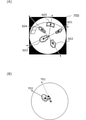
図7Aおよび図7Bは、動体の長さを算出する第2の例を説明する図である。図7Aの画像700は、S102で検知された動体を含む動体領域601~動体領域605を示す。撮像画像の中心は、×印で示される。画像700は、動体領域の重心の座標(以下、重心座標と称する)を星印で示す。
人体判定部12は、重心座標と中心座標とを通る直線が動体領域の輪郭と交わる2点間の距離を、動体の長さ(人体の身長)として算出することができる。第2の例では、人が手を伸ばしている場合でも、人体判定部12は、人体の身長をより精度良く算出することができる。
例えば、図7Bに示すように、手の先端が撮像画像の中心に最も近い場合、第1の例による方法では、手の先端が足元であると誤認識される可能性がある。この場合、中心座標と手の先端の座標とを結ぶ直線は、点線701で示すように、人体の頭頂部を通らない可能性がある。
これに対し、動体領域の重心は、人が手を伸ばしている状態であっても、手および腕の部分は胴体部分よりも細いため、通常胴体部分に存在する。この場合、中心座標と動体領域の重心座標とを結ぶ直線702は、人体の頭頂部を通る。したがって、人体判定部12は、動体領域の重心を用いた第2の例による方法では、人がどのような姿勢であるかに関わらず、精度良く人体の身長を算出することができる。
図4のS104では、人体判定部12は、S103で取得した動体の長さを、撮像画像内での動体の位置に対応して予め設定された閾値の範囲と比較することにより、動体が人体であるか否かを判定する。ここで、図8から図10を参照して、動体が人体であるか否かを判定するための閾値の範囲について説明する。
図8を参照して、魚眼カメラによる撮像画像に写る人体の長さについて説明する。図8は、中心からの距離に応じた人体の長さを示すグラフである。横軸は、撮像画像の中心からの距離である。中心から動体までの距離は、例えば動体領域の重心と撮像画像の中心との距離とすることができる。縦軸は、撮像画像内での人体の長さ(身長)である。
天井に設置された魚眼カメラの真下に立った人体は、足元と頭頂部とが撮像範囲の中心に位置し、撮像画像中の人体の長さは0となる。人体が撮像範囲の中心から離れるにしたがって、人体の長さは大きくなっていく。図8に示す例では、人体の中心からの距離がrを超えると、人体の長さは小さくなっていく。このように、魚眼カメラによる撮像画像では、人体の長さは、中心から離れるにしたがって一旦大きくなるが、中心からの距離がある値を超えると徐々に小さくなるという傾向がある。
図9Aおよび図9Bを参照して、撮像画像内での動体の位置に対応して予め設定される、人体の長さの閾値の範囲について説明する。図9Aおよび図9Bは、撮像範囲の領域ごとに設定される閾値の例を示す図である。図9Aの例に示す撮像範囲は、魚眼カメラによる全天球の撮像範囲を平面展開した例である。撮像範囲は、複数の領域に分割され、中心からの距離に応じてグループ1からグループ5に分類される。各グループに対し、想定される人体の長さの範囲が設定される。
図9Aに示す閾値の範囲は、高さ3mの位置に魚眼カメラを設定して撮影した1600×1200ピクセル(px)の画像で、人体の長さを計測したデータに基づいて設定された閾値の例である。
撮像範囲の中心にあるグループ1の領域では、人体の長さは、0px~100pxであると想定される。グループ1の領域に隣接するグループ2の領域では、人体の長さは、グループ1よりも大きく100px~200pxであると想定される。グループ2の領域に隣接し、さらに外側にあるグループ3の領域では、人体の長さは、グループ2よりも大きく200px~300pxであると想定される。
人体の長さは、グループ3の領域を境に小さくなっていく。グループ3の領域に隣接し、さらに外側にあるグループ4の領域では、人体の長さは、グループ3よりも小さく100px~200pxであると想定される。グループ4の領域に隣接し、さらに外側にあるグループ5の領域では、人体の長さは、グループ4よりも小さく10px~100pxであると想定される。
このように、撮像範囲は、複数に分割され、それぞれの領域で想定される人体の長さの情報が、カメラ10の設置位置および撮像画像の画素数等に応じて予め設定される。設定された人体の長さ(閾値の範囲)の情報は、判定情報データベース15に予め格納される。人体判定部12は、判定情報データベース15に格納された閾値の範囲の情報と、S103で取得した動体の長さとを比較することにより、検知された動体が人体であるか否かを判定することができる。
なお、撮像範囲内に人体より大きい物体がない場合には、各グループに対する閾値の範囲は、上限値を設定しないようにしてもよい。この場合、人体判定部12は、図9Aに例示する閾値の範囲の下限値より大きい動体を、人体であると判定することができる。
また、図9Aは、撮像範囲を矩形として複数に分割し、それぞれの領域に閾値の範囲を設定する例を示すが、これに限られない。図9Bに示すように、円形で表された撮像範囲を複数の同心円で分割し、それぞれの領域で人体の長さについての閾値の範囲が設定されるようにしてもよい。
図10を参照して、図9Aで説明した閾値の範囲を用いて、動体が人体であるか否かを判定する方法について説明する。図10は、動体が人体か否かの判定例を示す図である。人体判定部12は、図6の画像600Cで説明したように、検知した動体領域について、足元座標および頭頂部座標を取得して動体の長さを算出する。
また、人体判定部12は、動体領域が撮像範囲内のどのグループの領域に属するかを判定する。例えば、人体判定部12は、動体領域の頭頂部座標に基づいて、どのグループの領域に属するかを決定することができる。なお、人体判定部12は、頭頂部座標に限られず、足元座標、重心座標、足元座標と頭頂部座標との中点等の位置に基づいて、動体がどのグループの領域に属するかを決定してもよい。
人体判定部12は、動体領域が属するグループの閾値の範囲を判定情報データベース15から取得する。人体判定部12は、S103で算出した動体の長さを、判定情報データベース15から取得した閾値の範囲と比較する。人体判定部12は、動体の長さが閾値の範囲内である場合には、検知した動体が人体であると判定する。
図10の例では、画像600Cの動体領域605は、算出した動体の長さが閾値の範囲に含まれず、人体でないと判定される。画像1000は、動体領域605が人体と判定されなかったことを×印によって示している。また、画像1000は、動体領域601~動体領域604を矩形で囲み、これらの動体領域が人体であると判定されたことを示す。
図4のS104で、検知された動体が人体であると判定された場合(S104:Yes)、処理はS105に進む。検知された動体が人体であると判定されなかった場合(S104:No)、処理はS106に進む。
S105では、人体検出部13は、S104で人体であると判定された動体領域から人体を認識し検出する。人体検出部13は、一般的な物体認識のアルゴリズムを用いて、人体を検出することができる。
ここで、図11Aおよび図11Bを参照し、CNNを使用して動体領域から人体を検出する方法について説明する。図11Aは、S102で複数フレーム間の動体差分から動体を検知した場合の例を示す。人体検出部13は、動体差分から検知した動体領域をそのままCNNに入力することで人体を検出することができる。
ただし、動体差分により動体を検知する場合、検知される動体領域は、複数フレーム分の領域から検知されるため、人体は、図11Aに示すように実際よりも大きく検出される場合がある。そこで、人体検出部13は、図11Bに示すように、動体領域内でウィンドウを順にあてて得られる分割領域をCNNに入力することで、人体を検出するようにしてもよい。ウィンドウによって動体領域をサーチすることにより、人体検出部13は、人体の長さに合った精度の良い検出をすることができる。
なお、人体検出部13は、HoGまたはHaar-likeなどの画像特徴とブースティングとを組み合わせた識別器によって動体領域から人体の認識を行ってもよい。この場合も、動体領域全体に対して人体か否かの判定を行ってもよいし、図11Bに示したものと同じように、ウィンドウによって動体領域をサーチすることにより、動体領域内に含まれる任意の長さの人体を検出・認識するようにしてもよい。
図4のステップS106では、人体判定部12は、S102で検知した動体のうち、人体であるか否かの判定をしていない他の動体があるか否かを判定する。未判定の他の動体がある場合(S106:Yes)、処理はS103に戻る。未判定の他の動体がない場合(S106:No)、図4に示す人体検出処理は終了する。
人体検出処理が終了すると、出力部14は、撮像画像に対して、検出した人体を示す矩形等を重畳表示して、ディスプレイ等に出力する。
(作用効果)
上記の実施形態において、情報処理装置1は、撮像画像から動体を検知し、検知した動体が人体であるか否かを判定する。情報処理装置1は、動体が人体であると判定された場合に、検知した動体を含む動体領域から、ディープラーニング等の手法により人体を検出する。このように、情報処理装置1は、人体を検出する対象となる領域を、人体であると判定された動体領域に限定することで、ディープラーニング等による人体認識の負荷を軽減し、人体をリアルタイムで精度良く検出することができる。
上記の実施形態において、情報処理装置1は、撮像画像から動体を検知し、検知した動体が人体であるか否かを判定する。情報処理装置1は、動体が人体であると判定された場合に、検知した動体を含む動体領域から、ディープラーニング等の手法により人体を検出する。このように、情報処理装置1は、人体を検出する対象となる領域を、人体であると判定された動体領域に限定することで、ディープラーニング等による人体認識の負荷を軽減し、人体をリアルタイムで精度良く検出することができる。
また、情報処理装置1は、検知した動体が人体であるか否かを判定する際、動体の長さを、撮像画像内での動体の位置に応じて予め設定された閾値の範囲と比較する。魚眼カメラで撮影された画像では、撮影された人体は、撮像画像内の位置によって歪みが生じる。撮像画像内の位置に応じて想定される人体の長さが異なるため、人体であるか否か判定するための閾値の範囲は、撮像画像内の位置に応じた範囲に設定される。このように、魚眼カメラによる撮像画像の特性を考慮して、撮像画像内の位置または領域に応じた閾値の範囲が設定されるため、情報処理装置1は、人体であるか否かを精度よく判定することができる。
<その他>
上記実施形態は、本発明の構成例を例示的に説明するものに過ぎない。本発明は上記の具体的な形態には限定されることはなく、その技術的思想の範囲内で種々の変形が可能である。
上記実施形態は、本発明の構成例を例示的に説明するものに過ぎない。本発明は上記の具体的な形態には限定されることはなく、その技術的思想の範囲内で種々の変形が可能である。
上記の実施形態では、人体であるか否か判定するための閾値の範囲は、撮像範囲を複数の領域に分割し、領域ごとに予め設定する例を示したが、これに限られない。例えば、人体であるか否か判定するための閾値の範囲は、撮像画像の中心から動体領域の重心までの距離に応じて、所定の計算式により算出されるようにしてもよい。
また、人体であるか否か判定するための閾値の範囲は、主な撮影対象となる人体の性別または年齢層に応じて異なる値の範囲が設定されてもよい。
<付記1>
(1)魚眼カメラにより撮影された撮像画像から動体を検知する動体検知部(11)と、
前記動体を含む動体領域の輪郭上の所定の2点間の距離を、前記撮像画像内での前記動体の位置で計測された人体の身長に基づいて設定された閾値の範囲と比較することにより、前記動体が人体であるか否かを判定する人体判定部(12)と、
前記人体判定部が人体であると判定した前記動体を含む前記動体領域から人体を検出する人体検出部(13)と、
を備える情報処理装置(1)。
(1)魚眼カメラにより撮影された撮像画像から動体を検知する動体検知部(11)と、
前記動体を含む動体領域の輪郭上の所定の2点間の距離を、前記撮像画像内での前記動体の位置で計測された人体の身長に基づいて設定された閾値の範囲と比較することにより、前記動体が人体であるか否かを判定する人体判定部(12)と、
前記人体判定部が人体であると判定した前記動体を含む前記動体領域から人体を検出する人体検出部(13)と、
を備える情報処理装置(1)。
(2)コンピュータが、
魚眼カメラにより撮影された撮像画像から動体を検知する動体検知ステップ(S102)と、
前記動体を含む動体領域の輪郭上の所定の2点間の距離を、前記撮像画像内での前記動体の位置で計測された人体の身長に基づいて設定された閾値の範囲と比較することにより、前記動体が人体であるか否かを判定する人体判定ステップ(S103、S104)と、
前記人体判定ステップで人体であると判定した前記動体を含む前記動体領域から人体を検出する人体検出部ステップ(S105)と、
を含む情報処理方法。
魚眼カメラにより撮影された撮像画像から動体を検知する動体検知ステップ(S102)と、
前記動体を含む動体領域の輪郭上の所定の2点間の距離を、前記撮像画像内での前記動体の位置で計測された人体の身長に基づいて設定された閾値の範囲と比較することにより、前記動体が人体であるか否かを判定する人体判定ステップ(S103、S104)と、
前記人体判定ステップで人体であると判定した前記動体を含む前記動体領域から人体を検出する人体検出部ステップ(S105)と、
を含む情報処理方法。
1:情報処理装置、10:カメラ、11:動体検知部、12:人体判定部、13:人体検出部、14:出力部、15:判定情報データベース
Claims (10)
- 魚眼カメラにより撮影された撮像画像から動体を検知する動体検知部と、
前記動体を含む動体領域の輪郭上の所定の2点間の距離を、前記撮像画像内での前記動体の位置で計測された人体の身長に基づいて設定された閾値の範囲と比較することにより、前記動体が人体であるか否かを判定する人体判定部と、
前記人体判定部が人体であると判定した前記動体を含む前記動体領域から人体を検出する人体検出部と、
を備える情報処理装置。 - 前記動体を含む動体領域の輪郭上の所定の2点間の距離は、前記動体領域で前記撮像画像の中心座標から最も近い点または最も遠い点である第1座標と、前記中心座標および前記第1座標を通る直線と前記動体領域の輪郭との交点であって前記第1座標とは異なる第2座標との距離である
請求項1に記載の情報処理装置。 - 前記動体を含む動体領域の輪郭上の所定の2点間の距離は、前記動体領域の重心座標と前記撮像画像の中心座標とを通る直線が、前記動体領域の輪郭と交わる2点間の距離である
請求項1に記載の情報処理装置。 - 前記閾値の範囲は、前記撮像画像を複数に分割した領域ごとに設定される
請求項1から3のいずれか1項に記載の情報処理装置。 - 前記動体検知部は、背景差分法、またはフレーム間差分法により、前記動体を検知する請求項1から4のいずれか1項に記載の情報処理装置。
- 前記動体検知部は、前記撮像画像の連続するフレーム内で共通して写る物体の動作および移動方向に基づいて、前記動体を検知する
請求項1から4のいずれか1項に記載の情報処理装置。 - 前記人体検出部が検出した人体の情報を出力する出力部をさらに備える
請求項1から6のいずれか1項に記載の情報処理装置。 - 前記撮像画像を撮影する撮像部をさらに備える
請求項1から7のいずれか1項に記載の情報処理装置。 - コンピュータが、
魚眼カメラにより撮影された撮像画像から動体を検知する動体検知ステップと、
前記動体を含む動体領域の輪郭上の所定の2点間の距離を、前記撮像画像内での前記動体の位置で計測された人体の身長に基づいて設定された閾値の範囲と比較することにより、前記動体が人体であるか否かを判定する人体判定ステップと、
前記人体判定ステップで人体であると判定した前記動体を含む前記動体領域から人体を検出する人体検出部ステップと、
を含む情報処理方法。 - 請求項9に記載の方法の各ステップをコンピュータに実行させるためのプログラム。
Priority Applications (3)
| Application Number | Priority Date | Filing Date | Title |
|---|---|---|---|
| DE112021003775.7T DE112021003775T5 (de) | 2020-07-15 | 2021-06-17 | Informationsverarbeitungsvorrichtung und informationsverarbeitungsverfahren |
| CN202180047053.7A CN115803780A (zh) | 2020-07-15 | 2021-06-17 | 信息处理装置以及信息处理方法 |
| US18/003,598 US12272078B2 (en) | 2020-07-15 | 2021-06-17 | Information processing device and information processing method |
Applications Claiming Priority (2)
| Application Number | Priority Date | Filing Date | Title |
|---|---|---|---|
| JP2020121087A JP7419999B2 (ja) | 2020-07-15 | 2020-07-15 | 情報処理装置および情報処理方法 |
| JP2020-121087 | 2020-07-15 |
Publications (1)
| Publication Number | Publication Date |
|---|---|
| WO2022014252A1 true WO2022014252A1 (ja) | 2022-01-20 |
Family
ID=79555408
Family Applications (1)
| Application Number | Title | Priority Date | Filing Date |
|---|---|---|---|
| PCT/JP2021/023104 Ceased WO2022014252A1 (ja) | 2020-07-15 | 2021-06-17 | 情報処理装置および情報処理方法 |
Country Status (5)
| Country | Link |
|---|---|
| US (1) | US12272078B2 (ja) |
| JP (1) | JP7419999B2 (ja) |
| CN (1) | CN115803780A (ja) |
| DE (1) | DE112021003775T5 (ja) |
| WO (1) | WO2022014252A1 (ja) |
Families Citing this family (5)
| Publication number | Priority date | Publication date | Assignee | Title |
|---|---|---|---|---|
| JP2022102947A (ja) * | 2020-12-25 | 2022-07-07 | 富士通株式会社 | 検知プログラム、検知方法、および検知装置 |
| JP7652626B2 (ja) * | 2021-06-01 | 2025-03-27 | キヤノン株式会社 | 情報処理装置、情報処理方法、及びプログラム |
| JP2023115774A (ja) | 2022-02-08 | 2023-08-21 | 株式会社デンソー | 回転電機の固定子 |
| US12356076B2 (en) * | 2022-05-24 | 2025-07-08 | Canon Kabushiki Kaisha | Image capture control device, image capture device, image capture control method, and non-transitory computer-readable storage medium |
| JP2024008196A (ja) * | 2022-07-07 | 2024-01-19 | オムロン株式会社 | 情報処理装置および情報処理方法 |
Citations (3)
| Publication number | Priority date | Publication date | Assignee | Title |
|---|---|---|---|---|
| JP2015187880A (ja) * | 2015-05-25 | 2015-10-29 | 株式会社ニコン | 検出装置 |
| JP2019159739A (ja) * | 2018-03-13 | 2019-09-19 | キヤノン株式会社 | 画像処理装置、画像処理方法およびプログラム |
| JP2020086844A (ja) * | 2018-11-22 | 2020-06-04 | キヤノン株式会社 | 画像処理装置、画像処理方法、およびプログラム |
Family Cites Families (19)
| Publication number | Priority date | Publication date | Assignee | Title |
|---|---|---|---|---|
| JP4644992B2 (ja) * | 2001-08-10 | 2011-03-09 | パナソニック電工株式会社 | 距離画像を用いた人体検知方法 |
| US7876361B2 (en) * | 2005-07-26 | 2011-01-25 | Honeywell International Inc. | Size calibration and mapping in overhead camera view |
| US7884849B2 (en) * | 2005-09-26 | 2011-02-08 | Objectvideo, Inc. | Video surveillance system with omni-directional camera |
| CN101866425A (zh) * | 2010-06-02 | 2010-10-20 | 北京交通大学 | 基于鱼眼摄像头的人体检测方法 |
| CN103221984B (zh) * | 2010-11-19 | 2016-10-05 | 株式会社尼康 | 引导装置、检测装置以及姿势状态判定装置 |
| US20140193034A1 (en) * | 2011-06-27 | 2014-07-10 | Nec Corporation | Object detection device, object detection method and object detection program |
| JP5919538B2 (ja) * | 2012-06-15 | 2016-05-18 | パナソニックIpマネジメント株式会社 | 物体検出装置及び物体検出方法 |
| KR101758684B1 (ko) * | 2012-07-23 | 2017-07-14 | 한화테크윈 주식회사 | 객체 추적 장치 및 방법 |
| CN106104631B (zh) * | 2014-03-11 | 2019-03-01 | 三菱电机株式会社 | 人物检测装置及人物检测方法 |
| JP6396838B2 (ja) * | 2015-03-31 | 2018-09-26 | 株式会社デンソー | 車両制御装置、及び車両制御方法 |
| JP6953818B2 (ja) * | 2016-11-14 | 2021-10-27 | 株式会社アイシン | 動作判定装置 |
| JP6906973B2 (ja) | 2017-02-09 | 2021-07-21 | グローリー株式会社 | 顔検出装置、顔検出方法、顔検出プログラム、及び対象物検出装置 |
| JPWO2018230104A1 (ja) * | 2017-06-16 | 2020-04-16 | コニカミノルタ株式会社 | 被監視者監視支援システムの中央処理装置および中央処理方法ならびに被監視者監視支援システム |
| US10373322B1 (en) * | 2018-07-16 | 2019-08-06 | Accel Robotics Corporation | Autonomous store system that analyzes camera images to track people and their interactions with items |
| JP7101080B2 (ja) * | 2018-08-13 | 2022-07-14 | セコム株式会社 | 画像処理装置 |
| JP7338174B2 (ja) * | 2019-03-06 | 2023-09-05 | オムロン株式会社 | 物体検出装置および物体検出方法 |
| JP7192582B2 (ja) * | 2019-03-11 | 2022-12-20 | オムロン株式会社 | 物体追跡装置および物体追跡方法 |
| WO2021050369A1 (en) * | 2019-09-10 | 2021-03-18 | The Regents Of The University Of California | Autonomous comfort systems |
| JP7354767B2 (ja) * | 2019-10-29 | 2023-10-03 | オムロン株式会社 | 物体追跡装置および物体追跡方法 |
-
2020
- 2020-07-15 JP JP2020121087A patent/JP7419999B2/ja active Active
-
2021
- 2021-06-17 CN CN202180047053.7A patent/CN115803780A/zh active Pending
- 2021-06-17 DE DE112021003775.7T patent/DE112021003775T5/de active Pending
- 2021-06-17 WO PCT/JP2021/023104 patent/WO2022014252A1/ja not_active Ceased
- 2021-06-17 US US18/003,598 patent/US12272078B2/en active Active
Patent Citations (3)
| Publication number | Priority date | Publication date | Assignee | Title |
|---|---|---|---|---|
| JP2015187880A (ja) * | 2015-05-25 | 2015-10-29 | 株式会社ニコン | 検出装置 |
| JP2019159739A (ja) * | 2018-03-13 | 2019-09-19 | キヤノン株式会社 | 画像処理装置、画像処理方法およびプログラム |
| JP2020086844A (ja) * | 2018-11-22 | 2020-06-04 | キヤノン株式会社 | 画像処理装置、画像処理方法、およびプログラム |
Also Published As
| Publication number | Publication date |
|---|---|
| DE112021003775T5 (de) | 2023-06-01 |
| US20230237676A1 (en) | 2023-07-27 |
| JP7419999B2 (ja) | 2024-01-23 |
| US12272078B2 (en) | 2025-04-08 |
| JP2022018173A (ja) | 2022-01-27 |
| CN115803780A (zh) | 2023-03-14 |
Similar Documents
| Publication | Publication Date | Title |
|---|---|---|
| WO2022014252A1 (ja) | 情報処理装置および情報処理方法 | |
| CN114616591B (zh) | 物体跟踪装置以及物体跟踪方法 | |
| US20180165828A1 (en) | Object Recognition Device and Object Recognition System | |
| CN103996019B (zh) | 用于检测和跟踪一个物体上多个部位的系统和方法 | |
| JP7188240B2 (ja) | 人検出装置および人検出方法 | |
| JP7192582B2 (ja) | 物体追跡装置および物体追跡方法 | |
| JP7272024B2 (ja) | 物体追跡装置、監視システムおよび物体追跡方法 | |
| JP6579950B2 (ja) | カメラの撮影画像に映る人物を検出する画像解析装置、プログラム及び方法 | |
| JP2020182146A (ja) | 監視装置、及び、監視方法 | |
| US10496874B2 (en) | Facial detection device, facial detection system provided with same, and facial detection method | |
| KR20230099225A (ko) | 영상 내 건설 작업자의 안전 상태를 모니터링하는 장치 및 이의 동작 방법 | |
| US20240249427A1 (en) | Position measurement system | |
| CN113168694B (zh) | 人检测装置以及人检测方法 | |
| WO2021095095A1 (ja) | カメラ校正装置、カメラ校正方法及びカメラ校正プログラムが格納された非一時的なコンピュータ可読媒体 | |
| WO2020261403A1 (ja) | 身長推定装置、身長推定方法及びプログラムが格納された非一時的なコンピュータ可読媒体 | |
| US20180082129A1 (en) | Information processing apparatus, detection system, and information processing method | |
| WO2021140844A1 (ja) | 人体検出装置および人体検出方法 | |
| JP2020113950A (ja) | 情報処理装置、プログラム、被画像認識用マーカセット | |
| JP2022110441A (ja) | 情報処理装置および情報処理方法 | |
| CN119648728B (zh) | 基于三维激光点云数据引导的红外图像边缘检测方法 | |
| KR101765568B1 (ko) | 보행자 인식 시스템 및 그 제어 방법 | |
| JP2020113951A (ja) | 情報処理装置、プログラム、被画像認識用マーカ | |
| CN108717532B (zh) | 一种人机交互效果良好的智能机器人 | |
| CN116755562A (zh) | 一种避障方法、装置、介质及ar/vr设备 | |
| CN121999539A (zh) | 多视角协同的作业行为风险评估方法及其系统 |
Legal Events
| Date | Code | Title | Description |
|---|---|---|---|
| 121 | Ep: the epo has been informed by wipo that ep was designated in this application |
Ref document number: 21841512 Country of ref document: EP Kind code of ref document: A1 |
|
| 122 | Ep: pct application non-entry in european phase |
Ref document number: 21841512 Country of ref document: EP Kind code of ref document: A1 |
|
| WWG | Wipo information: grant in national office |
Ref document number: 18003598 Country of ref document: US |