WO2022018918A1 - Dispositif d'acquisition d'informations de ligne de chemin de fer et procédé d'acquisition d'informations de ligne de chemin de fer - Google Patents
Dispositif d'acquisition d'informations de ligne de chemin de fer et procédé d'acquisition d'informations de ligne de chemin de fer Download PDFInfo
- Publication number
- WO2022018918A1 WO2022018918A1 PCT/JP2021/015949 JP2021015949W WO2022018918A1 WO 2022018918 A1 WO2022018918 A1 WO 2022018918A1 JP 2021015949 W JP2021015949 W JP 2021015949W WO 2022018918 A1 WO2022018918 A1 WO 2022018918A1
- Authority
- WO
- WIPO (PCT)
- Prior art keywords
- line
- image
- unit
- coordinate system
- track
- Prior art date
- Legal status (The legal status is an assumption and is not a legal conclusion. Google has not performed a legal analysis and makes no representation as to the accuracy of the status listed.)
- Ceased
Links
Images











Classifications
-
- B—PERFORMING OPERATIONS; TRANSPORTING
- B61—RAILWAYS
- B61L—GUIDING RAILWAY TRAFFIC; ENSURING THE SAFETY OF RAILWAY TRAFFIC
- B61L25/00—Recording or indicating positions or identities of vehicles or trains or setting of track apparatus
- B61L25/02—Indicating or recording positions or identities of vehicles or trains
- B61L25/025—Absolute localisation, e.g. providing geodetic coordinates
-
- B—PERFORMING OPERATIONS; TRANSPORTING
- B61—RAILWAYS
- B61L—GUIDING RAILWAY TRAFFIC; ENSURING THE SAFETY OF RAILWAY TRAFFIC
- B61L23/00—Control, warning or like safety means along the route or between vehicles or trains
- B61L23/04—Control, warning or like safety means along the route or between vehicles or trains for monitoring the mechanical state of the route
- B61L23/041—Obstacle detection
-
- G—PHYSICS
- G06—COMPUTING OR CALCULATING; COUNTING
- G06V—IMAGE OR VIDEO RECOGNITION OR UNDERSTANDING
- G06V20/00—Scenes; Scene-specific elements
- G06V20/50—Context or environment of the image
- G06V20/56—Context or environment of the image exterior to a vehicle by using sensors mounted on the vehicle
- G06V20/588—Recognition of the road, e.g. of lane markings; Recognition of the vehicle driving pattern in relation to the road
-
- G—PHYSICS
- G06—COMPUTING OR CALCULATING; COUNTING
- G06V—IMAGE OR VIDEO RECOGNITION OR UNDERSTANDING
- G06V2201/00—Indexing scheme relating to image or video recognition or understanding
- G06V2201/10—Recognition assisted with metadata
Definitions
- An embodiment of the present invention relates to a railway track information acquisition device and a railway track information acquisition method.
- a monitoring method for monitoring obstacles ahead by using an image captured by a camera mounted on a railroad vehicle is generally known.
- it is determined whether or not an object in front of the object is an obstacle that may collide with the object. Therefore, it is necessary to perform a process of detecting a track to be traveled in the image. Since railroad vehicles have a long braking distance until they stop, it is required to detect a farther track with high accuracy and high speed.
- a railway track information acquisition device capable of detecting track position information with higher accuracy, and a railway track information acquisition method.
- the railway track information acquisition device includes an image acquisition unit, a track information acquisition unit, a conversion unit, and a control unit.
- the image acquisition unit acquires a captured image of the traveling direction of the railway vehicle.
- the track information acquisition unit acquires the position information of the first track in the direction in which the railway vehicle travels, based on the position of the railway vehicle.
- the conversion unit converts the captured image and the first line into a common coordinate system.
- the control unit acquires the position information of the first line corresponding to the second line in the captured image in the common coordinate system.
- the image pickup device 10 can continuously capture R, G, and B images as an image pickup moving image.
- the image pickup device 10 is fixed in front of, for example, a railroad vehicle 5. Therefore, each image constituting the captured moving image captured while the railway vehicle 5 is traveling on the railroad track is, for example, an image having the same angle and the same imaging magnification when captured at the same position. These images are stored in the storage unit 204 described later.
- the notification unit 50 displays various information together with the image captured by the image pickup device 10. Further, the notification unit 50 notifies, for example, information about the obstacle detected by the obstacle detection device 40 to, for example, the central control room.
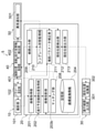
- the image acquisition unit 201 of the railway track information acquisition device 20 acquires images captured in the traveling direction of the railway vehicle 5 in order from the image acquisition unit 101.
- the planned traveling track position acquisition unit 202 acquires the position information of the track in the direction in which the railway vehicle 5 travels from the traveling position information collecting device 30.
- the railway track information acquisition device 20 includes, for example, a CPU (Central Processing Unit).
- the storage unit 204 stores various programs for executing the monitoring operation. As a result, the railway line information acquisition device 20 constitutes each unit by, for example, executing a program stored in the storage unit 204.
- the traveling track output unit 302 outputs information on the track position in a predetermined range in the traveling direction of the railway vehicle 5 based on the current position of the railway vehicle 5 acquired by the current position collecting unit 301.
- the predetermined range is, for example, 50 to 200 meters ahead in the direction of travel.
- the range of 50 to 200 meters is an example and is not limited to this.
- the track position / image acquisition unit 401 of the obstacle detection device 40 acquires the image captured by the image pickup unit 101 and the position information of the track in the captured image contrasted by the matching unit 205.
- Homography matrices Hn and T are associated with and stored in each setting point (PnL, PnR), as will be described later.
- the homography matrix H of the present embodiment is a matrix that associates the geographic coordinate system (X, Y) with the camera coordinate system (x, y) of the imaging unit 101.
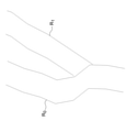
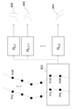
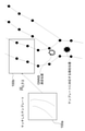
- FIG. 5 is a diagram schematically showing the positions where the setting points (PnL, PnR) are set on the lines R 0 and R 1. In this way, the latitude and longitude are associated with the set points (PnL, PnR) for the entire range of the railroad track on which the railroad vehicle 5 travels.
- the line information indicated by the camera coordinates (x, y) in the image 808 is a homography matrix of the line information indicated by the geographic coordinate system (X, Y) in the image 802 corresponding to the setting point (P0L, P0R).
- the line information converted into camera coordinates by H0 and T corresponds to the line information converted into camera coordinates by H0 and T. That is, the line information indicated by the camera coordinates (x, y) in the image 808 coincides with the position coordinates of the camera coordinate system of the line in the image captured by the image pickup unit 101 at the position indicated by T in the region corresponding to the image 802. do.
- the matching unit 205 detects a line from the captured image 902 using, for example, templates (0, T) to (n, T) generated by coordinate transformation using the homography matrix H shown in FIG.
- the matching unit 205 expresses, for example, a line in the captured image 902 as a line component connecting a short straight line and a curved line segment. Then, the matching unit 205 selects the template that best matches the line component and the template (0, T) to (n, T).
- the line output unit 206 outputs the position information of the line in the most matching template as the line position information in the captured image 902.
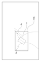
- FIG. 9 is a diagram showing a processing example of the line output unit 206.
- Images 904b to 908b show templates that best match the captured images captured at time T1 to T3, respectively.
- the image 904b corresponds to the set point (P0L, P0r) template the line information 904a corresponding to the generated converted by homography matrix H 0,0. That is, the line output unit 206 outputs the line information shown in the image 904b converted into the camera coordinate system (x, y) for the captured image captured at time T1.
- the image 906b corresponds to a template generated by converting the line information 906a corresponding to the setting points (P3L, P3R) with the homography matrices H3 and T-1.
- the parameter correction unit 210 outputs a signal including parameter information to the parameter setting unit 102 based on the current position of the railway vehicle 5 output by the current position detection unit 207.
- the storage unit 204 also stores tunnel position information in association with the track information.
- the parameter correction unit 210 determines whether or not the tunnel is imaged in the image captured by the image pickup unit 101 with respect to the current position of the railway vehicle 5.
- the parameter correction unit 210 outputs a parameter for lowering the exposure to the parameter setting unit 102. More specifically, the parameter correction unit 210 corrects the contrast of the adjustment area A130 in the tunnel to a parameter having a predetermined contrast as an evaluation value.
- the parameter correction unit 210 outputs a signal including parameter information to the parameter setting unit 102 based on the current position of the railway vehicle 5 output by the current position detection unit 207 (step S15), and ends the process.
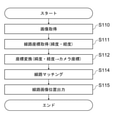
- FIG. 15 is a flowchart showing a detailed processing flow of the line detection process.
- the image acquisition unit 201 acquires an image captured in the traveling direction of the railway vehicle 5 from the image acquisition unit 101. (Step S110).
- the line output unit 206 outputs the position information of the line that matches the line in the captured image controlled by the matching unit 205 (step S115), and ends the process.
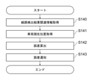
- the traveling position information collecting device 30 calculates an error between the current position of the railway vehicle 5 output by the current position detection unit 207 and the current position of the railway vehicle 5 by GNSS (step S142). Then, when the error exceeds a predetermined value, the traveling position information collecting device 30 corrects the output value based on the current position of the railway vehicle 5 output by the current position detection unit 207, and corrects the correction information via the notification unit 50. Notify (step S143) and end the process.
- FIG. 17 is a flowchart showing a detailed processing flow of the shooting parameter correction processing. Here, an example of parameter correction using the contrast in the captured image as an evaluation value will be described.
- the parameter correction unit 210 acquires the information of the brightness adjustment area A130 associated with the position information of the tunnel (step S151).
- the line coordinate conversion unit 203 has acquired the position information of the line of the geographic coordinate system in the predetermined range and the captured image of the camera coordinate system in which the predetermined range is captured. Is converted into a common coordinate system, and the matching unit 205 acquires the position information of the line of the geographic coordinate system corresponding to the line in the captured image.
- This makes it possible to acquire the position information of the line in the captured image corresponding to the position information of the line of the geographic coordinate system acquired in advance. In this way, even if the line in the captured image of the camera coordinate system is not clearly captured, by converting it to a common coordinate system, the position information of the line in the geographic coordinate system that best matches the line in the captured image as a whole. Can be acquired, and the position information of the track in the captured image can be acquired more accurately.
- the railroad track acquisition system 1 according to the second embodiment is different from the railroad track acquisition system 1 according to the first embodiment in that the image projection unit 203b converts the captured image of the camera coordinate system into the geographic coordinate system. ..
- the differences from the railroad track acquisition system 1 according to the first embodiment will be described.
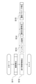
- FIG. 18 is a block diagram showing the configuration of the railroad track acquisition system 1 according to the second embodiment.
- the image projection unit 203b converts the captured image of the camera coordinate system into the geographic coordinate system.
- the image projection unit 203b according to the present embodiment corresponds to the conversion unit.
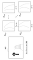
- FIG. 19 is a diagram showing inverse transformation matrices RH 0, 0 to RH 0, T of homography matrices H 0, 0 to H 0, T corresponding to setting points (P0L, P0R).
- the image 192 of the camera coordinate system is an image taken at a reference position of a setting point (P0L, P0R). Therefore, when the image projection unit 203b reversely changes the image 192 with the inverse transformation matrix RH 0 , 0, it matches the image 194 of the geographic coordinate system corresponding to the set point (P0L, P0R).
- the images 196 and 198 of the line information of the geographic coordinate system that do not actually exist are generated.
- the inverse transformation matrix RH 0 that is inversely converted to the matched image. , 0 indicates that the region for image 194 was imaged from a distance corresponding to 0.
- FIG. 20 is a diagram showing an example of an inverse template generated by the image projection unit 203b by performing inverse coordinate conversion.
- An image obtained by inversely transforming the line information of the image 902 of the camera coordinate system by the inverse transformation matrix RH 0, 0 to RH n, T of the homography matrix H 0, 0 to H n, T is shown, respectively.
- the line information converted into the geographic coordinate system (X, Y) by the inverse transformation matrix RH n, T of the homography matrix is referred to as an inverse template R (n, T).
- the image projection unit 203b considers the range in which an error occurs in the position of the railroad vehicle 5, and considers the reverse template R for the setting points (P0L, P0R) to (PnL, PnR) in the range where the image of the railroad vehicle 5 is possible. (0, T) to R (n, T) are generated.
- the matching unit 205 uses, for example, the inverse templates R (0, T) to R (n, T) generated by inverse coordinate conversion with the inverse transformation matrix RH of the homography matrix shown in FIG. 20, and the setting point (P0L, Select the inverse template that best matches the line information of the geographic coordinate system corresponding to P0R) to (PnL, PnR).
- FIG. 21 is a diagram showing a processing example of the line output unit 206.
- the images 904b to 908b are captured images taken at time T1 to T3, respectively, and the images 904c to 908c show the most matched inverse template.
- the image 904c corresponds to the inverse template generated by converting with the inverse matrix RH 0 , 0 corresponding to the setting point (P0L, P0R). That is, the line output unit 206 outputs the line information of the geographic coordinate system (X, Y) corresponding to the set point (P0L, P0R) to the captured image 904b captured at the time T1.
- the image 906c corresponds to the inverse template generated by conversion with the inverse matrices RH 3 and T-1 corresponding to the setting points (P3L, P3R). That is, the line output unit 206 outputs the geographic coordinate system (X, Y) line information corresponding to the set point (P3L, P3R) to the captured image 906b captured at time T2.
- FIG. 22 is a flowchart showing a detailed processing flow of the current position detection processing according to the second embodiment.
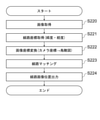
- the image acquisition unit 201 acquires an image captured in the traveling direction of the railway vehicle 5 from the image acquisition unit 101. (Step S220).
- the planned traveling track position acquisition unit 202 acquires the position information of the track in the direction in which the railway vehicle 5 travels from the traveling position information collecting device 30. (Step S221).
- the image projection unit 203b converts the captured image acquired by the image acquisition unit 20 and the position information of the track into a common coordinate system.
- the inverse transformation matrix RH of the homography matrix is used for inverse transformation to the geographic coordinate system.
- the matching unit 205 acquires the position information of the line corresponding to the line in the captured image in the common coordinate system (step S223).
- the line output unit 206 outputs the position information of the line (step S223), and ends the whole process.
- the image projection unit 203b converts the captured image of the camera coordinate system that captures a predetermined range into the geographic coordinate system, and the matching unit 205 corresponds to the line in the captured image. Moreover, the position information of the line in the geographic coordinate system acquired in advance is acquired. This makes it possible to acquire the position information of the line in the captured image corresponding to the position information of the line acquired in advance.
- the railway track acquisition system 1 according to the third embodiment acquires the railway track according to the first embodiment in that the track information of the geographic coordinate system is stored in the coordinates of the three axes (X, Y, Z). Different from system 1.
- the differences from the railroad track acquisition system 1 according to the first embodiment will be described.
- FIG. 23 is a flowchart showing a detailed processing flow of the line detection processing according to the third embodiment.
- the image acquisition unit 201 acquires a stereo image taken in the traveling direction of the railway vehicle 5 from the image acquisition unit 101. (Step S230).
- the planned traveling track position acquisition unit 202 acquires the position information of the track in the direction in which the railway vehicle 5 travels from the traveling position information collecting device 30. (Step S231).
- the line coordinate conversion unit 203 is limited to the position information of the line having the calculated inclination and the inclination within a predetermined range (step S234), and converts the captured image acquired by the image acquisition unit 20 and the position information of the line into a common coordinate system. do. (Step S113).
- the elevation information which is a value in the Z-axis direction, is used to convert to the camera coordinate system in the horizontal plane.
- the image converted by this camera coordinate system is a so-called bird's-eye view.
- the matching unit 205 acquires the position information of the line corresponding to the line in the captured image in the common coordinate system (step S114).
- the position information of the tracks having different inclinations into a bird's-eye view which is a horizontal plane, the influence of the inclination can be suppressed and matching in the matching unit 205 becomes possible with higher accuracy.
- the line output unit 206 outputs the position information of the line that matches the line in the captured image controlled by the matching unit 205 (step S115), and ends the process.
Landscapes
- Engineering & Computer Science (AREA)
- Mechanical Engineering (AREA)
- Physics & Mathematics (AREA)
- General Physics & Mathematics (AREA)
- Multimedia (AREA)
- Theoretical Computer Science (AREA)
- Train Traffic Observation, Control, And Security (AREA)
- Image Analysis (AREA)
- Image Processing (AREA)
Abstract
Un dispositif d'acquisition d'informations de ligne de chemin de fer selon le présent mode de réalisation comprend une unité d'acquisition d'image, une unité d'acquisition d'informations de ligne, une unité de conversion et une unité de contraste. L'unité d'acquisition d'image acquiert une image capturée d'un véhicule ferroviaire dans une direction de déplacement. L'unité d'acquisition d'informations de ligne acquiert, sur la base de l'emplacement d'un véhicule ferroviaire, des informations d'emplacement concernant une première voie ferrée dans la direction de déplacement de véhicule ferroviaire. L'unité de conversion convertit l'image capturée et la première ligne en un système de coordonnées commun. L'unité de contraste acquiert les informations d'emplacement concernant la première ligne à laquelle une seconde ligne dans l'image capturée correspond dans le système de coordonnées commun.
Priority Applications (2)
| Application Number | Priority Date | Filing Date | Title |
|---|---|---|---|
| EP21846756.1A EP4183660A4 (fr) | 2020-07-20 | 2021-04-20 | Dispositif d'acquisition d'informations de ligne de chemin de fer et procédé d'acquisition d'informations de ligne de chemin de fer |
| CN202180039062.1A CN115916623B (zh) | 2020-07-20 | 2021-04-20 | 铁道线路信息取得装置以及铁道线路信息取得方法 |
Applications Claiming Priority (2)
| Application Number | Priority Date | Filing Date | Title |
|---|---|---|---|
| JP2020123798A JP7455690B2 (ja) | 2020-07-20 | 2020-07-20 | 鉄道線路情報取得装置、及び鉄道線路情報取得方法 |
| JP2020-123798 | 2020-07-20 |
Publications (1)
| Publication Number | Publication Date |
|---|---|
| WO2022018918A1 true WO2022018918A1 (fr) | 2022-01-27 |
Family
ID=79728596
Family Applications (1)
| Application Number | Title | Priority Date | Filing Date |
|---|---|---|---|
| PCT/JP2021/015949 Ceased WO2022018918A1 (fr) | 2020-07-20 | 2021-04-20 | Dispositif d'acquisition d'informations de ligne de chemin de fer et procédé d'acquisition d'informations de ligne de chemin de fer |
Country Status (4)
| Country | Link |
|---|---|
| EP (1) | EP4183660A4 (fr) |
| JP (1) | JP7455690B2 (fr) |
| CN (1) | CN115916623B (fr) |
| WO (1) | WO2022018918A1 (fr) |
Cited By (1)
| Publication number | Priority date | Publication date | Assignee | Title |
|---|---|---|---|---|
| EP4286245A1 (fr) * | 2022-06-03 | 2023-12-06 | Kabushiki Kaisha Toshiba | Dispositif de détection d'informations de position |
Families Citing this family (3)
| Publication number | Priority date | Publication date | Assignee | Title |
|---|---|---|---|---|
| JP2024044610A (ja) * | 2022-09-21 | 2024-04-02 | 日本信号株式会社 | 車両安全支援システム |
| JP7815169B2 (ja) * | 2023-03-22 | 2026-02-17 | 株式会社東芝 | 線路情報生成装置、線路情報生成方法およびプログラム |
| KR20250092451A (ko) * | 2023-12-15 | 2025-06-24 | 포스코홀딩스 주식회사 | 장애물 검출 장치 및 그 방법 |
Citations (5)
| Publication number | Priority date | Publication date | Assignee | Title |
|---|---|---|---|---|
| JP2007096510A (ja) * | 2005-09-27 | 2007-04-12 | Omron Corp | 前方撮影装置 |
| JP2016172824A (ja) | 2015-03-17 | 2016-09-29 | 日本化薬株式会社 | ポリイミド樹脂組成物、及びそれを用いた接着フィルム |
| JP2018039288A (ja) * | 2016-09-05 | 2018-03-15 | 株式会社明電舎 | 分岐器進入可否判定装置及び分岐器進入可否判定方法 |
| WO2018101455A1 (fr) * | 2016-12-02 | 2018-06-07 | 東日本旅客鉄道株式会社 | Système et procédé de patrouille d'installation |
| JP2019218022A (ja) | 2018-06-22 | 2019-12-26 | 株式会社東芝 | 線路検出装置 |
Family Cites Families (6)
| Publication number | Priority date | Publication date | Assignee | Title |
|---|---|---|---|---|
| KR20070099310A (ko) * | 2006-04-04 | 2007-10-09 | 주식회사 동진쎄미켐 | 평판 표시 장치의 제조 시스템 |
| JP2008292291A (ja) * | 2007-05-24 | 2008-12-04 | Jr Higashi Nippon Consultants Kk | ナビゲーション装置 |
| CN102673609B (zh) * | 2012-05-21 | 2015-07-08 | 株洲时代电子技术有限公司 | 一种铁路维修作业安全预警系统及其方法 |
| JP2018508418A (ja) * | 2015-01-20 | 2018-03-29 | ソルフィス リサーチ、インコーポレイテッド | リモートセンシング及び車両制御のための実時間マシンビジョン並びに点群分析 |
| EP3048559A1 (fr) * | 2015-01-21 | 2016-07-27 | RindInvest AB | Procédé et système de détection d'une voie ferrée |
| AT518579B1 (de) * | 2016-04-15 | 2019-03-15 | Plasser & Theurer Export Von Bahnbaumaschinen Gmbh | Verfahren und Messsystem zum Erfassen eines Festpunktes neben einem Gleis |
-
2020
- 2020-07-20 JP JP2020123798A patent/JP7455690B2/ja active Active
-
2021
- 2021-04-20 CN CN202180039062.1A patent/CN115916623B/zh active Active
- 2021-04-20 EP EP21846756.1A patent/EP4183660A4/fr active Pending
- 2021-04-20 WO PCT/JP2021/015949 patent/WO2022018918A1/fr not_active Ceased
Patent Citations (5)
| Publication number | Priority date | Publication date | Assignee | Title |
|---|---|---|---|---|
| JP2007096510A (ja) * | 2005-09-27 | 2007-04-12 | Omron Corp | 前方撮影装置 |
| JP2016172824A (ja) | 2015-03-17 | 2016-09-29 | 日本化薬株式会社 | ポリイミド樹脂組成物、及びそれを用いた接着フィルム |
| JP2018039288A (ja) * | 2016-09-05 | 2018-03-15 | 株式会社明電舎 | 分岐器進入可否判定装置及び分岐器進入可否判定方法 |
| WO2018101455A1 (fr) * | 2016-12-02 | 2018-06-07 | 東日本旅客鉄道株式会社 | Système et procédé de patrouille d'installation |
| JP2019218022A (ja) | 2018-06-22 | 2019-12-26 | 株式会社東芝 | 線路検出装置 |
Non-Patent Citations (2)
| Title |
|---|
| "Geometry Constraints-based Visual Rail Track Extraction", CONFERENCE: 2016 12TH WORLD CONGRESS ON INTELLIGENT CONTROL AND AUTOMATION (WCICA |
| See also references of EP4183660A4 |
Cited By (1)
| Publication number | Priority date | Publication date | Assignee | Title |
|---|---|---|---|---|
| EP4286245A1 (fr) * | 2022-06-03 | 2023-12-06 | Kabushiki Kaisha Toshiba | Dispositif de détection d'informations de position |
Also Published As
| Publication number | Publication date |
|---|---|
| JP2022020355A (ja) | 2022-02-01 |
| EP4183660A4 (fr) | 2024-07-31 |
| CN115916623B (zh) | 2026-03-31 |
| CN115916623A (zh) | 2023-04-04 |
| JP7455690B2 (ja) | 2024-03-26 |
| EP4183660A1 (fr) | 2023-05-24 |
Similar Documents
| Publication | Publication Date | Title |
|---|---|---|
| WO2022018918A1 (fr) | Dispositif d'acquisition d'informations de ligne de chemin de fer et procédé d'acquisition d'informations de ligne de chemin de fer | |
| US8452467B2 (en) | System and method for verifying track database information | |
| KR102871296B1 (ko) | 유도로 상의 항공기 포지셔닝 | |
| JP4370869B2 (ja) | 地図データ更新方法および地図データ更新装置 | |
| US8538609B2 (en) | System, method, and computer readable memory medium for verifying track database information | |
| JP2016052849A (ja) | 障害物検出装置及び方法 | |
| JP2021513481A (ja) | 鉄道線路上の関心点または線を位置特定し、鉄道線路上に介入マシンを位置決めし、かつ駆動するための方法 | |
| JP2021512242A5 (fr) | ||
| JP2019188846A (ja) | 物体検知システム | |
| CN113316706A (zh) | 路标位置估计设备和方法以及存储被编程为执行该方法的计算机程序的计算机可读记录介质 | |
| JP2019095228A (ja) | 車輪形状測定方法 | |
| KR102217422B1 (ko) | 운전면허시험 처리 장치 | |
| WO2025251509A1 (fr) | Procédé d'identification d'intrusion d'objet étranger basé sur un système de surveillance de la sécurité de fonctionnement d'un véhicule du génie | |
| Cudrano et al. | Clothoid-based lane-level high-definition maps: Unifying sensing and control models | |
| Wang et al. | An inverse projective mapping-based approach for robust rail track extraction | |
| CN114910085B (zh) | 一种基于路政设施识别的车辆融合定位方法及装置 | |
| JP2018206014A (ja) | 交通情報取得装置、交通情報取得システム、交通情報取得方法、および交通情報取得プログラム | |
| CN116402871B (zh) | 一种基于场景平行要素的单目测距方法、系统及电子设备 | |
| JP7721406B2 (ja) | 情報処理装置及びプログラム | |
| JP2020006845A (ja) | 線路曲率推定装置及び方法 | |
| RU2726256C1 (ru) | Способ построения трехмерной модели местности вдоль полотна железнодорожного пути | |
| JP2005148784A (ja) | 路面走行レーン検出装置 | |
| JP7815169B2 (ja) | 線路情報生成装置、線路情報生成方法およびプログラム | |
| EP4592974A1 (fr) | Procédé de génération d'une carte numérique et système de génération de carte numérique | |
| EP4576038A1 (fr) | Procédé et système pour déterminer une position de caméra |
Legal Events
| Date | Code | Title | Description |
|---|---|---|---|
| 121 | Ep: the epo has been informed by wipo that ep was designated in this application |
Ref document number: 21846756 Country of ref document: EP Kind code of ref document: A1 |
|
| NENP | Non-entry into the national phase |
Ref country code: DE |
|
| ENP | Entry into the national phase |
Ref document number: 2021846756 Country of ref document: EP Effective date: 20230220 |