WO2022018969A1 - 位置検出装置 - Google Patents
位置検出装置 Download PDFInfo
- Publication number
- WO2022018969A1 WO2022018969A1 PCT/JP2021/020416 JP2021020416W WO2022018969A1 WO 2022018969 A1 WO2022018969 A1 WO 2022018969A1 JP 2021020416 W JP2021020416 W JP 2021020416W WO 2022018969 A1 WO2022018969 A1 WO 2022018969A1
- Authority
- WO
- WIPO (PCT)
- Prior art keywords
- magnet
- detection device
- position detection
- magnetic
- magnetic sensor
- Prior art date
- Legal status (The legal status is an assumption and is not a legal conclusion. Google has not performed a legal analysis and makes no representation as to the accuracy of the status listed.)
- Ceased
Links
Images





Classifications
-
- G—PHYSICS
- G01—MEASURING; TESTING
- G01D—MEASURING NOT SPECIALLY ADAPTED FOR A SPECIFIC VARIABLE; ARRANGEMENTS FOR MEASURING TWO OR MORE VARIABLES NOT COVERED IN A SINGLE OTHER SUBCLASS; TARIFF METERING APPARATUS; MEASURING OR TESTING NOT OTHERWISE PROVIDED FOR
- G01D5/00—Mechanical means for transferring the output of a sensing member; Means for converting the output of a sensing member to another variable where the form or nature of the sensing member does not constrain the means for converting; Transducers not specially adapted for a specific variable
- G01D5/12—Mechanical means for transferring the output of a sensing member; Means for converting the output of a sensing member to another variable where the form or nature of the sensing member does not constrain the means for converting; Transducers not specially adapted for a specific variable using electric or magnetic means
- G01D5/14—Mechanical means for transferring the output of a sensing member; Means for converting the output of a sensing member to another variable where the form or nature of the sensing member does not constrain the means for converting; Transducers not specially adapted for a specific variable using electric or magnetic means influencing the magnitude of a current or voltage
- G01D5/142—Mechanical means for transferring the output of a sensing member; Means for converting the output of a sensing member to another variable where the form or nature of the sensing member does not constrain the means for converting; Transducers not specially adapted for a specific variable using electric or magnetic means influencing the magnitude of a current or voltage using Hall-effect devices
- G01D5/145—Mechanical means for transferring the output of a sensing member; Means for converting the output of a sensing member to another variable where the form or nature of the sensing member does not constrain the means for converting; Transducers not specially adapted for a specific variable using electric or magnetic means influencing the magnitude of a current or voltage using Hall-effect devices influenced by the relative movement between the Hall device and magnetic fields
-
- G—PHYSICS
- G01—MEASURING; TESTING
- G01D—MEASURING NOT SPECIALLY ADAPTED FOR A SPECIFIC VARIABLE; ARRANGEMENTS FOR MEASURING TWO OR MORE VARIABLES NOT COVERED IN A SINGLE OTHER SUBCLASS; TARIFF METERING APPARATUS; MEASURING OR TESTING NOT OTHERWISE PROVIDED FOR
- G01D3/00—Indicating or recording apparatus with provision for the special purposes referred to in the subgroups
- G01D3/08—Indicating or recording apparatus with provision for the special purposes referred to in the subgroups with provision for safeguarding the apparatus, e.g. against abnormal operation, against breakdown
-
- H—ELECTRICITY
- H03—ELECTRONIC CIRCUITRY
- H03K—PULSE TECHNIQUE
- H03K17/00—Electronic switching or gating, i.e. not by contact-making and –breaking
- H03K17/94—Electronic switching or gating, i.e. not by contact-making and –breaking characterised by the way in which the control signals are generated
- H03K17/965—Switches controlled by moving an element forming part of the switch
- H03K17/97—Switches controlled by moving an element forming part of the switch using a magnetic movable element
-
- H—ELECTRICITY
- H03—ELECTRONIC CIRCUITRY
- H03K—PULSE TECHNIQUE
- H03K17/00—Electronic switching or gating, i.e. not by contact-making and –breaking
- H03K17/94—Electronic switching or gating, i.e. not by contact-making and –breaking characterised by the way in which the control signals are generated
- H03K17/965—Switches controlled by moving an element forming part of the switch
- H03K17/97—Switches controlled by moving an element forming part of the switch using a magnetic movable element
- H03K2017/9706—Inductive element
Definitions
- the present invention relates to a position detection device, and more particularly to a position detection device that detects the position of a movable body.
- a position detection device that detects the position of a movable body that is moved by a detection target such as a tool, a device that mechanically turns on / off an electrical contact according to the movement of the movable body is known. (See, for example, Patent Document 1).
- Such a conventional position detection device has a problem that the life is short because the contacts are deteriorated by repeatedly turning on / off mechanically. Further, there is a problem that conduction failure occurs between the contacts due to the inclusion of foreign matter or the formation of an oxide film, and the detection accuracy is lowered due to wear or dents of the contacts due to repeated contact.
- the present invention has been made in view of the problems of the prior art, and an object of the present invention is to provide a position detection device having a long life, high detection accuracy, and stable position detection. ..
- a position detection device having a long life, high detection accuracy, and stable position detection.
- the position detection device comprises a magnet configured to move with the movable body on a movement path extending along a first direction. This magnet has different magnetic poles in the second direction perpendicular to the first direction.
- the position detection device includes a pair of magnetic sensors arranged at the same distance from the reference line extending in the second direction while being separated from the movement path by the same distance in the second direction.
- the pair of magnetic sensors has the same sensor characteristics.
- the position detection device includes a detection unit configured to detect that the magnet is positioned on the reference line in a state where the absolute value of the output change rate of both of the pair of magnetic sensors is substantially maximum. Be prepared.
- FIG. 1 is a schematic diagram showing a configuration of a position detection device according to an embodiment of the present invention.
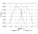
- FIG. 2 is a graph showing the relationship between the position of the magnet and the output of the magnetic sensor in the embodiment of the present invention.
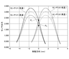
- FIG. 3 is a graph showing a change in the output of the magnetic sensor according to the temperature in the embodiment of the present invention.
- FIG. 4 is a graph showing the relationship between the shape of the magnet and the maximum magnetic flux in the embodiment of the present invention.
- FIG. 5 is a graph showing the relationship between the thickness of the magnet and the magnetic flux density in the embodiment of the present invention.
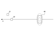
- FIG. 6 is a diagram showing the positional relationship between the track deviation of the magnetic sensor and the magnet in the embodiment of the present invention.
- FIG. 7 is a graph showing the relationship between the deviation of the magnetic sensor in the track direction and the output distribution in the embodiment of the present invention.
- FIG. 8 is a graph showing the relationship between the position of the magnet and the output change rate of the magnetic sensor in the embodiment of the present invention.
- FIG. 9 is a graph showing the relationship between the distance (gap) between the magnetic sensor and the magnet and the magnetic flux density in the embodiment of the present invention.
- FIG. 10 is a graph showing the relationship between the output and the distance in the X direction about the detection point in the embodiment of the present invention.
- FIG. 11 is a graph showing the relationship between the distance in the X direction about the detection point in the embodiment of the present invention and the measured value of the output change rate.
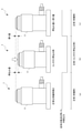
- FIG. 12 is a diagram showing a change in the value of the internal sensor as internal data when the position detection device 1 is normal.
- FIG. 13 is a diagram showing a change in the value of the internal sensor as internal data when the position detection device 1 is abnormal due to a return defect.
- FIG. 14 is a diagram showing a change in the value of the internal sensor as internal data when the position detection device 1 is abnormal due to deterioration of the bearing.
- FIGS. 1 to 14 the same or corresponding components are designated by the same reference numerals, and duplicate description will be omitted. Further, in FIGS. 2 to 14, the scale and dimensions of each component may be exaggerated or some components may be omitted.
- FIG. 1 is a schematic diagram showing the configuration of the position detection device 1 according to the first embodiment of the present invention.
- the position detection device 1 in the present embodiment has a fixed portion 10, a pair of magnetic sensors 21 and 22 fixed on the fixed portion 10, and a magnetic sensor 21 via a signal line 12. It includes a detection unit 30 connected to 22 and a magnet 40 attached to a movable body 2 moved by a detection target such as a tool of a machining center.
- the movable body 2 can move along the X direction (first direction) as shown by an arrow, and the magnet 40 attached to the movable body 2 is on a movement path M extending along the X direction. Is configured to move.
- the position detection device 1 detects whether or not the movable body 2 (and by extension, the detection target such as a tool of the machining center) that can move in the X direction is at a predetermined position (reference line S in FIG. 1). be.
- the magnet 40 has different magnetic poles in the Z direction (second direction).
- the magnetic pole 41 on the + Z direction side of the magnet 40 may be the N pole
- the magnetic pole 42 on the ⁇ Z direction side may be the S pole, or vice versa.
- a rectangular parallelepiped shape, a cube shape, a cylindrical shape, a disk shape, or the like can be considered.
- the magnetic sensors 21 and 22 detect the ambient magnetic field and have the same sensor characteristics (electrical characteristics, magnetic characteristics, temperature characteristics). These magnetic sensors 21 and 22 are arranged on the fixed portion 10 extending in the X direction, and are arranged at positions separated from the moving path M in which the magnet 40 moves by an equal distance in the Z direction.
- the magnetic sensors 21 and 22 have sensor sensing surfaces 21A and 22A perpendicular to the Z direction, respectively. Further, the magnetic sensors 21 and 22 are arranged at the same distance from the reference line S extending in the Z direction. In other words, the reference line S is located on the midpoint of the line segment connecting the two magnetic sensors 21 and 22. As shown in FIG. 1, the distance between the two magnetic sensors 21 and 22 is substantially the same as the length L of the magnet 40 in the X direction.
- the distance between the two magnetic sensors 21 and 22 is substantially the same as the length of the X-direction side of the magnet 40.
- the distance between the magnetic sensors 21 and 22 is substantially the same as the length of the diameter of the circle of the magnet 40.
- Hall elements, magnetic modulation type sensors, magnetic resistance elements, SQUID magnetic sensors and the like can be used.
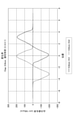
- FIG. 2 is a graph showing the relationship between the position of the magnet 40 and the output of the magnetic sensors 21 and 22.
- the output of the magnetic sensor 21 is shown by a solid line
- the output of the magnetic sensor 22 is shown by a dotted line.
- the horizontal axis of FIG. 2 represents the distance from the reference line S to the center of the magnet 40
- the vertical axis represents the output of the magnetic sensors 21 and 22.
- the distance between the center of the magnetic sensor 21 in the X direction and the center of the magnetic sensor 22 in the X direction is about 3 mm
- the width of the magnet 40 in the X direction is about 4 mm.
- the sensor output of the magnetic sensors 21 and 22 becomes convex according to the position of the magnet 40 in the X direction.
- the magnetic sensor 21 and the magnetic sensor 22 have the same sensor characteristics, when the magnet 40 is located at the midpoint of the line connecting the magnetic sensor 21 and the magnetic sensor 22, that is, it moves.
- the point P where the output characteristic of the magnetic sensor 21 and the output characteristic of the magnetic sensor 22 intersect is located on the reference line S. Therefore, when the output of the magnetic sensor 21 and the output of the magnetic sensor 22 match, it can be determined that the magnet 40 is located on the reference line S.
- the detection unit 30 uses this principle, compares the output from the magnetic sensor 21 with the output from the magnetic sensor 22, and when the two match, the magnet 40 is located on the reference line S. to decide.
- the magnet 40 is on the reference line S. Since the outputs of the magnetic sensors 21 and 22 are likely to change when they are in the vicinity, the points where the outputs of the magnetic sensors 21 and 22 match are more accurately identified. Therefore, the detection accuracy of the position of the magnet 40 is improved.
- the output characteristics of the magnetic sensors 21 and 22 change depending on the temperature, but since the sensor characteristics of the magnetic sensors 21 and 22 are the same, even if the output characteristics of the magnetic sensors 21 and 22 change depending on the temperature, the magnetic sensor 21 The change in the output characteristic of the magnetic sensor 22 and the change in the output characteristic of the magnetic sensor 22 cancel each other out. Therefore, as shown in FIG. 3, the point PL where the output characteristics of the magnetic sensor 21 when the temperature drops and the output characteristics of the magnetic sensor 22 when the temperature drops intersect is located on the reference line S. The point PH at which the output characteristic of the magnetic sensor 21 when the temperature rises and the output characteristic of the magnetic sensor 22 when the temperature rises intersect is also located on the reference line S.
- the magnet 40 is positioned on the reference line S even when the temperature changes. It is possible to stably detect that the magnetism is occurring.
- FIG. 3 the output characteristics of the magnetic sensors 21 and 22 shown in FIG. 2 are shown by thin dotted lines.
- the position of the magnet 40 can be detected stably.
- an external magnetic field in the Z direction or the Y direction perpendicular to the paper surface also acts on both the magnetic sensor 21 and the magnetic sensor 22 in the same manner, and the change in the output characteristic of the magnetic sensor 21 and the change in the output characteristic of the magnetic sensor 22 are mutual. Since they are offset, the position of the magnet 40 can be detected by suppressing the influence of these external magnetic fields.
- the position of the magnet 40 is detected by suppressing the influence of the displacement of the magnet 40 in the Z direction and the Y direction. can do.
- the outputs of the magnetic sensors 21 and 22 may be AD-converted and noise may be reduced by a digital filter.
- the analog outputs of the magnetic sensors 21 and 22 may be applied to a low-pass filter to remove noise.
- the magnet 40 and the sensor substrate are required to be as small as possible for incorporation into precision equipment. Therefore, it is preferable that the magnet 40 is within 5 mm square or ⁇ 5 mm or less. On the other hand, considering the ease of assembling the position detection device 1, it is desired that the magnet 40 has an appropriate size. Therefore, the magnet 40 is preferably 1.5 mm square or larger.
- FIG. 4 shows the relationship between the shape of the magnet and the maximum magnetic flux when the gap between the magnetic sensor 21 and the magnetic sensor 22 and the magnet 40 is 0.8 mm and the thickness (length in the Z direction) of the magnet 40 is 1.0 mm. It is a graph which shows. Each line in FIG. 4 indicates the length of the magnet 40 in the Y direction. That is, FIG.
- the length of the magnet 40 in the Y direction is changed in the X direction of the magnet 40 when the length in the Y direction is 1 mm, 2 mm, 3 mm, 4 mm, and 5 mm, respectively. Shows the change in.
- the length of the magnet 40 in the X direction is less than 1.5 mm, the value of the magnetic flux density is too small, while when it exceeds 3 mm, the value of the magnetic flux density does not change much. .. That is, the length of the magnet 40 in the X direction is preferably 1.5 to 3 mm.
- the length of the magnet 40 in the Y direction is preferably 2 mm to 4 mm.
- FIG. 5 is a graph showing the relationship between the length (thickness) of the magnet 40 in the Z direction and the magnetic flux density when the lengths of the magnet 40 in the X and Y directions are 2 mm ⁇ 3 mm and 3 mm ⁇ 4 mm. be. As shown in the graph of FIG.
- the thickness of the magnet 40 is preferably 1 mm to 3 mm.
- the positioning accuracy in the X direction does not depend on the track deviation of the magnetic sensor 21 and the magnetic sensor 22, but the magnetic sensor.
- the mounting error of the 21 and the magnetic sensor 22 occurs, a position error occurs due to the influence of the track deviation.
- the magnet 40 has a rectangular shape so that the longitudinal direction is the Y direction.
- FIG. 6 is a diagram showing the positional relationship between the track deviation of the magnetic sensor 21 and the magnetic sensor 22 and the case where the magnet 40 is rectangular.
- FIG. 7 shows the track direction when the gap between the magnetic sensor 21 and the magnetic sensor 22 and the magnet 40 is 0.8 mm, and the lengths of the magnet 40 in the X, Y, and Z directions are 3 mm ⁇ 4 mm ⁇ 1 mm.
- It is a graph which shows the relationship between the deviation of a magnetic sensor 21 and a magnetic sensor 22 and an output distribution.
- the magnet 40 has a rectangular shape with the longitudinal direction as the Y direction.
- the output attenuation factor is within the range of 2% even if the deviation in the track direction is 0.3 mm. From this, it can be seen that it is preferable that the magnet 40 has a rectangular shape such that the longitudinal direction is the Y direction.
- the magnet 40 is preferably made of a material that is strong, does not easily rust, and has a good temperature coefficient. More specifically, a samarium-cobalt magnet having a temperature coefficient of ⁇ 0.03% / ° C. and a neodymium magnet having a rust-preventive treatment of ⁇ 0.13% / ° C. are suitable.
- Magnetic sensor spacing When a pair of magnetic sensor 21 and magnetic sensor 22 are surface-mounted, it is preferable that the magnetic sensor 21 and the magnetic sensor 22 are separated by about 1.5 mm or more.
- the length in the X direction of the magnet 40 from which the maximum rate of change of the outputs of the pair of magnetic sensors 21 and the magnetic sensor 22 can be obtained is substantially equal to the mounting distance between the magnetic sensor 21 and the magnetic sensor 22, as described above, When the magnetic sensor 21 and the magnetic sensor 22 are separated by about 1.5 mm or more, it is preferable that the length of the magnet 40 in the X direction is also about 1.5 mm or more.
- the gap between the pair of magnetic sensors 21 and the magnetic sensor 22 and the magnet 40 is 0.8 mm, and the lengths of the magnets in the X, Y, and Z directions are 3 mm ⁇ 4 mm ⁇ 1 mm.
- the relationship between the position of the magnet 40 and the output change rate of the magnetic sensor 21 and the magnetic sensor 22 when the length of the magnet 40 in the X direction is substantially equal to the mounting distance between the magnetic sensor 21 and the magnetic sensor 22. It is a graph which shows. As shown in FIG. 8, when the position of the magnet 40 is 0, that is, when the magnet 40 is located on the reference line, both the absolute values of the output change rates of the magnetic sensor 21 and the magnetic sensor 22 are substantially maximum.
- the distance (gap) between the pair of magnetic sensors 21 and the magnetic sensor 22 and the magnet 40 is determined by repeatability, component accuracy, assembly accuracy, ease of assembly confirmation, and the like. Specifically, for example, considering that a component accuracy of ⁇ 0.1 mm, a mounting accuracy of 0.2 mm, and a mechanical variation, that is, a variation of 0.1 mm or less due to, for example, shaft play, is required. It is determined. As a result, the distance (gap) between the pair of magnetic sensors 21 and the magnet 40 is preferably 0.3 mm or more and 0.8 mm or less.
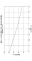
- FIG. 9 is a graph showing the relationship between the distance (gap) between the pair of magnetic sensors 21 and the magnetic sensor 22 and the magnet 40, and the magnetic flux density.
- the distance (gap) is 0.3 mm or more and 0.8 mm or less
- the magnetic flux density is generally 120 mT or more and 170 mT or less.
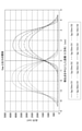
- FIG. 10 is centered on the detection point when the distances (gap) between the pair of magnetic sensors 21 and the magnetic sensors 22 and the magnet 40 are 0.4 mm, 0.6 mm, 0.8 mm, and 1.0 mm. It is a graph which shows the relationship between the distance in the X direction, and an output. In the graph of FIG. 10, "Ch1" indicates the output of the magnetic sensor 21, and “Ch2" indicates the output of the magnetic sensor 22. As can be seen from FIG. 10, the graph in which the distance (gap) between the pair of magnetic sensors 21 and the magnetic sensor 22 and the magnet 40 is 1.0 mm is shown to have a smaller output than the other graphs. ..
- FIG. 11 is centered on a detection point when the distance (gap) between the pair of magnetic sensors 21 and the magnetic sensor 22 and the magnet 40 is 0.4 mm, 0.6 mm, 0.8 mm, and 1.0 mm. It is a graph which shows the relationship between the distance in the X direction and the measured value of the output change rate.
- "Ch1" indicates the output change rate of the magnetic sensor 21
- "Ch2" indicates the output change rate of the magnetic sensor 22.
- the graph in which the distance (gap) between the pair of magnetic sensors 21 and the magnetic sensor 22 and the magnet 40 is 1.0 mm has a smaller absolute value of the output change rate than the other graphs. Was shown.
- FIGS. 12 to 14 a method for detecting return failure and bearing deterioration using internal data will be described.
- FIG. 12 is an internal output using a conventional contact, and shows an internal output in a situation where the contact 11 is pushed in and then returned.
- the contact 11 is at a normal standby height during standby. Subsequently, the contact 11 is pushed in as shown in (b). After that, when the load on the contact 11 is removed, the contact 11 returns to the original position as shown in (c). At this time, since the standby height of the contact 11 in (a) is equal to the standby height of the contact 11 in (c), the pushing amount of the contact 11 from (a) to (b) is used. , (B) to (c) is equal to the return amount of the contact 11. Further, the value of the internal sensor is also equal to the value before the contact 11 is pushed in and the value after the contact 11 is pushed in and then returned.
- FIG. 13 shows a change in the value of the internal sensor as internal data when the position detection device 1 is abnormal due to a return defect.
- cutting fluid and chips are attached to the region where the contact 11 of the position detection device 1 slides. Therefore, when going from (b) to (c), the contact 11 does not return to the normal position. Therefore, the return amount of the contact 11 when going from (b) to (c) is smaller than the pushing amount of the contact 11 when going from (a) to (b).
- the value after pushing the contact 11 and returning is smaller than the value before pushing the contact 11.
- FIG. 14 shows the value of the internal sensor as internal data when the position detection device 1 is abnormal due to deterioration of the bearing.
- the value of the internal sensor does not fluctuate during normal standby.
- the contact 11 also vibrates in accordance with the machining vibration, the vibration when attaching / detaching the workpiece, the vibration when the sensor is stowed or carried out, and the impact due to the pallet change.
- the value of the internal sensor fluctuates.
- the outputs of the magnetic sensor 21 and the magnetic sensor 22 during standby of the position detection device 1 and the magnet 40 are moved in the X direction, and then the magnet 40 returns in the direction opposite to the X direction.
- a comparison means (not shown) for comparing the outputs of the magnetic sensor 21 and the magnetic sensor 22 at the time of completion, and a first diagnostic means (not shown) for diagnosing an abnormality in the position detection device 1 based on the comparison result by the comparison unit. (Fig.) And may be further provided.
- the position detection device 1 provides a second diagnostic means (not shown) for diagnosing an abnormality of the position detection device 1 based on the waveforms of the outputs of the magnetic sensor 21 and the magnetic sensor 22 during standby of the position detection device 1. Further may be provided.
- a position detection device having a long life, high detection accuracy, and stable position detection.
- the position detection device comprises a magnet configured to move with the movable body on a movement path extending along a first direction. This magnet has different magnetic poles in the second direction perpendicular to the first direction.
- the position detection device includes a pair of magnetic sensors arranged at the same distance from the reference line extending in the second direction while being separated from the movement path by the same distance in the second direction.
- the pair of magnetic sensors has the same sensor characteristics.
- the position detection device is a detection unit configured to detect that the magnet is located on the reference line when the absolute value of the output change rate of both of the pair of magnetic sensors becomes substantially maximum. To prepare for.
- the position detection device makes it possible to detect that the magnet is located on the reference line without using mechanical contacts. That is, according to the position detection device according to the present invention, it is possible to detect the position of the movable body without using mechanical contacts. As described above, since the position detection device according to the present invention does not use mechanical contacts, there are problems such as shortening of life due to deterioration of contacts, poor continuity between contacts, and deterioration of detection accuracy due to wear and dents of contacts. Does not occur. Further, since the change in the output characteristics of the magnetic sensor due to the temperature change or the like cancels each other out between the pair of magnetic sensors, the position of the magnet can be stably detected.
- the output of the pair of magnetic sensors exhibits the maximum rate of change when the magnet is located on the reference line.
- the output of the magnetic sensor is likely to change when the magnet is near the reference line, so that the point where the outputs of the magnetic sensor match can be identified more accurately, and the detection accuracy of the position of the magnet can be improved. It gets higher.
- a position detection device having a long life, high detection accuracy, and stable position detection.
- a position detection device capable of failure diagnosis and maintenance prediction is provided.
- the present invention is suitably used for a position detection device that detects the position of a movable body.
Landscapes
- Physics & Mathematics (AREA)
- General Physics & Mathematics (AREA)
- Measurement Of Length, Angles, Or The Like Using Electric Or Magnetic Means (AREA)
- Transmission And Conversion Of Sensor Element Output (AREA)
Abstract
長寿命で、検出精度が高く、安定して位置検出を行うことができる位置検出装置を提供する。 位置検出装置1は、X方向に沿って延びる移動経路M上を可動体2とともに移動するように構成される磁石40を備える。磁石40は、Z方向において異なる磁極41,42を有する。位置検出装置1は、移動経路MからZ方向に等しい距離だけ離間するとともに、Z方向に延びる基準線Sから等しい距離に配置された1対の磁気センサ21,22を備える。磁気センサ21,22は、同一のセンサ特性を有する。位置検出装置2は、磁気センサ21,22の双方の出力変化率が略最大となった状態で磁石40が基準線S上に位置したことを検出するように構成される検出部30を備える。
Description
本発明は、位置検出装置に係り、特に可動体の位置を検出する位置検出装置に関するものである。
例えば、マシニングセンタのような工作機械においては、正確な加工を実現するために工具の初期位置を検出する必要がある。このような工具などの検出対象により移動させられる可動体の位置を検出する位置検出装置として、可動体の移動に応じて電気的接点を機械的にオン/オフするようにしたものが知られている(例えば、特許文献1参照)。
しかしながら、このような従来の位置検出装置では、機械的にオン/オフすることを繰り返すことにより接点が劣化するため、寿命が短いという問題がある。また、異物の混入や酸化皮膜の形成により接点間の導通不良が生じたり、繰り返し接触することによる接点の摩耗や凹みなどにより検出精度が低下したりする問題もある。
本発明は、このような従来技術の問題点に鑑みてなされたもので、長寿命で、検出精度が高く、安定して位置検出を行うことができる位置検出装置を提供することを目的とする。
本発明の一態様によれば、長寿命で、検出精度が高く、安定して位置検出を行うことができる位置検出装置が提供される。この位置検出装置は、第1の方向に沿って延びる移動経路上を可動体とともに移動するように構成される磁石を備える。この磁石は、上記第1の方向に垂直な第2の方向において異なる磁極を有する。また、上記位置検出装置は、上記移動経路から上記第2の方向に等しい距離だけ離間するとともに、上記第2の方向に延びる基準線から等しい距離に配置された1対の磁気センサを備える。上記1対の磁気センサは、同一のセンサ特性を有する。上記位置検出装置は、上記1対の磁気センサの双方の出力変化率の絶対値が略最大となった状態で上記磁石が上記基準線上に位置したことを検出するように構成される検出部を備える。
以下、本発明に係る位置検出装置の実施形態について図1から図14を参照して詳細に説明する。なお、図1から図14において、同一又は相当する構成要素には、同一の符号を付して重複した説明を省略する。また、図2から図14においては、各構成要素の縮尺や寸法が誇張されて示されている場合や一部の構成要素が省略されている場合がある。
〔1 基本構成〕
図1は、本発明の第1の実施形態における位置検出装置1の構成を示す模式図である。図1に示すように、本実施形態における位置検出装置1は、固定部10と、固定部10上に固定された1対の磁気センサ21,22と、信号線12を介して磁気センサ21,22に接続された検出部30と、例えばマシニングセンタの工具などの検出対象により移動させられる可動体2に取り付けられた磁石40とを含んでいる。可動体2は、矢印で示すようにX方向(第1の方向)に沿って移動可能となっており、この可動体2に取り付けられた磁石40は、X方向に沿って延びる移動経路M上を移動するように構成されている。位置検出装置1は、このようにX方向に移動可能な可動体2(ひいてはマシニングセンタの工具などの検出対象)が所定の位置(図1の基準線S)にあるか否かを検出するものである。
図1は、本発明の第1の実施形態における位置検出装置1の構成を示す模式図である。図1に示すように、本実施形態における位置検出装置1は、固定部10と、固定部10上に固定された1対の磁気センサ21,22と、信号線12を介して磁気センサ21,22に接続された検出部30と、例えばマシニングセンタの工具などの検出対象により移動させられる可動体2に取り付けられた磁石40とを含んでいる。可動体2は、矢印で示すようにX方向(第1の方向)に沿って移動可能となっており、この可動体2に取り付けられた磁石40は、X方向に沿って延びる移動経路M上を移動するように構成されている。位置検出装置1は、このようにX方向に移動可能な可動体2(ひいてはマシニングセンタの工具などの検出対象)が所定の位置(図1の基準線S)にあるか否かを検出するものである。
磁石40は、Z方向(第2の方向)において異なる磁極を有している。例えば、図1に示すように磁石40の+Z方向側の磁極41がN極、-Z方向側の磁極42がS極であってもよいし、あるいはこの逆であってもよい。磁石40の形状としては、直方体状、立方体状、円筒状、円板状のものなどが考えられる。
磁気センサ21,22は、周囲の磁場を検出するものであり、同一のセンサ特性(電気特性・磁気特性・温度特性)を有している。これらの磁気センサ21,22は、X方向に延びる固定部10上に並べられており、磁石40が移動する移動経路MからZ方向に等しい距離だけ離間した位置に配置されている。磁気センサ21,22は、それぞれZ方向に垂直なセンサ感知面21A,22Aを有している。また、磁気センサ21,22は、Z方向に延びる基準線Sから等しい距離に配置されている。換言すれば、2つの磁気センサ21,22を結ぶ線分の中点上に基準線Sが位置している。なお、図1に示すように、2つの磁気センサ21及び22の間の距離は、磁石40のX方向の長さLと略同一である。とりわけ、磁石40の形状が直方体状、及び立方体状の場合には、2つの磁気センサ21及び22の間の距離は、磁石40のX方向の辺の長さと略同一である。また、磁石40の形状が円筒状、又は円板状の場合には、磁気センサ21及び22の間の距離は、磁石40の円の直径の長さと略同一である。このような磁気センサ21,22としては、ホール素子、磁気変調型センサ、磁気抵抗素子、SQUID磁気センサなどを用いることができる。
検出部30には、磁気センサ21,22からの出力が入力されており、検出部30は、これらの磁気センサ21,22からの出力を比較する比較回路を含んでいる。図2は、磁石40の位置と磁気センサ21,22の出力との関係を示すグラフである。図2において、磁気センサ21の出力は実線で、磁気センサ22の出力は点線で示されている。図2の横軸は基準線Sから磁石40の中心までの距離を表しており、縦軸は磁気センサ21,22の出力を表している。なお、この例では、磁気センサ21のX方向の中心と磁気センサ22のX方向の中心との間の距離を約3mmとし、磁石40のX方向の幅を約4mmとしている。
図2に示すように、磁石40のX方向の位置に応じて磁気センサ21,22のセンサ出力は凸状となる。ここで、磁気センサ21と磁気センサ22とは同一のセンサ特性を有しているため、磁石40が磁気センサ21と磁気センサ22とを結ぶ線分の中点に位置しているとき、すなわち移動距離=0mmのとき(磁石40が基準線S上に位置しているとき)、両者のセンサ出力が一致する。換言すれば、図2に示すように、磁気センサ21の出力特性と磁気センサ22の出力特性とが交差する点Pは基準線S上に位置することとなる。したがって、磁気センサ21の出力と磁気センサ22の出力とが一致しているときには、磁石40が基準線S上に位置していると判断することができる。検出部30は、この原理を用いるものであり、磁気センサ21からの出力と磁気センサ22からの出力とを比較し、両者が一致したときに磁石40が基準線S上に位置していると判断する。
このような構成により、機械的な接点を用いることなく、磁石40が基準線S上に位置したことを検出することができる。すなわち、本実施形態の位置検出装置1によれば、機械的な接点を用いることなく、可動体2の位置を検出することが可能となる。このように機械的な接点を用いないため、接点の劣化による寿命の短縮化や接点間の導通不良、接点の摩耗や凹みによる検出精度の低下といった問題が生じない。
ここで、磁石40が基準線S上に位置しているときに磁気センサ21,22の出力の変化率が最大となるように磁気センサ21,22を配置すれば、磁石40が基準線Sの近傍にあるときに磁気センサ21,22の出力が変化しやすくなるため、磁気センサ21,22の出力が一致する点がより正確に特定される。したがって、磁石40の位置の検出精度が高くなる。
また、磁気センサ21,22の出力特性は温度によって変化するが、磁気センサ21,22のセンサ特性が同一であるため、磁気センサ21,22の出力特性が温度によって変化しても、磁気センサ21の出力特性の変化と磁気センサ22の出力特性の変化とが互いに相殺される。このため、図3に示すように、温度が低下した際の磁気センサ21の出力特性と温度が低下した際の磁気センサ22の出力特性とが交差する点PLは基準線S上に位置し、温度が上昇した際の磁気センサ21の出力特性と温度が上昇した際の磁気センサ22の出力特性とが交差する点PHも基準線S上に位置する。したがって、上述したように、磁気センサ21の出力と磁気センサ22の出力とが一致しているか否かを判断することで、温度が変化した場合においても、磁石40が基準線S上に位置していることを安定して検出することができる。なお、図3においては、図2に示す磁気センサ21,22の出力特性は細い点線で示されている。
同様に、磁気センサ21,22の電気的特性や磁気特性が変化した場合においても、磁気センサ21の出力特性の変化と磁気センサ22の出力特性の変化とが互いに相殺されるため、磁石40の位置を安定して検出することができる。また、Z方向や紙面に垂直なY方向における外部磁場も磁気センサ21と磁気センサ22の両方に同様に作用し、磁気センサ21の出力特性の変化と磁気センサ22の出力特性の変化とが互いに相殺されるため、これらの外部磁場の影響を抑えて磁石40の位置を検出することができる。また、磁石40のZ方向やY方向の変位に対する磁気センサ21,22の出力特性の変化が相殺されるため、磁石40のZ方向やY方向の変位の影響を抑えて磁石40の位置を検出することができる。
なお、磁気センサ21,22の出力をAD変換してデジタルフィルタによってノイズを低減してもよい。あるいは、磁気センサ21,22のアナログ出力をローパスフィルターにかけてノイズを除去してもよい。
〔2 構成の具体例〕
〔2.1 磁石の大きさ〕
磁石40及びセンサ基板は、精密機器に組み込むために出来るだけ小さいことが要求される。そこで、磁石40は、5mm角以内、又はφ5mm以下とすることが好適である。一方で、位置検出装置1の組み立て作業のしやすさを考慮すると、磁石40は適度な大きさを有することが望まれるため、磁石40は、1.5mm角以上とすることが好適である。
〔2.1 磁石の大きさ〕
磁石40及びセンサ基板は、精密機器に組み込むために出来るだけ小さいことが要求される。そこで、磁石40は、5mm角以内、又はφ5mm以下とすることが好適である。一方で、位置検出装置1の組み立て作業のしやすさを考慮すると、磁石40は適度な大きさを有することが望まれるため、磁石40は、1.5mm角以上とすることが好適である。
〔2.2 磁石の形状〕
磁石40は磁場が強いほど、S/N比の値が良くなると共に、繰り返し精度が良くなる。すなわち、磁石40は、大きく厚いことが望まれる。また、磁気センサ21及び磁気センサ22と磁石40との距離がより近いことが望まれる。
図4は、磁気センサ21及び磁気センサ22と磁石40とのギャップを0.8mm、磁石40の厚み(Z方向の長さ)を1.0mmとした際の磁石の形状と最大磁束の関係を示すグラフである。図4中の各々の線は、磁石40のY方向の長さを示す。すなわち、図4は、磁石40のY方向の長さが、1mm、2mm、3mm、4mm、及び5mmの各々の場合において、磁石40のX方向の長さを変化させた場合の磁束密度の値の変化を示している。図4のグラフから分かるように、磁石40のX方向の長さは、1.5mmを下回ると磁束密度の値が小さすぎる一方で、3mmを超えても、磁束密度の値にあまり変化はない。すなわち、磁石40のX方向の長さは、1.5~3mmとすることが好適である。一方で、磁石40のY方向の長さは、2mm~4mmとすることが好適である。
磁石40は磁場が強いほど、S/N比の値が良くなると共に、繰り返し精度が良くなる。すなわち、磁石40は、大きく厚いことが望まれる。また、磁気センサ21及び磁気センサ22と磁石40との距離がより近いことが望まれる。
図4は、磁気センサ21及び磁気センサ22と磁石40とのギャップを0.8mm、磁石40の厚み(Z方向の長さ)を1.0mmとした際の磁石の形状と最大磁束の関係を示すグラフである。図4中の各々の線は、磁石40のY方向の長さを示す。すなわち、図4は、磁石40のY方向の長さが、1mm、2mm、3mm、4mm、及び5mmの各々の場合において、磁石40のX方向の長さを変化させた場合の磁束密度の値の変化を示している。図4のグラフから分かるように、磁石40のX方向の長さは、1.5mmを下回ると磁束密度の値が小さすぎる一方で、3mmを超えても、磁束密度の値にあまり変化はない。すなわち、磁石40のX方向の長さは、1.5~3mmとすることが好適である。一方で、磁石40のY方向の長さは、2mm~4mmとすることが好適である。
また、磁石40の磁化方向の磁場は、磁石40の厚み(Z方向の長さ)にほぼ比例するが、厚すぎると磁石40の形状が大きくなり、切り粉の付着を防ぐためにも、磁気シールドを強力にする必要があるため、磁石40の厚みを適度な範囲とすることが望ましい。
図5は、磁石40のX方向及びY方向の長さを、2mm×3mm及び3mm×4mmとした場合の、磁石40のZ方向の長さ(厚み)と磁束密度との関係を示すグラフである。図5のグラフに示されるように、磁石40の厚みが1mmを下回ると磁束密度が小さすぎる一方で、厚みが3mmを超えると、磁束密度の値にあまり変化がない。すなわち、磁石40の厚みは、1mm~3mmとすることが好適である。
図5は、磁石40のX方向及びY方向の長さを、2mm×3mm及び3mm×4mmとした場合の、磁石40のZ方向の長さ(厚み)と磁束密度との関係を示すグラフである。図5のグラフに示されるように、磁石40の厚みが1mmを下回ると磁束密度が小さすぎる一方で、厚みが3mmを超えると、磁束密度の値にあまり変化がない。すなわち、磁石40の厚みは、1mm~3mmとすることが好適である。
また、本実施形態で用いる磁気センサ21及び磁気センサ22を含む位置検出装置1の原理に基づけば、X方向の位置決め精度は、磁気センサ21及び磁気センサ22のトラックずれに依存しないが、磁気センサ21及び磁気センサ22の実装誤差が生じた場合には、トラックずれの影響により、位置誤差が発生する。このとき、磁石40として、小型でかつ丸型や正方形の磁石を使用すると、トラックすなわちX軸から、Y方向の外側に向かって、磁場の減衰が大きくなり、S/N比が落ちやすく、原点位置ずれが発生しやすい。このため、磁石40は、長手方向がY方向となるような長方形とすることが望ましい。
図6は、磁気センサ21及び磁気センサ22のトラックずれと、磁石40が長方形だった場合の位置関係を示す図である。図6に示すように、磁石40の磁場は、長手方向をY方向とするような楕円状となっているため、トラックずれの影響は小さくなる。
図7は、磁気センサ21及び磁気センサ22と磁石40とのギャップが0.8mm、磁石40のX方向、Y方向、Z方向の長さが3mm×4mm×1mmだった場合の、トラック方向の磁気センサ21及び磁気センサ22のずれと、出力分布との関係を示すグラフである。磁石40は長手方向をY方向とする長方形の形状であるが、この場合、トラック方向のずれが0.3mmあったとしても、出力の減衰率は2%の範囲に収まる。このことからも、磁石40は、長手方向がY方向となるような長方形とすることが好適であることが分かる。
図6は、磁気センサ21及び磁気センサ22のトラックずれと、磁石40が長方形だった場合の位置関係を示す図である。図6に示すように、磁石40の磁場は、長手方向をY方向とするような楕円状となっているため、トラックずれの影響は小さくなる。
図7は、磁気センサ21及び磁気センサ22と磁石40とのギャップが0.8mm、磁石40のX方向、Y方向、Z方向の長さが3mm×4mm×1mmだった場合の、トラック方向の磁気センサ21及び磁気センサ22のずれと、出力分布との関係を示すグラフである。磁石40は長手方向をY方向とする長方形の形状であるが、この場合、トラック方向のずれが0.3mmあったとしても、出力の減衰率は2%の範囲に収まる。このことからも、磁石40は、長手方向がY方向となるような長方形とすることが好適であることが分かる。
〔2.3 磁石の材質〕
磁石40は、強く、錆びにくく、温度係数が良い材質が望ましい。より具体的には、温度係数が-0.03%/℃のサマリュウムコバルト磁石や、-0.13%/℃の防錆処理をしたネオジム磁石が好適である。
磁石40は、強く、錆びにくく、温度係数が良い材質が望ましい。より具体的には、温度係数が-0.03%/℃のサマリュウムコバルト磁石や、-0.13%/℃の防錆処理をしたネオジム磁石が好適である。
〔2.4 磁気センサの間隔〕
1対の磁気センサ21及び磁気センサ22を表面実装する場合、磁気センサ21と磁気センサ22とを、略1.5mm以上離すことが好適である。
1対の磁気センサ21及び磁気センサ22を表面実装する場合、磁気センサ21と磁気センサ22とを、略1.5mm以上離すことが好適である。
〔2.5 磁石と磁気センサとの関係〕
1対の磁気センサ21及び磁気センサ22の出力の最大変化率を得られる磁石40のX方向の長さは、磁気センサ21と磁気センサ22との実装距離に略等しいので、上記のように、磁気センサ21と磁気センサ22とが略1.5mm以上離れている場合、磁石40のX方向の長さも略1.5mm以上の長さとすることが好適である。
図8は、1対の磁気センサ21及び磁気センサ22と磁石40とのギャップが0.8mmであり、磁石のX方向、Y方向、及びZ方向の長さが、3mm×4mm×1mmであると共に、磁石40のX方向の長さが、磁気センサ21と磁気センサ22との実装距離に略等しい場合における、磁石40の位置と、磁気センサ21及び磁気センサ22の出力変化率との関係を示すグラフである。図8に示されるように、磁石40の位置が0、すなわち磁石40が基準線上に位置したとき、磁気センサ21及び磁気センサ22の出力変化率の絶対値の双方が略最大となっている。
1対の磁気センサ21及び磁気センサ22の出力の最大変化率を得られる磁石40のX方向の長さは、磁気センサ21と磁気センサ22との実装距離に略等しいので、上記のように、磁気センサ21と磁気センサ22とが略1.5mm以上離れている場合、磁石40のX方向の長さも略1.5mm以上の長さとすることが好適である。
図8は、1対の磁気センサ21及び磁気センサ22と磁石40とのギャップが0.8mmであり、磁石のX方向、Y方向、及びZ方向の長さが、3mm×4mm×1mmであると共に、磁石40のX方向の長さが、磁気センサ21と磁気センサ22との実装距離に略等しい場合における、磁石40の位置と、磁気センサ21及び磁気センサ22の出力変化率との関係を示すグラフである。図8に示されるように、磁石40の位置が0、すなわち磁石40が基準線上に位置したとき、磁気センサ21及び磁気センサ22の出力変化率の絶対値の双方が略最大となっている。
また、1対の磁気センサ21及び磁気センサ22と磁石40との距離(ギャップ)は、繰返し精度、部品精度、組立て精度、組立て確認しやすさ等で決定される。具体的には、例えば部品精度として±0.1mm、実装精度として0.2mm、メカ変動、すなわち、例えば軸のガタ等に由来する変動として0.1mm以下の値が求められることを考慮して決定される。その結果、1対の磁気センサ21と磁石40との距離(ギャップ)は、0.3mm以上0.8mm以下とすることが好適である。
図9は、1対の磁気センサ21及び磁気センサ22と磁石40との距離(ギャップ)と、磁束密度との関係を示すグラフである。当該距離(ギャップ)が0.3mm以上0.8mm以下の場合、磁束密度は、概して、120mT以上170mT以下となる。
図10は、1対の磁気センサ21及び磁気センサ22と磁石40との距離(ギャップ)が、0.4mm、0.6mm、0.8mm、1.0mmの場合の、検出点を中心にしたX方向の距離と、出力との関係を示すグラフである。なお、図10のグラフにおいて、「Ch1」は磁気センサ21の出力を示し、「Ch2」は磁気センサ22の出力を示す。図10から分かるように、1対の磁気センサ21及び磁気センサ22と磁石40との距離(ギャップ)が1.0mmのグラフは、他のグラフに比較して、出力が小さいことが示された。
図11は、1対の磁気センサ21及び磁気センサ22と磁石40との距離(ギャップ)の間隔が、0.4mm、0.6mm、0.8mm、1.0mmの場合の、検出点を中心にしたX方向の距離と、出力変化率の実測値との関係を示すグラフである。なお、図11のグラフにおいて、「Ch1」は磁気センサ21の出力変化率を示し、「Ch2」は磁気センサ22の出力変化率を示す。図10から分かるように、1対の磁気センサ21及び磁気センサ22と磁石40との距離(ギャップ)が1.0mmのグラフは、他のグラフに比較して、出力変化率の絶対値が小さいことが示された。
〔3 内部データの活用例〕
上記の位置検出装置1の内部データである磁力データ(センサデータ)を監視することで、1対の磁気センサ21及び磁気センサ22の状態を把握することにより、位置検出装置1の故障診断をすることが可能である。より詳細には、内部データを監視することにより、位置検出装置1のメンテナンス時期の診断、1対の磁気センサ21及び磁気センサ22の故障の診断、位置検出装置1の使用環境診断が可能となる。
上記の位置検出装置1の内部データである磁力データ(センサデータ)を監視することで、1対の磁気センサ21及び磁気センサ22の状態を把握することにより、位置検出装置1の故障診断をすることが可能である。より詳細には、内部データを監視することにより、位置検出装置1のメンテナンス時期の診断、1対の磁気センサ21及び磁気センサ22の故障の診断、位置検出装置1の使用環境診断が可能となる。
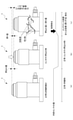
メンテナンス時期の診断のためには、内部データを用いて、位置検出装置1の摺動部に切り粉や切削液が付着、堆積したことによる戻り不良を把握したり、動作回数を把握したりすることが有効である。1対の磁気センサ21及び磁気センサ22の故障の診断のためには、切子や切削液の付着、内部負圧、軸受の劣化に起因する戻り不良を把握したり、衝突による廻止め破損を把握したりすることが有効である。使用環境診断のためには、例えば、周辺温度が変化したことにより、位置検出装置1の内部が負圧になったことに起因する戻り不良を把握したり、加工振動、パレットチェンジによる衝撃、ワーク着脱、クランプ/アンクランプによる衝撃、及び、格納搬出による衝撃に起因する軸受の劣化を把握したりすることが有効である。
以下、図12~図14を参照することにより、内部データを用いた戻り不良、及び軸受の劣化の検知方法について説明する。
図12は、従来の接点を用いた内部出力であって、コンタクト11を押し込んだ後、戻ってくる状況における内部出力を示す。
図12において、(a)に示すように、待機時にはコンタクト11が正常な待機時高さにある。続いて、(b)に示すようにコンタクト11を押し込む。その後、コンタクト11への負荷を外すと、(c)に示すようにコンタクト11は元の位置に戻る。この際、(a)でのコンタクト11の待機時高さと、(c)でのコンタクト11の待機時高さとは等しいことから、(a)から(b)に至る際のコンタクト11の押込み量と、(b)から(c)に至る際のコンタクト11の戻り量とは等しくなる。また、内部センサの値に関しても、コンタクト11の押込み前の値と、コンタクト11を押し込んでから戻った後の値とは等しい。
図13は、戻り不良があるために位置検出装置1が異常である場合の、内部データとしての内部センサの値の変化を示す。
図13に示す例においては、(c)に示すように、位置検出装置1のコンタクト11が摺動する領域に、切削液や切り粉が付着している。このため、(b)から(c)に至る際、コンタクト11は正常な位置まで復帰しない。したがって、(a)から(b)に至る際のコンタクト11の押込み量よりも、(b)から(c)に至る際のコンタクト11の戻り量は小さくなる。また、内部センサの値に関しても、コンタクト11の押込み前の値よりも、コンタクト11を押し込んでから戻った後の値は小さくなる。
図13に示す例においては、(c)に示すように、位置検出装置1のコンタクト11が摺動する領域に、切削液や切り粉が付着している。このため、(b)から(c)に至る際、コンタクト11は正常な位置まで復帰しない。したがって、(a)から(b)に至る際のコンタクト11の押込み量よりも、(b)から(c)に至る際のコンタクト11の戻り量は小さくなる。また、内部センサの値に関しても、コンタクト11の押込み前の値よりも、コンタクト11を押し込んでから戻った後の値は小さくなる。
図14は、軸受けの劣化があるために位置検出装置1が異常である場合の、内部データとしての内部センサの値を示す。(a)に示すように、正常な待機時においては、内部センサの値が変動することはない。一方で、軸受けの劣化がある場合には、加工振動や被加工物着脱時の振動、センサの格納、搬出時の振動、パレットチェンジによる衝撃が発生した場合に、コンタクト11もそれに合わせて振動してしまい、(b)に示すように、内部センサの値は変動してしまう。
このため、位置検出装置1は、位置検出装置1の待機時における磁気センサ21及び磁気センサ22の出力と、磁石40をX方向に移動させた後、磁石40がX方向とは逆方向に戻り終えた時点の磁気センサ21及び磁気センサ22の出力とを比較する比較手段(不図示)と、比較部による当該比較結果に基づいて、位置検出装置1の異常を診断する第1診断手段(不図示)とを更に備えてもよい。
また、位置検出装置1は、位置検出装置1の待機時における、磁気センサ21及び磁気センサ22の出力の波形に基づいて、位置検出装置1の異常を診断する第2診断手段(不図示)を更に備えてもよい。
〔4 実施形態が奏する効果〕
以上述べたように、本発明の一態様によれば、長寿命で、検出精度が高く、安定して位置検出を行うことができる位置検出装置が提供される。この位置検出装置は、第1の方向に沿って延びる移動経路上を可動体とともに移動するように構成される磁石を備える。この磁石は、上記第1の方向に垂直な第2の方向において異なる磁極を有する。また、上記位置検出装置は、上記移動経路から上記第2の方向に等しい距離だけ離間するとともに、上記第2の方向に延びる基準線から等しい距離に配置された1対の磁気センサを備える。上記1対の磁気センサは、同一のセンサ特性を有する。上記位置検出装置は、上記1対の磁気センサの双方の出力変化率の絶対値が略最大となったときに、上記磁石が上記基準線上に位置したことを検出するように構成される検出部を備える。
以上述べたように、本発明の一態様によれば、長寿命で、検出精度が高く、安定して位置検出を行うことができる位置検出装置が提供される。この位置検出装置は、第1の方向に沿って延びる移動経路上を可動体とともに移動するように構成される磁石を備える。この磁石は、上記第1の方向に垂直な第2の方向において異なる磁極を有する。また、上記位置検出装置は、上記移動経路から上記第2の方向に等しい距離だけ離間するとともに、上記第2の方向に延びる基準線から等しい距離に配置された1対の磁気センサを備える。上記1対の磁気センサは、同一のセンサ特性を有する。上記位置検出装置は、上記1対の磁気センサの双方の出力変化率の絶対値が略最大となったときに、上記磁石が上記基準線上に位置したことを検出するように構成される検出部を備える。
これにより、機械的な接点を用いることなく、磁石が基準線上に位置したことを検出することができる。すなわち、本発明に係る位置検出装置によれば、機械的な接点を用いることなく、可動体の位置を検出することが可能となる。このように本発明に係る位置検出装置によれば、機械的な接点を用いないため、接点の劣化による寿命の短縮化や接点間の導通不良、接点の摩耗や凹みによる検出精度の低下といった問題が生じない。また、温度変化などによる磁気センサの出力特性の変化が1対の磁気センサ間で互いに相殺されるため、磁石の位置を安定して検出することができる。
上記1対の磁気センサの出力は、上記磁石が上記基準線上に位置したときに最大の変化率を呈することが好ましい。このようにすることで、磁石が基準線の近傍にあるときに磁気センサの出力が変化しやすくなるため、磁気センサの出力が一致する点がより正確に特定され、磁石の位置の検出精度が高くなる。
本発明によれば、長寿命で、検出精度が高く、安定して位置検出を行うことができる位置検出装置が提供される。
また、本発明によれば、故障診断や、保全予知もできる位置検出装置が提供される。
本発明は、可動体の位置を検出する位置検出装置に好適に用いられる。
1 位置検出装置
2 可動体
10 固定部
21,22 磁気センサ
30 検出部
40 磁石
41,42 磁極
M 移動経路
S 基準線
2 可動体
10 固定部
21,22 磁気センサ
30 検出部
40 磁石
41,42 磁極
M 移動経路
S 基準線
Claims (13)
- 第1の方向に沿って延びる移動経路上を可動体とともに移動するように構成される磁石であって、前記第1の方向に垂直な第2の方向において異なる磁極を有する磁石と、
前記移動経路から前記第2の方向に等しい距離だけ離間するとともに、前記第2の方向に延びる基準線から等しい距離に配置された1対の磁気センサであって、同一のセンサ特性を有する1対の磁気センサと、
前記1対の磁気センサの双方の出力変化率の絶対値が略最大となった状態で前記磁石が前記基準線上に位置したことを検出するように構成される検出部と
を備える位置検出装置。 - 前記1対の磁気センサ間の距離と、前記磁石の前記第1の方向の長さとが略等しい、請求項1に記載の位置検出装置。
- 前記磁石の前記第1の方向の長さは、略1.5mm以上である、請求項1又は請求項2に記載の位置検出装置。
- 前記磁石は略5mm角以内の大きさである、請求項1から請求項3のいずれか1項に記載の位置検出装置。
- 前記磁石は略1.5mm角以上の大きさである、請求項1から請求項4のいずれか1項に記載の位置検出装置。
- 前記磁石は、前記第1の方向の長さが略1.5mm~3mmであり、前記第2の方向の長さが略2mm以上、略4mm以下である、請求項1から請求項5のいずれか1項に記載の位置検出装置。
- 前記磁石は、前記第1の方向及び前記第2の方向に垂直な第3の方向の長さが略1mm以上、略3mm以下である、請求項1から請求項6のいずれか1項に記載の位置検出装置。
- 前記磁石の形状は長方形であり、当該長方形の対称軸が、前記第1の方向及び前記第2の方向に一致する、請求項1から請求項7のいずれか1項に記載の位置検出装置。
- 前記1対の磁気センサは、前記第1の方向に、略1.5mm以上離間する、請求項1から請求項8のいずれか1項に記載の位置検出装置。
- 前記磁石の前記移動経路の中心軸と前記1対の磁気センサとの間の距離は、略0.3mm以上、略0.8mm以下である、請求項1から請求項9のいずれか1項に記載の位置検出装置。
- 前記磁石は、サマリュウムコバルト磁石又は防錆処理をしたネオジム磁石である、請求項1から請求項10のいずれか1項に記載の位置検出装置。
- 前記位置検出装置の待機時における前記磁気センサの出力と、前記磁石を前記第1の方向に移動させた後、前記磁石が前記第1の方向とは逆方向に戻り終えた時点の前記磁気センサの出力とを比較する比較部と、
前記比較部による当該比較結果に基づいて、前記位置検出装置の異常を診断する第1診断部とを更に備える、請求項1から請求項11のいずれか1項に記載の位置検出装置。 - 前記位置検出装置の待機時における、前記磁気センサの出力の波形に基づいて、前記位置検出装置の異常を診断する第2診断部を更に備える、請求項1から請求項11のいずれか1項に記載の位置検出装置。
Priority Applications (2)
| Application Number | Priority Date | Filing Date | Title |
|---|---|---|---|
| EP21846287.7A EP4174445B1 (en) | 2020-07-20 | 2021-05-28 | Position detection device |
| CN202180046249.4A CN115735099B (zh) | 2020-07-20 | 2021-05-28 | 位置检测装置 |
Applications Claiming Priority (2)
| Application Number | Priority Date | Filing Date | Title |
|---|---|---|---|
| JP2020124015A JP7540698B2 (ja) | 2020-07-20 | 2020-07-20 | 位置検出装置 |
| JP2020-124015 | 2020-07-20 |
Publications (1)
| Publication Number | Publication Date |
|---|---|
| WO2022018969A1 true WO2022018969A1 (ja) | 2022-01-27 |
Family
ID=79728641
Family Applications (1)
| Application Number | Title | Priority Date | Filing Date |
|---|---|---|---|
| PCT/JP2021/020416 Ceased WO2022018969A1 (ja) | 2020-07-20 | 2021-05-28 | 位置検出装置 |
Country Status (4)
| Country | Link |
|---|---|
| EP (1) | EP4174445B1 (ja) |
| JP (1) | JP7540698B2 (ja) |
| CN (1) | CN115735099B (ja) |
| WO (1) | WO2022018969A1 (ja) |
Citations (11)
| Publication number | Priority date | Publication date | Assignee | Title |
|---|---|---|---|---|
| JPS6183710A (ja) * | 1984-09-29 | 1986-04-28 | Tsutomu Hino | コ−ン貫入試験機 |
| JPH09229612A (ja) * | 1996-02-26 | 1997-09-05 | Matsushita Electric Works Ltd | 埋設物の位置検出装置 |
| JP2001221608A (ja) * | 2000-02-14 | 2001-08-17 | Ckd Corp | 回転位置検出装置及び回転位置決め装置 |
| US20070096723A1 (en) * | 2005-11-01 | 2007-05-03 | Honeywell International Inc. | Method and system for linear positioning |
| JP2008101932A (ja) * | 2006-10-17 | 2008-05-01 | Tokai Rika Co Ltd | 磁気式位置検出装置 |
| JP2008183699A (ja) | 2007-01-30 | 2008-08-14 | Metrol Ltd | 接触式位置センサ |
| JP2010096540A (ja) * | 2008-10-14 | 2010-04-30 | Asahi Kasei Electronics Co Ltd | 位置検出装置及びその位置検出装置を用いた電子機器 |
| JP2010197373A (ja) * | 2009-01-29 | 2010-09-09 | Denso Corp | ストロークセンサおよび回転角センサ |
| JP2011169696A (ja) * | 2010-02-17 | 2011-09-01 | Asahi Kasei Electronics Co Ltd | 磁気センサユニット |
| JP2011220832A (ja) * | 2010-04-09 | 2011-11-04 | Tokai Rika Co Ltd | 位置検出装置及びシフトレバー装置 |
| WO2020158677A1 (ja) * | 2019-01-31 | 2020-08-06 | 株式会社メトロール | 位置検出装置 |
Family Cites Families (4)
| Publication number | Priority date | Publication date | Assignee | Title |
|---|---|---|---|---|
| WO2007069680A1 (ja) * | 2005-12-16 | 2007-06-21 | Asahi Kasei Emd Corporation | 位置検出装置 |
| JP5155966B2 (ja) * | 2009-08-12 | 2013-03-06 | 旭化成エレクトロニクス株式会社 | 位置検出装置 |
| JP5646946B2 (ja) * | 2010-10-14 | 2014-12-24 | 旭化成エレクトロニクス株式会社 | 位置検出装置及びそれを備えた電子機器 |
| WO2016047782A1 (ja) * | 2014-09-26 | 2016-03-31 | 旭化成エレクトロニクス株式会社 | 磁気センサ |
-
2020
- 2020-07-20 JP JP2020124015A patent/JP7540698B2/ja active Active
-
2021
- 2021-05-28 EP EP21846287.7A patent/EP4174445B1/en active Active
- 2021-05-28 WO PCT/JP2021/020416 patent/WO2022018969A1/ja not_active Ceased
- 2021-05-28 CN CN202180046249.4A patent/CN115735099B/zh active Active
Patent Citations (11)
| Publication number | Priority date | Publication date | Assignee | Title |
|---|---|---|---|---|
| JPS6183710A (ja) * | 1984-09-29 | 1986-04-28 | Tsutomu Hino | コ−ン貫入試験機 |
| JPH09229612A (ja) * | 1996-02-26 | 1997-09-05 | Matsushita Electric Works Ltd | 埋設物の位置検出装置 |
| JP2001221608A (ja) * | 2000-02-14 | 2001-08-17 | Ckd Corp | 回転位置検出装置及び回転位置決め装置 |
| US20070096723A1 (en) * | 2005-11-01 | 2007-05-03 | Honeywell International Inc. | Method and system for linear positioning |
| JP2008101932A (ja) * | 2006-10-17 | 2008-05-01 | Tokai Rika Co Ltd | 磁気式位置検出装置 |
| JP2008183699A (ja) | 2007-01-30 | 2008-08-14 | Metrol Ltd | 接触式位置センサ |
| JP2010096540A (ja) * | 2008-10-14 | 2010-04-30 | Asahi Kasei Electronics Co Ltd | 位置検出装置及びその位置検出装置を用いた電子機器 |
| JP2010197373A (ja) * | 2009-01-29 | 2010-09-09 | Denso Corp | ストロークセンサおよび回転角センサ |
| JP2011169696A (ja) * | 2010-02-17 | 2011-09-01 | Asahi Kasei Electronics Co Ltd | 磁気センサユニット |
| JP2011220832A (ja) * | 2010-04-09 | 2011-11-04 | Tokai Rika Co Ltd | 位置検出装置及びシフトレバー装置 |
| WO2020158677A1 (ja) * | 2019-01-31 | 2020-08-06 | 株式会社メトロール | 位置検出装置 |
Non-Patent Citations (1)
| Title |
|---|
| See also references of EP4174445A4 |
Also Published As
| Publication number | Publication date |
|---|---|
| JP7540698B2 (ja) | 2024-08-27 |
| EP4174445C0 (en) | 2025-07-16 |
| CN115735099A (zh) | 2023-03-03 |
| EP4174445A4 (en) | 2023-12-06 |
| EP4174445B1 (en) | 2025-07-16 |
| JP2022020490A (ja) | 2022-02-01 |
| EP4174445A1 (en) | 2023-05-03 |
| CN115735099B (zh) | 2025-09-26 |
Similar Documents
| Publication | Publication Date | Title |
|---|---|---|
| EP3814076B1 (en) | Multi-axis force and torque sensor and robot having the same | |
| US20250362359A1 (en) | Magnetic position sensor system and method | |
| JP4044880B2 (ja) | 非接触式角度測定装置 | |
| CN105277108B (zh) | 位置检测装置 | |
| CN106643467B (zh) | 旋转角度检测装置及其使用的角度传感器单元 | |
| JP2000180114A (ja) | テ―パ―付きの二極の磁石を用いる非接触式のポジションセンサ | |
| EP3450988B1 (en) | Speed detecting device and method | |
| JP6275406B2 (ja) | 磁気エンコーダ装置および回転検出装置 | |
| US20200225061A1 (en) | Displacement detecting device and continuously variable transmission device | |
| CN114391090B (zh) | 带有霍尔传感器和磁体的位移测量装置 | |
| US6992479B2 (en) | Magnetic sensor array configuration for measuring a position and method of operating same | |
| WO2022018969A1 (ja) | 位置検出装置 | |
| JP4855454B2 (ja) | 位置検出装置及びその位置検出装置を用いた電子機器 | |
| JPH10170212A (ja) | 絶対値型磁気式変位検出装置 | |
| JP2021076487A (ja) | エンコーダ | |
| JP2005257642A (ja) | 磁気検出回路およびエンコーダ | |
| KR20230152706A (ko) | 자석 센서 및 강자성 극 | |
| US20250155474A1 (en) | Method for manufacturing current sensor | |
| EP3913333B1 (en) | Position detection device | |
| JP4577263B2 (ja) | 磁気センサ | |
| JP5610901B2 (ja) | 計測機能付きチャック装置及びロボットチャック装置 | |
| US20250271286A1 (en) | High precision angular measurement system | |
| Fleming et al. | Position sensors for nanopositioning | |
| CN118119825B (zh) | 转速检测器 | |
| EP4700333A1 (en) | Magnetic sensor system, method and assembly |
Legal Events
| Date | Code | Title | Description |
|---|---|---|---|
| 121 | Ep: the epo has been informed by wipo that ep was designated in this application |
Ref document number: 21846287 Country of ref document: EP Kind code of ref document: A1 |
|
| ENP | Entry into the national phase |
Ref document number: 2021846287 Country of ref document: EP Effective date: 20230126 |
|
| NENP | Non-entry into the national phase |
Ref country code: DE |
|
| WWG | Wipo information: grant in national office |
Ref document number: 2021846287 Country of ref document: EP |