WO2022019617A1 - Procédé de développement de couleur dans du granit naturel pour la construction, et dispositif de développement de couleur de type en ligne - Google Patents
Procédé de développement de couleur dans du granit naturel pour la construction, et dispositif de développement de couleur de type en ligne Download PDFInfo
- Publication number
- WO2022019617A1 WO2022019617A1 PCT/KR2021/009347 KR2021009347W WO2022019617A1 WO 2022019617 A1 WO2022019617 A1 WO 2022019617A1 KR 2021009347 W KR2021009347 W KR 2021009347W WO 2022019617 A1 WO2022019617 A1 WO 2022019617A1
- Authority
- WO
- WIPO (PCT)
- Prior art keywords
- granite
- unit
- heating
- coloring
- pressure chamber
- Prior art date
- Legal status (The legal status is an assumption and is not a legal conclusion. Google has not performed a legal analysis and makes no representation as to the accuracy of the status listed.)
- Ceased
Links
Images


Classifications
-
- C—CHEMISTRY; METALLURGY
- C04—CEMENTS; CONCRETE; ARTIFICIAL STONE; CERAMICS; REFRACTORIES
- C04B—LIME, MAGNESIA; SLAG; CEMENTS; COMPOSITIONS THEREOF, e.g. MORTARS, CONCRETE OR LIKE BUILDING MATERIALS; ARTIFICIAL STONE; CERAMICS; REFRACTORIES; TREATMENT OF NATURAL STONE
- C04B41/00—After-treatment of mortars, concrete, artificial stone or ceramics; Treatment of natural stone
- C04B41/45—Coating or impregnating, e.g. injection in masonry, partial coating of green or fired ceramics, organic coating compositions for adhering together two concrete elements
-
- C—CHEMISTRY; METALLURGY
- C04—CEMENTS; CONCRETE; ARTIFICIAL STONE; CERAMICS; REFRACTORIES
- C04B—LIME, MAGNESIA; SLAG; CEMENTS; COMPOSITIONS THEREOF, e.g. MORTARS, CONCRETE OR LIKE BUILDING MATERIALS; ARTIFICIAL STONE; CERAMICS; REFRACTORIES; TREATMENT OF NATURAL STONE
- C04B41/00—After-treatment of mortars, concrete, artificial stone or ceramics; Treatment of natural stone
- C04B41/0045—Irradiation; Radiation, e.g. with UV or IR
-
- C—CHEMISTRY; METALLURGY
- C04—CEMENTS; CONCRETE; ARTIFICIAL STONE; CERAMICS; REFRACTORIES
- C04B—LIME, MAGNESIA; SLAG; CEMENTS; COMPOSITIONS THEREOF, e.g. MORTARS, CONCRETE OR LIKE BUILDING MATERIALS; ARTIFICIAL STONE; CERAMICS; REFRACTORIES; TREATMENT OF NATURAL STONE
- C04B41/00—After-treatment of mortars, concrete, artificial stone or ceramics; Treatment of natural stone
- C04B41/0072—Heat treatment
-
- C—CHEMISTRY; METALLURGY
- C04—CEMENTS; CONCRETE; ARTIFICIAL STONE; CERAMICS; REFRACTORIES
- C04B—LIME, MAGNESIA; SLAG; CEMENTS; COMPOSITIONS THEREOF, e.g. MORTARS, CONCRETE OR LIKE BUILDING MATERIALS; ARTIFICIAL STONE; CERAMICS; REFRACTORIES; TREATMENT OF NATURAL STONE
- C04B41/00—After-treatment of mortars, concrete, artificial stone or ceramics; Treatment of natural stone
- C04B41/45—Coating or impregnating, e.g. injection in masonry, partial coating of green or fired ceramics, organic coating compositions for adhering together two concrete elements
- C04B41/4505—Coating or impregnating, e.g. injection in masonry, partial coating of green or fired ceramics, organic coating compositions for adhering together two concrete elements characterised by the method of application
- C04B41/4515—Coating or impregnating, e.g. injection in masonry, partial coating of green or fired ceramics, organic coating compositions for adhering together two concrete elements characterised by the method of application application under vacuum or reduced pressure
-
- C—CHEMISTRY; METALLURGY
- C04—CEMENTS; CONCRETE; ARTIFICIAL STONE; CERAMICS; REFRACTORIES
- C04B—LIME, MAGNESIA; SLAG; CEMENTS; COMPOSITIONS THEREOF, e.g. MORTARS, CONCRETE OR LIKE BUILDING MATERIALS; ARTIFICIAL STONE; CERAMICS; REFRACTORIES; TREATMENT OF NATURAL STONE
- C04B41/00—After-treatment of mortars, concrete, artificial stone or ceramics; Treatment of natural stone
- C04B41/45—Coating or impregnating, e.g. injection in masonry, partial coating of green or fired ceramics, organic coating compositions for adhering together two concrete elements
- C04B41/50—Coating or impregnating, e.g. injection in masonry, partial coating of green or fired ceramics, organic coating compositions for adhering together two concrete elements with inorganic materials
- C04B41/5007—Coating or impregnating, e.g. injection in masonry, partial coating of green or fired ceramics, organic coating compositions for adhering together two concrete elements with inorganic materials with salts or salty compositions, e.g. for salt glazing
-
- C—CHEMISTRY; METALLURGY
- C04—CEMENTS; CONCRETE; ARTIFICIAL STONE; CERAMICS; REFRACTORIES
- C04B—LIME, MAGNESIA; SLAG; CEMENTS; COMPOSITIONS THEREOF, e.g. MORTARS, CONCRETE OR LIKE BUILDING MATERIALS; ARTIFICIAL STONE; CERAMICS; REFRACTORIES; TREATMENT OF NATURAL STONE
- C04B41/00—After-treatment of mortars, concrete, artificial stone or ceramics; Treatment of natural stone
- C04B41/53—After-treatment of mortars, concrete, artificial stone or ceramics; Treatment of natural stone involving the removal of at least part of the materials of the treated article, e.g. etching, drying of hardened concrete
Definitions
- the present invention relates to a color development method and apparatus for applying various colors to natural granite for construction, and more particularly, to simplify the color development process and make the color development process into a line so that automatic production is possible, thereby enabling efficient production.
- the color development technology of natural granite does not only develop the surface of the natural granite, but the entire interior of the stone with the same color. Color is developed by displacing the molecular structure of the inorganic mineral material possessed by granite rather than dyeing it by injecting dye. This technology provides the same product as natural colored granite because the product maintains the same properties as natural granite after color development.
- Korean Patent Laid-Open No. 10-2004-0023513 March 18, 2004
- Patent Registration No. 10-1183763 September 11, 2012
- the cut stone in a state of being cut to a predetermined size is washed with water, then moved to a drying chamber to be heated and dried. Then, the dried granite is transported to the coloring chamber, the chamber is pumped, and the solution is introduced to perform the coloring process. Then, after moving the colored granite back to the drying chamber, heating and drying are performed and discharged to perform natural cooling, and by repeating this process, the granite is colored.
- the color of the natural granite is achieved by repeatedly performing a number of processes including the processes omitted above.
- the conventional color development process is not only too complicated, but also because the color development is not performed properly, the desired color effect can be achieved only by repeating it several times. There is a problem, and there is a problem in that the profitability is eventually lowered.
- the present invention is to solve the above problems, simplify the color development process of applying a color to natural granite, and line the process to improve profitability in a limited space.
- the semi-finished natural granite is automatically supplied individually through the line so that individual colors are developed so that defective products can be easily selected and defects caused by machine errors can be minimized.
- the present invention provides a material supply step of supplying granite cut to a predetermined size on an in-line transfer unit, immersing the granite in a metal salt composition solution, and then applying pressure to the solution to penetrate the granite.
- a coloring step to make it possible a heating step of heating and drying by applying heat to the granite colored in the coloring step, a cooling step of blowing air to the heated and dried granite using a blower, and a pressure after immersing the granite in a neutralizing agent
- a neutralization step in which a neutralizing agent penetrates the granite by adding includes a coloring preparation step of individually inserting the granite into the receiving space of the pressure chamber, and injecting a solution into the receiving space of the pressure chamber to immerse the granite and then applying pressure. It consists of a penetration step of applying color to the granite by applying it, and a discharge step of draining the solution in the pressure chamber, releasing the applied pressure, and then withdrawing the granite from the pressure chamber. It was made for individual production.
- a transfer unit for transporting granite in-line so that the granite can be individually colored and for automatically moving products between color development processes, and a coloring unit configured at any position of the transfer unit to perform the coloring process in-line type; , a heating unit and a cooling unit disposed next to the colored unit on the conveying path of the conveying unit, wherein the colored unit is connected to a solution line for injecting the pressure chamber solution and a pressure line for injecting and discharging pressure, and in the pressure chamber
- the cut granite is supplied individually, the solution is filled in the inner space of the pressure chamber, and then pressure is applied so that the granite is seated.
- near-infrared lamps are mounted on the top and bottom of the transfer element to individually heat and dry the granite, and then cool the granite through the cooling unit, so that the color of the granite is achieved in an inline-type automated line.
- the color development method of natural granite for construction and the in-line type coloring device for color development of the present invention since individual coloring is performed while passing through the process through an automated line, it is possible to easily automate production without the need for movement or transportation between processes, and In addition to being able to implement a coloring process line in space, it is possible to greatly improve profitability because there is no need for transport using a separate manpower or heavy equipment when moving between processes.
- heat transfer costs can be reduced by minimizing heat loss through the near-infrared heating method while passing through the line, and when heating semi-finished pre-rolled granite using the near-infrared method, the surface strength can be made constant by making the heat transfer uniform. , it is possible to significantly reduce defects such as partial cracks and significantly improve durability.
- 1 is a block diagram showing the color development method of natural granite for construction of the present invention
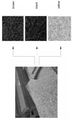
- Figure 2 is an exemplary view of the color development of natural granite using the color development method of Figure 1;
- 3 is an exemplary view showing color development deviation according to the color development test result of the present invention.
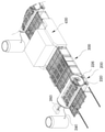
- FIG. 4 is a schematic view showing the structure of an inline type color developing device of the present invention.
- FIG. 5 is a side structural view of FIG. 4
- FIG. 6 is a detailed structural diagram of FIG. 4
- FIG. 10 is an operation structural diagram of the coloring part of FIG. 9
- FIG. 11 is a detailed structural diagram of the heating unit of the present invention.
- FIG. 12 is a structural diagram showing another embodiment of the heating unit of the present invention.
- FIG. 13 is a detailed structural diagram of the cooling unit of the present invention.
- the best mode for carrying out the present invention is a material supply step of supplying granite cut to a certain size on an in-line transfer unit, immersing the granite in a metal salt composition solution, and applying pressure to allow the solution to penetrate into the granite.
- a heating step of heating and drying the colored granite by applying heat to the colored granite in the coloring step a cooling step of blowing air to the heated and dried granite using a blower, immersing the granite in a neutralizing agent and then applying pressure to neutralize it
- a neutralization step in which I penetrate this granite a second heating step of heating and drying the colored granite by applying heat to the granite colored in the neutralization step, and a second cooling step of blowing the heated and dried granite with a blower.
- the coloring step includes a coloring preparation step of individually inserting the granite into the accommodating space of the pressure chamber, immersing the granite by injecting a solution into the accommodating space of the pressure chamber, and then applying pressure to the granite. It consists of a penetration step of coloring the solution, a discharge step of draining the solution in the pressure chamber, releasing the pressure applied, and then withdrawing the granite from the pressure chamber.
- the material supply step, the coloring step, the heating step, the cooling step, the neutralization step, the second heating step, and the second cooling step are sequential in an in-line structure using a conveying element that is a belt or roller operated by a drive motor. It is designed to continuously perform color development in a single state by supply.
- the present invention transports granite in-line so that the granite can be individually colored, and a transfer unit for automatically moving products between color development processes, and an arbitrary position of the transfer unit to perform the coloring process in-line.
- the door is opened and closed to the pressure chamber, and the cut granite in the cut stone state is individually supplied, the solution is filled in the inner space of the pressure chamber, and then pressure is applied so that the granite is seated.
- the heating device is equipped with near-infrared lamps at the top and bottom of the transfer element to individually heat and dry the granite, and then cool the granite through the cooling unit, so that the color of the granite is made in the in-line automation line.
- the color development method of natural granite for construction of the present invention includes a material supply step (S100) of supplying a raw granite stone, a coloring step of using a solution to color the granite (S200), and the coloring step It may be configured to include a heating step (S300) of applying heat to the granite and a cooling step (S400) of lowering the temperature of the granite.
- a neutralization step of injecting a neutralizing agent and using pressure to neutralize the components remaining in the stone ( S500), and a second heating step (S600) of applying heat to the granite and a second cooling step (S700) of cooling may be further included.
- the material supply step ( S100 ) is a step of supplying a granite to be colored on the transfer unit of the inline device, and a cut stone cut to a predetermined size is supplied.
- the cut stone cut from granite can be cut to a size close to 600mm*1800mm, which is the standard stone size of 1 pyeong, or it can be supplied.
- the sebum supplied in the material supply step (S100) is supplied to the coloring step (S200) to be colored.
- the solution is injected to immerse the granite in the solution, and then pressure is applied to allow the solution to permeate into the granite.
- the solution can be used by appropriately mixing and stirring mineral inorganic materials such as iron, chromium, zinc, copper, etc. according to the color, and by adjusting the content of each component according to the color to be developed to form a metal salt composition, FIG. As shown in , it is possible to develop colors in various colors (eg, brown, black, yellow, etc.).
- the penetration depth through which the composition penetrates into the granite can be further increased. You can make it fade and let the color develop.
- the coloring step (S200) includes the coloring preparation step (S220) of individually inserting the granite into the receiving space of the pressure chamber, and the solution to the granite by injecting the solution into the receiving space of the pressure chamber to immerse the granite and then applying pressure to the granite. It consists of a penetration step (S240) of coloring the granite in the pressure chamber and a discharge step (S260) of draining the solution in the pressure chamber and releasing the applied pressure, and then withdrawing the granite from the pressure chamber. Continuous individual production can be achieved.
- the heating step (S300) is a step of heating and drying the granite by applying heat, and is a step for increasing the coloring or color development effect.
- the surface of the individually supplied granite is heated.
- a method of heating after inserting the granite into the chamber or heating using a near-infrared lamp may be used.
- the cooling step (S400) is a step of cooling the heated and dried granite by blowing air, and may be configured to cool the granite by installing a blower and discharging air through a plurality of nozzles.
- the granite colored through this process may be subjected to a neutralization process in order to effectively neutralize the minute residual solution components or residual alkali.
- a second cooling step (S700) of blowing air to the heated and dried granite using a blower may be included to achieve neutralization.
- the material supply step (S100), the coloring step (S200), the heating step (S300), the cooling step (S400), the neutralization step (S500), the second heating step (S600), the second cooling step (S700) is a driving motor
- an in-line structure using a belt or roller operated by a granite it is possible to efficiently develop color of granite with a simple process by allowing color development to be continuously performed individually by sequential supply.
- Test 1 Test 2
- Test 3 Test 4 washing method washing with water washing with water washing with water washing with water washing with water heating temperature 230°C 230°C 230°C 230°C cooling temperature ⁇ 40°C ⁇ 40°C ⁇ 40°C ⁇ 40°C vacuum time 1 min 10 minutes 15 minutes 20 minutes result X(NG) Inadequate usually Great
- the present invention is a structure for implementing a color development method of natural granite for construction, and an in-line type color developing device according to a preferred embodiment of the present invention. developed, and its structure is described in detail as follows.
- the in-line type color development apparatus of the present invention includes a transfer unit 100 for automatically moving products between color development processes while transporting granite in-line, and the coloring process is performed in-line. It may be configured to include a coloring unit 200 configured at an arbitrary position of the conveying unit, and a heating unit 300 and a cooling unit 400 disposed in the next order of the coloring unit on the conveyance path of the conveying unit, In order to neutralize the granite in the formed state, it may be configured to further include a neutralizing unit 500 , a second heating unit 600 , and a second cooling unit 700 after coloring.
- the transfer unit 100 is capable of transferring granite by a transfer element 120 operated by a driving motor, and the transfer element 120 is composed of a plurality of rollers operated by a driving motor, or It may be composed of a conveyor belt or the like for transferring each process in connection.
- the conveying element 120 is configured to be configured to be mounted on the supply plate 140 with a plurality of rollers 122 so that the rollers rotate while individually conveying the cut stone, which is the cut granite, individually, and the colored part 220 ), the transfer element 120 is configured to be positioned in contact with the pressure chamber 220 so that forward supply can be made.
- the supply plate 140 may be disposed at a connection portion connecting each process to guide the granite to the next-order process, and among the supply plate 140 , the supply plate is located at the initial supply portion of the process for developing the natural granite color. As shown in FIG. 7, the supply plate 140 is rotated by the rotation means 144 in a state in which the supply plate 140 is mounted on the stand 142, and the holder 146 is integrally formed on one side thereof. By forming, as shown in FIG. 8, the granite that has been transported on the pallet (P) can be towed individually and then automatically supplied.
- the supply plate 140 has a stand 142 mounted on the rail 160 to enable slide operation or transport, thereby sequentially transporting several granites loaded on a pallet without using manpower to ensure continuous supply. can make it happen.
- the colored part 200 is configured with a cylindrical pressure chamber 220 so that granite can be supplied and accommodated, and a door 222 is provided on one side of the pressure chamber 220.
- the granite which is formed to be colored, can be placed in the receiving space inside the pressure chamber 220 by putting the granite.
- the pressure chamber 220 has a cylindrical structure and can be configured to inject granite through a rounded sidewall. It can be cut to 600mm*1800mm or a size close to it so that individual processes can be performed.
- the length of the inline equipment such as the coloring part 200, the heating part 300, and the cooling part 400 is reduced by allowing it to enter in a relatively long longitudinal direction (1800 mm) in a limited space.
- the equipment can be configured compactly, the time required for the process can be shortened and the productivity can be greatly improved.
- a solution which is a metal salt composition, which is a component for coloring granite, is injected into the pressure chamber 220 , and pressure is injected so that the composition can penetrate deep into the granite.
- a solution line 240 for injecting a solution into the pressure chamber 220 and a pressure line 260 for injecting and discharging pressure may be connected.
- the solution line 240 is connected to the solution tank in which the metal salt composition is stored so that the solution is supplied, and a supply line for supplying the solution into the pressure chamber 220 and a discharge for discharging the solution from the pressure chamber 220 . It may be divided into lines, in which case the discharge line may be configured to discharge the solution by forming a drain at one end of the pressure chamber 220 .
- the pressure line 260 may be connected to a compressor for applying pressure by injecting air into the pressure chamber 220 and an air tank for discharging internal air, and the pressure chamber is filled with a solution and granite is immersed in it. By applying pressure in the granite, the metal salt composition can penetrate into the granite to be colored.
- the door 222 formed in the pressure chamber 220 can be opened and closed in a hinge structure or in a slide structure.
- the door 222 is sealed. It is formed to have a structure to prevent leakage of solution and air.
- the pressure chamber 220 is connected to the door 222 that is opened and closed at one end of the cylindrical structure in order to reduce the amount of solution filled in the receiving space for immersing the granite and to shorten the pressure injection time and the slot space 224. It is possible to perform the coloring process after the granite is placed horizontally by laying the granite in the granite state by forming a granite, and after the granite is individually supplied, the solution is filled in the inner space of the pressure chamber, and then the granite is seated on the granite by applying pressure. can make it happen
- the upper and lower portions of the slot space 224 in which the granite is embedded in the pressure chamber 220 are clogged to minimize the internal space, so that the coloring time is significantly reduced because it is possible to quickly color with only a minimum amount of solution and a minimum amount of air. can be shortened.
- the metal salt composition can be well permeated into the interior of the granite, and the clogging part inside the pressure chamber 220, that is, the space in which the granite is accommodated.
- a separate lifting device or an insertion and withdrawal device may be further formed as a means for entering the granite into the slot space 224 , or a separate transfer roller may be mounted inside the slot space 224 .
- the pressure chamber 220 is mounted so as to be axially rotatable by the rotating unit 226, and the pressure chamber 220 reciprocates in the forward or reverse direction on the transfer unit 100 to change the direction in which the granite enters and exits.
- the pressure chamber 220 reciprocates in the forward or reverse direction on the transfer unit 100 to change the direction in which the granite enters and exits.
- the coloring process is performed, the solution and air in the pressure chamber 220 are discharged, and the discharge direction is switched to the other side when the granite is discharged. It is possible to minimize the volume and to make the equipment line short.
- the rotating part 226 is to be able to rotate the pressure chamber 220 in various ways, such as an axial method or a roller method. As shown in FIG. 10, the pressure chamber 220 is positioned on the rotating roller and then the rotating roller is rotated so that the direction is changed by rotating in the coupled state, and the pressure chamber 220 is rotated while the door
- the opening/closing direction can be switched to forward and reverse.
- the heating unit 300 is equipped with a heating device 320 on the conveying unit 100 for transferring the granite, and the heating unit 320 is a colored part ( 200), near-infrared lamps 322 close to the upper and lower surfaces of the granite are mounted, so that the granite is individually heated and dried, as well as the heating time can be shortened.
- the heating unit 300 forms the heating device 320 in a multi-layer structure, and by mounting the near-infrared lamp 322 on each layer of the heating device 320, respectively, the production efficiency can be improved.
- the transfer element 120 of the transfer unit 100 is configured to be branched by a belt or roller, so that the granite is alternately transferred to each layer of the multi-layer structure to achieve simultaneous heating.
- the multi-layered heating device 320 by making the multi-layered heating device 320 so that the distance between each layer is disposed adjacent to each other, heat loss due to heat transfer between the upper and lower layers is minimized, and heat preservation efficiency is increased, so that the heating is efficient in a short time with relatively low heat transfer cost. This becomes possible.
- the granite heated by the heating unit 300 is transferred to the cooling unit 400 by the conveying unit 100 to be cooled, and the cooling unit 400 discharges air through the blower to the heating unit ( 300) to cool the heated granite.
- the cooling unit 400 is formed to allow blowing through the blower 420 , and a plurality of air nozzles 440 are mounted to blow air evenly on the surface of the granite to achieve cooling.
- the granite colored in the in-line process may be further configured with a neutralizer process, and the neutralizer process may be performed after the granite is cooled in the transfer unit 100 via the cooling unit 400 . have.
- the neutralizing unit 500, the second heating unit 600, and the second cooling unit 700 may be further formed for the neutralizing agent process, the neutralizing unit 500, the second heating unit 600,
- the device configuration of the second cooling unit 700 may be composed of devices of the same principle corresponding to the coloring unit 220 , the heating unit 300 , and the cooling unit 400 , respectively.
- the neutralization unit 500 is configured as a cylindrical pressure chamber so that granite can be supplied and accommodated.
- a door is formed on one side of the pressure chamber to put granite in the receiving space inside the pressure chamber to be colored.
- Granite which is a rough stone, can be placed.
- a neutralizing agent solution is injected into the pressure chamber formed in the neutralizing unit 500 to remove the components remaining in the granite, and pressure is injected so that the neutralizing agent penetrates deep into the granite to remove the remaining components.
- a solution line for injecting a neutralizing agent and a pressure line for injecting and discharging pressure may be connected to the pressure chamber.
- the solution line can be divided into a supply line for supplying the neutralizing agent into the pressure chamber and a discharge line for discharging the neutralizing agent containing residual substances from the pressure chamber. It may be configured to discharge the used neutralizing agent.
- the pressure line may be connected to a compressor for applying pressure by injecting air into the pressure chamber, and an air tank for discharging internal air, and a neutralizing agent by applying pressure in a state in which the neutralizing agent is filled in the pressure chamber and the granite is immersed. can penetrate deep into the granite to remove residual components.
- the pressure chamber of the neutralization unit may be formed to correspond to the structure of the pressure chamber of the coloring unit, and by forming the door opening/closing structure or the internal structure of the chamber to correspond to the structure, the neutralization performance can be improved by effectively pressurizing the pressure into the chamber.
- the pressure chamber reciprocates in the forward or reverse direction by the rotating unit to change the direction in which the granite enters and exits, thereby performing the neutralization process while the conveying unit 100 repeatedly conveys the granite in the forward direction.
- the neutralization process is performed, and after discharging the solution and air from the pressure chamber, the discharge direction is switched to the other side when the granite is discharged, thereby reducing the volume of the automation line. It is possible to minimize and shorten the equipment line.
- the rotating part may be configured in the same way as the rotating method of the pressure chamber of the coloring part, and a detailed description thereof will be omitted.
- the second heating unit 600 is equipped with a heating device in the conveying unit 100 for conveying the granite, and the heating unit is the upper end and the lower end of the conveying element operated by the driving motor. , a near-infrared lamp close to the lower surface is mounted, so that the granite can be individually heated and dried.
- the heating device of the second heating unit 600 is also formed in a multi-layer structure corresponding thereto.
- the production efficiency can be improved by mounting a near-infrared lamp on each layer of the heating device, respectively.
- the granite heated by the second heating unit 600 is transferred to the second cooling unit 700 by the conveying unit 100 to be cooled, and the second cooling unit 700 receives air through the blower. By discharging, the granite heated in the second heating unit is cooled.
- the second cooling unit 700 is formed to allow blowing through the blower, and a plurality of air nozzles are mounted to blow air evenly on the surface of the granite to achieve cooling.
Landscapes
- Chemical & Material Sciences (AREA)
- Engineering & Computer Science (AREA)
- Ceramic Engineering (AREA)
- Materials Engineering (AREA)
- Structural Engineering (AREA)
- Organic Chemistry (AREA)
- Inorganic Chemistry (AREA)
- Physics & Mathematics (AREA)
- Thermal Sciences (AREA)
- Health & Medical Sciences (AREA)
- Toxicology (AREA)
- Optical Filters (AREA)
- Drying Of Solid Materials (AREA)
- Application Of Or Painting With Fluid Materials (AREA)
Abstract
Applications Claiming Priority (2)
| Application Number | Priority Date | Filing Date | Title |
|---|---|---|---|
| KR10-2020-0090635 | 2020-07-21 | ||
| KR1020200090635A KR102384389B1 (ko) | 2020-07-21 | 2020-07-21 | 건축용 천연 화강석의 발색방법 및 인라인 타입 발색장치 |
Publications (1)
| Publication Number | Publication Date |
|---|---|
| WO2022019617A1 true WO2022019617A1 (fr) | 2022-01-27 |
Family
ID=79729895
Family Applications (1)
| Application Number | Title | Priority Date | Filing Date |
|---|---|---|---|
| PCT/KR2021/009347 Ceased WO2022019617A1 (fr) | 2020-07-21 | 2021-07-20 | Procédé de développement de couleur dans du granit naturel pour la construction, et dispositif de développement de couleur de type en ligne |
Country Status (2)
| Country | Link |
|---|---|
| KR (1) | KR102384389B1 (fr) |
| WO (1) | WO2022019617A1 (fr) |
Cited By (1)
| Publication number | Priority date | Publication date | Assignee | Title |
|---|---|---|---|---|
| CN114778410A (zh) * | 2022-04-24 | 2022-07-22 | 西安石油大学 | 一种岩石孔隙结构的化验设备 |
Citations (5)
| Publication number | Priority date | Publication date | Assignee | Title |
|---|---|---|---|---|
| KR100875202B1 (ko) * | 2008-05-19 | 2008-12-19 | 재단법인 거창화강석연구센터 | 친환경 기능성 석재, 이의 제조방법 및 친환경 기능성석재의 제조장치 |
| KR20110129779A (ko) * | 2010-05-26 | 2011-12-02 | 김진태 | 내,외장재용 칼라 대리석의 제조방법 |
| KR20120083771A (ko) * | 2011-01-18 | 2012-07-26 | 주식회사 아이엔씨테크 | 화강암 염색방법 |
| KR20140142431A (ko) * | 2013-06-03 | 2014-12-12 | 대림아이앤에스주식회사 | 진공유리 제조장치 및 이를 이용한 진공유리 제조방법 |
| KR20160066787A (ko) * | 2014-12-03 | 2016-06-13 | 고륜석업 주식회사 | 건축용 석재의 착색방법 |
Family Cites Families (3)
| Publication number | Priority date | Publication date | Assignee | Title |
|---|---|---|---|---|
| KR200181777Y1 (ko) * | 1995-01-25 | 2000-10-02 | 장용균 | 인덱스 카드 공급장치 |
| JP2003306387A (ja) * | 2002-04-11 | 2003-10-28 | Tokyo Yogyo Co Ltd | 焼成用セッター及びその製造方法 |
| KR101591724B1 (ko) * | 2014-11-18 | 2016-02-04 | 주식회사 우리시스템 | 칩형 전자부품용 자동 로딩 시스템 |
-
2020
- 2020-07-21 KR KR1020200090635A patent/KR102384389B1/ko active Active
-
2021
- 2021-07-20 WO PCT/KR2021/009347 patent/WO2022019617A1/fr not_active Ceased
Patent Citations (5)
| Publication number | Priority date | Publication date | Assignee | Title |
|---|---|---|---|---|
| KR100875202B1 (ko) * | 2008-05-19 | 2008-12-19 | 재단법인 거창화강석연구센터 | 친환경 기능성 석재, 이의 제조방법 및 친환경 기능성석재의 제조장치 |
| KR20110129779A (ko) * | 2010-05-26 | 2011-12-02 | 김진태 | 내,외장재용 칼라 대리석의 제조방법 |
| KR20120083771A (ko) * | 2011-01-18 | 2012-07-26 | 주식회사 아이엔씨테크 | 화강암 염색방법 |
| KR20140142431A (ko) * | 2013-06-03 | 2014-12-12 | 대림아이앤에스주식회사 | 진공유리 제조장치 및 이를 이용한 진공유리 제조방법 |
| KR20160066787A (ko) * | 2014-12-03 | 2016-06-13 | 고륜석업 주식회사 | 건축용 석재의 착색방법 |
Cited By (1)
| Publication number | Priority date | Publication date | Assignee | Title |
|---|---|---|---|---|
| CN114778410A (zh) * | 2022-04-24 | 2022-07-22 | 西安石油大学 | 一种岩石孔隙结构的化验设备 |
Also Published As
| Publication number | Publication date |
|---|---|
| KR102384389B1 (ko) | 2022-04-08 |
| KR20220011553A (ko) | 2022-01-28 |
Similar Documents
| Publication | Publication Date | Title |
|---|---|---|
| US4522581A (en) | System for handling partly finished workpieces | |
| KR101750261B1 (ko) | 곡면 윈도우 글라스 제조장치 및 이를 이용한 곡면글라스 제조방법 | |
| WO2022019617A1 (fr) | Procédé de développement de couleur dans du granit naturel pour la construction, et dispositif de développement de couleur de type en ligne | |
| US3662996A (en) | Multi-chamber carburizing apparatus | |
| WO2022215790A1 (fr) | Système de revêtement uv de couvercle arrière de téléphone mobile | |
| TWI892251B (zh) | 塗敷裝置、乾燥裝置、光照射裝置以及塗敷系統 | |
| JP2003229355A (ja) | 基板搬送処理装置 | |
| KR100816647B1 (ko) | 인라인 타입의 큐어장치 | |
| WO2024117436A1 (fr) | Système de traitement thermique continu pour récipient de stockage de fluide à haute pression | |
| JP2003068725A (ja) | 加熱処理装置 | |
| CN211517809U (zh) | 一种木板表面做旧染色自动化处理线 | |
| US4851022A (en) | Method and oven for ceramising glass plates | |
| WO2018092952A1 (fr) | Système de mise en forme 3d et appareil de post-traitement pour objet en 3d | |
| CN113473736A (zh) | 氮气密闭烘烤机台及基板进出烘烤装置的方法 | |
| KR100283553B1 (ko) | 밀폐형 콘베이어 인쇄회로기판 건조장치 | |
| JP3724645B2 (ja) | 環境試験装置 | |
| JP2589823Y2 (ja) | 連続焼入装置 | |
| JPH0740525A (ja) | 印刷装置 | |
| CN120888749A (zh) | 一种齿轮热处理系统及处理工艺 | |
| CN119595696B (zh) | 陶瓷大板抗热震检测线 | |
| CN112153815B (zh) | 烘烤设备 | |
| JPS6230935A (ja) | さらしテスト装置 | |
| SU1178379A1 (ru) | Способ обработки внутренних поверхностей хлебопекарных форм и лини дл обработки внутренних поверхностей хлебопекарных форм | |
| JPH1052808A (ja) | 無機系押し出し成形体の乾燥方法及び装置 | |
| TWI335637B (fr) |
Legal Events
| Date | Code | Title | Description |
|---|---|---|---|
| 121 | Ep: the epo has been informed by wipo that ep was designated in this application |
Ref document number: 21845559 Country of ref document: EP Kind code of ref document: A1 |
|
| NENP | Non-entry into the national phase |
Ref country code: DE |
|
| 122 | Ep: pct application non-entry in european phase |
Ref document number: 21845559 Country of ref document: EP Kind code of ref document: A1 |
|
| 32PN | Ep: public notification in the ep bulletin as address of the adressee cannot be established |
Free format text: NOTING OF LOSS OF RIGHTS PURSUANT TO RULE 112(1) EPC (EPO FORM 1205A DATED 07/07/2023) |
|
| 122 | Ep: pct application non-entry in european phase |
Ref document number: 21845559 Country of ref document: EP Kind code of ref document: A1 |