WO2022039218A1 - ブロー成形装置 - Google Patents
ブロー成形装置 Download PDFInfo
- Publication number
- WO2022039218A1 WO2022039218A1 PCT/JP2021/030353 JP2021030353W WO2022039218A1 WO 2022039218 A1 WO2022039218 A1 WO 2022039218A1 JP 2021030353 W JP2021030353 W JP 2021030353W WO 2022039218 A1 WO2022039218 A1 WO 2022039218A1
- Authority
- WO
- WIPO (PCT)
- Prior art keywords
- mold
- blow
- mold clamping
- blow molding
- clamping plate
- Prior art date
- Legal status (The legal status is an assumption and is not a legal conclusion. Google has not performed a legal analysis and makes no representation as to the accuracy of the status listed.)
- Ceased
Links
Images


Classifications
-
- B—PERFORMING OPERATIONS; TRANSPORTING
- B29—WORKING OF PLASTICS; WORKING OF SUBSTANCES IN A PLASTIC STATE IN GENERAL
- B29C—SHAPING OR JOINING OF PLASTICS; SHAPING OF MATERIAL IN A PLASTIC STATE, NOT OTHERWISE PROVIDED FOR; AFTER-TREATMENT OF THE SHAPED PRODUCTS, e.g. REPAIRING
- B29C49/00—Blow-moulding, i.e. blowing a preform or parison to a desired shape within a mould; Apparatus therefor
- B29C49/42—Component parts, details or accessories; Auxiliary operations
- B29C49/56—Opening, closing or clamping means
- B29C49/5605—Hydraulically operated, i.e. closing or opening of the mould parts is done by hydraulic means
-
- B—PERFORMING OPERATIONS; TRANSPORTING
- B29—WORKING OF PLASTICS; WORKING OF SUBSTANCES IN A PLASTIC STATE IN GENERAL
- B29C—SHAPING OR JOINING OF PLASTICS; SHAPING OF MATERIAL IN A PLASTIC STATE, NOT OTHERWISE PROVIDED FOR; AFTER-TREATMENT OF THE SHAPED PRODUCTS, e.g. REPAIRING
- B29C49/00—Blow-moulding, i.e. blowing a preform or parison to a desired shape within a mould; Apparatus therefor
- B29C49/02—Combined blow-moulding and manufacture of the preform or the parison
- B29C2049/023—Combined blow-moulding and manufacture of the preform or the parison using inherent heat of the preform, i.e. 1 step blow moulding
-
- B—PERFORMING OPERATIONS; TRANSPORTING
- B29—WORKING OF PLASTICS; WORKING OF SUBSTANCES IN A PLASTIC STATE IN GENERAL
- B29C—SHAPING OR JOINING OF PLASTICS; SHAPING OF MATERIAL IN A PLASTIC STATE, NOT OTHERWISE PROVIDED FOR; AFTER-TREATMENT OF THE SHAPED PRODUCTS, e.g. REPAIRING
- B29C49/00—Blow-moulding, i.e. blowing a preform or parison to a desired shape within a mould; Apparatus therefor
- B29C49/42—Component parts, details or accessories; Auxiliary operations
- B29C49/56—Opening, closing or clamping means
- B29C2049/563—Clamping means
-
- B—PERFORMING OPERATIONS; TRANSPORTING
- B29—WORKING OF PLASTICS; WORKING OF SUBSTANCES IN A PLASTIC STATE IN GENERAL
- B29C—SHAPING OR JOINING OF PLASTICS; SHAPING OF MATERIAL IN A PLASTIC STATE, NOT OTHERWISE PROVIDED FOR; AFTER-TREATMENT OF THE SHAPED PRODUCTS, e.g. REPAIRING
- B29C49/00—Blow-moulding, i.e. blowing a preform or parison to a desired shape within a mould; Apparatus therefor
- B29C49/42—Component parts, details or accessories; Auxiliary operations
- B29C49/56—Opening, closing or clamping means
- B29C2049/566—Locking means
- B29C2049/5661—Mechanical
- B29C2049/5664—Translating locking pin
-
- B—PERFORMING OPERATIONS; TRANSPORTING
- B29—WORKING OF PLASTICS; WORKING OF SUBSTANCES IN A PLASTIC STATE IN GENERAL
- B29C—SHAPING OR JOINING OF PLASTICS; SHAPING OF MATERIAL IN A PLASTIC STATE, NOT OTHERWISE PROVIDED FOR; AFTER-TREATMENT OF THE SHAPED PRODUCTS, e.g. REPAIRING
- B29C2949/00—Indexing scheme relating to blow-moulding
- B29C2949/07—Preforms or parisons characterised by their configuration
- B29C2949/0715—Preforms or parisons characterised by their configuration the preform having one end closed
-
- B—PERFORMING OPERATIONS; TRANSPORTING
- B29—WORKING OF PLASTICS; WORKING OF SUBSTANCES IN A PLASTIC STATE IN GENERAL
- B29C—SHAPING OR JOINING OF PLASTICS; SHAPING OF MATERIAL IN A PLASTIC STATE, NOT OTHERWISE PROVIDED FOR; AFTER-TREATMENT OF THE SHAPED PRODUCTS, e.g. REPAIRING
- B29C49/00—Blow-moulding, i.e. blowing a preform or parison to a desired shape within a mould; Apparatus therefor
- B29C49/02—Combined blow-moulding and manufacture of the preform or the parison
- B29C49/06—Injection blow-moulding
- B29C49/061—Injection blow-moulding with parison holding means displaceable between injection and blow stations
- B29C49/062—Injection blow-moulding with parison holding means displaceable between injection and blow stations following an arcuate path, e.g. rotary or oscillating-type
-
- B—PERFORMING OPERATIONS; TRANSPORTING
- B29—WORKING OF PLASTICS; WORKING OF SUBSTANCES IN A PLASTIC STATE IN GENERAL
- B29C—SHAPING OR JOINING OF PLASTICS; SHAPING OF MATERIAL IN A PLASTIC STATE, NOT OTHERWISE PROVIDED FOR; AFTER-TREATMENT OF THE SHAPED PRODUCTS, e.g. REPAIRING
- B29C49/00—Blow-moulding, i.e. blowing a preform or parison to a desired shape within a mould; Apparatus therefor
- B29C49/42—Component parts, details or accessories; Auxiliary operations
- B29C49/64—Heating or cooling preforms, parisons or blown articles
- B29C49/6409—Thermal conditioning of preforms
- B29C49/6427—Cooling of preforms
Definitions
- the present invention relates to a blow molding apparatus.
- a stretch blow molding method has been known as one of the methods for manufacturing a resin container.
- the preform placed in the split mold (blow mold) corresponding to the shape of the container is stretched in the vertical direction of the container, and the preform is expanded in the horizontal direction by the pressure of the gas blown into the preform. And shape it into the shape of the container.
- the mold clamping force is applied to the blow split mold by pressing the mold clamping plate to which the blow split mold is fixed with the hydraulic piston.
- the position of the hydraulic piston with respect to the mold clamping plate is fixed, the molding space in the blow split mold and the blow split mold fixed to the mold clamping plate varies depending on the specifications of the container to be manufactured. That is, the position and dimensions of the container (projected on the mold clamping plate) with respect to the mold clamping plate can vary greatly from container to container.
- the mold clamping plate bends and the upper and lower ends of the blow split mold are easily opened. It ends up.
- Patent Document 1 proposes a mold opening prevention mechanism that opens and closes in a direction orthogonal to the opening / closing direction of the blow split mold, and sandwiches and restrains the side surface of the blow split mold that is closed from the outside.
- the present invention has been made in view of such a problem, and has a space-saving and relatively inexpensive configuration, and can suppress the opening of various blow-split molds without requiring complicated adjustment work.
- the purpose is to provide the device.
- the blow molding apparatus manufactures a resin container by blow molding a bottomed tubular preform.
- the blow molding device drives a pair of mold clamping plates that openably support a pair of blow split molds accommodating preforms and a pair of mold clamping plates in the opening and closing direction, and the mold clamping force is applied to the mold clamping plates when the mold is closed. It is provided with a linear motion mechanism for adding a mold, and a lock member that interferes with the lower end side of the mold clamping plate at the mold closing position of the blow split mold and regulates the movement of the mold clamping plate in the mold opening direction.
- FIG. 1 It is a figure which shows typically the structure of the blow molding apparatus of this embodiment. It is a front view which shows the structural example of the blow molding part in the mold open state. It is a front view which shows the structural example of the blow molding part in a mold closed state.
- (A) is a side view showing a locked portion in an unlocked state
- (b) is a side view showing a locked portion in a locked state. It is an enlarged view of the lock part in the locked state.
- It is a flowchart which shows the process of the manufacturing method of a container. It is a graph which shows an example of the simulation of the mold opening amount and the piston height in a blow cavity split mold.
- (A) to (C) are diagrams schematically showing a modified example of the blow molding apparatus.
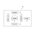
- FIG. 1 is a diagram schematically showing the configuration of the blow molding apparatus 20 of the present embodiment.
- the blow molding apparatus 20 of the present embodiment is a hot parison method (also referred to as a one-stage method) in which a container is blow-molded by utilizing the retained heat (internal heat amount) at the time of injection molding without cooling the preform 11 to room temperature. It is a device.
- the blow molding device 20 shown in FIG. 1 includes an injection molding unit 21, a temperature adjusting unit 22, a blow molding unit 23, a take-out unit 24, and a transport mechanism 26.
- the injection molding unit 21, the temperature adjusting unit 22, the blow molding unit 23, and the take-out unit 24 are arranged at positions rotated by a predetermined angle (for example, 90 degrees) about the transport mechanism 26.
- the transport mechanism 26 includes a rotating plate (not shown) that rotates about an axis in the direction perpendicular to the paper surface of FIG. 1. On the rotating plate, one or more neck types (not shown in FIG. 1) holding the neck of a preform or resin container (hereinafter, simply referred to as a container) are arranged at each predetermined angle. By rotating the rotating plate, the transport mechanism 26 transports the preform (or container) whose neck is held by the neck type in the order of the injection molding section 21, the temperature control section 22, the blow molding section 23, and the take-out section 24. do.
- the transport mechanism 26 can also raise and lower the rotary plate, and also performs operations related to mold closing and mold opening (release) of the preform in the injection molding unit 21.
- the injection molding unit 21 includes an injection cavity type and an injection core type, which are not shown, respectively, and manufactures a preform.
- An injection device 25 that supplies a resin material that is a raw material of the preform 11 is connected to the injection molding unit 21.
- the injection cavity type and the injection core type and the neck type of the transport mechanism 26 are closed to form a preform-shaped mold space. Then, by pouring the resin material from the injection device 25 into such a preform-shaped mold space, the injection molding unit 21 manufactures the preform.
- the overall shape of the preform is a bottomed cylindrical shape in which one end side is open and the other end side is closed. A neck is formed at the open end of the preform.
- the material of the container and the preform is a thermoplastic synthetic resin, and can be appropriately selected according to the use of the container.
- specific types of materials include, for example, PET (polyethylene terephthalate), PEN (polyethylene naphthalate), PCTA (polycyclohexanedimethylene terephthalate), Tritan (Tritan (registered trademark): copolyester manufactured by Eastman Chemical Co., Ltd.).
- PP polyethylene
- PE polyethylene
- PC polyyester
- PES polyether sulfone
- PPSU polyphenyl sulfone
- PS polyyester
- COP / COC cyclic olefin polymer
- PMMA polymethacrylic acid
- Methyl: acrylic acrylic
- PLA polylactic acid
- the neck mold of the transport mechanism 26 is not opened and the preform is held and conveyed as it is.
- the number of preforms simultaneously molded by the injection molding unit 21 (that is, the number of containers that can be simultaneously molded by the blow molding apparatus 20) can be appropriately set.
- the temperature control unit 22 has a mold unit for temperature control, including a cavity type (temperature control pot or heating pot) capable of accommodating a preform.
- the temperature adjusting unit 22 performs temperature equalization and uneven temperature removal of the preform produced by the injection molding unit 21, and sets the temperature of the preform to a temperature suitable for blow molding (for example, about 90 ° C to 105 ° C) and shaping. Adjust to have a temperature distribution suitable for the shape of the container to be molded.
- the temperature adjusting unit 22 also has a function of cooling the preform in a high temperature state after injection molding.
- blow molding unit 23 performs stretch blow molding on the preform whose temperature has been adjusted by the temperature adjusting unit 22, and manufactures a container.
- FIG. 2 is a front view showing a configuration example of the blow molding unit 23 in the mold open state
- FIG. 3 is a front view showing a configuration example of the blow molding unit 23 in the mold closed state.
- the blow molding unit 23 includes a blow cavity split mold 31, a mold clamping plate 32, a linear motion mechanism 33, and a lock portion 34, respectively.
- the blow cavity split mold 31, the mold clamping plate 32, and the linear motion mechanism 33 are installed on the machine base 30, and the lock portion 34 is installed on the lower side of the machine base 30.
- the blow molding unit 23 further includes a vertical axis stretching member having a stretching rod, an air introducing member having a blow core, and a bottom mold.
- the air introduction member is arranged above the mold closed position of the blow cavity split mold 31 and is inserted into the preform (or the air introduction member abuts on the upper surface of the preform).
- the bottom mold is a mold that defines the shape of the bottom surface of the container, and is arranged so as to be able to move up and down below the mold closed position of the blow cavity split mold 31.
- the pair of blow cavity split molds 31 is a mold material having a molding space (cavity) that defines the shape of the container.
- the blow cavity split mold 31 is divided by a parting surface 31a along the vertical direction (Z direction) of FIGS. 2 and 3, and is configured to be openable and closable in the horizontal direction (Y direction) of FIGS. 2 and 3.
- the blow cavity split mold 31 forms a blow cavity for blow molding a preform (not shown) into a predetermined shape in the mold closed state of FIG.
- the pair of mold clamping plates 32 are arranged so that their first surfaces 32a face each other with the blow cavity split mold 31 interposed therebetween.
- the back surface 31b (the surface opposite to the parting surface 31a) of the blow cavity split mold 31 is fixed to the first surface 32a of the mold clamping plate 32, respectively.
- the blow cavity split mold 31 fixed to the mold clamping plate 32 can be replaced according to the container to be manufactured.
- the moving portion 35 is composed of an oil-impregnated steel material, a linear guide, a roller, or the like.
- a linear motion portion 33a (for example, a piston) described later of the linear motion mechanism 33 is connected to the second surface 32b on the side opposite to the first surface 32a.
- the driving force from the linear motion mechanism 33 is transmitted to the blow cavity split mold 31 via the mold clamping plate 32.
- the linear motion mechanism 33 is an actuator that has a linear motion unit 33a and a drive unit 33b, and advances and retreats the linear motion unit 33a by the power of the drive unit 33b.
- the linear motion mechanism 33 may be configured as, for example, a hydraulic actuator or a pneumatic actuator having a piston and a cylinder, or an electric actuator having a link mechanism (or a ball screw mechanism) and an electric motor.
- the illustrated linear motion mechanism 33a is a hydraulic actuator having a piston as the linear motion unit 33a and a cylinder as the drive unit 33.
- the main body 33c of the linear motion mechanism 33 is fixed on the machine base 30, and the linear motion unit 33a and the drive unit 33b are fixed at a predetermined height in the Z direction.
- the linear motion mechanism 33 linearly moves the linear motion unit 33a in the Y direction under the control of the drive unit 33b, and drives the mold clamping plate 32 in the Y direction.
- the linear motion mechanism 33 presses the blow cavity split mold 31 in the mold closing direction to perform mold clamping.
- the mold clamping force by the linear motion mechanism 33 is set to a size that can prevent the mold from opening with respect to the blow pressure.
- the mounting position of the linearly moving portion 33a in the mold clamping plate 32 in the height direction (Z direction) is from the center position S of the second surface 32b (XZ plane) of the mold clamping plate 32. Is also set on the upper side (see FIG. 4).
- the blow molding apparatus 20 is provided with a plurality of models (lineups) whose machine specifications are optimized for each molding application (dimensions and types of containers to be molded) while considering versatility. And, conventionally, it has been designed so that the positional relationship between the mold clamping plate 32 and the linear motion portion 33a is different (properly used) for each model.
- the mounting position of the linear moving portion 33a in the mold clamping plate 32 is on the upper side, and in a model in which many large containers are molded, the mounting position of the linear moving portion 33a in the mold clamping plate 32 is in the center.
- the lock portion 34 which will be described later, the mounting position of the linear motion portion 33a on the mold clamping plate 32 is the center position even in a model corresponding to molding of a large container, for example, regardless of the molding application. It is possible to make it above S.
- the mounting position of the linear motion portion 33a in the height direction is above the position where the lower mold opening amount and the upper mold opening amount of the blow cavity split mold 31 are in equilibrium (P1 in FIG. 7 to be described later).
- the mounting position of the linear motion portion 33a in the height direction may be set to a position where the mold opening amount on the upper side of the blow cavity split mold 31 is equal to or less than the threshold value (Th of FIG. 7 described later).
- the threshold value of the mold opening amount is determined by the specifications of the container and is not particularly limited, but is set to, for example, 0.15 mm or less, preferably 0.1 mm or less.
- the mold clamping force from the linearly moving portion 33a acts strongly on the upper side of the blow cavity split mold 31.
- the mold opening on the upper side of the blow cavity split mold 31 can be effectively suppressed.
- FIG. 4A is a side view showing the locked portion 34 in the unlocked state
- FIG. 4B is a side view showing the locked portion 34 in the locked state
- FIG. 5 is an enlarged view of the lock portion 34 in the locked state.
- the pair of lock portions 34 are arranged at positions corresponding to the mold clamping plate 32 in the mold closed state in the Y direction.
- the pair of lock portions 34 have a function of holding the pair of mold clamping plates 32 in the mold closed state from the outside. Since the configurations of the pair of lock portions 34 are the same, one configuration will be described below, and the duplication of the other will be omitted.
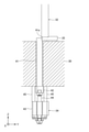
- the lock portion 34 has a lock bar 41, a support 42, a drive member 43 such as an air cylinder, a hydraulic cylinder, and an electric motor, and a fixing member (connecting member, spacer member) 45.
- the lock bar 41 is a stopper member extending in the Z direction, and is inserted into the machine base 30 so as to be able to advance and retreat in the Z direction.
- at least one or more, preferably two or more lock bars 41 are arranged at intervals in the X direction, and the lower end side of each lock bar 41 is fixed to the support 42.
- the lock bar 41 is an example of a lock member.
- the lock bar 41 retracts below the upper surface of the machine base 30. In the unlocked state, the lock bar 41 does not interfere with the moving portion 35 (or the lower end of the mold clamping plate 32), and the mold clamping plate 32 can move in the Y direction.
- the lock bar 41 projects upward from the upper surface of the machine base 30. As a result, the locked lock bar 41 comes into contact with the moving portion 35 (or the lower end of the mold clamping plate 32), whereby the movement of the mold clamping plate 32 in the mold opening direction is restricted by the lock bar 41.
- a wedge-shaped inclined surface 41a inclined so as to narrow toward the upper side is formed at the upper end portion of the lock bar 41.
- the inclined surface 41a of the lock bar 41 is formed at an inward position facing the moving portion 35 (or the lower end of the mold clamping plate 32) in the locked state. Therefore, when the lock bar 41 is moved upward, it is pressed against the inclined surface 41a of the lock bar 41, and a reaction force is generated on the moving portion 35 (or the lower end of the mold clamping plate 32) in the upper side and the mold closing direction. As a result, the lower end side of the mold clamping plate 32 and the blow cavity split mold 31 is more strongly fixed via the moving portion 35 (or the lower end of the mold clamping plate 32).
- the angle of the inclined surface 41a of the lock bar 41 and the angle (tapered angle) of the inclined surface of the moving portion or the lower end of the mold clamping plate 32 that comes into contact with the inclined surface 41a in the locked state are in the mold opening / closing direction from the reaction force to the upper side.
- the reaction force force acting in the horizontal direction
- it may be set to 5 ° to 10 °.
- an inclined surface is provided at the lower end of the lock bar 41, the moving portion 35, or the mold clamping plate 32 for cushioning when the stop position of the blow cavity split mold 31 shifts or the thermal expansion of the blow cavity split mold 31 occurs. ,
- the flexibility in the blow molding unit 23 may be increased.
- the support 42 extends in the X direction and receives at least one, for example, two lower ends of the lock bar 41 (that is, the lower end of the lock bar 41). A member connected to). Further, in the support 42, the tip of the drive rod 44 of the drive member 43 is connected between the two lock bars 41.
- the drive member 43 is attached to the lower side of the machine base 30 via the fixing member 45.
- the drive member 43 advances and retreats the drive rod 44, which is arranged upward and extends in the Z direction.
- the lock bar 41 can be moved back and forth in the Z direction via the support 42 connected to the drive rod 44.
- the fixing member 45 is a member for fixing (connecting) the driving member 43 below the machine base 30.
- the fixing member 45 is composed of, for example, a plurality of rod-shaped members fixed to the lower surface of the machine base 30 and hanging down, and a plate-shaped member fixed to the lower ends (ends) of the plurality of rod-shaped members.
- the drive member 43 is fixed to the lower surface side of the plate-shaped member.
- the fixing member 45 is also arranged to provide a space for the stroke of the drive rod 44 between the drive member 43 and the lower surface of the machine base 30.
- the Z-direction dimension of the fixing member 45 is determined based on the sum of the stroke of the drive rod 44 and the Z-direction dimension of the support 42.
- the take-out unit 24 is configured to open the neck of the container manufactured by the blow molding unit 23 from the neck mold and take out the container to the outside of the blow molding device 20.
- FIG. 6 is an example of a flowchart showing the process of the blow molding method.
- Step S101 Injection molding process
- the resin is injected from the injection device 25 into the preform-shaped mold space formed by the injection cavity type, the injection core type, and the neck type of the transport mechanism 26, and the preform is manufactured.
- the rotating plate of the transfer mechanism 26 rotates by a predetermined angle, and the preform held in the neck mold is transferred to the temperature adjusting unit 22 in a state of containing the heat retained during injection molding.
- Step S102 Temperature adjustment step
- the preform is housed in the mold unit for temperature adjustment, and the temperature is adjusted to bring the temperature of the preform close to the temperature suitable for the final blow.
- the temperature adjusting unit 22 cools the preform with high heat and adjusts the temperature distribution (temperature equalization, removal of uneven temperature, etc.).
- the rotating plate of the transport mechanism 26 rotates by a predetermined angle, and the temperature-adjusted preform held in the neck mold is transported to the blow molding unit 23.
- Step S103 Blow molding process
- the blow molding unit 23 performs blow molding of the container.
- the blow cavity split mold 31 is closed by driving the linear motion portion 33a of the linear motion mechanism 33 to move the mold clamping plate 32, and the conveyed preform is accommodated in the mold space.
- the linear motion portion 33a is boosted to a predetermined pressure to mold the blow cavity split mold 31, and the drive member 43 of the lock portion 34 is operated to raise the lock bar 41. Let me.
- the lock portion 34 is locked, and the movement of the mold clamping plate 32 and the blow cavity split mold 31 in the mold opening direction is restricted by the lock bar 41.
- the air introduction member comes into contact with the neck of the preform.
- the drawing rod vertical stretching member
- blow air is supplied from the air introducing member to laterally spread the preform.
- Axial stretching As a result, the preform is expanded and shaped so as to be in close contact with the mold space of the blow cavity split mold 31, and is blow-molded into the container.
- the bottom mold stands by at a lower position where it does not come into contact with the bottom of the preform before the blow cavity split mold 31 is closed, and is quickly raised to the molding position before or after the mold is closed.
- the linear motion mechanism 33 presses the blow cavity split mold 31 in the mold closing direction via the mold clamping plate 32 to perform mold clamping. Since the linear motion portion 33a of the linear motion mechanism 33 is arranged closer to the upper side of the mold clamping plate 32, the mold clamping force from the linear motion portion 33a strongly acts on the upper side of the blow cavity split mold 31. Therefore, the upper side of the blow cavity split mold 31 is maintained in the mold closed state by the mold clamping force from the linear motion portion 33a, and the mold opening due to the pressure of the blow air is suppressed.
- the lower end side of the mold clamping plate 32 interferes with the lock bar 41 of the lock portion 34, and the movement in the mold opening direction is restricted. Therefore, even if a force in the mold opening direction due to the pressure of the blow air acts on the lower side of the blow cavity split mold 31, the mold closed state is maintained by the reaction force from the lock portion 34. As a result, the mold opening due to the pressure of the blow air is suppressed even on the lower side of the blow cavity split mold 31.
- Step S104 Container removal step
- the drive member 43 of the lock portion 34 is operated to lower the lock bar 41, so that the lock portion 34 is in the unlocked state, and the mold clamping plate 32 and the blow cavity split mold 31 can be moved.
- the blow cavity split mold 31 is opened by driving the linear motion portion 33a of the linear motion mechanism 33 to move the mold clamping plate 32.
- the container can be moved from the blow molding unit 23.
- the rotating plate of the transport mechanism 26 rotates by a predetermined angle, and the container is transported to the take-out unit 24.
- the neck portion of the container is released from the neck mold, and the container is taken out to the outside of the blow molding apparatus 20.
- each time of the injection molding process, the temperature adjustment process, the blow molding process, and the container take-out process has the same length.
- the transport time between each process is the same length.
- the blow molding portion 23 of the present embodiment has a lock portion 34 that interferes with the lower end side of the mold clamping plate 32 at the mold closing position of the blow cavity split mold 31 and restricts the movement of the mold clamping plate 32 in the mold opening direction. ..
- the mold clamping plate 32 at the time of mold clamping is supported at two places above and below the linear motion portion 33a and the lock portion 34 of the linear motion mechanism 33 in the height direction. Both side mold opening can be suppressed.
- the plate thickness of the mold clamping plate 32 and the linear motion mechanism are not increased. I'm done. Therefore, the manufacturing cost of the blow molding apparatus 20 can be suppressed.
- the lock portion 34 of the present embodiment can be used as it is even if it is replaced with a different blow cavity split mold 31 as long as the mold closing position is the same. Therefore, according to the present embodiment, it is possible to suppress the mold opening of various blow cavity split molds 31 without requiring complicated adjustment work.
- the lock portion 34 of the present embodiment is arranged on the lower side of the mold clamping plate 32, it can be attached to the machine base 30 on which the mold clamping plate 32 and the linear motion mechanism 33 are mounted, and the lock portion 34 can be attached. It is also easy to secure a space for advancing and retreating the lock bar 41. For example, if the lock mechanism is arranged on the side of the mold clamping plate 32, the area of the device increases by the space of the lock mechanism, and if the lock mechanism is arranged above the mold clamping plate 32, it interferes with the preform transfer mechanism and the like. It will be necessary to avoid it. Therefore, by arranging the lock portion 34 under the mold clamping plate 32 as in the present embodiment, it is possible to realize space saving of the apparatus.
- the lower mold opening of the blow cavity split mold 31 is suppressed by the lock portion 34, it is not necessary to suppress the lower mold opening by the linear motion portion 33a of the linear motion mechanism 33. That is, when setting the position of the linear motion portion 33a of the linear motion mechanism 33, it is sufficient to consider the mold opening amount on the upper side without considering the mold opening amount on the lower side.
- FIG. 7 is a graph showing an example of a simulation of the mold opening amount and the piston height (height of the linear motion portion 33a) in the blow cavity split mold 31.
- the vertical axis of FIG. 7 is the mold opening amount of the blow cavity split mold 31, and the horizontal axis of FIG. 7 is the height of the linearly moving portion 33a in the mold clamping plate 32.
- the state in which the linear motion portion 33a is attached to the standard position is set to zero, and the value increases as the linear motion portion 33a moves to the upper side of the mold clamping plate 32 from the standard position.
- the curve C1 shows the mold opening on the upper side of the blow cavity split mold 31 when a container (for example, a small container) in which the molding space of the blow cavity split mold 31 is concentrated at the upper position of the mold clamping plate 32 is blow molded. ..
- the curve C2 is the lower mold of the blow cavity split mold 31 when a container (for example, a medium to large container) in which the molding space of the blow cavity split mold 31 extends to a position below the mold clamping plate 32 is blow molded. Shows the opening.
- the mold opening on the upper side of the blow cavity split mold 31 becomes smaller as the position of the linear motion portion 33a becomes the upper side of the mold clamping plate 32.
- the mold opening on the lower side of the blow cavity split mold 31 is such that the position of the linear motion portion 33a is the mold clamping plate. It becomes larger toward the upper side of 32.
- the position of the linear movement portion 33a is such that the curves C1 and C2 intersect and the lower mold opening is performed. It is set to P1 in which the amount and the amount of mold opening on the upper side are in equilibrium. However, when the position of the linear motion portion 33a is set to P1, both the upper mold opening amount and the lower mold opening amount are higher than the threshold value Th.
- the linear motion portion 33a of the linear motion mechanism 33 since the mold opening on the lower side of the blow cavity split mold 31 is suppressed by the lock portion 34, the linear motion portion 33a of the linear motion mechanism 33 exclusively suppresses the mold opening on the upper side of the blow cavity split mold 31. do it. Therefore, according to the configuration of the present embodiment, the position of the linear motion portion 33a of the linear motion mechanism 33 can be moved upward to P2, which is the intersection of the curve C1 and the threshold value Th. As described above, due to the provision of the lock portion 34, it is possible to make the mold opening on the upper side of the blow cavity split mold 31 smaller.
- blow molding apparatus As an example of the blow molding apparatus, a hot parison type 4-station type apparatus configuration has been described.
- the blow molding apparatus of the present invention is not limited to the above embodiment, and may be applied to a blow molding apparatus other than the 4-station type, for example, as shown in FIGS. 8A to 8C.
- the blow molding devices 20a to 20c shown in FIG. 8 the same reference numerals are given to the same configurations as those in the above embodiment, and duplicate description will be omitted.
- FIG. 8A is a diagram schematically showing the configuration of the 2-station type blow molding apparatus 20a.
- the blow molding apparatus 20a includes an injection molding unit 21, a blow molding unit 23, and a transfer mechanism 26.
- the injection molding unit 21 and the blow molding unit 23 are arranged at positions rotated by 180 degrees in the circumferential direction of the rotating plate 51 of the transport mechanism 26. Further, an injection device 25 is connected to the injection molding unit 21. Further, the blow molding apparatus 20a has a container taking-out mechanism 52 capable of advancing and retreating in a direction orthogonal to the mold clamping direction of the blow molding unit 23.
- the preform injected by the injection molding unit 21 is conveyed to the blow molding unit 23 by the rotary plate 51.
- the preform is blow molded to manufacture a container.
- the container holding portion (not shown) of the container taking-out mechanism 52 is inserted between the blow split molds, and the manufactured container is separated from the neck mold and delivered to the container holding portion. As a result, the container can be taken out by the container taking-out mechanism 52.
- FIG. 8B is a diagram schematically showing the configuration of the 3-station type blow molding apparatus 20b.
- the blow molding apparatus 20b of FIG. 8B corresponds to the blow molding apparatus 20 of FIG. 1 excluding the temperature adjusting unit 22.
- the blow molding device 20b includes an injection molding unit 21, a blow molding unit 23, a take-out unit 24, and a transfer mechanism 26.
- the injection molding unit 21, the blow molding unit 23, and the take-out unit 24 are arranged at positions rotated by 120 degrees in the circumferential direction of the rotating plate 51 of the transport mechanism 26. Further, an injection device 25 is connected to the injection molding unit 21.
- the rotation of the rotary plate 51 causes the preform or container held in the neck mold to be conveyed in the order of the injection molding unit 21, the blow molding unit 23, and the take-out unit 24, whereby the container can be manufactured. Will be done.
- FIG. 8C is a diagram schematically showing the configuration of the 6-station type blow molding apparatus 20c.
- the blow molding apparatus 20c manufactures a preform having a multi-layer structure suitable for, for example, a peeling container or a decorative container, and blow-molds the preform to manufacture a container.
- the blow molding apparatus 20c has a first temperature adjusting unit 21a and a second injection between the injection molding unit 21 (first injection molding unit) and the temperature adjusting unit 22 (second temperature adjusting unit). It differs from the blow molding apparatus 20 of FIG. 1 in that it further has a molding portion 21b.
- the first injection molding unit 21, the first temperature adjusting unit 21a, the second injection molding unit 21b, the second temperature adjusting unit 22, the blow molding unit 23, and the take-out unit 24 are transport mechanisms. It is arranged at a position rotated by 60 degrees in the circumferential direction of the rotating plate 51 of 26.
- the first injection molding unit 21 is connected to the injection device 25 and injection molds the inner layer (or outer layer) of the preform.
- the first temperature adjusting unit 21a cools the preform molded by the first injection molding unit 21 and adjusts the temperature distribution.
- the second injection molding unit 21b is connected to the injection device 25a and injection-molds the outer layer (or inner layer) of the preform to produce a preform having a multi-layer structure.
- the operations of the second temperature adjusting unit 22, the blow molding unit 23, and the take-out unit 24 are the same as those of the blow molding apparatus 20 of FIG.
- the first temperature adjusting section 21a between the first injection molding section 21 and the second injection molding section 21b may be omitted to provide a 5-station type blow molding device (not shown). good.
- blow molding apparatus of the present invention is not limited to the hot parison type apparatus, and can be applied to a cold parison type blow molding apparatus that reheats a cooled preform to perform blow molding.
Landscapes
- Engineering & Computer Science (AREA)
- Manufacturing & Machinery (AREA)
- Mechanical Engineering (AREA)
- Blow-Moulding Or Thermoforming Of Plastics Or The Like (AREA)
- Moulds For Moulding Plastics Or The Like (AREA)
Abstract
Description
実施形態では説明を分かり易くするため、本発明の主要部以外の構造や要素については、簡略化または省略して説明する。また、図面において、同じ要素には同じ符号を付す。なお、図面に示す各要素の形状、寸法などは模式的に示したもので、実際の形状、寸法などを示すものではない。
搬送機構26は、図1の紙面垂直方向の軸を中心に回転する回転板(不図示)を備える。回転板には、プリフォームまたは樹脂製容器(以下、単に容器と称する)の首部を保持するネック型(図1では不図示)が、所定角度ごとにそれぞれ1以上配置されている。搬送機構26は、回転板を回転させることで、ネック型で首部が保持されたプリフォーム(または容器)を、射出成形部21、温度調整部22、ブロー成形部23、取り出し部24の順に搬送する。なお、搬送機構26は、回転板を昇降させることもでき、射出成形部21におけるプリフォームの型閉じや型開き(離型)に係る動作も行う。
射出成形部21は、それぞれ図示を省略する射出キャビティ型、射出コア型を備え、プリフォームを製造する。射出成形部21には、プリフォーム11の原材料である樹脂材料を供給する射出装置25が接続されている。
ここで、プリフォームの全体形状は、一端側が開口され、他端側が閉塞された有底円筒形状である。プリフォームの開口側の端部には、首部が形成されている。
温度調整部22は、プリフォームを収容可能なキャビティ型(温調ポットや加熱ポット)を含む、温度調整用の金型ユニットを有する。
温度調整部22は、射出成形部21で製造されたプリフォームの均温化や偏温除去を行い、プリフォームの温度をブロー成形に適した温度(例えば約90℃~105℃)かつ賦形される容器形状に適した温度分布を備えるように調整する。また、温度調整部22は、射出成形後の高温状態のプリフォームを冷却する機能も担う。
ブロー成形部23は、温度調整部22で温度調整されたプリフォームに対して延伸ブロー成形を行い、容器を製造する。
図1に戻って、取り出し部24は、ブロー成形部23で製造された容器の首部をネック型から開放し、容器をブロー成形装置20の外部へ取り出すように構成されている。
次に、本実施形態のブロー成形装置20によるブロー成形方法について説明する。
図6は、ブロー成形方法の工程を示すフローチャートの一例である。
まず、射出成形部21において、射出キャビティ型、射出コア型および搬送機構26のネック型で形成されたプリフォーム形状の型空間に射出装置25から樹脂を射出し、プリフォームが製造される。
その後、搬送機構26の回転板が所定角度回転し、ネック型に保持されたプリフォームが射出成形時の保有熱を含んだ状態で温度調整部22に搬送される。
続いて、温度調整部22において、温度調整用の金型ユニットにプリフォームが収容され、プリフォームの温度を最終ブローに適した温度に近づけるための温度調整が行われる。具体的には、温度調整部22において、高熱のプリフォームの冷却と、温度分布の調整(均温化や偏温除去等)が行われる。その後、搬送機構26の回転板が所定角度回転し、ネック型に保持された温度調整後のプリフォームが、ブロー成形部23に搬送される。
続いて、ブロー成形部23において、容器のブロー成形が行われる。
まず、直動機構33の直動部33aを駆動させて型締板32を移動させることでブローキャビティ割型31が型閉じし、搬送されたプリフォームは型空間に収容される。ブローキャビティ割型31が型閉じされた後に、直動部33aを所定の圧力まで昇圧してブローキャビティ割型31を型締めし、ロック部34の駆動部材43を動作させてロックバー41を上昇させる。これにより、ロック部34がロック状態となり、型締板32およびブローキャビティ割型31の型開方向の移動はロックバー41によって規制される。
ブロー成形が終了すると、ロック部34の駆動部材43を動作させてロックバー41を下降させることでロック部34が非ロック状態となり、型締板32およびブローキャビティ割型31が移動可能となる。その後、直動機構33の直動部33aを駆動させて型締板32を移動させることでブローキャビティ割型31が型開きされる。これにより、ブロー成形部23から容器が移動可能となる。
続いて、搬送機構26の回転板が所定角度回転し、容器が取り出し部24に搬送される。取り出し部24において、容器の首部がネック型から開放され、容器がブロー成形装置20の外部へ取り出される。
本実施形態のブロー成形部23は、ブローキャビティ割型31の型閉位置で型締板32の下端側と干渉し、型締板32の型開方向への動きを規制するロック部34を有する。これにより、型締時の型締板32は高さ方向において直動機構33の直動部33aとロック部34の上下2か所で支持されるので、ブロー成形時の上側の型開きと下側の型開きをいずれも抑制できる。
なお、ブロー成形装置20cにおいて、第1の射出成形部21と第2の射出成形部21bの間の第1の温度調整部21aを省略し、5ステーション型のブロー成形装置(不図示)としてもよい。
Claims (7)
- 有底筒状のプリフォームをブロー成形して樹脂製容器を製造するブロー成形装置であって、
前記プリフォームを収容する一対のブロー割型を開閉可能に支持する一対の型締板と、
前記一対の型締板を開閉方向に駆動させ、型閉時に前記型締板に型締力を加える直動機構と、
前記ブロー割型の型閉位置で前記型締板の下端側と干渉し、前記型締板の型開方向への動きを規制するロック部材と、
を備えるブロー成形装置。 - 前記ロック部材は、前記型締板の下側に配置され、上下方向に進退可能である
請求項1に記載のブロー成形装置。 - 前記ロック部材は、前記ロック部材の上方向への動きを前記型閉方向の力に変換する傾斜面を有する
請求項2に記載のブロー成形装置。 - 前記直動機構は、前記型締板の高さ方向の中心よりも上側の位置で前記型締板に型締力を加える
請求項1から請求項3のいずれか一項に記載のブロー成形装置。 - 前記直動機構は、前記ブロー割型の下側の型開き量と上側の型開き量が均衡する位置よりも上側の位置で前記型締板に型締力を加える
請求項4に記載のブロー成形装置。 - 前記直動機構は、前記ブロー割型の上側の型開き量が閾値以下となる位置で前記型締板に型締力を加える
請求項4または請求項5に記載のブロー成形装置。 - 前記プリフォームは、前記ブロー割型に上側から収容される
請求項1から請求項6のいずれか一項に記載のブロー成形装置。
Priority Applications (4)
| Application Number | Priority Date | Filing Date | Title |
|---|---|---|---|
| CN202180066071.XA CN116261511A (zh) | 2020-08-20 | 2021-08-19 | 吹塑成型装置 |
| US18/021,463 US20230339166A1 (en) | 2020-08-20 | 2021-08-19 | Blow molding apparatus |
| EP21858362.3A EP4201636A4 (en) | 2020-08-20 | 2021-08-19 | BLOW MOLDING DEVICE |
| JP2022543986A JP7399301B2 (ja) | 2020-08-20 | 2021-08-19 | ブロー成形装置 |
Applications Claiming Priority (2)
| Application Number | Priority Date | Filing Date | Title |
|---|---|---|---|
| JP2020-139119 | 2020-08-20 | ||
| JP2020139119 | 2020-08-20 |
Publications (1)
| Publication Number | Publication Date |
|---|---|
| WO2022039218A1 true WO2022039218A1 (ja) | 2022-02-24 |
Family
ID=80323494
Family Applications (1)
| Application Number | Title | Priority Date | Filing Date |
|---|---|---|---|
| PCT/JP2021/030353 Ceased WO2022039218A1 (ja) | 2020-08-20 | 2021-08-19 | ブロー成形装置 |
Country Status (5)
| Country | Link |
|---|---|
| US (1) | US20230339166A1 (ja) |
| EP (1) | EP4201636A4 (ja) |
| JP (1) | JP7399301B2 (ja) |
| CN (1) | CN116261511A (ja) |
| WO (1) | WO2022039218A1 (ja) |
Citations (5)
| Publication number | Priority date | Publication date | Assignee | Title |
|---|---|---|---|---|
| JPS60234824A (ja) * | 1984-05-09 | 1985-11-21 | Japan Steel Works Ltd:The | 中空成形金型組立体 |
| JPH06262671A (ja) | 1993-03-11 | 1994-09-20 | Nissei Asb Mach Co Ltd | 成形装置 |
| JPH10193445A (ja) * | 1996-12-27 | 1998-07-28 | Kyoraku Co Ltd | ブロー成形機における型締装置 |
| US6544026B1 (en) * | 1999-07-14 | 2003-04-08 | Sig Kautex Gmbh & Co. Kg | Dual-speed mold-closing system |
| EP1533103A1 (de) * | 2003-11-11 | 2005-05-25 | KOSME Gesellschaft mbH | Verfahren und Vorrichtung zum Blasformen von Hohlkörpern unter Verwendung eines Linearmotors zum Schliessen und Öffnen der Formwerkzeuge. |
Family Cites Families (8)
| Publication number | Priority date | Publication date | Assignee | Title |
|---|---|---|---|---|
| DE2132674A1 (de) * | 1971-07-01 | 1973-01-18 | Siemag Siegener Maschb Gmbh | Verfahren und vorrichtung zum herstellen von hohlkoerpern mit einem halsteil, insbesondere flaschen aus thermoplastischem kunststoff |
| JP2833673B2 (ja) * | 1991-04-30 | 1998-12-09 | 宇部興産株式会社 | ブロー成形機の型締制御方法および装置 |
| JP3255497B2 (ja) * | 1993-06-08 | 2002-02-12 | 日精エー・エス・ビー機械株式会社 | ブロー成形装置 |
| DE102009008632A1 (de) * | 2009-02-12 | 2010-08-19 | Krones Ag | Vorrichtung zum Herstellen von Kunststoffbehältnissen |
| JP5697875B2 (ja) * | 2010-01-29 | 2015-04-08 | 日精エー・エス・ビー機械株式会社 | ブロー型ユニット及びそれを用いたブロー成形機 |
| DE102010040004A1 (de) * | 2010-08-31 | 2012-03-01 | Krones Aktiengesellschaft | Blasform |
| DE102019126397B4 (de) * | 2019-09-30 | 2023-05-25 | Kautex Maschinenbau Gmbh | Satz von Aktuatoren für eine Schließeinheit, Schließeinheit für eine Blasformmaschine sowie Blasformmaschine mit einer Schließeinheit |
| CN211222023U (zh) * | 2019-11-25 | 2020-08-11 | 陈声鑫 | 塑料中空成型机的合模分切一体装置 |
-
2021
- 2021-08-19 US US18/021,463 patent/US20230339166A1/en active Pending
- 2021-08-19 EP EP21858362.3A patent/EP4201636A4/en active Pending
- 2021-08-19 CN CN202180066071.XA patent/CN116261511A/zh active Pending
- 2021-08-19 WO PCT/JP2021/030353 patent/WO2022039218A1/ja not_active Ceased
- 2021-08-19 JP JP2022543986A patent/JP7399301B2/ja active Active
Patent Citations (5)
| Publication number | Priority date | Publication date | Assignee | Title |
|---|---|---|---|---|
| JPS60234824A (ja) * | 1984-05-09 | 1985-11-21 | Japan Steel Works Ltd:The | 中空成形金型組立体 |
| JPH06262671A (ja) | 1993-03-11 | 1994-09-20 | Nissei Asb Mach Co Ltd | 成形装置 |
| JPH10193445A (ja) * | 1996-12-27 | 1998-07-28 | Kyoraku Co Ltd | ブロー成形機における型締装置 |
| US6544026B1 (en) * | 1999-07-14 | 2003-04-08 | Sig Kautex Gmbh & Co. Kg | Dual-speed mold-closing system |
| EP1533103A1 (de) * | 2003-11-11 | 2005-05-25 | KOSME Gesellschaft mbH | Verfahren und Vorrichtung zum Blasformen von Hohlkörpern unter Verwendung eines Linearmotors zum Schliessen und Öffnen der Formwerkzeuge. |
Non-Patent Citations (1)
| Title |
|---|
| See also references of EP4201636A4 |
Also Published As
| Publication number | Publication date |
|---|---|
| JP7399301B2 (ja) | 2023-12-15 |
| CN116261511A (zh) | 2023-06-13 |
| US20230339166A1 (en) | 2023-10-26 |
| EP4201636A4 (en) | 2024-09-04 |
| JPWO2022039218A1 (ja) | 2022-02-24 |
| EP4201636A1 (en) | 2023-06-28 |
Similar Documents
| Publication | Publication Date | Title |
|---|---|---|
| US11731337B2 (en) | Blow molding device and blow molding method | |
| US11820064B2 (en) | Injection molding unit and blow molding machine including same | |
| KR101543389B1 (ko) | 블로우형 유닛 및 그것을 이용한 블로우 성형기 | |
| US11472091B2 (en) | Two step blow molding unit, apparatus and method | |
| JP7457077B2 (ja) | 首曲がり容器の製造方法、温度調整用金型、ブロー成形装置およびブロー成形方法 | |
| US20240123671A1 (en) | Temperature adjustment mold and apparatus and method for producing resin container | |
| CN114728460B (zh) | 吹塑成型装置及吹塑成型方法 | |
| JP2015077795A (ja) | 熱可塑性材料製容器の成形機械及び成形方法 | |
| WO2022039218A1 (ja) | ブロー成形装置 | |
| WO2023282292A1 (ja) | 樹脂製容器の製造方法および温度調整装置 | |
| WO2021153671A1 (ja) | 金型、ブロー成形装置および射出成形装置 | |
| CN117120240B (zh) | 温度调整用模具、树脂制容器的制造装置及制造方法 | |
| US11964420B2 (en) | Blow molding apparatus and blow molding method | |
| WO2022220270A1 (ja) | 樹脂製容器の製造方法および製造装置 | |
| JP2014531998A (ja) | 工作物保持装置 |
Legal Events
| Date | Code | Title | Description |
|---|---|---|---|
| 121 | Ep: the epo has been informed by wipo that ep was designated in this application |
Ref document number: 21858362 Country of ref document: EP Kind code of ref document: A1 |
|
| ENP | Entry into the national phase |
Ref document number: 2022543986 Country of ref document: JP Kind code of ref document: A |
|
| WWE | Wipo information: entry into national phase |
Ref document number: 202317013831 Country of ref document: IN |
|
| NENP | Non-entry into the national phase |
Ref country code: DE |
|
| ENP | Entry into the national phase |
Ref document number: 2021858362 Country of ref document: EP Effective date: 20230320 |