WO2022044431A1 - 電力変換装置 - Google Patents
電力変換装置 Download PDFInfo
- Publication number
- WO2022044431A1 WO2022044431A1 PCT/JP2021/017476 JP2021017476W WO2022044431A1 WO 2022044431 A1 WO2022044431 A1 WO 2022044431A1 JP 2021017476 W JP2021017476 W JP 2021017476W WO 2022044431 A1 WO2022044431 A1 WO 2022044431A1
- Authority
- WO
- WIPO (PCT)
- Prior art keywords
- converter
- power
- cell
- independent
- cells
- Prior art date
- Legal status (The legal status is an assumption and is not a legal conclusion. Google has not performed a legal analysis and makes no representation as to the accuracy of the status listed.)
- Ceased
Links
Images



Classifications
-
- H—ELECTRICITY
- H02—GENERATION; CONVERSION OR DISTRIBUTION OF ELECTRIC POWER
- H02M—APPARATUS FOR CONVERSION BETWEEN AC AND AC, BETWEEN AC AND DC, OR BETWEEN DC AND DC, AND FOR USE WITH MAINS OR SIMILAR POWER SUPPLY SYSTEMS; CONVERSION OF DC OR AC INPUT POWER INTO SURGE OUTPUT POWER; CONTROL OR REGULATION THEREOF
- H02M3/00—Conversion of DC power input into DC power output
- H02M3/22—Conversion of DC power input into DC power output with intermediate conversion into AC
- H02M3/24—Conversion of DC power input into DC power output with intermediate conversion into AC by static converters
- H02M3/28—Conversion of DC power input into DC power output with intermediate conversion into AC by static converters using discharge tubes with control electrode or semiconductor devices with control electrode to produce the intermediate AC
- H02M3/325—Conversion of DC power input into DC power output with intermediate conversion into AC by static converters using discharge tubes with control electrode or semiconductor devices with control electrode to produce the intermediate AC using devices of a triode or a transistor type requiring continuous application of a control signal
- H02M3/335—Conversion of DC power input into DC power output with intermediate conversion into AC by static converters using discharge tubes with control electrode or semiconductor devices with control electrode to produce the intermediate AC using devices of a triode or a transistor type requiring continuous application of a control signal using semiconductor devices only
- H02M3/33569—Conversion of DC power input into DC power output with intermediate conversion into AC by static converters using discharge tubes with control electrode or semiconductor devices with control electrode to produce the intermediate AC using devices of a triode or a transistor type requiring continuous application of a control signal using semiconductor devices only having several active switching elements
- H02M3/33576—Conversion of DC power input into DC power output with intermediate conversion into AC by static converters using discharge tubes with control electrode or semiconductor devices with control electrode to produce the intermediate AC using devices of a triode or a transistor type requiring continuous application of a control signal using semiconductor devices only having several active switching elements having at least one active switching element at the secondary side of an isolation transformer
- H02M3/33584—Bidirectional converters
-
- H—ELECTRICITY
- H02—GENERATION; CONVERSION OR DISTRIBUTION OF ELECTRIC POWER
- H02J—ELECTRIC POWER NETWORKS; CIRCUIT ARRANGEMENTS OR SYSTEMS FOR SUPPLYING OR DISTRIBUTING ELECTRIC POWER; SYSTEMS FOR STORING ELECTRIC ENERGY
- H02J1/00—Circuit arrangements for DC mains or DC distribution networks
- H02J1/10—Parallel operation of DC sources
- H02J1/106—Parallel operation of DC sources for load balancing, symmetrisation, or sharing
-
- B—PERFORMING OPERATIONS; TRANSPORTING
- B60—VEHICLES IN GENERAL
- B60L—PROPULSION OF ELECTRICALLY-PROPELLED VEHICLES; SUPPLYING ELECTRIC POWER FOR AUXILIARY EQUIPMENT OF ELECTRICALLY-PROPELLED VEHICLES; ELECTRODYNAMIC BRAKE SYSTEMS FOR VEHICLES IN GENERAL; MAGNETIC SUSPENSION OR LEVITATION FOR VEHICLES; MONITORING OPERATING VARIABLES OF ELECTRICALLY-PROPELLED VEHICLES; ELECTRIC SAFETY DEVICES FOR ELECTRICALLY-PROPELLED VEHICLES
- B60L53/00—Methods of charging batteries, specially adapted for electric vehicles; Charging stations or on-board charging equipment therefor; Exchange of energy storage elements in electric vehicles
- B60L53/10—Methods of charging batteries, specially adapted for electric vehicles; Charging stations or on-board charging equipment therefor; Exchange of energy storage elements in electric vehicles characterised by the energy transfer between the charging station and the vehicle
- B60L53/11—DC charging controlled by the charging station, e.g. mode 4
-
- B—PERFORMING OPERATIONS; TRANSPORTING
- B60—VEHICLES IN GENERAL
- B60L—PROPULSION OF ELECTRICALLY-PROPELLED VEHICLES; SUPPLYING ELECTRIC POWER FOR AUXILIARY EQUIPMENT OF ELECTRICALLY-PROPELLED VEHICLES; ELECTRODYNAMIC BRAKE SYSTEMS FOR VEHICLES IN GENERAL; MAGNETIC SUSPENSION OR LEVITATION FOR VEHICLES; MONITORING OPERATING VARIABLES OF ELECTRICALLY-PROPELLED VEHICLES; ELECTRIC SAFETY DEVICES FOR ELECTRICALLY-PROPELLED VEHICLES
- B60L53/00—Methods of charging batteries, specially adapted for electric vehicles; Charging stations or on-board charging equipment therefor; Exchange of energy storage elements in electric vehicles
- B60L53/60—Monitoring or controlling charging stations
- B60L53/63—Monitoring or controlling charging stations in response to network capacity
-
- B—PERFORMING OPERATIONS; TRANSPORTING
- B60—VEHICLES IN GENERAL
- B60L—PROPULSION OF ELECTRICALLY-PROPELLED VEHICLES; SUPPLYING ELECTRIC POWER FOR AUXILIARY EQUIPMENT OF ELECTRICALLY-PROPELLED VEHICLES; ELECTRODYNAMIC BRAKE SYSTEMS FOR VEHICLES IN GENERAL; MAGNETIC SUSPENSION OR LEVITATION FOR VEHICLES; MONITORING OPERATING VARIABLES OF ELECTRICALLY-PROPELLED VEHICLES; ELECTRIC SAFETY DEVICES FOR ELECTRICALLY-PROPELLED VEHICLES
- B60L53/00—Methods of charging batteries, specially adapted for electric vehicles; Charging stations or on-board charging equipment therefor; Exchange of energy storage elements in electric vehicles
- B60L53/60—Monitoring or controlling charging stations
- B60L53/67—Controlling two or more charging stations
-
- H—ELECTRICITY
- H02—GENERATION; CONVERSION OR DISTRIBUTION OF ELECTRIC POWER
- H02J—ELECTRIC POWER NETWORKS; CIRCUIT ARRANGEMENTS OR SYSTEMS FOR SUPPLYING OR DISTRIBUTING ELECTRIC POWER; SYSTEMS FOR STORING ELECTRIC ENERGY
- H02J1/00—Circuit arrangements for DC mains or DC distribution networks
- H02J1/10—Parallel operation of DC sources
- H02J1/102—Parallel operation of DC sources being switching converters
-
- H—ELECTRICITY
- H02—GENERATION; CONVERSION OR DISTRIBUTION OF ELECTRIC POWER
- H02M—APPARATUS FOR CONVERSION BETWEEN AC AND AC, BETWEEN AC AND DC, OR BETWEEN DC AND DC, AND FOR USE WITH MAINS OR SIMILAR POWER SUPPLY SYSTEMS; CONVERSION OF DC OR AC INPUT POWER INTO SURGE OUTPUT POWER; CONTROL OR REGULATION THEREOF
- H02M1/00—Details of apparatus for conversion
- H02M1/0067—Converter structures employing plural converter units, other than for parallel operation of the units on a single load
- H02M1/008—Plural converter units for generating at two or more independent and non-parallel outputs, e.g. systems with plural point of load switching regulators
-
- H—ELECTRICITY
- H02—GENERATION; CONVERSION OR DISTRIBUTION OF ELECTRIC POWER
- H02M—APPARATUS FOR CONVERSION BETWEEN AC AND AC, BETWEEN AC AND DC, OR BETWEEN DC AND DC, AND FOR USE WITH MAINS OR SIMILAR POWER SUPPLY SYSTEMS; CONVERSION OF DC OR AC INPUT POWER INTO SURGE OUTPUT POWER; CONTROL OR REGULATION THEREOF
- H02M3/00—Conversion of DC power input into DC power output
- H02M3/01—Resonant DC/DC converters
-
- H—ELECTRICITY
- H02—GENERATION; CONVERSION OR DISTRIBUTION OF ELECTRIC POWER
- H02M—APPARATUS FOR CONVERSION BETWEEN AC AND AC, BETWEEN AC AND DC, OR BETWEEN DC AND DC, AND FOR USE WITH MAINS OR SIMILAR POWER SUPPLY SYSTEMS; CONVERSION OF DC OR AC INPUT POWER INTO SURGE OUTPUT POWER; CONTROL OR REGULATION THEREOF
- H02M7/00—Conversion of AC power input into DC power output; Conversion of DC power input into AC power output
- H02M7/02—Conversion of AC power input into DC power output without possibility of reversal
- H02M7/04—Conversion of AC power input into DC power output without possibility of reversal by static converters
- H02M7/12—Conversion of AC power input into DC power output without possibility of reversal by static converters using discharge tubes with control electrode or semiconductor devices with control electrode
- H02M7/21—Conversion of AC power input into DC power output without possibility of reversal by static converters using discharge tubes with control electrode or semiconductor devices with control electrode using devices of a triode or transistor type requiring continuous application of a control signal
- H02M7/217—Conversion of AC power input into DC power output without possibility of reversal by static converters using discharge tubes with control electrode or semiconductor devices with control electrode using devices of a triode or transistor type requiring continuous application of a control signal using semiconductor devices only
-
- H—ELECTRICITY
- H02—GENERATION; CONVERSION OR DISTRIBUTION OF ELECTRIC POWER
- H02M—APPARATUS FOR CONVERSION BETWEEN AC AND AC, BETWEEN AC AND DC, OR BETWEEN DC AND DC, AND FOR USE WITH MAINS OR SIMILAR POWER SUPPLY SYSTEMS; CONVERSION OF DC OR AC INPUT POWER INTO SURGE OUTPUT POWER; CONTROL OR REGULATION THEREOF
- H02M7/00—Conversion of AC power input into DC power output; Conversion of DC power input into AC power output
- H02M7/42—Conversion of DC power input into AC power output without possibility of reversal
- H02M7/44—Conversion of DC power input into AC power output without possibility of reversal by static converters
- H02M7/48—Conversion of DC power input into AC power output without possibility of reversal by static converters using discharge tubes with control electrode or semiconductor devices with control electrode
- H02M7/483—Converters with outputs that each can have more than two voltages levels
- H02M7/4835—Converters with outputs that each can have more than two voltages levels comprising two or more cells, each including a switchable capacitor, the capacitors having a nominal charge voltage which corresponds to a given fraction of the input voltage, and the capacitors being selectively connected in series to determine the instantaneous output voltage
-
- H—ELECTRICITY
- H02—GENERATION; CONVERSION OR DISTRIBUTION OF ELECTRIC POWER
- H02M—APPARATUS FOR CONVERSION BETWEEN AC AND AC, BETWEEN AC AND DC, OR BETWEEN DC AND DC, AND FOR USE WITH MAINS OR SIMILAR POWER SUPPLY SYSTEMS; CONVERSION OF DC OR AC INPUT POWER INTO SURGE OUTPUT POWER; CONTROL OR REGULATION THEREOF
- H02M7/00—Conversion of AC power input into DC power output; Conversion of DC power input into AC power output
- H02M7/42—Conversion of DC power input into AC power output without possibility of reversal
- H02M7/44—Conversion of DC power input into AC power output without possibility of reversal by static converters
- H02M7/48—Conversion of DC power input into AC power output without possibility of reversal by static converters using discharge tubes with control electrode or semiconductor devices with control electrode
- H02M7/483—Converters with outputs that each can have more than two voltages levels
- H02M7/49—Combination of the output voltage waveforms of a plurality of converters
-
- B—PERFORMING OPERATIONS; TRANSPORTING
- B60—VEHICLES IN GENERAL
- B60L—PROPULSION OF ELECTRICALLY-PROPELLED VEHICLES; SUPPLYING ELECTRIC POWER FOR AUXILIARY EQUIPMENT OF ELECTRICALLY-PROPELLED VEHICLES; ELECTRODYNAMIC BRAKE SYSTEMS FOR VEHICLES IN GENERAL; MAGNETIC SUSPENSION OR LEVITATION FOR VEHICLES; MONITORING OPERATING VARIABLES OF ELECTRICALLY-PROPELLED VEHICLES; ELECTRIC SAFETY DEVICES FOR ELECTRICALLY-PROPELLED VEHICLES
- B60L2210/00—Converter types
- B60L2210/10—DC to DC converters
-
- B—PERFORMING OPERATIONS; TRANSPORTING
- B60—VEHICLES IN GENERAL
- B60L—PROPULSION OF ELECTRICALLY-PROPELLED VEHICLES; SUPPLYING ELECTRIC POWER FOR AUXILIARY EQUIPMENT OF ELECTRICALLY-PROPELLED VEHICLES; ELECTRODYNAMIC BRAKE SYSTEMS FOR VEHICLES IN GENERAL; MAGNETIC SUSPENSION OR LEVITATION FOR VEHICLES; MONITORING OPERATING VARIABLES OF ELECTRICALLY-PROPELLED VEHICLES; ELECTRIC SAFETY DEVICES FOR ELECTRICALLY-PROPELLED VEHICLES
- B60L2210/00—Converter types
- B60L2210/30—AC to DC converters
-
- H—ELECTRICITY
- H02—GENERATION; CONVERSION OR DISTRIBUTION OF ELECTRIC POWER
- H02M—APPARATUS FOR CONVERSION BETWEEN AC AND AC, BETWEEN AC AND DC, OR BETWEEN DC AND DC, AND FOR USE WITH MAINS OR SIMILAR POWER SUPPLY SYSTEMS; CONVERSION OF DC OR AC INPUT POWER INTO SURGE OUTPUT POWER; CONTROL OR REGULATION THEREOF
- H02M1/00—Details of apparatus for conversion
- H02M1/0067—Converter structures employing plural converter units, other than for parallel operation of the units on a single load
- H02M1/0074—Plural converter units whose inputs are connected in series
-
- H—ELECTRICITY
- H02—GENERATION; CONVERSION OR DISTRIBUTION OF ELECTRIC POWER
- H02M—APPARATUS FOR CONVERSION BETWEEN AC AND AC, BETWEEN AC AND DC, OR BETWEEN DC AND DC, AND FOR USE WITH MAINS OR SIMILAR POWER SUPPLY SYSTEMS; CONVERSION OF DC OR AC INPUT POWER INTO SURGE OUTPUT POWER; CONTROL OR REGULATION THEREOF
- H02M3/00—Conversion of DC power input into DC power output
- H02M3/22—Conversion of DC power input into DC power output with intermediate conversion into AC
- H02M3/24—Conversion of DC power input into DC power output with intermediate conversion into AC by static converters
- H02M3/28—Conversion of DC power input into DC power output with intermediate conversion into AC by static converters using discharge tubes with control electrode or semiconductor devices with control electrode to produce the intermediate AC
- H02M3/285—Single converters with a plurality of output stages connected in parallel
-
- H—ELECTRICITY
- H02—GENERATION; CONVERSION OR DISTRIBUTION OF ELECTRIC POWER
- H02M—APPARATUS FOR CONVERSION BETWEEN AC AND AC, BETWEEN AC AND DC, OR BETWEEN DC AND DC, AND FOR USE WITH MAINS OR SIMILAR POWER SUPPLY SYSTEMS; CONVERSION OF DC OR AC INPUT POWER INTO SURGE OUTPUT POWER; CONTROL OR REGULATION THEREOF
- H02M3/00—Conversion of DC power input into DC power output
- H02M3/22—Conversion of DC power input into DC power output with intermediate conversion into AC
- H02M3/24—Conversion of DC power input into DC power output with intermediate conversion into AC by static converters
- H02M3/28—Conversion of DC power input into DC power output with intermediate conversion into AC by static converters using discharge tubes with control electrode or semiconductor devices with control electrode to produce the intermediate AC
- H02M3/325—Conversion of DC power input into DC power output with intermediate conversion into AC by static converters using discharge tubes with control electrode or semiconductor devices with control electrode to produce the intermediate AC using devices of a triode or a transistor type requiring continuous application of a control signal
- H02M3/335—Conversion of DC power input into DC power output with intermediate conversion into AC by static converters using discharge tubes with control electrode or semiconductor devices with control electrode to produce the intermediate AC using devices of a triode or a transistor type requiring continuous application of a control signal using semiconductor devices only
- H02M3/33569—Conversion of DC power input into DC power output with intermediate conversion into AC by static converters using discharge tubes with control electrode or semiconductor devices with control electrode to produce the intermediate AC using devices of a triode or a transistor type requiring continuous application of a control signal using semiconductor devices only having several active switching elements
- H02M3/33573—Full-bridge at primary side of an isolation transformer
-
- H—ELECTRICITY
- H02—GENERATION; CONVERSION OR DISTRIBUTION OF ELECTRIC POWER
- H02M—APPARATUS FOR CONVERSION BETWEEN AC AND AC, BETWEEN AC AND DC, OR BETWEEN DC AND DC, AND FOR USE WITH MAINS OR SIMILAR POWER SUPPLY SYSTEMS; CONVERSION OF DC OR AC INPUT POWER INTO SURGE OUTPUT POWER; CONTROL OR REGULATION THEREOF
- H02M3/00—Conversion of DC power input into DC power output
- H02M3/22—Conversion of DC power input into DC power output with intermediate conversion into AC
- H02M3/24—Conversion of DC power input into DC power output with intermediate conversion into AC by static converters
- H02M3/28—Conversion of DC power input into DC power output with intermediate conversion into AC by static converters using discharge tubes with control electrode or semiconductor devices with control electrode to produce the intermediate AC
- H02M3/325—Conversion of DC power input into DC power output with intermediate conversion into AC by static converters using discharge tubes with control electrode or semiconductor devices with control electrode to produce the intermediate AC using devices of a triode or a transistor type requiring continuous application of a control signal
- H02M3/335—Conversion of DC power input into DC power output with intermediate conversion into AC by static converters using discharge tubes with control electrode or semiconductor devices with control electrode to produce the intermediate AC using devices of a triode or a transistor type requiring continuous application of a control signal using semiconductor devices only
- H02M3/33569—Conversion of DC power input into DC power output with intermediate conversion into AC by static converters using discharge tubes with control electrode or semiconductor devices with control electrode to produce the intermediate AC using devices of a triode or a transistor type requiring continuous application of a control signal using semiconductor devices only having several active switching elements
- H02M3/33576—Conversion of DC power input into DC power output with intermediate conversion into AC by static converters using discharge tubes with control electrode or semiconductor devices with control electrode to produce the intermediate AC using devices of a triode or a transistor type requiring continuous application of a control signal using semiconductor devices only having several active switching elements having at least one active switching element at the secondary side of an isolation transformer
-
- H—ELECTRICITY
- H02—GENERATION; CONVERSION OR DISTRIBUTION OF ELECTRIC POWER
- H02M—APPARATUS FOR CONVERSION BETWEEN AC AND AC, BETWEEN AC AND DC, OR BETWEEN DC AND DC, AND FOR USE WITH MAINS OR SIMILAR POWER SUPPLY SYSTEMS; CONVERSION OF DC OR AC INPUT POWER INTO SURGE OUTPUT POWER; CONTROL OR REGULATION THEREOF
- H02M7/00—Conversion of AC power input into DC power output; Conversion of DC power input into AC power output
- H02M7/02—Conversion of AC power input into DC power output without possibility of reversal
- H02M7/04—Conversion of AC power input into DC power output without possibility of reversal by static converters
- H02M7/12—Conversion of AC power input into DC power output without possibility of reversal by static converters using discharge tubes with control electrode or semiconductor devices with control electrode
- H02M7/21—Conversion of AC power input into DC power output without possibility of reversal by static converters using discharge tubes with control electrode or semiconductor devices with control electrode using devices of a triode or transistor type requiring continuous application of a control signal
- H02M7/217—Conversion of AC power input into DC power output without possibility of reversal by static converters using discharge tubes with control electrode or semiconductor devices with control electrode using devices of a triode or transistor type requiring continuous application of a control signal using semiconductor devices only
- H02M7/219—Conversion of AC power input into DC power output without possibility of reversal by static converters using discharge tubes with control electrode or semiconductor devices with control electrode using devices of a triode or transistor type requiring continuous application of a control signal using semiconductor devices only in a bridge configuration
Definitions
- the present invention relates to a power conversion device.
- the charging device receives electric power from an AC or DC power supply system 23 via a power conversion circuit, and is an electric vehicle.
- the power conversion circuit is relayed by a converter cell 20-1 to 20-M (M: natural number) that converts the received power into DC power for charging, a switch 21, and a relay. It is composed of the devices 30-1 to 30-M and the charging connectors 31-1 to 31-M.
- the power conversion operation of the converter cells 20-1 to 20-M and the switching operation of the switch 21 are performed by the central controller 22. It is controlled by.
- Patent Document 1 describes "AC or DC power supply system 23", but does not particularly describe that a three-phase power supply system is applied as the power supply system 23. Further, in a configuration in which converter cells are connected in series, if the load of each converter cell connected in series becomes unbalanced, it becomes difficult to stably control the output voltage of each converter cell. In order to prevent such a situation, a large number of switches for switching the connection relationship between each converter cell and a plurality of load devices (for example, an electric vehicle) are required, which causes a problem that the configuration of the power conversion device becomes complicated. Occurs.
- the present invention has been made in view of the above circumstances, and provides a power conversion device capable of stably converting AC power input from a three-phase power supply system into DC power and realizing it with a small-scale circuit. The purpose is.
- three input lines to which a three-phase voltage is input and each input terminal are connected in series or in parallel between each of the input lines and a neutral line.
- the connection state of the connected 3 ⁇ N converter cells, the M system DC bus, each output terminal of the 3 ⁇ N converter cells, and each of the M system DC buses is set.
- the output terminal of the independent converter cell which is the converter cell of the above, is connected to an independent line independent of the other two-phase independent converter cell, and the plurality of switches are connected to the common line of each. It is characterized by having a common system switch that switches the connection relationship with each of the DC buses, and an independent switch that switches the connection relationship between each of the independent lines and each of the DC buses.
- AC power input from a three-phase power supply system can be stably converted to DC power, and a power conversion device can be realized with a small-scale circuit.
- FIG. 1 is a block diagram of a front stage portion 100F of a power conversion device 100 according to a preferred first embodiment.
- the power conversion device 100 is connected to the three-phase power supply system 10 via a three-phase AC reactor 20 and U-phase, V-phase, and W-phase input lines 22U, 22V, and 22W.
- a neutral wire 24 is provided inside the power converter 100, and between the input line 22U and the neutral wire 24, there is an input terminal IN of the J-stage converter cells 40U-1 to 40U-J.
- the input terminals IN of the K-stage converter cells 50U-1 to 50U-K are sequentially connected in series.
- J and K are natural numbers.
- each converter cell outputs a DC voltage from the output terminal OUT when an AC voltage is applied to the input terminal IN.
- converter cell group 40G the entire converter cells 40U-1 to 40U-J, 40V-1 to 40V-J, 40W-1 to 40W-J are referred to as “converter cell group 40G", and individual converter cells are referred to as “converter cell 40".
- Converter cell group 50G the entire converter cells 50U-1 to 50U-K, 50V-1 to 50V-K, 50W-1 to 50W-K are referred to as “converter cell group 50G", and individual converter cells are referred to as "converter cell 50". (Independent converter cell) ".
- the number of stages per phase of the converter cell group 40G is referred to as “common system stage number J”
- the number of stages per phase of the converter cell group 50G is referred to as “independent system stage number K”
- the sum (J + K) of the two is referred to as “independent system stage number K”. It is called “total number of stages N”.
- the output terminals OUT of the converter cells 40U-p, 40V-p, 40W-p are connected in parallel and connected to a common system line 42-p which is a pair of positive and negative lines. That is, the power conversion device 100 includes common lines 42-1 to 42-J.
- the whole of these common system lines 42-1 to 42-J may be referred to as “common system line group 42G", and individual common system lines may be referred to as "common system line 42".
- the output terminal OUTs of the converter cells 50U-q, 50V-q, 50W-q are independent lines 52U-q, 52V-q, which are a pair of independent positive and negative lines, respectively. It is connected to 52V-q. That is, the power conversion device 100 includes independent lines 52U-1 to 52U-K, 52V-1 to 52V-K, and 52W-1 to 52W-K. The whole of these independent lines may be referred to as "independent line group 52G", and individual independent lines may be referred to as "independent line 52".
- FIG. 2 is a block diagram of the rear portion 100R of the power conversion device 100.
- the common line group 42G and the independent line group 52G are as described in FIG.
- the power conversion device 100 is provided with a pair of positive and negative DC buses 60-1 to 60-M of M systems. These individual DC buses may be referred to as "DC bus 60". Further, M may be referred to as "the number of DC buses”.
- the independent line 52r-q (where r is any of U, V, W and 1 ⁇ q ⁇ K) has a connection relationship (on) with the DC buses 60-1 to 60-M. / Off state) M switches 54r-q-1 to 54r-q-M are connected. That is, a total of 3 ⁇ K independent lines 52U-1 to 52U-K, 52V-1 to 52V-K, and 52W-1 to 52W-K each have M (total 3 ⁇ K ⁇ M).
- Switches 54U-1-1 to 54U-1-M, ..., 54U-K-1 to 54U-K-M, 54V-1-1 to 54V-1-M, ..., 54V-K-1 to 54V-K -M, switches 54W-1-1 to 54W-1-M, ..., 54W-K-1 to 54W-KM are connected.
- switch group 54G The entire switch connected to these independent lines 52 may be referred to as "switch group 54G", and individual switches may be referred to as “switch 54 (independent switch)".
- the switches 44 and 54 described above may be electromagnetic switches or switches that can be manually operated by an operator.
- one load device 30-1 to 30-M (electrical equipment) can be connected to each of the DC buses 60-1 to 60-M.
- load device 30 electrical device
- the number of load devices 30 may be smaller than M. That is, the load device 30 may be connected only to a part of the DC buses 60.
- the load devices 30-1 to 30-M receive power from one or more converter cells 40 and 50 belonging to the converter cell group 40G and / or the converter cell group 50G. Will be supplied.
- only one load device 30 is supplied with power by one converter cell 40, 50, and one converter cell 40, 50 does not supply power to a plurality of load devices 30 at the same time. It has become like. However, this point is not limited to the illustrated example, and one converter cell 40, 50 may supply electric power to a plurality of load devices 30 at the same time.
- FIG. 3 is a block diagram of the converter cell 70A.
- the converter cell 70A is an example of an apparatus applicable as the converter cells 40 and 50 described above.
- the converter cell 70A includes a single-phase AC / DC converter 71 (first power converter), a smoothing capacitor 72, and a single-phase DC / AC converter 73 (first power converter). It includes a high-frequency transformer 74, a single-phase AC / DC converter 75 (second power converter), and a smoothing capacitor 76.
- the single-phase AC / DC converter 71 converts the commercial frequency single-phase AC voltage input from the input terminal IN into a DC voltage, and supplies the single-phase AC / DC converter 73 to the single-phase DC / AC converter 73 via the smoothing capacitor 72.
- the single-phase DC / AC converter 73 converts the DC voltage into a high-frequency single-phase AC voltage, and supplies the DC voltage to the single-phase AC / DC converter 75 via a high-frequency transformer 74.
- the high frequency is, for example, a frequency of 100 Hz or higher, but it is preferable to adopt a frequency of 1 kHz or higher, and it is more preferable to adopt a frequency of 10 kHz or higher.
- the single-phase AC / DC converter 75 rectifies this high-frequency single-phase AC voltage, and outputs a DC voltage from the output terminal OUT via the smoothing capacitor 76.
- the single-phase AC / DC converters 71 and 75 and the single-phase DC / AC converter 73 are both connected to four switching elements (unsigned) connected in an H-bridge shape and in antiparallel to those switching elements. It has a diode (unsigned) and.
- switching elements semiconductor switching elements such as MOSFET (Metal-Oxide-Semiconductor Field-Effect Transistor) and IGBT (Insulated Gate Bipolar Transistor) can be applied, but other semiconductor switching elements may be applied.
- FIG. 4 is a block diagram of the converter cell 70B.
- the converter cell 70B is another example of an apparatus applicable as the converter cells 40, 50 described above.
- the converter cell 70B is configured in the same manner as the converter cell 70A (see FIG. 3), but is a capacitor 77 (first capacitor) between the single-phase DC / AC converter 73 and the high-frequency transformer 74. Is different in that they are inserted in series. By inserting the capacitor 77, the high frequency transformer 74 and the capacitor 77 form a resonance circuit, and the power transmission from the single-phase DC / AC converter 73 to the single-phase AC / DC converter 75 can be further made more efficient. can.
- FIG. 5 is a block diagram of the converter cell 70C.
- the converter cell 70C is still another example of an apparatus applicable as the converter cells 40, 50 described above.
- the converter cell 70C is configured in the same manner as the converter cell 70B (see FIG. 4), but with a further capacitor 78 (second) between the high frequency transformer 74 and the single-phase AC / DC converter 75. The difference is that the capacitor) is inserted in series.
- the capacitors 77 and 78 By inserting the capacitors 77 and 78 on the primary side and the secondary side of the high frequency transformer 74 in this way, the high frequency transformer 74 and the capacitors 77 and 78 form a resonance circuit, and the single-phase DC / AC converter is formed.
- the power transmission from the 73 to the single-phase AC / DC converter 75 can be further made more efficient.
- ⁇ Operation of the first embodiment Not all of the converter cells 40 and 50 shown in FIG. 1 are turned on, and the required number of converter cells 40 and 50 are provided according to the type and number of load devices 30 actually connected. It is turned on and the other converter cells 40, 50 are turned off.
- the "on state” is a state in which DC power is supplied from the output terminal OUT to any DC bus 60 (see FIG. 2)
- the "off state” is a state in which any DC bus 60 is supplied with DC power. Is a state in which DC power is not supplied.
- the number of DC buses 60 actually used is referred to as the number of DC buses used MA (however, MA ⁇ M).
- the number of DC buses used MA is equal to the number of the load devices 30 actually connected.
- the number of converter cells 40 to be turned on is called the number of common cells used JA (however, JA ⁇ 3 ⁇ J), and the number of stages of the converter cells 50 turned on is called the number of independent cells KA (however). , KA ⁇ 3 ⁇ K).
- the rated power per unit of the converter cells 40 and 50 is referred to as a cell rated power PC.
- the electric power drawn from the DC bus 60 by the load device 30 is called a load electric power PL (electrical device information).
- the load power PL is 7 times the cell rated power PC.
- the worker allocates the converter cell 40 having the same number of stages as the quotient (2 in the above example) to the load device 30, and assigns the converter cell 50 having the same number of cells as the remainder (1 in the above example). assign. Then, the same work is executed for all the load devices 30.
- the ratio of the number of common cells used JA and the number of independent cells used KA is approximately JA / KA.
- the tendency can be predicted. Therefore, the ratio J / K of the number of common system stages J and the number of independent system stages K shown in FIG. 1 may be set to a value close to the predicted ratio JA / KA.
- the total number of switches 44 and 54 can be reduced as much as possible to suppress the cost of the power conversion device 100, and the power conversion device 100 can be operated efficiently, and the load of each converter cell connected in series can be reduced. Can be brought closer to equilibrium.
- FIG. 6 is a block diagram of the rear portion 120R of the power conversion device 120 according to the preferred second embodiment.
- the configuration of the front stage portion of the power conversion device 100 is the same as the configuration of the front stage portion 100F (see FIG. 1) in the first embodiment.
- the configuration of the rear stage portion 120R shown in FIG. 6 is the same as that of the rear stage portion 100R (see FIG. 2) of the first embodiment, but the following points are different. That is, in the rear portion 120R of the present embodiment, all the switches 44 and 54 are electromagnetic switches. Further, the rear stage portion 120R includes a switch control unit 80 that controls an on / off state of the switches 44 and 54. The switch control unit 80 receives load information such as load power PL from the load device 30, and sets the on / off state of the switches 44 and 54 according to the result.
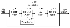
- FIG. 7 is a block diagram of the switch control unit 80.
- the switch control unit 80 is equipped with hardware as a general computer such as a CPU (Central Processing Unit), a RAM (Random Access Memory), a ROM (Read Only Memory), and an SSD (Solid State Drive). Stores an OS (Operating System), an application program, various data, and the like. The OS and application programs are expanded in RAM and executed by the CPU.
- a CPU Central Processing Unit
- RAM Random Access Memory
- ROM Read Only Memory
- SSD Solid State Drive
- the inside of the switch control unit 80 shows a function realized by an application program or the like as a block. That is, the switch control unit 80 includes a load information receiving unit 81, an allocated cell number calculation unit 82, a cell allocation unit 83, a control signal transmission unit 84, and a data table 85.
- the load information receiving unit 81 receives load information such as load power PL from each load device 30.
- the data table 85 stores information for specifying the pattern of the load power PL assumed for each DC bus 60 and the number of converter cells corresponding to each pattern.
- the allocated cell number calculation unit 82 calculates the number of converter cells to be allocated to each DC bus 60 (or each load device 30) according to the received load information and the contents of the data table 85. For example, the allocated cell number calculation unit 82 may search the data table 85 for the pattern closest to the pattern in the input load information, and calculate the number of converter cells based on the search result.
- the load power PL pattern stored in the data table 85 will be described.
- the load power PL of each load device 30 is 7 times the cell rated power PC.
- the data table 85 stores a value of 7 as the number of converter cells to be allocated to each DC bus 60 as data.
- the data table 85 also includes, as data, the number of converter cells to be allocated to each DC bus 103 for various patterns of load power of each DC bus 103.
- the data table 85 does not necessarily have to be provided, and the number obtained by dividing the load power PL by the cell rated power PC and rounding up to the nearest whole number may be used as the number of converter cells of the load device 30.
- the cell allocation unit 83 allocates converter cells 40 and 50 to each DC bus 60 based on the calculated number of converter cells.
- the control signal transmission unit 84 transmits a switch control signal for setting the on / off state of the switches 44 and 54 to the switch groups 44G and 54G so as to realize the allocation determined by the cell allocation unit 83.
- FIG. 8 is a flowchart of the cell allocation processing routine executed by the switch control unit 80.
- the load information receiving unit 81 receives load information such as each load power PL from the load device 30 connected to each DC bus 60.
- the allocation cell number calculation unit 82 calculates the number of converter cells connected to each DC bus 60.
- step S6 the cell allocation unit 83 selects one DC bus 60 to which the load device 30 is connected and to which the converter cells 40 and 50 have not yet been assigned. ..
- step S8 the cell allocation unit 83 calculates the “quotient” and the “remainder” when the number of converter cells is divided by “3”.
- the cell allocation unit 83 as the converter cell 40 connected to the selected DC bus 60, has the number of stages equal to the “quotient” (that is, the quotient” from the converter cell group 40G. Select the converter cells 40 (the number equal to 3 times). Further, in step S10, the cell allocation unit 83 selects a number of converter cells 50 equal to the “remainder” from the converter cell group 50G as the converter cells 50 connected to the selected DC bus 60.
- step S12 the cell allocation unit 83 determines whether or not the selection of the converter cells 40 and 50 has been completed in all the DC buses 60 to which the load device 30 is connected. If "No" is determined here, the process returns to step S6, and the processes of steps S6 to S10 are repeated for the other DC buses 60 to which the converter cells 40 and 50 have not been assigned yet.
- step S14 the cell allocation unit 83 includes the number of common cells JA, which is the number of stages of the converter cells 40 assigned to any DC bus 60, and any DC bus.
- the number of independent cells used KA which is the number of stages of the converter cells 50 assigned to 60, is specified.
- step S14 the control signal transmission unit 84 transmits the switch control signal that realizes the allocation determined by the cell allocation unit 83 to the switch groups 44G and 54G. This completes the processing of this routine.
- the converter cells 40 and 50 supply DC power to the corresponding load device 30 via the corresponding DC bus 60 according to the allocation determined by the cell allocation unit 83.
- Comparative example # 1 First, as a comparative example # 1, an example in which the common system stage number J shown in FIG. 1 is “0” will be examined. That is, in this comparative example # 1, the number of independent stages K is equal to the total number of stages N. Similar to the above-mentioned specific example, it is assumed that the number of DC buses used MA (number of load devices 30) is 3, and the load power PL is 7 times that of the cell rated power PC.
- a device such as a converter cell 40 has the highest efficiency when the output power is a cell rated power PC, and the efficiency decreases as the output power becomes lower than the cell rated power PC.
- the efficiency of the power conversion device 100 as a whole is lowered.
- the three input lines 22U, 22V, 22W to which the three-phase voltage is input and the respective input terminal INs are the respective input lines.
- Each output terminal OUT of 50 is provided with a plurality of switches 44, 54 for setting the connection state of each DC bus 60 of the M system, and each input line 22U, 22V, 22W and a neutral line 24 are provided.
- converter cells 40, 50 of the number of stages K (however, K NJ) connected to the common system line 42 together with the terminal OUT and connected between the respective input lines 22U, 22V, 22W and the neutral line 24.
- the output terminal OUT of one independent converter cell 50 is connected to an independent line 52 independent of the other two-phase independent converter cell 50, and the plurality of switches 44 and 54 are connected to each common line 42 and each.
- the electric power input from the three-phase power supply system 10 can be stably supplied to a plurality of load devices and the like, and can be realized by a small-scale circuit.
- the converter cell 40, 50 when each input terminal IN is connected in series between each input line 22U, 22V, 22W and the neutral line 24 by the number of stages N, the converter cell 40, 50 is further connected. preferable. As a result, the voltage input to the individual converter cells 40 and 50 can be reduced, and the configuration of the converter cells 40 and 50 can be simplified.
- the electric device information (PL) related to the electric device (30) connected to a part or all of the DC bus 60 of the M system is acquired, and the switches 44 and 54 are connected based on the acquired electric device information (PL). It is more preferable to further include a switch control unit 80 for setting a state. As a result, the states of the switches 44 and 54 can be automatically set based on the electrical equipment information (PL).
- the switch control unit 80 further includes an allocation cell number calculation unit 82 that calculates the number of converter cells 40, 50 connected to each DC bus 60 based on the electrical equipment information (PL). Thereby, the number of converter cells 40 and 50 connected to the direct current bus 60 can be automatically obtained based on the electric device information (PL).
- the allocation cell number calculation unit 82 determines the number of common system cells JA used, which is the number of common system converter cells (40) for supplying power to any DC bus 60, from a number of 3 ⁇ J or less. It is more preferable to have a function and a function of determining the number of independent cells used KA, which is the number of independent converter cells 50 for supplying power to any DC bus 60, from a number of 3 ⁇ K or less. As a result, the number of common cells used JA and the number of independent cells used KA can be automatically determined.
- the converter cells 40 and 50 are connected to the high frequency transformer 74, the first power converter (71, 73) connected to the primary side of the high frequency transformer 74, and the second power converter (71, 73) connected to the secondary side of the high frequency transformer 74. It is more preferable to include the power converter (75) of the above. As a result, electric power can be efficiently converted while insulating the primary side and the secondary side.
- the converter cells 40 and 50 further include a first capacitor (77) connected in series between the first power converter (71, 73) and the high frequency transformer 74.
- the resonance circuit can be formed by the first capacitor (77) and the high frequency transformer 74, and the power is transmitted from the first power converter (71, 73) to the second power converter (75). Can be further improved.
- the converter cells 40 and 50 further include a second capacitor (78) connected in series between the second power converter (75) and the high frequency transformer 74.
- a resonance circuit can be formed by the first capacitor (77), the second capacitor (78), and the high frequency transformer 74, and the first power converter (71, 73) can convert the second power.
- the power transmission to the capacitor (75) can be further improved.
- the present invention is not limited to the above-described embodiment, and various modifications are possible.
- the above-described embodiments are exemplified for the purpose of explaining the present invention in an easy-to-understand manner, and are not necessarily limited to those having all the configurations described. Further, it is possible to replace a part of the configuration of one embodiment with the configuration of another embodiment, and it is also possible to add the configuration of another embodiment to the configuration of one embodiment. Further, it is possible to delete a part of the configuration of each embodiment, or add / replace another configuration.
- the control lines and information lines shown in the figure show what is considered necessary for explanation, and do not necessarily show all the control lines and information lines necessary for the product. In practice, it can be considered that almost all configurations are interconnected. Possible modifications to the above embodiment are, for example, as follows.
- the load device 30 is applied as an electric device connected to the DC bus 60
- the electric device connected to the DC bus 60 is not limited to the load device 30, and may be, for example, a power generation device such as solar power generation or wind power generation.
- these electric devices may supply load power or power to be generated to the switch control unit 80 as electric device information.
- the input terminal INs of the converter cells 40 and 50 are connected in series between the input lines 22U, 22V, 22W and the neutral line 24.
- the present invention is not limited to this, and the input terminal INs of the converter cells 40 and 50 may be connected in parallel between the input lines 22U, 22V, 22W and the neutral line 24.
- the method of connecting the input terminal INs of the plurality of converter cells 40 may be a combination of series and parallel.
- the data table 85 (see FIG. 7) in the second embodiment may be placed in a cloud or the like on a network (not shown), or may not be included in the switch control unit 80.
Landscapes
- Engineering & Computer Science (AREA)
- Power Engineering (AREA)
- Transportation (AREA)
- Mechanical Engineering (AREA)
- Inverter Devices (AREA)
- Dc-Dc Converters (AREA)
- Supply And Distribution Of Alternating Current (AREA)
Abstract
Description
この発明は上述した事情に鑑みてなされたものであり、三相電源系統から入力された交流電力を安定的に直流電力に変換でき、かつ、小規模な回路で実現できる電力変換装置を提供することを目的とする。
〈第1実施形態の構成〉
図1は、好適な第1実施形態による電力変換装置100の前段部100Fのブロック図である。
図1において、電力変換装置100は、三相交流リアクトル20と、U相,V相,W相の入力線路22U,22V,22Wと、を介して三相電源系統10に接続されている。電力変換装置100の内部には、中性線24が設けられており、入力線路22Uと中性線24との間には、J段のコンバータセル40U-1~40U-Jの入力端子INと、K段のコンバータセル50U-1~50U-Kの入力端子INと、が順次直列に接続されている。ここで、JおよびKは自然数である。
図2において、共通系線路群42Gおよび独立系線路群52Gは、図1において説明した通りである。また、電力変換装置100には、正負一対のM系統の直流バス60-1~60-Mが設けられている。これら個々の直流バスを「直流バス60」と呼ぶことがある。また、Mを「直流バス数」と呼ぶことがある。
図3は、コンバータセル70Aのブロック図である。ここで、コンバータセル70Aは、上述したコンバータセル40,50として適用可能な装置の一例である。
図3において、コンバータセル70Aは、単相AC/DC変換器71(第1の電力変換器)と、平滑コンデンサ72と、単相DC/AC変換器73(第1の電力変換器)と、高周波トランス74と、単相AC/DC変換器75(第2の電力変換器)と、平滑コンデンサ76と、を備えている。
図4において、コンバータセル70Bは、コンバータセル70A(図3参照)と同様に構成されているが、単相DC/AC変換器73と高周波トランス74との間にコンデンサ77(第1のコンデンサ)が直列に挿入されている点が異なる。コンデンサ77を挿入したことにより、高周波トランス74とコンデンサ77とが共振回路を構成し、単相DC/AC変換器73から単相AC/DC変換器75への電力伝送を一層効率化することができる。
図5において、コンバータセル70Cは、コンバータセル70B(図4参照)と同様に構成されているが、高周波トランス74と単相AC/DC変換器75との間に、さらにコンデンサ78(第2のコンデンサ)が直列に挿入されている点が異なる。このように、高周波トランス74の1次側および2次側にコンデンサ77,78を挿入することによっても、高周波トランス74とコンデンサ77,78とが共振回路を構成し、単相DC/AC変換器73から単相AC/DC変換器75への電力伝送を一層効率化することができる。
図1に示したコンバータセル40,50は、必ずしも全てがオン状態にされるわけではなく、実際に接続される負荷装置30の種類や数に応じて、必要な数のコンバータセル40,50がオン状態にされ、他のコンバータセル40,50はオフ状態にされる。ここで、「オン状態」とは、出力端子OUTから何れかの直流バス60(図2参照)に直流電力を供給する状態のことであり、「オフ状態」とは、何れの直流バス60にも直流電力を供給しない状態のことである。
次に、好適な第2実施形態について説明する。なお、以下の説明において、上述した第1実施形態の各部に対応する部分には同一の符号を付し、その説明を省略する場合がある。
図6は、好適な第2実施形態による電力変換装置120の後段部120Rのブロック図である。なお、電力変換装置100の前段部の構成は、第1実施形態における前段部100F(図1参照)の構成と同一である。
スイッチ制御部80は、CPU(Central Processing Unit)、RAM(Random Access Memory)、ROM(Read Only Memory)、SSD(Solid State Drive)等、一般的なコンピュータとしてのハードウエアを備えており、SSDには、OS(Operating System)、アプリケーションプログラム、各種データ等が格納されている。OSおよびアプリケーションプログラムは、RAMに展開され、CPUによって実行される。
次に、本実施形態の動作を説明する。
図8は、スイッチ制御部80において実行されるセル割当処理ルーチンのフローチャートである。
図8において処理がステップS2に進むと、負荷情報受信部81は、各直流バス60に接続されている負荷装置30から、各々の負荷電力PL等の負荷情報を受信する。次に、処理がステップS4に進むと、割当セル数演算部82は、各直流バス60に接続するコンバータセル数を算出する。
次に、好適な実施形態の効果を明確化するため、比較例について説明する。
(比較例#1)
まず、比較例#1として、図1に示した共通系段数Jが「0」である例を検討する。すなわち、この比較例#1では、独立系段数Kが総段数Nに等しくなる。
上述した具体例と同様に、使用直流バス数MA(負荷装置30の数)が3であり、負荷電力PLがセル定格電力PCの7倍であったとする。本比較例#1においては、各負荷装置30に対して、コンバータセル50が各7台割り当てられ、使用されるコンバータセル50の合計台数は、7×3=21になり、上述した実施形態と同数である。
しかし、比較例#1では、電力変換装置100に設けるべきスイッチ54の数が膨大になるため、電力変換装置100が大型化し、高価になるという問題が生じる。
次に、比較例#2として、図1に示した独立系段数Kが「0」である例を検討する。すなわち、この比較例#2では、共通系段数Jが総段数Nに等しくなる。
上述した具体例と同様に、使用直流バス数MA(負荷装置30の数)が3であり、負荷電力PLがセル定格電力PCの7倍であったとする。本比較例#2においては、各負荷装置30に割り当て可能なコンバータセル40の数は、「3」の倍数になる。そして、PL/PC=7以上になる「3」の倍数は「9」であるため、使用されるコンバータセル40の合計台数は、9×3=27になり、コンバータセル40を有効利用できなくなる。
以上のように好適な実施形態によれば、電力変換装置100,120は、三相電圧が入力される三本の入力線路22U,22V,22Wと、各々の入力端子INが、各々の入力線路22U,22V,22Wと中性線24との間に直列または並列接続された、3×N個のコンバータセル40,50と、M系統の直流バス60と、3×N個のコンバータセル40,50の各々の出力端子OUTと、M系統の各々の直流バス60との接続状態を設定する複数のスイッチ44,54と、を備え、各々の入力線路22U,22V,22Wと中性線24との間に接続された段数J(但し、N>J)のコンバータセル40,50である共通系コンバータセル(40)の出力端子OUTは、他の二相の共通系コンバータセル(40)の出力端子OUTとともに共通系線路42に接続され、各々の入力線路22U,22V,22Wと中性線24との間に接続された段数K(但し、K=N-J)のコンバータセル40,50である独立系コンバータセル50の出力端子OUTは、他の二相の独立系コンバータセル50とは独立した独立系線路52に接続され、複数のスイッチ44,54は、各々の共通系線路42と各々の直流バス60との接続関係を切り替える共通系スイッチ(44)と、各々の独立系線路52と各々の直流バス60との接続関係を切り替える独立系スイッチ(54)と、を有する。これにより、三相電源系統10から入力された電力を複数の負荷装置等に安定的に供給でき、かつ、小規模な回路で実現できる。
本発明は上述した実施形態に限定されるものではなく、種々の変形が可能である。上述した実施形態は本発明を理解しやすく説明するために例示したものであり、必ずしも説明した全ての構成を備えるものに限定されるものではない。また、ある実施形態の構成の一部を他の実施形態の構成に置き換えることが可能であり、ある実施形態の構成に他の実施形態の構成を加えることも可能である。また、各実施形態の構成の一部について削除し、もしくは他の構成の追加・置換をすることが可能である。また、図中に示した制御線や情報線は説明上必要と考えられるものを示しており、製品上で必要な全ての制御線や情報線を示しているとは限らない。実際には殆ど全ての構成が相互に接続されていると考えてもよい。上記実施形態に対して可能な変形は、例えば以下のようなものである。
24 中性線
30 負荷装置(電気機器)
40 コンバータセル(共通系コンバータセル)
42 共通系線路
44 スイッチ(共通系スイッチ)
50 コンバータセル(独立系コンバータセル)
52 独立系線路
54 スイッチ(独立系スイッチ)
60 直流バス
71 単相AC/DC変換器(第1の電力変換器)
73 単相DC/AC変換器(第1の電力変換器)
74 高周波トランス
75 単相AC/DC変換器(第2の電力変換器)
77 コンデンサ(第1のコンデンサ)
78 コンデンサ(第2のコンデンサ)
80 スイッチ制御部
82 割当セル数演算部
100,120 電力変換装置
IN 入力端子
JA 使用共通系セル数
KA 使用独立系セル数
PL 負荷電力(電気機器情報)
OUT 出力端子
Claims (8)
- 三相電圧が入力される三本の入力線路と、
各々の入力端子が、各々の前記入力線路と中性線との間に直列または並列接続された、3×N個のコンバータセルと、
M系統の直流バスと、
3×N個の前記コンバータセルの各々の出力端子と、M系統の各々の前記直流バスとの接続状態を設定する複数のスイッチと、を備え、
各々の前記入力線路と前記中性線との間に接続された段数J(但し、N>J)の前記コンバータセルである共通系コンバータセルの前記出力端子は、他の二相の前記共通系コンバータセルの前記出力端子とともに共通系線路に接続され、
各々の前記入力線路と前記中性線との間に接続された段数K(但し、K=N-J)の前記コンバータセルである独立系コンバータセルの前記出力端子は、他の二相の前記独立系コンバータセルとは独立した独立系線路に接続され、
複数の前記スイッチは、各々の前記共通系線路と各々の前記直流バスとの接続関係を切り替える共通系スイッチと、各々の前記独立系線路と各々の前記直流バスとの接続関係を切り替える独立系スイッチと、を有する
ことを特徴とする電力変換装置。 - 3×N個の前記コンバータセルは、各々の前記入力端子が、各々の前記入力線路と前記中性線との間に段数Nずつ直列に接続されている
ことを特徴とする請求項1に記載の電力変換装置。 - M系統の前記直流バスの一部または全部に接続された電気機器に関する電気機器情報を取得し、取得した前記電気機器情報に基づいて前記スイッチの接続状態を設定するスイッチ制御部をさらに備える
ことを特徴とする請求項2に記載の電力変換装置。 - 前記スイッチ制御部は、
前記電気機器情報に基づいて、各々の前記直流バスに接続する前記コンバータセルの数を演算する割当セル数演算部をさらに備える
ことを特徴とする請求項3に記載の電力変換装置。 - 前記割当セル数演算部は、
何れかの前記直流バスに電力を供給する前記共通系コンバータセルの数である使用共通系セル数を3×J以下の数の中から決定する機能と、
何れかの前記直流バスに電力を供給する前記独立系コンバータセルの数である使用独立系セル数を3×K以下の数の中から決定する機能と、を備える
ことを特徴とする請求項4に記載の電力変換装置。 - 前記コンバータセルは、
高周波トランスと、
前記高周波トランスの一次側に接続された第1の電力変換器と、
前記高周波トランスの二次側に接続された第2の電力変換器と、を備える
ことを特徴とする請求項1ないし5の何れか一項に記載の電力変換装置。 - 前記コンバータセルは、前記第1の電力変換器と、前記高周波トランスとの間に直列接続された第1のコンデンサをさらに備える
ことを特徴とする請求項6に記載の電力変換装置。 - 前記コンバータセルは、前記第2の電力変換器と、前記高周波トランスとの間に直列接続された第2のコンデンサをさらに備える
ことを特徴とする請求項7に記載の電力変換装置。
Priority Applications (3)
| Application Number | Priority Date | Filing Date | Title |
|---|---|---|---|
| US18/021,644 US12249828B2 (en) | 2020-08-24 | 2021-05-07 | Power conversion device |
| EP21860863.6A EP4203285A4 (en) | 2020-08-24 | 2021-05-07 | POWER CONVERSION DEVICE |
| JP2022545305A JP7462056B2 (ja) | 2020-08-24 | 2021-05-07 | 電力変換装置 |
Applications Claiming Priority (2)
| Application Number | Priority Date | Filing Date | Title |
|---|---|---|---|
| JP2020140731 | 2020-08-24 | ||
| JP2020-140731 | 2020-08-24 |
Publications (1)
| Publication Number | Publication Date |
|---|---|
| WO2022044431A1 true WO2022044431A1 (ja) | 2022-03-03 |
Family
ID=80352999
Family Applications (1)
| Application Number | Title | Priority Date | Filing Date |
|---|---|---|---|
| PCT/JP2021/017476 Ceased WO2022044431A1 (ja) | 2020-08-24 | 2021-05-07 | 電力変換装置 |
Country Status (4)
| Country | Link |
|---|---|
| US (1) | US12249828B2 (ja) |
| EP (1) | EP4203285A4 (ja) |
| JP (1) | JP7462056B2 (ja) |
| WO (1) | WO2022044431A1 (ja) |
Cited By (2)
| Publication number | Priority date | Publication date | Assignee | Title |
|---|---|---|---|---|
| EP4369564A1 (en) * | 2022-11-09 | 2024-05-15 | Hitachi, Ltd. | Power conversion device and charging station |
| US12620913B2 (en) | 2022-11-09 | 2026-05-05 | Hitachi, Ltd. | Power conversion device including a plurality of converter units and a bidirectional DC/DC converter connected between two dc outputs of a plurality of dc outputs of the plurality of converter units |
Families Citing this family (2)
| Publication number | Priority date | Publication date | Assignee | Title |
|---|---|---|---|---|
| FR3095992B1 (fr) * | 2019-05-14 | 2022-01-21 | Hadi Moussavi | Systeme et procede de charge en energie electrique de vehicules automobiles |
| JP2022185478A (ja) * | 2021-06-02 | 2022-12-14 | 株式会社日立製作所 | 電力変換装置、電力変換システム、および、電力変換装置の制御方法 |
Citations (5)
| Publication number | Priority date | Publication date | Assignee | Title |
|---|---|---|---|---|
| JPH10271823A (ja) * | 1997-03-21 | 1998-10-09 | Shindengen Electric Mfg Co Ltd | 3相力率改善型コンバータ |
| JPH11113256A (ja) * | 1997-10-03 | 1999-04-23 | Shindengen Electric Mfg Co Ltd | 3相力率改善形コンバータ |
| WO2014132321A1 (ja) * | 2013-02-26 | 2014-09-04 | 株式会社 日立製作所 | 電源装置 |
| US9590483B1 (en) * | 2015-10-15 | 2017-03-07 | Ge Energy Power Conversion Technology Ltd | Control of balance of arm capacitor voltages in STATCOMS based on chain links of H bridge modules |
| JP2019213424A (ja) * | 2018-06-08 | 2019-12-12 | 株式会社日立製作所 | 充電装置 |
Family Cites Families (11)
| Publication number | Priority date | Publication date | Assignee | Title |
|---|---|---|---|---|
| JP2012070479A (ja) | 2010-09-21 | 2012-04-05 | Ntt Facilities Inc | 充電電力供給システム |
| US20150070939A1 (en) * | 2013-09-06 | 2015-03-12 | General Electric Company | Electric power conversion system and method of operating the same |
| DE102016123924A1 (de) * | 2016-12-09 | 2018-06-14 | Dr. Ing. H.C. F. Porsche Aktiengesellschaft | Modulare Leistungselektronik zum Laden eines elektrisch betriebenen Fahrzeugs |
| DE102016125720A1 (de) | 2016-12-27 | 2018-06-28 | Universität der Bundeswehr München | Niedervoltauskopplung aus einem modularen Energiespeicher-Umrichtersystem |
| WO2018126393A1 (en) * | 2017-01-05 | 2018-07-12 | General Electric Company | Dc fast charging station for electric vehicles |
| CN108574420B (zh) * | 2017-03-08 | 2020-02-28 | 台达电子企业管理(上海)有限公司 | 电力电子变换单元及系统 |
| CN107276125B (zh) * | 2017-07-06 | 2023-06-27 | 南京南瑞继保电气有限公司 | 一种链式多端口并网接口装置及控制方法 |
| DE102017116887A1 (de) * | 2017-07-26 | 2019-01-31 | Wobben Properties Gmbh | Ladestation mit dynamischer Ladestromverteilung |
| CN110677060B (zh) * | 2018-07-02 | 2021-08-03 | 台达电子工业股份有限公司 | 功率变换系统及其中直流母线电容的预充电方法 |
| CN112217406A (zh) * | 2019-07-11 | 2021-01-12 | 台达电子工业股份有限公司 | 应用于固态变压器架构的电源装置及三相电源系统 |
| CN112350588B (zh) * | 2019-08-07 | 2023-07-25 | 台达电子工业股份有限公司 | 应用于固态变压器架构的电源装置及三相电源系统 |
-
2021
- 2021-05-07 US US18/021,644 patent/US12249828B2/en active Active
- 2021-05-07 JP JP2022545305A patent/JP7462056B2/ja active Active
- 2021-05-07 EP EP21860863.6A patent/EP4203285A4/en active Pending
- 2021-05-07 WO PCT/JP2021/017476 patent/WO2022044431A1/ja not_active Ceased
Patent Citations (5)
| Publication number | Priority date | Publication date | Assignee | Title |
|---|---|---|---|---|
| JPH10271823A (ja) * | 1997-03-21 | 1998-10-09 | Shindengen Electric Mfg Co Ltd | 3相力率改善型コンバータ |
| JPH11113256A (ja) * | 1997-10-03 | 1999-04-23 | Shindengen Electric Mfg Co Ltd | 3相力率改善形コンバータ |
| WO2014132321A1 (ja) * | 2013-02-26 | 2014-09-04 | 株式会社 日立製作所 | 電源装置 |
| US9590483B1 (en) * | 2015-10-15 | 2017-03-07 | Ge Energy Power Conversion Technology Ltd | Control of balance of arm capacitor voltages in STATCOMS based on chain links of H bridge modules |
| JP2019213424A (ja) * | 2018-06-08 | 2019-12-12 | 株式会社日立製作所 | 充電装置 |
Non-Patent Citations (1)
| Title |
|---|
| See also references of EP4203285A4 * |
Cited By (2)
| Publication number | Priority date | Publication date | Assignee | Title |
|---|---|---|---|---|
| EP4369564A1 (en) * | 2022-11-09 | 2024-05-15 | Hitachi, Ltd. | Power conversion device and charging station |
| US12620913B2 (en) | 2022-11-09 | 2026-05-05 | Hitachi, Ltd. | Power conversion device including a plurality of converter units and a bidirectional DC/DC converter connected between two dc outputs of a plurality of dc outputs of the plurality of converter units |
Also Published As
| Publication number | Publication date |
|---|---|
| JPWO2022044431A1 (ja) | 2022-03-03 |
| JP7462056B2 (ja) | 2024-04-04 |
| EP4203285A1 (en) | 2023-06-28 |
| US20240039414A1 (en) | 2024-02-01 |
| EP4203285A4 (en) | 2024-08-28 |
| US12249828B2 (en) | 2025-03-11 |
Similar Documents
| Publication | Publication Date | Title |
|---|---|---|
| JP4898899B2 (ja) | 電力変換装置 | |
| CN101262178B (zh) | 采用级联结构的多电平逆变器及其控制方法 | |
| EP3059847B1 (en) | Power conversion device and power conversion method | |
| KR102824180B1 (ko) | 전력 그리드 | |
| JP7462056B2 (ja) | 電力変換装置 | |
| US9520801B1 (en) | Method and system for a gas tube switch-based voltage source high voltage direct current transmission system | |
| US9748857B2 (en) | Method and system for a gas tube-based current source high voltage direct current transmission system | |
| KR20170004345A (ko) | 모듈형 멀티 레벨 컨버터 및 모듈형 멀티 레벨 컨버터의 전압 밸런싱 제어 방법 | |
| US10886858B1 (en) | Modular multi-level converter pre-chargers | |
| US12542497B2 (en) | Power conversion device, power conversion system, and method for controlling power conversion device | |
| EP4325709A1 (en) | Alternating current/direct current power conversion system | |
| JP2017184607A (ja) | 配電システム及び電力合成回路 | |
| Kabalcı | Solid state transformers with multilevel inverters | |
| US20180166983A1 (en) | Column-Switched Multi-Module DC-to-DC Power Transformation System | |
| CN218071329U (zh) | 一种基于移相变压器的直流供电系统 | |
| US20250149909A1 (en) | Charging system and charging system control device | |
| JP7641856B2 (ja) | 充電装置 | |
| KR20210044538A (ko) | 커패시터 구동을 이용하는 고배율 dc-dc 컨버터 | |
| JP7230633B2 (ja) | 電力変換装置 | |
| KR20160072499A (ko) | 모듈형 멀티 레벨 컨버터의 운전 방법 | |
| CN120749857B (zh) | 基于级联h桥的电池储能系统、方法、控制器及介质 | |
| US12620913B2 (en) | Power conversion device including a plurality of converter units and a bidirectional DC/DC converter connected between two dc outputs of a plurality of dc outputs of the plurality of converter units | |
| EP4734349A1 (en) | Converter system for connecting first ac system to second ac system and method thereof | |
| JP2008104253A (ja) | 電力変換装置 | |
| US20240154542A1 (en) | Power conversion device |
Legal Events
| Date | Code | Title | Description |
|---|---|---|---|
| 121 | Ep: the epo has been informed by wipo that ep was designated in this application |
Ref document number: 21860863 Country of ref document: EP Kind code of ref document: A1 |
|
| ENP | Entry into the national phase |
Ref document number: 2022545305 Country of ref document: JP Kind code of ref document: A |
|
| WWE | Wipo information: entry into national phase |
Ref document number: 18021644 Country of ref document: US |
|
| NENP | Non-entry into the national phase |
Ref country code: DE |
|
| ENP | Entry into the national phase |
Ref document number: 2021860863 Country of ref document: EP Effective date: 20230324 |
|
| WWG | Wipo information: grant in national office |
Ref document number: 18021644 Country of ref document: US |