WO2022049761A1 - 音声信号処理装置、音声信号処理方法およびプログラム - Google Patents
音声信号処理装置、音声信号処理方法およびプログラム Download PDFInfo
- Publication number
- WO2022049761A1 WO2022049761A1 PCT/JP2020/033744 JP2020033744W WO2022049761A1 WO 2022049761 A1 WO2022049761 A1 WO 2022049761A1 JP 2020033744 W JP2020033744 W JP 2020033744W WO 2022049761 A1 WO2022049761 A1 WO 2022049761A1
- Authority
- WO
- WIPO (PCT)
- Prior art keywords
- audio signal
- buffer
- signal processing
- processing device
- feedback path
- Prior art date
- Legal status (The legal status is an assumption and is not a legal conclusion. Google has not performed a legal analysis and makes no representation as to the accuracy of the status listed.)
- Ceased
Links
Images

Classifications
-
- G—PHYSICS
- G06—COMPUTING OR CALCULATING; COUNTING
- G06F—ELECTRIC DIGITAL DATA PROCESSING
- G06F3/00—Input arrangements for transferring data to be processed into a form capable of being handled by the computer; Output arrangements for transferring data from processing unit to output unit, e.g. interface arrangements
- G06F3/16—Sound input; Sound output
- G06F3/162—Interface to dedicated audio devices, e.g. audio drivers, interface to CODECs
-
- H—ELECTRICITY
- H03—ELECTRONIC CIRCUITRY
- H03G—CONTROL OF AMPLIFICATION
- H03G3/00—Gain control in amplifiers or frequency changers
- H03G3/20—Automatic control
- H03G3/30—Automatic control in amplifiers having semiconductor devices
- H03G3/3005—Automatic control in amplifiers having semiconductor devices in amplifiers suitable for low-frequencies, e.g. audio amplifiers
- H03G3/301—Automatic control in amplifiers having semiconductor devices in amplifiers suitable for low-frequencies, e.g. audio amplifiers the gain being continuously variable
-
- G—PHYSICS
- G10—MUSICAL INSTRUMENTS; ACOUSTICS
- G10H—ELECTROPHONIC MUSICAL INSTRUMENTS; INSTRUMENTS IN WHICH THE TONES ARE GENERATED BY ELECTROMECHANICAL MEANS OR ELECTRONIC GENERATORS, OR IN WHICH THE TONES ARE SYNTHESISED FROM A DATA STORE
- G10H1/00—Details of electrophonic musical instruments
- G10H1/0091—Means for obtaining special acoustic effects
-
- G—PHYSICS
- G10—MUSICAL INSTRUMENTS; ACOUSTICS
- G10H—ELECTROPHONIC MUSICAL INSTRUMENTS; INSTRUMENTS IN WHICH THE TONES ARE GENERATED BY ELECTROMECHANICAL MEANS OR ELECTRONIC GENERATORS, OR IN WHICH THE TONES ARE SYNTHESISED FROM A DATA STORE
- G10H1/00—Details of electrophonic musical instruments
- G10H1/36—Accompaniment arrangements
- G10H1/40—Rhythm
-
- G—PHYSICS
- G10—MUSICAL INSTRUMENTS; ACOUSTICS
- G10H—ELECTROPHONIC MUSICAL INSTRUMENTS; INSTRUMENTS IN WHICH THE TONES ARE GENERATED BY ELECTROMECHANICAL MEANS OR ELECTRONIC GENERATORS, OR IN WHICH THE TONES ARE SYNTHESISED FROM A DATA STORE
- G10H2210/00—Aspects or methods of musical processing having intrinsic musical character, i.e. involving musical theory or musical parameters or relying on musical knowledge, as applied in electrophonic musical tools or instruments
- G10H2210/101—Music Composition or musical creation; Tools or processes therefor
- G10H2210/125—Medley, i.e. linking parts of different musical pieces in one single piece, e.g. sound collage, DJ mix
-
- G—PHYSICS
- G10—MUSICAL INSTRUMENTS; ACOUSTICS
- G10H—ELECTROPHONIC MUSICAL INSTRUMENTS; INSTRUMENTS IN WHICH THE TONES ARE GENERATED BY ELECTROMECHANICAL MEANS OR ELECTRONIC GENERATORS, OR IN WHICH THE TONES ARE SYNTHESISED FROM A DATA STORE
- G10H2210/00—Aspects or methods of musical processing having intrinsic musical character, i.e. involving musical theory or musical parameters or relying on musical knowledge, as applied in electrophonic musical tools or instruments
- G10H2210/155—Musical effects
- G10H2210/195—Modulation effects, i.e. smooth non-discontinuous variations over a time interval, e.g. within a note, melody or musical transition, of any sound parameter, e.g. amplitude, pitch, spectral response or playback speed
- G10H2210/235—Flanging or phasing effects, i.e. creating time and frequency dependent constructive and destructive interferences, obtained, e.g. by using swept comb filters or a feedback loop around all-pass filters with gradually changing non-linear phase response or delays
-
- G—PHYSICS
- G10—MUSICAL INSTRUMENTS; ACOUSTICS
- G10H—ELECTROPHONIC MUSICAL INSTRUMENTS; INSTRUMENTS IN WHICH THE TONES ARE GENERATED BY ELECTROMECHANICAL MEANS OR ELECTRONIC GENERATORS, OR IN WHICH THE TONES ARE SYNTHESISED FROM A DATA STORE
- G10H2210/00—Aspects or methods of musical processing having intrinsic musical character, i.e. involving musical theory or musical parameters or relying on musical knowledge, as applied in electrophonic musical tools or instruments
- G10H2210/155—Musical effects
- G10H2210/265—Acoustic effect simulation, i.e. volume, spatial, resonance or reverberation effects added to a musical sound, usually by appropriate filtering or delays
-
- G—PHYSICS
- G10—MUSICAL INSTRUMENTS; ACOUSTICS
- G10H—ELECTROPHONIC MUSICAL INSTRUMENTS; INSTRUMENTS IN WHICH THE TONES ARE GENERATED BY ELECTROMECHANICAL MEANS OR ELECTRONIC GENERATORS, OR IN WHICH THE TONES ARE SYNTHESISED FROM A DATA STORE
- G10H2210/00—Aspects or methods of musical processing having intrinsic musical character, i.e. involving musical theory or musical parameters or relying on musical knowledge, as applied in electrophonic musical tools or instruments
- G10H2210/375—Tempo or beat alterations; Music timing control
- G10H2210/385—Speed change, i.e. variations from preestablished tempo, tempo change, e.g. faster or slower, accelerando or ritardando, without change in pitch
-
- G—PHYSICS
- G10—MUSICAL INSTRUMENTS; ACOUSTICS
- G10H—ELECTROPHONIC MUSICAL INSTRUMENTS; INSTRUMENTS IN WHICH THE TONES ARE GENERATED BY ELECTROMECHANICAL MEANS OR ELECTRONIC GENERATORS, OR IN WHICH THE TONES ARE SYNTHESISED FROM A DATA STORE
- G10H2210/00—Aspects or methods of musical processing having intrinsic musical character, i.e. involving musical theory or musical parameters or relying on musical knowledge, as applied in electrophonic musical tools or instruments
- G10H2210/375—Tempo or beat alterations; Music timing control
- G10H2210/391—Automatic tempo adjustment, correction or control
-
- G—PHYSICS
- G10—MUSICAL INSTRUMENTS; ACOUSTICS
- G10H—ELECTROPHONIC MUSICAL INSTRUMENTS; INSTRUMENTS IN WHICH THE TONES ARE GENERATED BY ELECTROMECHANICAL MEANS OR ELECTRONIC GENERATORS, OR IN WHICH THE TONES ARE SYNTHESISED FROM A DATA STORE
- G10H2250/00—Aspects of algorithms or signal processing methods without intrinsic musical character, yet specifically adapted for or used in electrophonic musical processing
- G10H2250/041—Delay lines applied to musical processing
-
- G—PHYSICS
- G10—MUSICAL INSTRUMENTS; ACOUSTICS
- G10H—ELECTROPHONIC MUSICAL INSTRUMENTS; INSTRUMENTS IN WHICH THE TONES ARE GENERATED BY ELECTROMECHANICAL MEANS OR ELECTRONIC GENERATORS, OR IN WHICH THE TONES ARE SYNTHESISED FROM A DATA STORE
- G10H2250/00—Aspects of algorithms or signal processing methods without intrinsic musical character, yet specifically adapted for or used in electrophonic musical processing
- G10H2250/471—General musical sound synthesis principles, i.e. sound category-independent synthesis methods
- G10H2250/511—Physical modelling or real-time simulation of the acoustomechanical behaviour of acoustic musical instruments using, e.g. waveguides or looped delay lines
- G10H2250/521—Closed loop models therefor, e.g. with filter and delay line
-
- G—PHYSICS
- G10—MUSICAL INSTRUMENTS; ACOUSTICS
- G10H—ELECTROPHONIC MUSICAL INSTRUMENTS; INSTRUMENTS IN WHICH THE TONES ARE GENERATED BY ELECTROMECHANICAL MEANS OR ELECTRONIC GENERATORS, OR IN WHICH THE TONES ARE SYNTHESISED FROM A DATA STORE
- G10H2250/00—Aspects of algorithms or signal processing methods without intrinsic musical character, yet specifically adapted for or used in electrophonic musical processing
- G10H2250/541—Details of musical waveform synthesis, i.e. audio waveshape processing from individual wavetable samples, independently of their origin or of the sound they represent
- G10H2250/641—Waveform sampler, i.e. music samplers; Sampled music loop processing, wherein a loop is a sample of a performance that has been edited to repeat seamlessly without clicks or artifacts
-
- H—ELECTRICITY
- H04—ELECTRIC COMMUNICATION TECHNIQUE
- H04R—LOUDSPEAKERS, MICROPHONES, GRAMOPHONE PICK-UPS OR LIKE ACOUSTIC ELECTROMECHANICAL TRANSDUCERS; ELECTRIC HEARING AIDS; PUBLIC ADDRESS SYSTEMS
- H04R3/00—Circuits for transducers
-
- H—ELECTRICITY
- H04—ELECTRIC COMMUNICATION TECHNIQUE
- H04R—LOUDSPEAKERS, MICROPHONES, GRAMOPHONE PICK-UPS OR LIKE ACOUSTIC ELECTROMECHANICAL TRANSDUCERS; ELECTRIC HEARING AIDS; PUBLIC ADDRESS SYSTEMS
- H04R5/00—Stereophonic arrangements
Definitions
- the present invention relates to an audio signal processing device, an audio signal processing method and a program.
- Patent Document 1 Various technologies for improving functionality and operability have been proposed in audio equipment such as controllers and mixers used for DJ performance. Examples of such techniques are described, for example, in Patent Document 1, Patent Document 2, and Patent Document 3.
- an object of the present invention is to provide an audio signal processing device, an audio signal processing method, and a program capable of improving the effect added to a music by using a buffer.
- a voice signal processing device including a second buffer.
- the gate is turned on when a predetermined trigger operation is performed and is turned off when a predetermined time worth of audio signals are transmitted.
- the audio signal processing device according to any one of [1] to [3], wherein the delay time of the audio signal by the second buffer is equal to or less than the delay time of the audio signal by the first buffer.
- the audio signal processing device according to any one of [1] to [4], further comprising a variable amplifier or an attenuator connected in the feedback path.
- the second buffer includes a plurality of buffers connected in parallel.
- a voice signal processing method including a step of outputting a voice signal stored in a second buffer and feeding it back to a second buffer.
- a program for operating a computer as an audio signal processing device including a second buffer.
- the audio signal stored in the first buffer at that time is input to the feedback path including the second buffer, so that the audio of the music played before the trigger operation
- the signal can be played repeatedly as an effect sound.
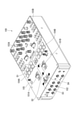
- FIG. 1 is a diagram showing an overall configuration of a mixer according to an embodiment of the present invention.
- the audio signal processing device is a mixer 100 used for DJ performance.
- the mixer 100 processes a two-channel audio signal input from an external sound source according to an operation on an operator such as a switch or a knob arranged in a housing, and outputs the signal to a speaker or the like.
- the controls of the mixer 100 include channel faders 101A and 101B, crossfaders 102, load buttons 103A and 103B, and performance pads 104A and 104B.
- the channel faders 101A and 101B are configured so that the volume of the music played in each channel can be gradually changed by sliding in the illustrated directions D1 and D2, and slides to the end of the range of motion in the direction D2. Then, the volume of each channel becomes 0.
- the crossfader 102 is configured to adjust the balance of the music played on each channel.
- the channel fader 101A side is the A channel and the channel fader 101B side is the B channel
- the crossfader 102 is slid to the end of the direction D3 shown
- the volume of the music of the B channel becomes 0 and is slid in the direction D4.
- the volume of the music on channel A becomes 0, and in the middle part, the music on both channels is played at a volume other than 0.
- the load buttons 103A and 103B are used to load the music played on each channel. Further, the performance pads 104A and 104B are used to execute a function such as a hot cue assigned by the user's setting for the music played on each channel.
- the controller of the mixer 100 includes a button 105 for activating the effect function described below. Since the controls of the mixer 100 including the faders and buttons described above are configured in the same manner as a normal mixer except that they are used for effect functions as described below, further details about the controls are given. The explanation is omitted.
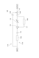
- FIG. 2 is a diagram showing the configuration of the effect circuit of the mixer shown in FIG.
- the audio signal processing circuit is implemented by software using a CPU (Central Processing Unit) or a DSP (Digital Signal Processor).
- the illustrated effect circuit 110 is connected to each of the A channel and the B channel of the mixer 100 after the volume adjustment process by the fader. Therefore, the audio signal input to the effect circuit 110 reflects the result of tone adjustment by the channel faders 101A and 101B and the crossfader 102. Specifically, for example, in a state where the channel faders 101A and 101B are slid to the end of the direction D2 shown in FIG.
- an audio signal (no signal) having a volume of 0 is input to each channel, and the crossfader 102 is used.
- an audio signal (no signal) having a volume of 0 is input in any of the channels.
- the effect circuit 110 includes transmission paths 111A and 111B connected in parallel.
- the transmission path 111A is a bypass path, and an audio signal of the original sound to which no effect is applied is transmitted.
- the transmission path 111B includes a circuit configuration for an effect as described later, and an audio signal of the effect sound is transmitted. The balance between the original sound and the effect sound is adjusted by the amplifiers 112A and 112B, and is added to each other by the adder 113 and output.
- a buffer 114A is connected to the transmission path 111B. The buffer 114A temporarily stores the input audio signal and then outputs the signal.
- a gate 115 is connected to the output side of the buffer 114A.
- a gate means a circuit element (implemented software as described above) configured to transmit a signal when it is on and to block the signal when it is off. do.
- the gate 115 is turned on when an effect trigger operation as described later is performed, and is turned off when an audio signal for a predetermined time is transmitted.
- the capacities of the buffers 114A and 114B connected to the effect circuit 110 may be variable. By adjusting the capacities of the buffers 114A and 114B, the delay time from the input of the audio signal to the buffers 114A and 114B to the output can be changed. In this case, the capacities of the buffers 114A and 114B may be automatically set so that the delay time is, for example, n times or 1 / n times (n is an integer) of the beat interval of the music being played. The delay time of the audio signal by the buffer 114B may be less than or equal to the delay time of the audio signal by the buffer 114A.
- the time length of the audio signal transmitted before the gate 115 is turned off may also be automatically set to be n times or 1 / n times the beat interval of the music being played, for example. Further, the timing at which the gate 115 is turned on / off may be automatically adjusted so as to match the beat interval of the music being played.
- a feedback path 117 having a start and an end is connected to the transmission path 111B on the output side of the buffer 114A, and the buffer 114B is connected in the feedback path 117.
- the feedback path 117 branches from the front of the amplifier 112B connected to the end of the transmission path 111B, and is connected to the adder 116 on the output side of the gate 115.
- the gate 115 is not included in the feedback path 117.
- the buffer 114B also temporarily stores the input audio signal and then outputs the signal. While the gate 115 is on, the audio signal stored in the buffer 114A is stored in the buffer 114B via the feedback path 117 in addition to being output as an effect sound through the adder 113.
- the audio signal stored in the buffer 114B is output as an effect sound via the adder 113, and is also stored in the buffer 114B again via the feedback path 117. As a result, the audio signal stored in the buffer 114B is repeatedly reproduced with a predetermined delay time.
- variable amplifier 118 or the attenuator is connected between the adder 116 and the branch point of the feedback path 117.
- the amplification factor is less than 1 in the variable amplifier 118 and when an attenuator is connected, the effect sound that is repeatedly reproduced is gradually attenuated (fade out).
- the amplification factor exceeds 1 in the variable amplifier 118, the effect sound is gradually amplified (fade in). If there is no variable amplifier 118 or the amplification factor is 1, the effect sound continues to be played repeatedly at the same volume (loop).
- FIG. 3 is a flowchart showing an example of processing in the effect circuit shown in FIG. For example, during the reproduction of a musical piece on each channel, the process described below is repeatedly executed. First, it is determined whether or not the effect function is turned on by pressing the button 105 shown in FIG. 1 (step S101). When the effect function is on (YES), the original sound is input to the buffer 1 (buffer 114A described above) (step S102). Next, it is determined whether or not the trigger operation has been performed (step S103).
- the trigger operation is, for example, the operation of setting the volume of each channel to 0 by the channel faders 101A and 101B and the crossfader 102, the operation of loading the music by the load buttons 103A and 103B, and the performance pads 104A and 104B as described above. It may include one or more of the hot cue operations used. Further, the gate cue, silent cue, and mute operations performed by controls such as the performance pads 104A and 104B or other buttons may be effect trigger operations.
- step S104 When the trigger operation is performed in the determination of step S103 above (YES), it is further determined whether or not the trigger operation is performed by the crossfader 102 (step S104).
- the trigger operation is performed by the crossfader 102 (YES)
- it is determined whether or not a predetermined invalid time has elapsed step S105.
- the invalid time is the elapsed time from the trigger operation by the previous crossfader 102, and the trigger operation by the next crossfader 102 executed before the invalid time elapses is invalidated. If the determination in step S104 is not a trigger operation by the crossfader 102 (NO), or if the invalid time has elapsed in the determination in step S105 (YES), the count is reset (S106).
- This count corresponds to the remaining time length of the audio signal transmitted after the gate 115 is turned on and before it is turned off.
- the effect function is not turned on, the trigger operation is not performed, or the invalid time has not elapsed in the determination of steps S101, S103, and S105 above, the count is not reset and the process is next. move on.
- the above-mentioned control based on the invalid time is effective, for example, when the crossfader 102 is operated in combination with a scratch.
- step S107 it is determined whether or not the count is larger than 0 (step S107).
- the count is decremented in a later step S110 for each cycle of the illustrated process, and will eventually become 0 unless it is reset. If the count is greater than 0 (YES), the gate 115 is on. In this case, the output of the buffer 1 (buffer 114A) and the output of the buffer 2 (buffer 114B) are added by the adder 116, and the voice signal multiplied by the amplification factor Z of the variable amplifier 118 is output via the adder 113. At the same time, it is fed back to the buffer 2 (buffer 114B) via the feedback path 117 (step S108).
- step S107 when the count is 0 in the determination of step S107 (NO), the gate 115 is off. In this case, the output of the buffer 1 (buffer 114A) is not input to the adder 116 side, but the output of the buffer 2 (buffer 114B) is amplified or attenuated by the variable amplifier 118 and then output via the adder 113. It is fed back to the buffer 2 (buffer 114B) via the feedback path 117 (step S109). After processing either step S108 or step S109 above, the count is decremented (step S110).
- the gate 115 is turned on by an effective trigger operation, and the output of the buffer 114A having a predetermined time length is input to the feedback path 117 including the buffer 114B.
- the gate 115 is turned off, and the audio signal output from the buffer 114A up to that point is a feedback path including the buffer 114B. It is repeatedly reproduced at 117.
- a variable amplifier 118 or an attenuator with an amplification factor Z less than 1 it is possible to add a type of effect called delay, echo, reverb, etc. to the music.
- the amplification factor Z of the variable amplifier 118 is set to 1 or more, or when the variable amplifier 118 is not connected, a kind of effect called a loop or the like can be added.
- the audio signal stored in the buffer 114A at that time is input to the feedback path 117 including the buffer 114B, so that the audio signal of the music played before the trigger operation is used as the effect sound. It can be played repeatedly. As a result, there is no need to separately perform an operation to turn on the effect at the start point of the section of the music to be played as the effect sound.
- the section of the music can be played repeatedly as an effect sound. Since the start point and end point of the section to be repeatedly reproduced are automatically determined by the capacities of the buffers 114A and 114B and the setting of the gate 115, it is not necessary to determine the end point of the section.
- the repetitive playback section is limited, a plurality of effect sounds can be superimposed with only one buffer 114B, and the processing load can be reduced.
- the buffer 114B may be set to a plurality of buffers connected in parallel, and the attenuation factor of the audio signal input to each buffer may be changed. ..
- a new audio signal is input to the feedback path 117 including the buffer 114B only while the gate 115 is on. Therefore, even if another song is played after the trigger operation, the sound of the song after the trigger operation can be prevented from overlapping with the effect sound. Specifically, even if the development of the music changes significantly due to, for example, a hot cue, effects such as echo can be added to the sound before the development changes, and the music can be connected without discomfort.
- the trigger operation is an operation to set the volume of each channel to 0, a new audio signal is not input to the buffer 114A after the trigger operation, so that the same processing can be performed without the gate 115.
- the audio signal processing device having the above functions is not limited to the mixer described as one embodiment, and may be, for example, a DJ controller having a mixer function.
- a DJ controller having a mixer function.
- a 2-channel mixer has been described, but a similar function can be realized with a 4-channel mixer, for example.
- the present invention is not limited to DJ equipment, and can be applied to audio equipment such as general mixers and electronic musical instruments.
- 100 ... Mixer, 101A, 101B ... Channel fader, 102 ... Crossfader, 103A, 103B ... Load button, 104A, 104B ... Performance pad, 105 ... Button, 110 ... Effect circuit, 111A, 111B ... Transmission path, 112A, 112B ... Amplifier, 113 ... adder, 114A, 114B ... buffer, 115 ... gate, 116 ... adder, 117 ... feedback path, 118 ... variable amplifier.
Landscapes
- Engineering & Computer Science (AREA)
- Multimedia (AREA)
- Theoretical Computer Science (AREA)
- Physics & Mathematics (AREA)
- General Health & Medical Sciences (AREA)
- Audiology, Speech & Language Pathology (AREA)
- Health & Medical Sciences (AREA)
- Human Computer Interaction (AREA)
- General Engineering & Computer Science (AREA)
- General Physics & Mathematics (AREA)
- Acoustics & Sound (AREA)
- Control Of Amplification And Gain Control (AREA)
- Amplifiers (AREA)
- Circuit For Audible Band Transducer (AREA)
Abstract
Description
[2]第1のバッファの出力側に接続され、フィードバック経路には含まれないゲートをさらに備える、[1]に記載の音声信号処理装置。
[3]ゲートは、所定のトリガー操作がされた場合にオンになり、所定の時間分の音声信号を伝送するとオフになる、[2]に記載の音声信号処理装置。
[4]第2のバッファによる音声信号の遅延時間は、第1のバッファによる音声信号の遅延時間以下である、[1]から[3]のいずれか1項に記載の音声信号処理装置。
[5]フィードバック経路内に接続される可変増幅器または減衰器をさらに備える、[1]から[4]のいずれか1項に記載の音声信号処理装置。
[6]第2のバッファは、並列接続される複数のバッファを含む、[1]から[5]のいずれか1項に記載の音声信号処理装置。
[7]入力された音声信号を第1のバッファに一時的に蓄積するステップと、第1のバッファに蓄積された音声信号を出力するとともに第2のバッファに一時的に蓄積するステップと、第2のバッファに蓄積された音声信号を出力するとともに第2のバッファにフィードバックするステップとを含む音声信号処理方法。
[8]第2のバッファにフィードバックされる音声信号を増幅または減衰させるステップをさらに含む、[7]に記載の音声信号処理方法。
[9]音声信号が一時的に蓄積される第1のバッファと、第1のバッファの出力側に始端および終端を有するフィードバック経路と、フィードバック経路内に接続され、音声信号が一時的に蓄積される第2のバッファとを備える音声信号処理装置としてコンピュータを機能させるためのプログラム。
Claims (9)
- 音声信号が一時的に蓄積される第1のバッファと、
前記第1のバッファの出力側に始端および終端を有するフィードバック経路と、
前記フィードバック経路内に接続され、前記音声信号が一時的に蓄積される第2のバッファと
を備える音声信号処理装置。 - 前記第1のバッファの出力側に接続され、前記フィードバック経路には含まれないゲートをさらに備える、請求項1に記載の音声信号処理装置。
- 前記ゲートは、所定のトリガー操作がされた場合にオンになり、所定の時間分の前記音声信号を伝送するとオフになる、請求項2に記載の音声信号処理装置。
- 前記第2のバッファによる前記音声信号の遅延時間は、前記第1のバッファによる前記音声信号の遅延時間以下である、請求項1から請求項3のいずれか1項に記載の音声信号処理装置。
- 前記フィードバック経路内に接続される可変増幅器または減衰器をさらに備える、請求項1から請求項4のいずれか1項に記載の音声信号処理装置。
- 前記第2のバッファは、並列接続される複数のバッファを含む、請求項1から請求項5のいずれか1項に記載の音声信号処理装置。
- 入力された音声信号を第1のバッファに一時的に蓄積するステップと、
前記第1のバッファに蓄積された音声信号を出力するとともに第2のバッファに一時的に蓄積するステップと、
前記第2のバッファに蓄積された音声信号を出力するとともに前記第2のバッファにフィードバックするステップと
を含む音声信号処理方法。 - 前記第2のバッファにフィードバックされる音声信号を増幅または減衰させるステップをさらに含む、請求項7に記載の音声信号処理方法。
- 音声信号が一時的に蓄積される第1のバッファと、
前記第1のバッファの出力側に始端および終端を有するフィードバック経路と、
前記フィードバック経路内に接続され、前記音声信号が一時的に蓄積される第2のバッファと
を備える音声信号処理装置としてコンピュータを機能させるためのプログラム。
Priority Applications (4)
| Application Number | Priority Date | Filing Date | Title |
|---|---|---|---|
| JP2022546849A JP7787816B2 (ja) | 2020-09-07 | 2020-09-07 | 音声信号処理装置、音声信号処理方法およびプログラム |
| EP20952495.8A EP4213501A4 (en) | 2020-09-07 | 2020-09-07 | AUDIO SIGNAL PROCESSING DEVICE, AUDIO SIGNAL PROCESSING METHOD AND PROGRAM |
| PCT/JP2020/033744 WO2022049761A1 (ja) | 2020-09-07 | 2020-09-07 | 音声信号処理装置、音声信号処理方法およびプログラム |
| US18/044,131 US12379892B2 (en) | 2020-09-07 | 2020-09-07 | Audio signal processing device, audio signal processing method, and program |
Applications Claiming Priority (1)
| Application Number | Priority Date | Filing Date | Title |
|---|---|---|---|
| PCT/JP2020/033744 WO2022049761A1 (ja) | 2020-09-07 | 2020-09-07 | 音声信号処理装置、音声信号処理方法およびプログラム |
Publications (1)
| Publication Number | Publication Date |
|---|---|
| WO2022049761A1 true WO2022049761A1 (ja) | 2022-03-10 |
Family
ID=80490835
Family Applications (1)
| Application Number | Title | Priority Date | Filing Date |
|---|---|---|---|
| PCT/JP2020/033744 Ceased WO2022049761A1 (ja) | 2020-09-07 | 2020-09-07 | 音声信号処理装置、音声信号処理方法およびプログラム |
Country Status (4)
| Country | Link |
|---|---|
| US (1) | US12379892B2 (ja) |
| EP (1) | EP4213501A4 (ja) |
| JP (1) | JP7787816B2 (ja) |
| WO (1) | WO2022049761A1 (ja) |
Families Citing this family (3)
| Publication number | Priority date | Publication date | Assignee | Title |
|---|---|---|---|---|
| JP1716147S (ja) * | 2021-10-27 | 2022-05-30 | デジタルオーディオプレーヤー用操作機 | |
| USD1051127S1 (en) * | 2021-10-27 | 2024-11-12 | Alphatheta Corporation | Controller for digital audio player |
| JP7896387B2 (ja) * | 2022-07-01 | 2026-07-29 | ヤマハ株式会社 | 音信号処理方法及び音信号処理装置 |
Citations (8)
| Publication number | Priority date | Publication date | Assignee | Title |
|---|---|---|---|---|
| JPS6432599U (ja) * | 1987-08-20 | 1989-03-01 | ||
| JPH086584A (ja) * | 1954-05-31 | 1996-01-12 | Internatl Business Mach Corp <Ibm> | リアルタイム・ディジタル音声残響システム |
| JPH09244640A (ja) * | 1996-03-14 | 1997-09-19 | Kawai Musical Instr Mfg Co Ltd | 楽音制御装置 |
| JP2004309725A (ja) * | 2003-04-04 | 2004-11-04 | Roland Corp | 効果装置 |
| JP2010500834A (ja) * | 2007-02-16 | 2010-01-07 | ボーズ・コーポレーション | キックゲート |
| WO2019234861A1 (ja) | 2018-06-06 | 2019-12-12 | Pioneer DJ株式会社 | 音量操作装置 |
| WO2019239486A1 (ja) | 2018-06-12 | 2019-12-19 | Pioneer DJ株式会社 | 音響装置およびプログラム |
| WO2019239538A1 (ja) | 2018-06-14 | 2019-12-19 | Pioneer DJ株式会社 | 音響装置およびプログラム |
Family Cites Families (8)
| Publication number | Priority date | Publication date | Assignee | Title |
|---|---|---|---|---|
| JPS5650560Y2 (ja) | 1975-05-20 | 1981-11-26 | ||
| JPS61169897A (ja) | 1985-01-23 | 1986-07-31 | ヤマハ株式会社 | 残響付加装置 |
| JPH04181992A (ja) | 1990-11-16 | 1992-06-29 | Yamaha Corp | テンポコントローラ |
| JPH0830271A (ja) | 1994-07-14 | 1996-02-02 | Yamaha Corp | エフェクタ |
| JP6424421B2 (ja) | 2013-11-01 | 2018-11-21 | ヤマハ株式会社 | 音響装置 |
| US10741155B2 (en) * | 2013-12-06 | 2020-08-11 | Intelliterran, Inc. | Synthesized percussion pedal and looping station |
| JP6540119B2 (ja) | 2015-03-16 | 2019-07-10 | ヤマハ株式会社 | エフェクタ、方法およびプログラム |
| JP2024169897A (ja) | 2023-05-26 | 2024-12-06 | 株式会社プロテリアル | ケーブル |
-
2020
- 2020-09-07 EP EP20952495.8A patent/EP4213501A4/en active Pending
- 2020-09-07 WO PCT/JP2020/033744 patent/WO2022049761A1/ja not_active Ceased
- 2020-09-07 US US18/044,131 patent/US12379892B2/en active Active
- 2020-09-07 JP JP2022546849A patent/JP7787816B2/ja active Active
Patent Citations (8)
| Publication number | Priority date | Publication date | Assignee | Title |
|---|---|---|---|---|
| JPH086584A (ja) * | 1954-05-31 | 1996-01-12 | Internatl Business Mach Corp <Ibm> | リアルタイム・ディジタル音声残響システム |
| JPS6432599U (ja) * | 1987-08-20 | 1989-03-01 | ||
| JPH09244640A (ja) * | 1996-03-14 | 1997-09-19 | Kawai Musical Instr Mfg Co Ltd | 楽音制御装置 |
| JP2004309725A (ja) * | 2003-04-04 | 2004-11-04 | Roland Corp | 効果装置 |
| JP2010500834A (ja) * | 2007-02-16 | 2010-01-07 | ボーズ・コーポレーション | キックゲート |
| WO2019234861A1 (ja) | 2018-06-06 | 2019-12-12 | Pioneer DJ株式会社 | 音量操作装置 |
| WO2019239486A1 (ja) | 2018-06-12 | 2019-12-19 | Pioneer DJ株式会社 | 音響装置およびプログラム |
| WO2019239538A1 (ja) | 2018-06-14 | 2019-12-19 | Pioneer DJ株式会社 | 音響装置およびプログラム |
Non-Patent Citations (1)
| Title |
|---|
| See also references of EP4213501A4 |
Also Published As
| Publication number | Publication date |
|---|---|
| JP7787816B2 (ja) | 2025-12-17 |
| US20230333806A1 (en) | 2023-10-19 |
| US12379892B2 (en) | 2025-08-05 |
| EP4213501A4 (en) | 2024-06-19 |
| EP4213501A1 (en) | 2023-07-19 |
| JPWO2022049761A1 (ja) | 2022-03-10 |
Similar Documents
| Publication | Publication Date | Title |
|---|---|---|
| JP3823824B2 (ja) | 電子楽音発生装置および信号処理特性調整方法 | |
| JP7787816B2 (ja) | 音声信号処理装置、音声信号処理方法およびプログラム | |
| JPS6387000A (ja) | 再生特性制御回路 | |
| US20040016338A1 (en) | System and method for digitally processing one or more audio signals | |
| US6917575B2 (en) | Audio signal processor | |
| JP6424421B2 (ja) | 音響装置 | |
| US9264158B2 (en) | Audio signal processing apparatus | |
| JP2001343975A (ja) | 電子楽器の音響装置 | |
| JP7475465B2 (ja) | 音声信号処理装置、音声信号処理方法およびプログラム | |
| JP7671786B2 (ja) | 音響機器、音響機器の制御方法、及びプログラム | |
| JP2004040347A (ja) | 音量設定操作子の駆動装置 | |
| US20180206026A1 (en) | Powered speaker system and method | |
| WO2005089018A1 (ja) | 立体音響再生システムおよび立体音響再生装置 | |
| JP3514128B2 (ja) | ミキサおよびヘッドフォンアンプ | |
| WO2010113328A1 (ja) | 音声出力装置 | |
| JP3549991B2 (ja) | 音響効果付加装置 | |
| JP3834462B2 (ja) | ミキシング装置 | |
| US12406646B2 (en) | Electronic device, electronic drum device and sound reproduction method | |
| JP3428149B2 (ja) | デジタル信号処理装置 | |
| JP2891553B2 (ja) | 音場制御装置 | |
| JP2850374B2 (ja) | ハウリング抑制装置 | |
| JPH04174900A (ja) | 残響音付加装置 | |
| WO2024241584A1 (ja) | 音声信号処理装置および音声信号処理プログラム | |
| JP2004012764A (ja) | 楽音生成装置 | |
| WO2024171354A1 (ja) | 音響装置、音響装置の制御方法およびプログラム |
Legal Events
| Date | Code | Title | Description |
|---|---|---|---|
| 121 | Ep: the epo has been informed by wipo that ep was designated in this application |
Ref document number: 20952495 Country of ref document: EP Kind code of ref document: A1 |
|
| ENP | Entry into the national phase |
Ref document number: 2022546849 Country of ref document: JP Kind code of ref document: A |
|
| NENP | Non-entry into the national phase |
Ref country code: DE |
|
| ENP | Entry into the national phase |
Ref document number: 2020952495 Country of ref document: EP Effective date: 20230411 |
|
| WWG | Wipo information: grant in national office |
Ref document number: 18044131 Country of ref document: US |