WO2022059076A1 - 空気調和機 - Google Patents
空気調和機 Download PDFInfo
- Publication number
- WO2022059076A1 WO2022059076A1 PCT/JP2020/034967 JP2020034967W WO2022059076A1 WO 2022059076 A1 WO2022059076 A1 WO 2022059076A1 JP 2020034967 W JP2020034967 W JP 2020034967W WO 2022059076 A1 WO2022059076 A1 WO 2022059076A1
- Authority
- WO
- WIPO (PCT)
- Prior art keywords
- expansion valve
- unit
- indoor
- compressor
- control unit
- Prior art date
- Legal status (The legal status is an assumption and is not a legal conclusion. Google has not performed a legal analysis and makes no representation as to the accuracy of the status listed.)
- Ceased
Links
Images



Classifications
-
- F—MECHANICAL ENGINEERING; LIGHTING; HEATING; WEAPONS; BLASTING
- F24—HEATING; RANGES; VENTILATING
- F24F—AIR-CONDITIONING; AIR-HUMIDIFICATION; VENTILATION; USE OF AIR CURRENTS FOR SCREENING
- F24F11/00—Control or safety arrangements
- F24F11/62—Control or safety arrangements characterised by the type of control or by internal processing, e.g. using fuzzy logic, adaptive control or estimation of values
- F24F11/63—Electronic processing
- F24F11/65—Electronic processing for selecting an operating mode
-
- F—MECHANICAL ENGINEERING; LIGHTING; HEATING; WEAPONS; BLASTING
- F24—HEATING; RANGES; VENTILATING
- F24F—AIR-CONDITIONING; AIR-HUMIDIFICATION; VENTILATION; USE OF AIR CURRENTS FOR SCREENING
- F24F11/00—Control or safety arrangements
- F24F11/70—Control systems characterised by their outputs; Constructional details thereof
- F24F11/80—Control systems characterised by their outputs; Constructional details thereof for controlling the temperature of the supplied air
- F24F11/83—Control systems characterised by their outputs; Constructional details thereof for controlling the temperature of the supplied air by controlling the supply of heat-exchange fluids to heat-exchangers
-
- F—MECHANICAL ENGINEERING; LIGHTING; HEATING; WEAPONS; BLASTING
- F24—HEATING; RANGES; VENTILATING
- F24F—AIR-CONDITIONING; AIR-HUMIDIFICATION; VENTILATION; USE OF AIR CURRENTS FOR SCREENING
- F24F1/00—Room units for air-conditioning, e.g. separate or self-contained units or units receiving primary air from a central station
- F24F1/06—Separate outdoor units, e.g. outdoor unit to be linked to a separate room comprising a compressor and a heat exchanger
-
- F—MECHANICAL ENGINEERING; LIGHTING; HEATING; WEAPONS; BLASTING
- F24—HEATING; RANGES; VENTILATING
- F24F—AIR-CONDITIONING; AIR-HUMIDIFICATION; VENTILATION; USE OF AIR CURRENTS FOR SCREENING
- F24F11/00—Control or safety arrangements
- F24F11/62—Control or safety arrangements characterised by the type of control or by internal processing, e.g. using fuzzy logic, adaptive control or estimation of values
- F24F11/63—Electronic processing
- F24F11/64—Electronic processing using pre-stored data
-
- F—MECHANICAL ENGINEERING; LIGHTING; HEATING; WEAPONS; BLASTING
- F24—HEATING; RANGES; VENTILATING
- F24F—AIR-CONDITIONING; AIR-HUMIDIFICATION; VENTILATION; USE OF AIR CURRENTS FOR SCREENING
- F24F11/00—Control or safety arrangements
- F24F11/70—Control systems characterised by their outputs; Constructional details thereof
- F24F11/80—Control systems characterised by their outputs; Constructional details thereof for controlling the temperature of the supplied air
- F24F11/83—Control systems characterised by their outputs; Constructional details thereof for controlling the temperature of the supplied air by controlling the supply of heat-exchange fluids to heat-exchangers
- F24F11/84—Control systems characterised by their outputs; Constructional details thereof for controlling the temperature of the supplied air by controlling the supply of heat-exchange fluids to heat-exchangers using valves
-
- F—MECHANICAL ENGINEERING; LIGHTING; HEATING; WEAPONS; BLASTING
- F25—REFRIGERATION OR COOLING; COMBINED HEATING AND REFRIGERATION SYSTEMS; HEAT PUMP SYSTEMS; MANUFACTURE OR STORAGE OF ICE; LIQUEFACTION SOLIDIFICATION OF GASES
- F25B—REFRIGERATION MACHINES, PLANTS OR SYSTEMS; COMBINED HEATING AND REFRIGERATION SYSTEMS; HEAT PUMP SYSTEMS
- F25B13/00—Compression machines, plants or systems, with reversible cycle
-
- F—MECHANICAL ENGINEERING; LIGHTING; HEATING; WEAPONS; BLASTING
- F25—REFRIGERATION OR COOLING; COMBINED HEATING AND REFRIGERATION SYSTEMS; HEAT PUMP SYSTEMS; MANUFACTURE OR STORAGE OF ICE; LIQUEFACTION SOLIDIFICATION OF GASES
- F25B—REFRIGERATION MACHINES, PLANTS OR SYSTEMS; COMBINED HEATING AND REFRIGERATION SYSTEMS; HEAT PUMP SYSTEMS
- F25B41/00—Fluid-circulation arrangements
- F25B41/20—Disposition of valves, e.g. of on-off valves or flow control valves
-
- F—MECHANICAL ENGINEERING; LIGHTING; HEATING; WEAPONS; BLASTING
- F25—REFRIGERATION OR COOLING; COMBINED HEATING AND REFRIGERATION SYSTEMS; HEAT PUMP SYSTEMS; MANUFACTURE OR STORAGE OF ICE; LIQUEFACTION SOLIDIFICATION OF GASES
- F25B—REFRIGERATION MACHINES, PLANTS OR SYSTEMS; COMBINED HEATING AND REFRIGERATION SYSTEMS; HEAT PUMP SYSTEMS
- F25B41/00—Fluid-circulation arrangements
- F25B41/30—Expansion means; Dispositions thereof
-
- F—MECHANICAL ENGINEERING; LIGHTING; HEATING; WEAPONS; BLASTING
- F25—REFRIGERATION OR COOLING; COMBINED HEATING AND REFRIGERATION SYSTEMS; HEAT PUMP SYSTEMS; MANUFACTURE OR STORAGE OF ICE; LIQUEFACTION SOLIDIFICATION OF GASES
- F25B—REFRIGERATION MACHINES, PLANTS OR SYSTEMS; COMBINED HEATING AND REFRIGERATION SYSTEMS; HEAT PUMP SYSTEMS
- F25B49/00—Arrangement or mounting of control or safety devices
- F25B49/02—Arrangement or mounting of control or safety devices for compression type machines, plants or systems
-
- F—MECHANICAL ENGINEERING; LIGHTING; HEATING; WEAPONS; BLASTING
- F25—REFRIGERATION OR COOLING; COMBINED HEATING AND REFRIGERATION SYSTEMS; HEAT PUMP SYSTEMS; MANUFACTURE OR STORAGE OF ICE; LIQUEFACTION SOLIDIFICATION OF GASES
- F25B—REFRIGERATION MACHINES, PLANTS OR SYSTEMS; COMBINED HEATING AND REFRIGERATION SYSTEMS; HEAT PUMP SYSTEMS
- F25B49/00—Arrangement or mounting of control or safety devices
- F25B49/02—Arrangement or mounting of control or safety devices for compression type machines, plants or systems
- F25B49/022—Compressor control arrangements
-
- F—MECHANICAL ENGINEERING; LIGHTING; HEATING; WEAPONS; BLASTING
- F24—HEATING; RANGES; VENTILATING
- F24F—AIR-CONDITIONING; AIR-HUMIDIFICATION; VENTILATION; USE OF AIR CURRENTS FOR SCREENING
- F24F1/00—Room units for air-conditioning, e.g. separate or self-contained units or units receiving primary air from a central station
- F24F1/0003—Room units for air-conditioning, e.g. separate or self-contained units or units receiving primary air from a central station characterised by a split arrangement, wherein parts of the air-conditioning system, e.g. evaporator and condenser, are in separately located units
-
- F—MECHANICAL ENGINEERING; LIGHTING; HEATING; WEAPONS; BLASTING
- F24—HEATING; RANGES; VENTILATING
- F24F—AIR-CONDITIONING; AIR-HUMIDIFICATION; VENTILATION; USE OF AIR CURRENTS FOR SCREENING
- F24F2110/00—Control inputs relating to air properties
- F24F2110/10—Temperature
-
- F—MECHANICAL ENGINEERING; LIGHTING; HEATING; WEAPONS; BLASTING
- F25—REFRIGERATION OR COOLING; COMBINED HEATING AND REFRIGERATION SYSTEMS; HEAT PUMP SYSTEMS; MANUFACTURE OR STORAGE OF ICE; LIQUEFACTION SOLIDIFICATION OF GASES
- F25B—REFRIGERATION MACHINES, PLANTS OR SYSTEMS; COMBINED HEATING AND REFRIGERATION SYSTEMS; HEAT PUMP SYSTEMS
- F25B2313/00—Compression machines, plants or systems with reversible cycle not otherwise provided for
- F25B2313/031—Sensor arrangements
- F25B2313/0314—Temperature sensors near the indoor heat exchanger
-
- F—MECHANICAL ENGINEERING; LIGHTING; HEATING; WEAPONS; BLASTING
- F25—REFRIGERATION OR COOLING; COMBINED HEATING AND REFRIGERATION SYSTEMS; HEAT PUMP SYSTEMS; MANUFACTURE OR STORAGE OF ICE; LIQUEFACTION SOLIDIFICATION OF GASES
- F25B—REFRIGERATION MACHINES, PLANTS OR SYSTEMS; COMBINED HEATING AND REFRIGERATION SYSTEMS; HEAT PUMP SYSTEMS
- F25B2500/00—Problems to be solved
- F25B2500/15—Hunting, i.e. oscillation of controlled refrigeration variables reaching undesirable values
-
- F—MECHANICAL ENGINEERING; LIGHTING; HEATING; WEAPONS; BLASTING
- F25—REFRIGERATION OR COOLING; COMBINED HEATING AND REFRIGERATION SYSTEMS; HEAT PUMP SYSTEMS; MANUFACTURE OR STORAGE OF ICE; LIQUEFACTION SOLIDIFICATION OF GASES
- F25B—REFRIGERATION MACHINES, PLANTS OR SYSTEMS; COMBINED HEATING AND REFRIGERATION SYSTEMS; HEAT PUMP SYSTEMS
- F25B2500/00—Problems to be solved
- F25B2500/19—Calculation of parameters
-
- F—MECHANICAL ENGINEERING; LIGHTING; HEATING; WEAPONS; BLASTING
- F25—REFRIGERATION OR COOLING; COMBINED HEATING AND REFRIGERATION SYSTEMS; HEAT PUMP SYSTEMS; MANUFACTURE OR STORAGE OF ICE; LIQUEFACTION SOLIDIFICATION OF GASES
- F25B—REFRIGERATION MACHINES, PLANTS OR SYSTEMS; COMBINED HEATING AND REFRIGERATION SYSTEMS; HEAT PUMP SYSTEMS
- F25B2600/00—Control issues
- F25B2600/02—Compressor control
- F25B2600/025—Compressor control by controlling speed
-
- F—MECHANICAL ENGINEERING; LIGHTING; HEATING; WEAPONS; BLASTING
- F25—REFRIGERATION OR COOLING; COMBINED HEATING AND REFRIGERATION SYSTEMS; HEAT PUMP SYSTEMS; MANUFACTURE OR STORAGE OF ICE; LIQUEFACTION SOLIDIFICATION OF GASES
- F25B—REFRIGERATION MACHINES, PLANTS OR SYSTEMS; COMBINED HEATING AND REFRIGERATION SYSTEMS; HEAT PUMP SYSTEMS
- F25B2600/00—Control issues
- F25B2600/02—Compressor control
- F25B2600/025—Compressor control by controlling speed
- F25B2600/0251—Compressor control by controlling speed with on-off operation
-
- F—MECHANICAL ENGINEERING; LIGHTING; HEATING; WEAPONS; BLASTING
- F25—REFRIGERATION OR COOLING; COMBINED HEATING AND REFRIGERATION SYSTEMS; HEAT PUMP SYSTEMS; MANUFACTURE OR STORAGE OF ICE; LIQUEFACTION SOLIDIFICATION OF GASES
- F25B—REFRIGERATION MACHINES, PLANTS OR SYSTEMS; COMBINED HEATING AND REFRIGERATION SYSTEMS; HEAT PUMP SYSTEMS
- F25B2600/00—Control issues
- F25B2600/02—Compressor control
- F25B2600/025—Compressor control by controlling speed
- F25B2600/0253—Compressor control by controlling speed with variable speed
-
- F—MECHANICAL ENGINEERING; LIGHTING; HEATING; WEAPONS; BLASTING
- F25—REFRIGERATION OR COOLING; COMBINED HEATING AND REFRIGERATION SYSTEMS; HEAT PUMP SYSTEMS; MANUFACTURE OR STORAGE OF ICE; LIQUEFACTION SOLIDIFICATION OF GASES
- F25B—REFRIGERATION MACHINES, PLANTS OR SYSTEMS; COMBINED HEATING AND REFRIGERATION SYSTEMS; HEAT PUMP SYSTEMS
- F25B2600/00—Control issues
- F25B2600/23—Time delays
-
- F—MECHANICAL ENGINEERING; LIGHTING; HEATING; WEAPONS; BLASTING
- F25—REFRIGERATION OR COOLING; COMBINED HEATING AND REFRIGERATION SYSTEMS; HEAT PUMP SYSTEMS; MANUFACTURE OR STORAGE OF ICE; LIQUEFACTION SOLIDIFICATION OF GASES
- F25B—REFRIGERATION MACHINES, PLANTS OR SYSTEMS; COMBINED HEATING AND REFRIGERATION SYSTEMS; HEAT PUMP SYSTEMS
- F25B2600/00—Control issues
- F25B2600/25—Control of valves
- F25B2600/2513—Expansion valves
-
- F—MECHANICAL ENGINEERING; LIGHTING; HEATING; WEAPONS; BLASTING
- F25—REFRIGERATION OR COOLING; COMBINED HEATING AND REFRIGERATION SYSTEMS; HEAT PUMP SYSTEMS; MANUFACTURE OR STORAGE OF ICE; LIQUEFACTION SOLIDIFICATION OF GASES
- F25B—REFRIGERATION MACHINES, PLANTS OR SYSTEMS; COMBINED HEATING AND REFRIGERATION SYSTEMS; HEAT PUMP SYSTEMS
- F25B2700/00—Sensing or detecting of parameters; Sensors therefor
- F25B2700/21—Temperatures
- F25B2700/2104—Temperatures of an indoor room or compartment
-
- F—MECHANICAL ENGINEERING; LIGHTING; HEATING; WEAPONS; BLASTING
- F25—REFRIGERATION OR COOLING; COMBINED HEATING AND REFRIGERATION SYSTEMS; HEAT PUMP SYSTEMS; MANUFACTURE OR STORAGE OF ICE; LIQUEFACTION SOLIDIFICATION OF GASES
- F25B—REFRIGERATION MACHINES, PLANTS OR SYSTEMS; COMBINED HEATING AND REFRIGERATION SYSTEMS; HEAT PUMP SYSTEMS
- F25B2700/00—Sensing or detecting of parameters; Sensors therefor
- F25B2700/21—Temperatures
- F25B2700/2116—Temperatures of a condenser
- F25B2700/21161—Temperatures of a condenser of the fluid heated by the condenser
-
- F—MECHANICAL ENGINEERING; LIGHTING; HEATING; WEAPONS; BLASTING
- F25—REFRIGERATION OR COOLING; COMBINED HEATING AND REFRIGERATION SYSTEMS; HEAT PUMP SYSTEMS; MANUFACTURE OR STORAGE OF ICE; LIQUEFACTION SOLIDIFICATION OF GASES
- F25B—REFRIGERATION MACHINES, PLANTS OR SYSTEMS; COMBINED HEATING AND REFRIGERATION SYSTEMS; HEAT PUMP SYSTEMS
- F25B2700/00—Sensing or detecting of parameters; Sensors therefor
- F25B2700/21—Temperatures
- F25B2700/2116—Temperatures of a condenser
- F25B2700/21162—Temperatures of a condenser of the refrigerant at the inlet of the condenser
-
- F—MECHANICAL ENGINEERING; LIGHTING; HEATING; WEAPONS; BLASTING
- F25—REFRIGERATION OR COOLING; COMBINED HEATING AND REFRIGERATION SYSTEMS; HEAT PUMP SYSTEMS; MANUFACTURE OR STORAGE OF ICE; LIQUEFACTION SOLIDIFICATION OF GASES
- F25B—REFRIGERATION MACHINES, PLANTS OR SYSTEMS; COMBINED HEATING AND REFRIGERATION SYSTEMS; HEAT PUMP SYSTEMS
- F25B2700/00—Sensing or detecting of parameters; Sensors therefor
- F25B2700/21—Temperatures
- F25B2700/2116—Temperatures of a condenser
- F25B2700/21163—Temperatures of a condenser of the refrigerant at the outlet of the condenser
-
- F—MECHANICAL ENGINEERING; LIGHTING; HEATING; WEAPONS; BLASTING
- F25—REFRIGERATION OR COOLING; COMBINED HEATING AND REFRIGERATION SYSTEMS; HEAT PUMP SYSTEMS; MANUFACTURE OR STORAGE OF ICE; LIQUEFACTION SOLIDIFICATION OF GASES
- F25B—REFRIGERATION MACHINES, PLANTS OR SYSTEMS; COMBINED HEATING AND REFRIGERATION SYSTEMS; HEAT PUMP SYSTEMS
- F25B2700/00—Sensing or detecting of parameters; Sensors therefor
- F25B2700/21—Temperatures
- F25B2700/2117—Temperatures of an evaporator
- F25B2700/21171—Temperatures of an evaporator of the fluid cooled by the evaporator
-
- F—MECHANICAL ENGINEERING; LIGHTING; HEATING; WEAPONS; BLASTING
- F25—REFRIGERATION OR COOLING; COMBINED HEATING AND REFRIGERATION SYSTEMS; HEAT PUMP SYSTEMS; MANUFACTURE OR STORAGE OF ICE; LIQUEFACTION SOLIDIFICATION OF GASES
- F25B—REFRIGERATION MACHINES, PLANTS OR SYSTEMS; COMBINED HEATING AND REFRIGERATION SYSTEMS; HEAT PUMP SYSTEMS
- F25B2700/00—Sensing or detecting of parameters; Sensors therefor
- F25B2700/21—Temperatures
- F25B2700/2117—Temperatures of an evaporator
- F25B2700/21174—Temperatures of an evaporator of the refrigerant at the inlet of the evaporator
-
- F—MECHANICAL ENGINEERING; LIGHTING; HEATING; WEAPONS; BLASTING
- F25—REFRIGERATION OR COOLING; COMBINED HEATING AND REFRIGERATION SYSTEMS; HEAT PUMP SYSTEMS; MANUFACTURE OR STORAGE OF ICE; LIQUEFACTION SOLIDIFICATION OF GASES
- F25B—REFRIGERATION MACHINES, PLANTS OR SYSTEMS; COMBINED HEATING AND REFRIGERATION SYSTEMS; HEAT PUMP SYSTEMS
- F25B2700/00—Sensing or detecting of parameters; Sensors therefor
- F25B2700/21—Temperatures
- F25B2700/2117—Temperatures of an evaporator
- F25B2700/21175—Temperatures of an evaporator of the refrigerant at the outlet of the evaporator
-
- F—MECHANICAL ENGINEERING; LIGHTING; HEATING; WEAPONS; BLASTING
- F25—REFRIGERATION OR COOLING; COMBINED HEATING AND REFRIGERATION SYSTEMS; HEAT PUMP SYSTEMS; MANUFACTURE OR STORAGE OF ICE; LIQUEFACTION SOLIDIFICATION OF GASES
- F25B—REFRIGERATION MACHINES, PLANTS OR SYSTEMS; COMBINED HEATING AND REFRIGERATION SYSTEMS; HEAT PUMP SYSTEMS
- F25B41/00—Fluid-circulation arrangements
- F25B41/30—Expansion means; Dispositions thereof
- F25B41/39—Dispositions with two or more expansion means arranged in series, i.e. multi-stage expansion, on a refrigerant line leading to the same evaporator
-
- F—MECHANICAL ENGINEERING; LIGHTING; HEATING; WEAPONS; BLASTING
- F25—REFRIGERATION OR COOLING; COMBINED HEATING AND REFRIGERATION SYSTEMS; HEAT PUMP SYSTEMS; MANUFACTURE OR STORAGE OF ICE; LIQUEFACTION SOLIDIFICATION OF GASES
- F25B—REFRIGERATION MACHINES, PLANTS OR SYSTEMS; COMBINED HEATING AND REFRIGERATION SYSTEMS; HEAT PUMP SYSTEMS
- F25B43/00—Arrangements for separating or purifying gases or liquids; Arrangements for vaporising the residuum of liquid refrigerant, e.g. by heat
- F25B43/02—Arrangements for separating or purifying gases or liquids; Arrangements for vaporising the residuum of liquid refrigerant, e.g. by heat for separating lubricants from the refrigerant
-
- Y—GENERAL TAGGING OF NEW TECHNOLOGICAL DEVELOPMENTS; GENERAL TAGGING OF CROSS-SECTIONAL TECHNOLOGIES SPANNING OVER SEVERAL SECTIONS OF THE IPC; TECHNICAL SUBJECTS COVERED BY FORMER USPC CROSS-REFERENCE ART COLLECTIONS [XRACs] AND DIGESTS
- Y02—TECHNOLOGIES OR APPLICATIONS FOR MITIGATION OR ADAPTATION AGAINST CLIMATE CHANGE
- Y02B—CLIMATE CHANGE MITIGATION TECHNOLOGIES RELATED TO BUILDINGS, e.g. HOUSING, HOUSE APPLIANCES OR RELATED END-USER APPLICATIONS
- Y02B30/00—Energy efficient heating, ventilation or air conditioning [HVAC]
- Y02B30/70—Efficient control or regulation technologies, e.g. for control of refrigerant flow, motor or heating
Definitions
- An embodiment of the present invention relates to an air conditioner in which an air handling unit is connected to an outdoor unit via an expansion valve kit.
- An air conditioner in which an air handling unit is connected to an outdoor unit via an expansion valve kit to form a refrigerating cycle of the refrigerant and air-conditions a predetermined space.
- the air handling unit is equipped with a blower (indoor fan), a heat exchanger, and various sensors as the main elements, but does not have a refrigerant expansion device.
- the expansion valve kit is an optional device for controlling the air conditioning capacity of the air handling unit. It is equipped with an expansion valve that is connected to the heat exchanger of the air handling unit by piping, and its operation is controlled by a predetermined control unit (interface controller). To.
- the control unit operates the expansion valve of the expansion valve kit based on the detection data such as the blowout temperature of the indoor fan detected by the sensor of the air handling unit, and controls the capacity of the air handling unit.
- the air handling unit may be manufactured by a third party other than the expansion valve kit and the outdoor unit. Even when devices from different manufacturers are mixed in this way, it is required to stabilize the behavior of the refrigeration cycle and operate the air conditioner appropriately.
- the present invention has been made on the basis of this, and an object thereof is to provide an air conditioner capable of stabilizing the behavior of a refrigeration cycle in which an air handling unit is connected to an outdoor unit via an expansion valve kit. To provide.
- the air conditioner includes an outdoor unit, an expansion valve kit, at least one air handling unit, and a controller.
- the outdoor unit includes a compressor, an outdoor heat exchanger, an outdoor blower, an outdoor expansion valve, and a control unit that controls the operation of the compressor.
- the expansion valve kit has an indoor expansion valve.
- the air handling unit has an indoor heat exchanger and an indoor blower.
- the controller operates the indoor expansion valve.
- the parameter value indicating the temperature change of the air blown from the indoor blower or the parameter value indicating the temperature change of the air sucked by the indoor blower is from the first threshold value and the first threshold value. If it is not within the range defined by the small second threshold value, the opening degree of the expansion valve and the changing cycle of the opening degree or the operating frequency of the compressor and the changing cycle of the operating frequency are adjusted, respectively.
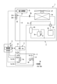
- FIG. 1 is a circuit diagram schematically showing the configuration of the air conditioner 1 according to the present embodiment.
- the air conditioner 1 includes an outdoor unit 2, an air handling unit 3, an expansion valve kit 4, and an interface controller (hereinafter, simply referred to as a controller) 5.
- the outdoor unit 2 and the air handling unit 3 are connected by a flow path 6 for circulating a refrigerant via an expansion valve kit 4.
- the controller 5 is connected to the outdoor unit 2, the air handling unit 3, and the expansion valve kit 4 by wire or wirelessly, respectively, and performs data communication for operation control with each of these elements.
- the outdoor unit 2 has, as main elements, a compressor 2a, an oil separator 2b, a check valve 2c, a four-way valve 2d, a heat exchanger (hereinafter referred to as an outdoor heat exchanger) 2e, a blower (hereinafter referred to as an outdoor fan) 2f, and the like. It is equipped with an expansion valve (hereinafter referred to as an outdoor expansion valve) 2g, an accumulator 2h, and a suction cup 2i. Each element other than the outdoor fan 2f is sequentially connected by piping and arranged in a flow path 6 connected to the air handling unit 3 via the expansion valve kit 4. The outdoor fan 2f is arranged adjacent to the outdoor heat exchanger 2e.
- the outdoor unit 2 includes a capacity calculation unit 2j and a setting unit 2k.
- the capacity calculation unit 2j includes a CPU, a memory, a storage device (non-volatile memory), an input / output circuit, a timer, and the like, and executes a predetermined calculation process.
- the capacity calculation unit 2j controls the operation of each element of the outdoor unit 2 and controls the operation of the air handling unit 3 and the expansion valve kit 4 in cooperation with the controller 5.
- the capacity calculation unit 2j can directly control the operating frequency of the compressor 2a and the opening / closing operation of the indoor expansion valve 4a of the expansion valve kit 4 described later.
- the capacity calculation unit 2j assigns an execution command for the control to the control unit 5a of the controller 5, which will be described later, and opens / closes the indoor expansion valve 4a via the control unit 5a.
- the opening degree of the indoor expansion valve 4a may be adjusted by indirectly controlling the operation.
- the setting unit 2k has a first setting unit 21k and a second setting unit 22k.
- the first setting unit 21k controls the opening / closing operation of the indoor expansion valve 4a, which will be described later, specifically, the opening degree of the indoor expansion valve 4a and the change cycle of the opening degree are controlled by either the capacity calculation unit 2j or the control unit 5a. Set whether to do it.
- the second setting unit 22k sets whether to adjust the opening degree of the indoor expansion valve 4a and the change cycle of the opening degree, or the operation frequency of the compressor 2a and the change cycle of the operation frequency. do.
- These setting units 21k and 22k are composed of, for example, an operation panel, switches, buttons, a display for display, etc. that face the outside when the door (not shown) of the housing 21 is opened.
- the first setting unit 21k and the second setting unit 22k may have one configuration that has functions of each other, or may have an independent configuration. Further, the setting unit 2k may be provided alternately with the setting unit 3d of the air handling unit 3 described later, and may be omitted when the setting unit 3d is present.
- the air handling unit 3 includes a heat exchanger (hereinafter referred to as an indoor heat exchanger) 3a, a blower (hereinafter referred to as an indoor fan) 3b, a detection unit 3c, and a setting unit 3d as main elements. Although only one air handling unit 3 is shown in FIG. 1 as an example, there may be a plurality of air handling units 3.
- the indoor heat exchanger 3a is arranged on the piping in the housing 31 forming the flow path 6 connected to the outdoor unit 2 via the expansion valve kit 4.
- the indoor fan 3b is arranged adjacent to the indoor heat exchanger 3a in the housing 31.
- the housing 31 defines the outer shell of the air handling unit 3.
- the detection unit 3c is an element that detects the temperature of each target in the air handling unit 3 as follows, and is a temperature sensor such as a thermistor.
- the detection unit 3c includes four detection units 31c, 32c, 33c, 34c.
- the first detection unit 31c is arranged close to the indoor fan 3b, and is temperature-controlled by heat exchange in the indoor heat exchanger 3a to control the temperature of the air blown out from the indoor fan 3b (hereinafter referred to as blowout temperature).
- the second detection unit 32c is arranged in the flow path 6 on the liquid refrigerant side of the indoor heat exchanger 3a, and measures the temperature of the liquid refrigerant flowing in or out of the indoor heat exchanger 3a (hereinafter referred to as the liquid refrigerant temperature). To detect.
- the third detection unit 33c is arranged in the flow path 6 on the gas refrigerant side of the indoor heat exchanger 3a, and determines the temperature of the gas refrigerant flowing in or out of the indoor heat exchanger 3a (hereinafter referred to as gas refrigerant temperature). To detect.
- the fourth detection unit 34c is arranged in the flow path 6 between the second detection unit 32c and the third detection unit 33c, and detects the temperature of the refrigerant (hereinafter referred to as the intermediate refrigerant temperature) between them.
- Each of the detection units 31c, 32c, 33c, and 34c assigns the detected temperature value to the control unit 5a of the controller 5, which will be described later.
- the setting unit 3d has a first setting unit 31d and a second setting unit 32d.
- the first setting unit 31d controls the opening / closing operation of the indoor expansion valve 4a of the expansion valve kit 4, which will be described later, specifically, the opening degree of the indoor expansion valve 4a and the change cycle of the opening degree are determined by the capacity calculation unit 2j or the capacity calculation unit 31d. Which of the control units 5a of the controller 5 to be described later is used is set.
- the second setting unit 32d sets whether to adjust the opening degree of the indoor expansion valve 4a and the change cycle of the opening degree, or the operation frequency of the compressor 2a and the change cycle of the operation frequency. do.
- These setting units 31d and 32d are remote controllers of the air handling unit 3 including, for example, an operation panel, a switch, a button, a display for display, and the like.
- the first setting unit 31d and the second setting unit 32d may have one configuration that also has mutual functions, or may have independent configurations. Further, the setting unit 3d may be provided alternately with the setting unit 2k of the outdoor unit 2, and can be omitted when the setting unit 2k is present.
- the expansion valve kit 4 includes an expansion valve (hereinafter referred to as an indoor expansion valve) 4a as a main element.
- the air handling unit 3 includes an indoor heat exchanger 3a and an indoor fan 3b, but does not have an expansion valve for controlling its air conditioning capacity. Therefore, the expansion valve kit 4 is provided in the air conditioner 1 as an optional device for controlling the air conditioning capacity of the air handling unit 3.
- the indoor expansion valve 4a is connected by piping between the outdoor unit 2 and the air handling unit 3 in the housing 41, and is arranged in the flow path 6 connecting these units 2 and 3.
- the housing 41 defines the outer shell of the expansion valve kit 4.
- the controller 5 controls the operations of the outdoor unit 2, the air handling unit 3, and the expansion valve kit 4. Further, the controller 5 can give a command to the outdoor unit 2 to control the operation of the outdoor unit 2, the air handling unit 3, and the expansion valve kit 4.
- the controller 5 includes a control unit 5a that executes such control.
- the control unit 5a includes a CPU, a memory, a storage device (non-volatile memory), an input / output circuit, a timer, and the like, and executes a predetermined arithmetic process.
- the control unit 5a controls the operation of the detection unit 3c of the air handling unit 3 and analyzes each temperature value acquired from the detection unit 3c.
- the control unit 5a controls the opening / closing operation of the indoor expansion valve 4a, controls the operating frequency of the compressor 2a, and the like.
- the control unit 5a can execute the control by its own execution command, or can execute the control in response to the execution command from the capacity calculation unit 2j. Is.
- the control unit 5a assigns an execution command for the control to the capacity calculation unit 2j of the outdoor unit 2 and controls the drive of the compressor 2a via the capacity calculation unit 2j. And adjust the operating frequency.
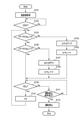
- FIG. 2 shows a control flow of the control unit 5a at the time of capacity control of the air handling unit 3.
- the control unit 5a causes the detection unit 3c to start temperature detection and acquires a detection result (temperature value) (S101).
- the control unit 5a operates the detection units 31c, 32c, 33c, and 34c to acquire the detection values of the blowout temperature, the liquid refrigerant temperature, the gas refrigerant temperature, and the intermediate refrigerant temperature.
- the control unit 5a determines the condition for determining whether or not the ability of the air handling unit 3 can be determined.
- the capacity availability determination condition is a determination condition of whether or not the air conditioning capacity of the air handling unit 3 can be appropriately determined, and the air conditioner 1 is continuously operated for a reference time from the start of operation. It is determined by whether or not it is present. After the start of operation of the air conditioner 1 until the reference time elapses, the operating state of the air conditioner 1 may not be stable and the air conditioning capacity of the air handling unit 3 may not be properly sampled. Therefore, the reference time is preset as the continuous operation time of the air conditioner 1 required to appropriately determine the air conditioning capacity of the air handling unit 3.
- the reference time is stored in, for example, the storage device of the control unit 5a, and is read out into the memory when the ability determination possibility condition is determined.
- the value of the reference time can be arbitrarily set according to the performance of the air conditioner 1, for example, about 10 minutes.
- the control unit 5a compares the operating time (t) of the air conditioner 1 with the reference time (t0), and determines whether or not the operating time is equal to or longer than the reference time (t ⁇ t0). Judgment (S102).
- the operation time is the elapsed time from the start of operation to the time when the ability determination possibility condition is determined.
- the control unit 5a repeats the determination of the ability determination possibility condition until the operation time becomes equal to or longer than the reference time (t ⁇ t0).
- the control unit 5a determines the capacity determination condition of the air handling unit 3.
- the capacity determination condition is a condition for determining the air conditioning capacity of the air handling unit 3 during operation of the air conditioner 1, and is determined according to the capacity determination condition parameter.
- the capacity determination condition parameter is the value of the amount of change ((TF-TFO) / t n ) of the temperature difference between the blowout temperature (TF) and the target blowout temperature (TFO) per predetermined time (t n ).
- the blowout temperature (TF) is detected by the first detection unit 31c and is given to the control unit 5a.
- the target blowing temperature (TFO) is the target temperature of the air that is temperature-controlled and blown out in the air handling unit 3, and finally corresponds to the set indoor temperature.
- the value of the target blowout temperature (TFO) is set by the user, for example, via the setting unit 3d, and is held in the memory of the control unit 5a.
- the temperature difference (TF-TFO) between the outlet temperature and the target outlet temperature is an absolute value.
- the predetermined time (t n ) is preset as a time interval for determining the ability of the air handling unit 3, that is, a determination interval (sampling time) for the ability determination condition.
- the sampling time (t n ) is stored in the storage device of the control unit 5a, for example, and is read out into the memory when the ability determination condition is determined.
- the sampling time can be arbitrarily set according to the capacity of the air handling unit 3, and is set to an initial value of about 1 minute to 10 minutes so as not to exceed the reference time, for example.
- the first threshold value (X) is preset as a value that defines the upper limit of the ability determination condition parameter.
- the second threshold value (Y) is preset as a value that defines the lower limit of the ability determination condition parameter.
- the first threshold value and the second threshold value are stored in the storage device of the control unit 5a, for example, and are read out to the memory when the ability determination condition is determined.
- These threshold values can be arbitrarily set according to the air conditioning capacity of the air handling unit 3, for example, the first threshold value is about 10 ° C. and the second threshold value is about 3 ° C.
- the control unit 5a calculates the value of the ability determination condition parameter ((TF-TFO) / tn ) and compares the calculated value with the first threshold value (X). For example, the control unit 5a determines whether or not the value of the ability determination condition parameter exceeds the first threshold value ((TF-TFO) / tn > X) (S103).
- the control unit 5a increases the opening change amount ( ⁇ PLS) of the indoor expansion valve 4a, and the indoor expansion valve 4a is increased according to the opening change amount.
- the opening value is adjusted (S104).
- the amount of change in the opening degree of the indoor expansion valve 4a is a scale indicating the degree of opening of the indoor expansion valve 4a, and is a fluctuation value that fluctuates according to the value of the capacity determination condition parameter. For example, the larger the value of the capacity determination condition parameter, the larger the opening change amount.
- the value of the opening degree change amount is stored in the storage device of the control unit 5a as a table in association with the value of the capacity determination condition parameter, for example, and is read out to the memory when the opening degree change amount is adjusted.
- the sampling time (t n ) is a time interval until the next determination of the capacity determination condition, and corresponds to a change cycle of the opening degree of the indoor expansion valve 4a, or a change cycle of the opening degree change amount ( ⁇ PLS) in the present embodiment. do.
- the predetermined time ( ⁇ ) is the adjustment time of the sampling time (t n ), and can be arbitrarily set according to the air conditioning capacity of the air handling unit 3 and the like.
- the adjustment time ( ⁇ ) is, for example, a value of about 10% of the sampling time, and if the sampling time is about 1 minute to 10 minutes, it is about 0.1 minute to 1 minute.
- the control unit 5a sets the value of the ability determination condition parameter to the second threshold value. Compare with (Y). For example, the control unit 5a determines whether or not the value of the ability determination condition parameter is less than the second threshold value ((TF-TFO) / t n ⁇ Y) (S106).
- the control unit 5a lowers the opening change amount ( ⁇ PLS) of the indoor expansion valve 4a, and opens the indoor expansion valve 4a according to the opening change amount. Adjust the degree (S107). As a result, the opening of the indoor expansion valve 4a becomes smaller than that before the adjustment.
- the amount of change in the opening degree of the indoor expansion valve 4a may be, for example, the smaller the value of the capacity determination condition parameter, the smaller the amount of change.
- the adjustment time ( ⁇ ) is matched with the value at the time of shortening the sampling time (t n ) (S105), but it may be different.
- the air conditioner 1 in the control unit 5a has a sampling time (t n ). It is determined whether or not the air conditioner is continuously operated (S109). For example, the control unit 5a determines whether or not the operating time of the air conditioner 1 is equal to or longer than the sampling time (t ⁇ t n ). In this case, it corresponds to the case where the value of the ability determination condition parameter is equal to or more than the second threshold value and equal to or less than the first threshold value in the determination of the ability determination condition. In this case, the opening degree change amount ( ⁇ PLS) of the indoor expansion valve 4a is maintained without being adjusted, and the sampling time is maintained at the value at the time of the previous capacity determination.
- ⁇ PLS opening degree change amount
- the control unit 5a makes the same determination (S109).
- the control unit 5a determines the operation stop condition of the air conditioner 1 until the air conditioner 1 is continuously operated over the sampling time (t n ) (S111).
- the operation stop condition is a determination condition for whether or not to stop the operation of the air conditioner 1, and is determined according to, for example, whether or not the control unit 5a has received a signal indicating that the air conditioner 1 has been stopped.
- the signal indicating the stop of operation is transmitted, for example, by the operator or the user selecting the stop of operation from the setting unit 2k of the outdoor unit 2 or the setting unit 3d of the air handling unit 3.
- the control unit 5a When the operation stop condition is not satisfied, the control unit 5a repeatedly determines whether or not the air conditioner 1 is continuously operated (t ⁇ t n ) over the sampling time (S109). On the other hand, when the operation stop condition is satisfied, the control unit 5a stops the operation of the air conditioner 1 (S112). That is, while the air conditioner 1 is being operated, a series of processes for executing the capacity control of the air handling unit 3 is repeated. Then, when the operation of the air conditioner 1 is stopped, a series of processes for executing the capacity control of the air handling unit 3 is also completed.
- the opening degree change amount of the indoor expansion valve 4a ( ⁇ PLS) can be increased and the sampling time (t n ) can be shortened.
- the value of the capacity determination condition parameter exceeds the first threshold value, it corresponds to the case where the temperature difference between the blowout temperature (TF) and the target blowout temperature (TFO) is large. Therefore, in this case, by increasing the opening change amount of the indoor expansion valve 4a and shortening the sampling time, the determination interval of the capacity determination condition, that is, the change cycle of the opening change amount of the indoor expansion valve 4a can be shortened. .. Therefore, the opening degree of the indoor expansion valve 4a can be adjusted in a short cycle, and the blowing temperature in the air handling unit 3 can be reached more quickly to the target blowing temperature.
- the opening change amount ( ⁇ PLS) of the indoor expansion valve 4a is reduced and the sampling time ( t n ) can be extended.
- the value of the capacity determination condition parameter is less than the second threshold value, the temperature difference between the blowout temperature (TF) and the target blowout temperature (TFO) is small, which corresponds to a hunting state. Therefore, in this case, the change cycle of the opening change amount of the indoor expansion valve 4a can be extended by reducing the opening change amount of the indoor expansion valve 4a and extending the sampling time.
- the opening degree of the indoor expansion valve 4a can be adjusted in a long cycle, that is, the change cycle of the opening degree change amount of the indoor expansion valve 4a can be delayed as compared with the case where the temperature difference between the blowing temperature and the target blowing temperature is large.
- the outlet temperature can be reached to the target outlet temperature more efficiently.
- the opening degree change amount of the indoor expansion valve 4a can be maintained without adjustment, and the sampling time can be set at the time of the previous capacity determination. Can be maintained at the value of.
- the value of the capacity determination condition parameter is equal to or greater than the second threshold value and equal to or less than the first threshold value, it corresponds to the case where the temperature difference between the outlet temperature and the target outlet temperature is relatively stable. Therefore, in this case, by maintaining the opening change amount of the indoor expansion valve 4a and the sampling time, the change cycle of the opening change amount of the indoor expansion valve 4a can be maintained as it is. Therefore, the blowing temperature can be appropriately reached to the target blowing temperature in both the case where the temperature difference between the blowing temperature and the target blowing temperature is large and the case where the temperature difference is small.
- the adjustment of the opening degree change amount and the change cycle of the opening degree change amount of these indoor expansion valves 4a is performed by the control unit 5a, that is, the controller 5. Therefore, for example, even if the air handling unit 3 is manufactured by a third party different from the outdoor unit 2, the expansion valve kit 4, and the controller 5, the air conditioning capacity of the air handling unit 3 can be appropriately controlled. Therefore, it is possible to stabilize the behavior of the refrigeration cycle in the air conditioner 1 including the third-party air handling unit 3.
- the adjustment of the opening degree change amount of the indoor expansion valve 4a and the change cycle of the opening degree change amount may be performed not by the control unit 5a, that is, the controller 5, but by the outdoor unit 2, specifically, the capacity calculation unit 2j. good.
- the capacity calculation unit 2j an embodiment in which such adjustment is performed by the capacity calculation unit 2j will be described as a second embodiment.
- the configuration of the air conditioner 1 in the second embodiment is the same as that in the first embodiment (FIG. 1). Therefore, in the following, the description of the configuration of the air conditioner will be omitted (see FIG. 1), and an example of the capacity control of the air handling unit 3 in the second embodiment will be described.
- control contents are the same as each step (S101 to S111) of the control flow of the first embodiment shown in FIG. 2, but each control entity is different. Therefore, in the explanation of the second embodiment, the control flow shown in FIG. 2 is taken into consideration.
- the capacity control of the air handling unit 3 including the adjustment of the opening degree change amount of the indoor expansion valve 4a and the change cycle of the opening degree change amount is mainly executed by the capacity calculation unit 2j of the outdoor unit 2.
- the capacity calculation unit 2j acquires the detected value (temperature value) of the temperature detected by the detection unit 3c from the control unit 5a (S101). Specifically, the capacity calculation unit 2j acquires the detected values of the blowout temperature, the liquid refrigerant temperature, the gas refrigerant temperature, and the intermediate refrigerant temperature detected by the detection units 31c, 32c, 33c, and 34c.
- the capacity calculation unit 2j determines the capacity determination availability condition of the air handling unit 3. In determining the capability determination availability condition, the capability calculation unit 2j compares the operating time (t) of the air conditioner 1 with the reference time (t0), and determines whether the operating time is equal to or longer than the reference time (t ⁇ t0). Is determined (S102). The ability calculation unit 2j repeats the determination of the ability determination possibility condition until the operation time becomes equal to or longer than the reference time.
- the capacity calculation unit 2j determines the capacity determination condition of the air handling unit 3. In determining the ability determination condition, the ability calculation unit 2j calculates the value of the ability determination condition parameter ((TF-TFO) / t n ) and compares the calculated value with the first threshold value (X). For example, the ability calculation unit 2j determines whether or not the value of the ability determination condition parameter exceeds the first threshold value ((TF-TFO) / tn > X) (S103).
- the capacity calculation unit 2j increases the opening change amount ( ⁇ PLS) of the indoor expansion valve 4a, and the indoor expansion valve 4a is increased according to the opening change amount.
- the opening degree of is adjusted (S104).
- the capacity calculation unit 2j assigns an execution command for the control to the control unit 5a.
- the control unit 5a operates the indoor expansion valve 4a in order to increase the opening degree change amount of the indoor expansion valve 4a and adjust the opening degree of the indoor expansion valve 4a according to the opening degree change amount. ..
- the ability calculation unit 2j sets the value of the ability determination condition parameter to the second threshold value. Compare with the threshold (Y). For example, the ability calculation unit 2j determines whether or not the value of the ability determination condition parameter is less than the second threshold value ((TF-TFO) / t n ⁇ Y) (S106).
- the capacity calculation unit 2j lowers the opening change amount ( ⁇ PLS) of the indoor expansion valve 4a, and the indoor expansion valve 4a responds to the opening change amount.
- the opening degree is adjusted (S107).
- the capacity calculation unit 2j gives an execution command for the control to the control unit 5a.
- the control unit 5a operates the indoor expansion valve 4a in order to increase the opening degree change amount of the indoor expansion valve 4a and adjust the opening degree of the indoor expansion valve 4a according to the opening degree change amount. ..
- the capacity calculation unit 2j extends the sampling time (t n ).
- the air conditioner 1 in the capacity calculation unit 2j has a sampling time (t n) . ), It is determined whether or not the vehicle is continuously operated (S109).
- the capacity calculation unit 2j makes the same determination (S109).
- the capacity calculation unit 2j determines the operation stop condition of the air conditioner 1 until the air conditioner 1 is continuously operated over the sampling time (t n ) (S111).
- the operation stop condition is determined according to, for example, whether or not the capacity calculation unit 2j has received a signal indicating that the operation of the air conditioner 1 has been stopped.
- the capacity calculation unit 2j When the operation stop condition is not satisfied, the capacity calculation unit 2j repeatedly determines whether or not the air conditioner 1 is continuously operated over the sampling time (t n ) (S109). On the other hand, when the operation stop condition is satisfied, the capacity calculation unit 2j stops the operation of the air conditioner 1 (S112).
- the opening change amount of the indoor expansion valve 4a and the change cycle of the opening change amount are adjusted by the capacity calculation unit 2j, that is, the outdoor unit 2. Therefore, this embodiment has the following effects in addition to the same effects as those of the first embodiment described above. That is, according to the present embodiment, even when the air conditioner 1 is provided with a plurality of air handling units 3, the capacity calculation is performed on the opening degree change amount and the opening degree change amount change cycle of the indoor expansion valve 4a.
- the unit 2j can be centrally adjusted, and the air conditioning capacity of each air handling unit 3 can be collectively managed by the outdoor unit 2.
- the opening degree change amount and the opening degree change amount change cycle of the indoor expansion valve 4a are adjusted, respectively. ..
- the capacity control of the air handling unit 3 can be performed by other than adjusting the opening degree change amount of the indoor expansion valve 4a and the change cycle thereof.
- embodiments in which the capacity of the air handling unit 3 is controlled by adjusting the operating frequency of the compressor 2a of the outdoor unit 2 will be described as the third embodiment and the fourth embodiment.
- the third embodiment is an embodiment in which the subject of control is the control unit 5a
- the fourth embodiment is an embodiment in which the subject of control is the capacity calculation unit 2j.
- the configuration of the air conditioner 1 in these embodiments is the same as that of the first embodiment (FIG. 1). Therefore, in the following, the description of the configuration of the air conditioner will be omitted (see FIG. 1), and an example of the capacity control of the air handling unit 3 in these embodiments will be described.
- FIG. 3 shows a control flow of the control unit 5a at the time of capacity control of the air handling unit 3 in the present embodiment.
- the control flow of the control unit 5a replaces a part of the control flow of the first embodiment shown in FIG. 2 with the control peculiar to the third embodiment. Therefore, the control equivalent to the first embodiment described above will be given the same step number to simplify the description, and only the control specific to the third embodiment will be described in detail.
- the control unit 5a detects the blowout temperature, the liquid refrigerant temperature, the gas refrigerant temperature, and the intermediate refrigerant temperature from the detection units 31c, 32c, 33c, and 34c.
- the value (temperature value) is acquired (S101), and the condition for determining the ability of the air handling unit 3 is determined.
- the control unit 5a determines whether or not the operating time of the air conditioner 1 is equal to or longer than the reference time (t ⁇ t0) (S102).
- the control unit 5a determines whether or not the value of the capacity determination condition parameter exceeds the first threshold value ((TF-TFO) / t n > X) ((TF-TFO) / t n> X). S103).
- the control unit 5a When the value of the capacity determination condition parameter exceeds the first threshold value, the control unit 5a increases the frequency change amount ( ⁇ Hz) of the compressor 2a and adjusts the operating frequency of the compressor 2a according to the frequency change amount. (S301).
- the control unit 5a assigns an execution command for the control to the capacity calculation unit 2j.
- the capacity calculation unit 2j operates the compressor 2a in order to increase the frequency change amount of the compressor 2a and adjust the operating frequency of the compressor 2a according to the frequency change amount. As a result, the operating frequency of the compressor 2a becomes higher than that before the adjustment.
- the frequency change amount of the compressor 2a is a measure showing the degree of change of the operating frequency of the compressor 2a, and is a fluctuation value that fluctuates according to the value of the capacity determination condition parameter. For example, the larger the value of the capability determination condition parameter, the larger the frequency change amount.
- the value of the frequency change amount is stored in the storage device of the control unit 5a as a table in association with the value of the ability determination condition parameter, for example, and is read out to the memory when the frequency change amount is adjusted.
- the sampling time (t n ) is a time interval until the next determination of the capacity determination condition, and corresponds to a change cycle of the operating frequency of the compressor 2a, or a change cycle of the frequency change amount ( ⁇ Hz) in the present embodiment.
- the predetermined time ( ⁇ ) is the adjustment time of the sampling time (t n ), and can be arbitrarily set according to the air conditioning capacity of the air handling unit 3 and the like.
- the predetermined time ( ⁇ ) is the same as the adjustment time ( ⁇ ) in the first embodiment described above, but may be different.
- the control unit 5a has the ability determination condition parameter value as the second threshold value. It is determined whether or not it is less than ((TF-TFO) / t n ⁇ Y) (S106).
- the control unit 5a When the value of the capacity determination condition parameter is less than the second threshold value, the control unit 5a lowers the frequency change amount ( ⁇ Hz) of the compressor 2a and adjusts the operating frequency of the compressor 2a according to the frequency change amount. (S302).
- the control unit 5a assigns an execution command for the control to the capacity calculation unit 2j.
- the capacity calculation unit 2j operates the compressor 2a in order to reduce the frequency change amount of the compressor 2a and adjust the operating frequency of the compressor 2a according to the frequency change amount.
- the operating frequency of the compressor 2a becomes smaller than that before the adjustment.
- the frequency change amount of the compressor 2a may be, for example, the smaller the value of the capacity determination condition parameter, the smaller the change amount.
- the predetermined time ( ⁇ ) here is the same as the value at the time of shortening the sampling time (t n ) (S105), but it may be different.
- the control unit 5a continues the air conditioner 1 over the sampling time. (S109), it is determined whether or not the air conditioner is being operated (t ⁇ t n ). In this case, it corresponds to the case where the value of the ability determination condition parameter is equal to or more than the second threshold value and equal to or less than the first threshold value in the determination of the ability determination condition. In this case, the frequency change amount ( ⁇ Hz) of the compressor 2a is maintained without being adjusted, and the sampling time is maintained at the value at the time of the previous capacity determination.
- ⁇ Hz frequency change amount
- the control unit 5a makes the same determination (S109).
- control unit 5a determines the operation stop condition of the air conditioner 1 until the air conditioner 1 is continuously operated over the sampling time (t n ) (S111). If the operation stop condition is not satisfied, the control unit 5a repeatedly determines whether or not the air conditioner 1 is continuously operated over the sampling time (t n ) (S109). On the other hand, when the operation stop condition is satisfied, the control unit 5a stops the operation of the air conditioner 1 (S112).
- the frequency change amount ( ⁇ Hz) of the compressor 2a is determined.
- the sampling time (t n ) can be shortened as well as increased.
- the value of the capacity determination condition parameter exceeds the first threshold value, it corresponds to the case where the temperature difference between the blowout temperature (TF) and the target blowout temperature (TFO) is large. Therefore, in this case, by increasing the frequency change amount of the compressor 2a and shortening the sampling time, the determination interval of the capacity determination condition, that is, the change cycle of the frequency change amount of the compressor 2a can be shortened. Therefore, the operating frequency of the compressor 2a can be adjusted in a short cycle, and the blowing temperature in the air handling unit 3 can be reached more quickly to the target blowing temperature.
- the frequency change amount ( ⁇ Hz) of the compressor 2a is lowered and the sampling time (t n ) is reduced. ) Can be extended.
- the value of the capacity determination condition parameter is less than the second threshold value, the temperature difference between the blowout temperature (TF) and the target blowout temperature (TFO) is small, which corresponds to a hunting state. Therefore, in this case, the frequency change amount of the compressor 2a can be extended by reducing the frequency change amount of the compressor 2a and extending the sampling time.
- the operating frequency of the compressor 2a can be adjusted in a long cycle, that is, the change cycle of the frequency change amount of the compressor 2a can be delayed as compared with the case where the temperature difference between the blowout temperature and the target blowout temperature is large, and the blowout temperature can be adjusted. It is possible to reach the target blowing temperature more efficiently.
- the frequency change amount of the compressor 2a can be maintained without adjustment, and the sampling time can be set to the value at the time of the previous capacity determination. Can be maintained.
- the value of the capacity determination condition parameter is equal to or greater than the second threshold value and equal to or less than the first threshold value, it corresponds to the case where the temperature difference between the outlet temperature and the target outlet temperature is relatively stable. Therefore, in this case, by maintaining the frequency change amount of the compressor 2a and the sampling time, the change cycle of the frequency change amount of the compressor 2a can be maintained as it is. Therefore, the blowing temperature can be appropriately reached to the target blowing temperature in both the case where the temperature difference between the blowing temperature and the target blowing temperature is large and the case where the temperature difference is small.
- the frequency change amount and the frequency change amount change cycle of the compressor 2a are adjusted. Therefore, since the circulation amount of the refrigerant in the entire air conditioner 1 can be adjusted, the behavior of the refrigeration cycle can be stabilized.
- the frequency change amount of the compressor 2a may be adjusted in addition to the adjustment of the opening degree change amount of the indoor expansion valve 4a.
- the process of step S104 shown in FIG. 2 may be performed before or after the process of step S301 shown in FIG.
- the process of step S107 shown in FIG. 2 may be performed before or after the process of step S302 shown in FIG.
- both the adjustment of the frequency change amount of the compressor 2a and the adjustment of the opening degree change amount of the indoor expansion valve 4a can be executed.
- the air conditioning capacity of the air handling unit 3 can be appropriately controlled, and the air conditioner 1 can be refrigerated. It is possible to stabilize the behavior of the cycle as in the first embodiment.
- the capacity control of the air handling unit 3 including the adjustment of the opening degree change amount of the indoor expansion valve 4a and the change cycle of the opening degree change amount is mainly executed by the capacity calculation unit 2j of the outdoor unit 2.
- the control contents are the same as each step of the control flow of the third embodiment shown in FIG. 3, but each control entity is different. Therefore, in the explanation of the fourth embodiment, the control flow shown in FIG. 3 is taken into consideration.
- the capacity calculation unit 2j obtains detection values (temperature values) of the blowout temperature, the liquid refrigerant temperature, the gas refrigerant temperature, and the intermediate refrigerant temperature from the detection units 31c, 32c, 33c, and 34c. It is acquired (S101), and the condition for determining whether or not the ability of the air handling unit 3 can be determined is determined.
- the capability calculation unit 2j determines whether or not the operating time of the air conditioner 1 is equal to or longer than the reference time (t ⁇ t0) (S102). Then, when the operation time becomes equal to or longer than the reference time, the capacity calculation unit 2j determines whether or not the value of the capacity determination condition parameter exceeds the first threshold value ((TF-TFO) / t n > X). (S103).
- the capacity calculation unit 2j increases the frequency change amount ( ⁇ Hz) of the compressor 2a and sets the operating frequency of the compressor 2a according to the frequency change amount. Adjust (S301). As a result, the operating frequency of the compressor 2a becomes higher than that before the adjustment.
- the ability calculation unit 2j has the ability determination condition parameter value of the second value. It is determined whether or not it is less than the threshold value ((TF-TFO) / t n ⁇ Y) (S106).
- the capacity calculation unit 2j lowers the frequency change amount ( ⁇ Hz) of the compressor 2a and adjusts the operating frequency of the compressor 2a according to the frequency change amount. (S302). As a result, the operating frequency of the compressor 2a becomes smaller than that before the adjustment.
- the capacity calculation unit 2j extends the sampling time (t n ).
- the control unit 5a extends the sampling time (t n ) at the time of the current ability determination condition determination by a predetermined time ( ⁇ ) from the sampling time (t n-1 ) at the time of the previous ability determination condition determination (n).
- t n t n-1 + ⁇ ) (S108).
- the predetermined time ( ⁇ ) here is the same as the value at the time of shortening the sampling time (t n ) (S105), but it may be different.
- the air conditioner 1 in the capacity calculation unit 2j has a sampling time (t n) . ), It is determined whether or not the vehicle is continuously operated (S109). In this case, the frequency change amount ( ⁇ Hz) of the compressor 2a is maintained without being adjusted, and the sampling time is maintained at the value at the time of the previous capacity determination.
- the capacity calculation unit 2j makes the same determination (S109).
- the capacity calculation unit 2j determines the operation stop condition of the air conditioner 1 until the air conditioner 1 is continuously operated over the sampling time (t n ) (S111). When the operation stop condition is not satisfied, the capacity calculation unit 2j repeatedly determines whether or not the air conditioner 1 is continuously operated over the sampling time (t n ) (S109). On the other hand, when the operation stop condition is satisfied, the capacity calculation unit 2j stops the operation of the air conditioner 1 (S112).
- the frequency change amount of the compressor 2a and the change cycle of the frequency change amount are adjusted by the capacity calculation unit 2j, that is, the outdoor unit 2. Therefore, this embodiment has the following effects in addition to the same effects as those of the third embodiment described above. That is, according to the present embodiment, even when the air conditioner 1 includes a plurality of air handling units 3, the capacity calculation unit 2j can change the frequency change amount and the frequency change amount of the compressor 2a. It can be adjusted centrally, and the air conditioning capacity of each air handling unit 3 can be collectively managed by the outdoor unit 2.
- the value of the amount of change ((TF-TFO) / t n ) is used.
- the value of the ability determination condition parameter is not limited to this, and other values can be used.
- an embodiment using a value other than the value of the change amount ((TF-TFO) / t n ) of the temperature difference between the blowout temperature and the target blowout temperature per predetermined time will be described as the fifth embodiment.
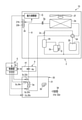
- FIG. 4 is a circuit diagram schematically showing the configuration of the air conditioner 10 according to the present embodiment.
- the configuration of the air conditioner 10 in the fifth embodiment is basically the same as the configuration of the air conditioner 1 (FIG. 1) in the first embodiment. Specifically, therefore, the same or similar configurations as those of the air conditioner 1 are designated by the same reference numerals on the drawings, and the description thereof will be omitted.
- the air handling unit 30 includes a heat exchanger (, indoor heat exchanger) 3a, a blower (indoor fan) 3b, a detection unit 3c, and a setting unit 3d as main elements. Although only one air handling unit 30 is shown in FIG. 1 as an example, there may be a plurality of air handling units 30.
- the detection unit 3c includes four detection units 32c, 33c, 34c, 35c. That is, in the example shown in FIG. 4, a fifth detection unit 35c is provided in place of the first detection unit 31c in the example shown in FIG.
- These detection units 32c, 33c, 34c, 35c are temperature sensors such as a thermistor.
- the fifth detection unit 35c is arranged near, for example, a suction port (not shown) of air (indoor air) in an indoor space formed in the housing 31, and is the temperature of the indoor air sucked by the indoor fan 3b (hereinafter,). , Called suction temperature) is detected.
- the indoor air is sucked into the housing 31 from the suction port by driving the indoor fan 3b, and the temperature is controlled by heat exchange in the indoor heat exchanger 3a. That is, the suction temperature corresponds to the temperature of the indoor air before the temperature is adjusted by the heat exchange in the indoor heat exchanger 3a, in short, the indoor temperature.
- the fifth detection unit 35c applies the detected suction temperature to the control unit 5a of the controller 5.
- the fifth detection unit 35c may be provided in addition to the detection unit 3c of the example shown in FIG. 1, or may coexist with the first detection unit 31c.
- the value is used.
- the target suction temperature (TAO) is the target temperature of the air sucked in before the temperature is adjusted by the air handling unit 3, and finally corresponds to the set indoor temperature.
- the value of the target suction temperature (TAO) is set by the user, for example, via the setting unit 3d, and is held in the memory of the control unit 5a.
- the temperature difference between the suction temperature (TA) and the target suction temperature (TAO) is an absolute value.
- the control unit 5a or the capacity calculation unit 2j determines the capacity determination condition parameter ((TA) according to the values of the suction temperature (TA) and the target suction temperature (TAO). -TAO) / t n ) values are calculated and the calculated values are compared with the first threshold value (X) and the second threshold value (Y). For example, the control unit 5a or the capacity calculation unit 2j determines whether or not the value of the capacity determination condition parameter exceeds the first threshold value ((TA-TAO) / t n > X). Further, for example, the control unit 5a or the capacity calculation unit 2j determines whether or not the value of the capacity determination condition parameter is less than the second threshold value ((TA-TAO) / t n ⁇ Y).
- FIG. 5 and 6 show the control flow of the control unit 5a or the capacity calculation unit 2j at the time of capacity control of the air handling unit 30 according to the present embodiment.
- FIG. 5 is a control flow in the case of adjusting the opening degree change amount of the indoor expansion valve 4a and the change cycle of the opening degree change amount, respectively.
- FIG. 6 is a control flow in the case of adjusting the frequency change amount of the compressor 2a and the change cycle of the frequency change amount.
- the capacity determination condition parameter ((TA-TAO) / t n ).
- the value of may be compared with the first threshold value (X) and the second threshold value (Y) to determine the ability determination condition.
- the other control contents are the same as each step (FIG. 2) of the control flow of the first embodiment and the second embodiment described above.
- the value of the capacity determination condition parameter ((TA-TAO) / tn ) is set to the second value.
- the ability determination condition may be determined by comparing with the threshold value (X) of 1 and the threshold value (Y) of the second.
- the other control contents are the same as each step (FIG. 3) of the control flow of the third embodiment and the fourth embodiment described above.
- Expansion valve indoor expansion valve
- 5 ... Interface controller controller
- 5a ... Control unit 6
- 6 Flow path
- 21k First setting unit
- 22k Second setting unit
- 31c ... 1st detection unit
- 32c ... 2nd detection unit
- 33c ... 3rd detection unit
- 34c ... 4th detection unit
- 35c ... 5th detection unit.
Landscapes
- Engineering & Computer Science (AREA)
- Mechanical Engineering (AREA)
- General Engineering & Computer Science (AREA)
- Physics & Mathematics (AREA)
- Thermal Sciences (AREA)
- Chemical & Material Sciences (AREA)
- Combustion & Propulsion (AREA)
- Signal Processing (AREA)
- Fuzzy Systems (AREA)
- Mathematical Physics (AREA)
- Air Conditioning Control Device (AREA)
Abstract
Description
(第1の実施形態)
図1は、本実施形態に係る空気調和機1の構成を概略的に示す回路図である。
図1に示すように、空気調和機1は、室外ユニット2と、エアハンドリングユニット3と、膨張弁キット4と、インターフェースコントローラ(以下、単にコントローラという)5とを備えている。室外ユニット2とエアハンドリングユニット3とは、膨張弁キット4を介して冷媒を循環させる流路6で接続されている。コントローラ5は、室外ユニット2、エアハンドリングユニット3、膨張弁キット4とそれぞれ有線もしくは無線で接続され、これらの各要素との間で動作制御のためのデータ通信を行う。
能力演算部2jは、CPU、メモリ、記憶装置(不揮発メモリ)、入出力回路、タイマなどを含み、所定の演算処理を実行する。例えば、能力演算部2jは、室外ユニット2の各要素の動作を制御するとともに、コントローラ5と連携してエアハンドリングユニット3および膨張弁キット4の動作を制御する。具体的には、能力演算部2jは、圧縮機2aの運転周波数や後述する膨張弁キット4の室内膨張弁4aの開閉動作を直接的に制御可能である。なお、室内膨張弁4aの開閉動作を制御する際、能力演算部2jは、当該制御の実行指令を後述するコントローラ5の制御部5aに付与し、制御部5aを介して室内膨張弁4aの開閉動作を間接的に制御することで、室内膨張弁4aの開度を調整してもよい。
図2に示すように、空気調和機1が運転開始されると、制御部5aは、検出部3cに温度検出を開始させ、検出結果(温度値)を取得する(S101)。具体的には、制御部5aは、各検出部31c,32c,33c,34cを動作させ、吹出温度、液冷媒温度、ガス冷媒温度、中間冷媒温度の検出値を取得する。
一方、運転停止条件が成立する場合、制御部5aは、空気調和機1の運転を停止する(S112)。
すなわち、空気調和機1が運転されている間、エアハンドリングユニット3の能力制御を実行するための一連の処理が繰り返される。そして、空気調和機1が運転停止されると、エアハンドリングユニット3の能力制御を実行するための一連の処理も終了する。
本実施形態において、室内膨張弁4aの開度変更量および開度変更量の変更周期の調整を含むエアハンドリングユニット3の能力制御は、室外ユニット2の能力演算部2jを主体として実行される。
一方、運転停止条件が成立する場合、能力演算部2jは、空気調和機1の運転を停止する(S112)。
図3には、本実施形態におけるエアハンドリングユニット3の能力制御時における制御部5aの制御フローを示す。なお、この場合の制御部5aの制御フローは、図2に示す第1の実施形態の制御フローの一部を第3の実施形態に特有の制御に入れ替えるものである。したがって、上述した第1の実施形態と同等の制御については、同一のステップ番号を付して説明を簡略化し、第3の実施形態に特有の制御についてのみ詳述する。
一方、運転停止条件が成立する場合、制御部5aは、空気調和機1の運転を停止する(S112)。
本実施形態において、室内膨張弁4aの開度変更量および開度変更量の変更周期の調整を含むエアハンドリングユニット3の能力制御は、室外ユニット2の能力演算部2jを主体として実行される。この場合、能力演算部2jの制御フローにおいて、図3に示す第3の実施形態の制御フローの各ステップと制御内容は同等であるが、各々の制御主体は異なる。このため、第4の実施形態の説明にあたっては、図3に示す制御フローを参酌する。
一方、運転停止条件が成立する場合、能力演算部2jは、空気調和機1の運転を停止する(S112)。
図4は、本実施形態に係る空気調和機10の構成を概略的に示す回路図である。なお、第5の実施形態における空気調和機10の構成は、第1の実施形態における空気調和機1(図1)の構成と基本的に同様である。具体的には、したがって、空気調和機1と同一もしくは類似の構成については図面上で同一符号を付して説明を省略する。
4…膨張弁キット、4a…膨張弁(室内膨張弁)、5…インターフェースコントローラ(コントローラ)、5a…制御部、6…流路、21k…第1の設定部、22k…第2の設定部、31c…第1の検出部、32c…第2の検出部、33c…第3の検出部、34c…第4の検出部、35c…第5の検出部。
Claims (8)
- 圧縮機と、室外熱交換器と、室外送風機と、室外膨張弁と、前記圧縮機の動作を制御する制御部とを有する室外ユニットと、
室内膨張弁を有する膨張弁キットと、
室内熱交換器と、室内送風機とを有する少なくとも一つのエアハンドリングユニットと、
前記室内膨張弁を動作させるコントローラと、を備え、
前記制御部もしくは前記コントローラは、前記室内送風機から吹き出される空気の温度変化を示すパラメータ値もしくは前記室内送風機で吸い込まれる空気の温度変化を示すパラメータ値が第1の閾値と前記第1の閾値よりも小さな第2の閾値とで規定される範囲内にない場合、前記室内膨張弁の開度と前記開度の変更周期もしくは前記圧縮機の運転周波数と前記運転周波数の変更周期をそれぞれ調整する
空気調和機。 - 前記パラメータ値が前記第1の閾値を超えている場合、前記制御部もしくは前記コントローラは、前記室内膨張弁の開度を上げるとともに、前記開度の変更周期を短縮させ、
前記パラメータ値が前記第2の閾値未満である場合、前記制御部もしくは前記コントローラは、前記室内膨張弁の開度を下げるとともに、前記開度の変更周期を延長させる
請求項1に記載の空気調和機。 - 前記制御部は、前記室内膨張弁の開度と前記開度の変更周期をそれぞれ調整する指令を前記コントローラに付与し、前記コントローラは、前記指令を受けて前記室内膨張弁の開度と前記開度の変更周期をそれぞれ調整する
請求項2に記載の空気調和機。 - 前記パラメータ値が前記第1の閾値を超えている場合、前記制御部もしくは前記コントローラは、前記圧縮機の運転周波数を上げるとともに、前記運転周波数の変更周期を短縮させ、
前記パラメータ値が前記第2の閾値未満である場合、前記制御部もしくは前記コントローラは、前記圧縮機の運転周波数を下げるとともに、前記運転周波数の変更周期を延長させる
請求項1に記載の空気調和機。 - 前記コントローラは、前記圧縮機の運転周波数と前記運転周波数の変更周期をそれぞれ調整する指令を前記制御部に付与し、前記制御部は、前記指令を受けて前記圧縮機の運転周波数と前記運転周波数の変更周期をそれぞれ調整する
請求項4に記載の空気調和機。 - 前記室内送風機から吹き出される空気の温度変化を示すパラメータ値は、前記室内送風機から吹き出される空気の温度と前記室内送風機から吹き出される空気の目標温度との温度差を前記開度の変更周期もしくは前記運転周波数の変更周期で除した値であり、
前記室内送風機で吸い込まれる空気の温度変化を示すパラメータ値は、前記室内送風機で吸い込まれる空気の温度と前記室内送風機で吸い込まれる空気の目標温度との温度差を前記開度の変更周期もしくは前記運転周波数の変更周期で除した値である
請求項1に記載の空気調和機。 - 前記エアハンドリングユニットもしくは前記室外ユニットは、前記室内膨張弁の開度と前記開度の変更周期もしくは前記圧縮機の運転周波数と前記運転周波数の変更周期を、前記制御部もしくは前記コントローラのいずれで調整するかを設定する第1の設定部を有する
請求項1から6のいずれか一項に記載の空気調和機。 - 前記エアハンドリングユニットもしくは前記室外ユニットは、前記室内膨張弁の開度と前記開度の変更周期の調整もしくは前記圧縮機の運転周波数と前記運転周波数の変更周期の調整のいずれの調整を行うかを設定する第2の設定部を有する
請求項1から6のいずれか一項に記載の空気調和機。
Priority Applications (5)
| Application Number | Priority Date | Filing Date | Title |
|---|---|---|---|
| JP2022550077A JP7423810B2 (ja) | 2020-09-15 | 2020-09-15 | 空気調和機 |
| PCT/JP2020/034967 WO2022059076A1 (ja) | 2020-09-15 | 2020-09-15 | 空気調和機 |
| EP20954062.4A EP4215840B1 (en) | 2020-09-15 | 2020-09-15 | Air conditioner |
| CN202080104955.5A CN116018485A (zh) | 2020-09-15 | 2020-09-15 | 空调机 |
| US18/184,247 US12270564B2 (en) | 2020-09-15 | 2023-03-15 | Air conditioner |
Applications Claiming Priority (1)
| Application Number | Priority Date | Filing Date | Title |
|---|---|---|---|
| PCT/JP2020/034967 WO2022059076A1 (ja) | 2020-09-15 | 2020-09-15 | 空気調和機 |
Related Child Applications (1)
| Application Number | Title | Priority Date | Filing Date |
|---|---|---|---|
| US18/184,247 Continuation US12270564B2 (en) | 2020-09-15 | 2023-03-15 | Air conditioner |
Publications (1)
| Publication Number | Publication Date |
|---|---|
| WO2022059076A1 true WO2022059076A1 (ja) | 2022-03-24 |
Family
ID=80776828
Family Applications (1)
| Application Number | Title | Priority Date | Filing Date |
|---|---|---|---|
| PCT/JP2020/034967 Ceased WO2022059076A1 (ja) | 2020-09-15 | 2020-09-15 | 空気調和機 |
Country Status (5)
| Country | Link |
|---|---|
| US (1) | US12270564B2 (ja) |
| EP (1) | EP4215840B1 (ja) |
| JP (1) | JP7423810B2 (ja) |
| CN (1) | CN116018485A (ja) |
| WO (1) | WO2022059076A1 (ja) |
Cited By (2)
| Publication number | Priority date | Publication date | Assignee | Title |
|---|---|---|---|---|
| CN115264926A (zh) * | 2022-08-24 | 2022-11-01 | 海信(广东)空调有限公司 | 空调器和电子膨胀阀的运行控制方法 |
| CN117366716A (zh) * | 2022-07-01 | 2024-01-09 | 美的集团股份有限公司 | 热泵系统的控制方法、热泵系统、冷热水机组及存储介质 |
Families Citing this family (1)
| Publication number | Priority date | Publication date | Assignee | Title |
|---|---|---|---|---|
| TWI890117B (zh) * | 2023-08-18 | 2025-07-11 | 艾冷企業有限公司 | 儲冷能型冷凍式壓縮空氣乾燥機及其儲存冷能的方法 |
Citations (6)
| Publication number | Priority date | Publication date | Assignee | Title |
|---|---|---|---|---|
| JPH05236777A (ja) * | 1992-02-24 | 1993-09-10 | Fujitsu General Ltd | 空気調和機の制御装置 |
| JPH09264616A (ja) * | 1996-03-29 | 1997-10-07 | Toshiba Corp | 空気調和機の冷凍サイクル制御装置 |
| US20050155369A1 (en) * | 2004-01-15 | 2005-07-21 | Toshiba Carrier Corporation | Air conditioner |
| JP2016075402A (ja) * | 2014-10-03 | 2016-05-12 | 三菱電機株式会社 | 空気調和機 |
| JP2016211780A (ja) * | 2015-05-08 | 2016-12-15 | ジョンソンコントロールズ ヒタチ エア コンディショニング テクノロジー(ホンコン)リミテッド | 空気調和機 |
| JP6479205B2 (ja) | 2015-10-26 | 2019-03-06 | 三菱電機株式会社 | 空気調和システム |
Family Cites Families (7)
| Publication number | Priority date | Publication date | Assignee | Title |
|---|---|---|---|---|
| JPH1038387A (ja) * | 1996-07-23 | 1998-02-13 | Daikin Ind Ltd | 空気調和機の運転制御装置 |
| JP5381038B2 (ja) * | 2008-01-18 | 2014-01-08 | 三洋電機株式会社 | 冷却システム、制御装置及び制御プログラム |
| US20110067422A1 (en) * | 2009-09-21 | 2011-03-24 | Denso Corporation | Air-conditioning device for vehicle |
| JP5688961B2 (ja) * | 2010-12-13 | 2015-03-25 | シャープ株式会社 | 空気調和機、膨張弁の開度制御方法およびプログラム |
| JP6805887B2 (ja) * | 2017-02-28 | 2020-12-23 | 株式会社富士通ゼネラル | 空気調和装置 |
| EP3617609A4 (en) * | 2017-04-28 | 2021-03-24 | Hitachi-Johnson Controls Air Conditioning, Inc. | AIR CONDITIONER |
| KR102110915B1 (ko) * | 2018-04-26 | 2020-05-14 | 히타치 존슨 컨트롤즈 쿠쵸 가부시키가이샤 | 공기 조화기 |
-
2020
- 2020-09-15 EP EP20954062.4A patent/EP4215840B1/en active Active
- 2020-09-15 JP JP2022550077A patent/JP7423810B2/ja active Active
- 2020-09-15 CN CN202080104955.5A patent/CN116018485A/zh active Pending
- 2020-09-15 WO PCT/JP2020/034967 patent/WO2022059076A1/ja not_active Ceased
-
2023
- 2023-03-15 US US18/184,247 patent/US12270564B2/en active Active
Patent Citations (6)
| Publication number | Priority date | Publication date | Assignee | Title |
|---|---|---|---|---|
| JPH05236777A (ja) * | 1992-02-24 | 1993-09-10 | Fujitsu General Ltd | 空気調和機の制御装置 |
| JPH09264616A (ja) * | 1996-03-29 | 1997-10-07 | Toshiba Corp | 空気調和機の冷凍サイクル制御装置 |
| US20050155369A1 (en) * | 2004-01-15 | 2005-07-21 | Toshiba Carrier Corporation | Air conditioner |
| JP2016075402A (ja) * | 2014-10-03 | 2016-05-12 | 三菱電機株式会社 | 空気調和機 |
| JP2016211780A (ja) * | 2015-05-08 | 2016-12-15 | ジョンソンコントロールズ ヒタチ エア コンディショニング テクノロジー(ホンコン)リミテッド | 空気調和機 |
| JP6479205B2 (ja) | 2015-10-26 | 2019-03-06 | 三菱電機株式会社 | 空気調和システム |
Non-Patent Citations (1)
| Title |
|---|
| See also references of EP4215840A4 |
Cited By (2)
| Publication number | Priority date | Publication date | Assignee | Title |
|---|---|---|---|---|
| CN117366716A (zh) * | 2022-07-01 | 2024-01-09 | 美的集团股份有限公司 | 热泵系统的控制方法、热泵系统、冷热水机组及存储介质 |
| CN115264926A (zh) * | 2022-08-24 | 2022-11-01 | 海信(广东)空调有限公司 | 空调器和电子膨胀阀的运行控制方法 |
Also Published As
| Publication number | Publication date |
|---|---|
| EP4215840A4 (en) | 2024-05-01 |
| CN116018485A (zh) | 2023-04-25 |
| EP4215840B1 (en) | 2026-03-11 |
| US20230221030A1 (en) | 2023-07-13 |
| JP7423810B2 (ja) | 2024-01-29 |
| US12270564B2 (en) | 2025-04-08 |
| JPWO2022059076A1 (ja) | 2022-03-24 |
| EP4215840A1 (en) | 2023-07-26 |
Similar Documents
| Publication | Publication Date | Title |
|---|---|---|
| JP6642379B2 (ja) | 空調機 | |
| US12270564B2 (en) | Air conditioner | |
| KR101235546B1 (ko) | 공기 조화기의 제어방법 | |
| JP5405076B2 (ja) | 空調冷凍システム | |
| AU2016344865B2 (en) | Refrigeration apparatus | |
| KR20040003918A (ko) | 다실형 김치 저장고의 제어방법 | |
| KR20060131291A (ko) | 공기조화기 및 그의 난방운전제어방법 | |
| KR20040067980A (ko) | 공기 조화 장치 및 공기 조화 장치의 제어 방법 | |
| JP7357673B2 (ja) | 制御装置、空気環境調整システム、空気環境調整方法、プログラム、及び記録媒体 | |
| JP5858021B2 (ja) | 空気調和機 | |
| KR100609849B1 (ko) | 냉장고 및 그 제어방법 | |
| JP6573507B2 (ja) | 空気調和機 | |
| KR20060066439A (ko) | 공기조화기의 실외팬 제어 방법 | |
| KR100358100B1 (ko) | 공기조화기의 자동운전 제어방법 | |
| US11879681B2 (en) | Method for controlling refrigerator | |
| KR20220170034A (ko) | 공기 조화기 및 그 제어 방법 | |
| JP2006343095A (ja) | 空気調和機 | |
| JP2007212135A (ja) | 空気調和機 | |
| CN110307684A (zh) | 用于冰箱的控制方法、控制装置和冰箱 | |
| JP2005133970A (ja) | 空気調和装置 | |
| WO2020240685A1 (ja) | 制御装置、空気環境調整システム、空気環境調整方法、プログラム、及び記録媒体 | |
| JP7845518B1 (ja) | 室温制御方法、室温制御装置、プログラム、及び室温制御システム | |
| JP3076751U (ja) | 空気調和機の運転制御装置 | |
| KR20140097863A (ko) | 냉장고 및 그 운전 방법 | |
| KR20100078797A (ko) | 에어컨 절전 운전 제어 방법 |
Legal Events
| Date | Code | Title | Description |
|---|---|---|---|
| 121 | Ep: the epo has been informed by wipo that ep was designated in this application |
Ref document number: 20954062 Country of ref document: EP Kind code of ref document: A1 |
|
| ENP | Entry into the national phase |
Ref document number: 2022550077 Country of ref document: JP Kind code of ref document: A |
|
| NENP | Non-entry into the national phase |
Ref country code: DE |
|
| ENP | Entry into the national phase |
Ref document number: 2020954062 Country of ref document: EP Effective date: 20230417 |
|
| WWG | Wipo information: grant in national office |
Ref document number: 2020954062 Country of ref document: EP |