WO2022059231A1 - Dispositif d'analyse automatique - Google Patents
Dispositif d'analyse automatique Download PDFInfo
- Publication number
- WO2022059231A1 WO2022059231A1 PCT/JP2021/009030 JP2021009030W WO2022059231A1 WO 2022059231 A1 WO2022059231 A1 WO 2022059231A1 JP 2021009030 W JP2021009030 W JP 2021009030W WO 2022059231 A1 WO2022059231 A1 WO 2022059231A1
- Authority
- WO
- WIPO (PCT)
- Prior art keywords
- reagent
- automatic analyzer
- unit
- reference member
- bottle
- Prior art date
- Legal status (The legal status is an assumption and is not a legal conclusion. Google has not performed a legal analysis and makes no representation as to the accuracy of the status listed.)
- Ceased
Links
Images






Classifications
-
- G—PHYSICS
- G01—MEASURING; TESTING
- G01N—INVESTIGATING OR ANALYSING MATERIALS BY DETERMINING THEIR CHEMICAL OR PHYSICAL PROPERTIES
- G01N35/00—Automatic analysis not limited to methods or materials provided for in any single one of groups G01N1/00 - G01N33/00; Handling materials therefor
- G01N35/02—Automatic analysis not limited to methods or materials provided for in any single one of groups G01N1/00 - G01N33/00; Handling materials therefor using a plurality of sample containers moved by a conveyor system past one or more treatment or analysis stations
- G01N35/04—Details of the conveyor system
-
- G—PHYSICS
- G01—MEASURING; TESTING
- G01N—INVESTIGATING OR ANALYSING MATERIALS BY DETERMINING THEIR CHEMICAL OR PHYSICAL PROPERTIES
- G01N35/00—Automatic analysis not limited to methods or materials provided for in any single one of groups G01N1/00 - G01N33/00; Handling materials therefor
- G01N35/10—Devices for transferring samples or any liquids to, in, or from, the analysis apparatus, e.g. suction devices, injection devices
-
- B—PERFORMING OPERATIONS; TRANSPORTING
- B01—PHYSICAL OR CHEMICAL PROCESSES OR APPARATUS IN GENERAL
- B01L—CHEMICAL OR PHYSICAL LABORATORY APPARATUS FOR GENERAL USE
- B01L3/00—Containers or dishes for laboratory use, e.g. laboratory glassware; Droppers
- B01L3/52—Containers specially adapted for storing or dispensing a reagent
- B01L3/523—Containers specially adapted for storing or dispensing a reagent with means for closing or opening
-
- G—PHYSICS
- G01—MEASURING; TESTING
- G01N—INVESTIGATING OR ANALYSING MATERIALS BY DETERMINING THEIR CHEMICAL OR PHYSICAL PROPERTIES
- G01N35/00—Automatic analysis not limited to methods or materials provided for in any single one of groups G01N1/00 - G01N33/00; Handling materials therefor
-
- G—PHYSICS
- G01—MEASURING; TESTING
- G01N—INVESTIGATING OR ANALYSING MATERIALS BY DETERMINING THEIR CHEMICAL OR PHYSICAL PROPERTIES
- G01N35/00—Automatic analysis not limited to methods or materials provided for in any single one of groups G01N1/00 - G01N33/00; Handling materials therefor
- G01N35/00584—Control arrangements for automatic analysers
- G01N35/00594—Quality control, including calibration or testing of components of the analyser
- G01N35/00613—Quality control
- G01N35/00623—Quality control of instruments
-
- B—PERFORMING OPERATIONS; TRANSPORTING
- B01—PHYSICAL OR CHEMICAL PROCESSES OR APPARATUS IN GENERAL
- B01L—CHEMICAL OR PHYSICAL LABORATORY APPARATUS FOR GENERAL USE
- B01L2200/00—Solutions for specific problems relating to chemical or physical laboratory apparatus
- B01L2200/16—Reagents, handling or storing thereof
-
- G—PHYSICS
- G01—MEASURING; TESTING
- G01N—INVESTIGATING OR ANALYSING MATERIALS BY DETERMINING THEIR CHEMICAL OR PHYSICAL PROPERTIES
- G01N35/00—Automatic analysis not limited to methods or materials provided for in any single one of groups G01N1/00 - G01N33/00; Handling materials therefor
- G01N2035/00346—Heating or cooling arrangements
- G01N2035/00435—Refrigerated reagent storage
-
- G—PHYSICS
- G01—MEASURING; TESTING
- G01N—INVESTIGATING OR ANALYSING MATERIALS BY DETERMINING THEIR CHEMICAL OR PHYSICAL PROPERTIES
- G01N35/00—Automatic analysis not limited to methods or materials provided for in any single one of groups G01N1/00 - G01N33/00; Handling materials therefor
- G01N35/00584—Control arrangements for automatic analysers
- G01N35/00594—Quality control, including calibration or testing of components of the analyser
- G01N35/00613—Quality control
- G01N35/00623—Quality control of instruments
- G01N2035/00643—Quality control of instruments detecting malfunctions in conveying systems
-
- G—PHYSICS
- G01—MEASURING; TESTING
- G01N—INVESTIGATING OR ANALYSING MATERIALS BY DETERMINING THEIR CHEMICAL OR PHYSICAL PROPERTIES
- G01N35/00—Automatic analysis not limited to methods or materials provided for in any single one of groups G01N1/00 - G01N33/00; Handling materials therefor
- G01N35/02—Automatic analysis not limited to methods or materials provided for in any single one of groups G01N1/00 - G01N33/00; Handling materials therefor using a plurality of sample containers moved by a conveyor system past one or more treatment or analysis stations
- G01N35/04—Details of the conveyor system
- G01N2035/0439—Rotary sample carriers, i.e. carousels
- G01N2035/0443—Rotary sample carriers, i.e. carousels for reagents
-
- G—PHYSICS
- G01—MEASURING; TESTING
- G01N—INVESTIGATING OR ANALYSING MATERIALS BY DETERMINING THEIR CHEMICAL OR PHYSICAL PROPERTIES
- G01N35/00—Automatic analysis not limited to methods or materials provided for in any single one of groups G01N1/00 - G01N33/00; Handling materials therefor
- G01N35/02—Automatic analysis not limited to methods or materials provided for in any single one of groups G01N1/00 - G01N33/00; Handling materials therefor using a plurality of sample containers moved by a conveyor system past one or more treatment or analysis stations
- G01N35/04—Details of the conveyor system
- G01N2035/0474—Details of actuating means for conveyors or pipettes
- G01N2035/0491—Position sensing, encoding; closed-loop control
Definitions
- sample biological samples such as blood and urine
- an automatic analyzer that enables analysis of more analysis items.
- Patent Document 1 describes a plurality of reaction vessels.
- a first reagent storage means for storing the reagent used for the reaction and a second reagent storage for auxiliary use. It is described that the reagent storage means and the reagent transfer means for transporting the reagent from the second reagent storage means to the first reagent storage means are provided.
- Reagents used in biochemical automatic analyzers and immunoassays are affixed to reagent bottles by a reading mechanism such as an RFID reader or barcode reader installed inside the device after the operator installs the reagent bottle on the reagent disk. It is generally managed by acquiring the identification information.
- the present invention is an automatic analyzer capable of automatically carrying in and out a reagent bottle, which can reduce the burden on the operator and prevent the device from stopping as compared with the conventional one. offer.
- the present invention includes a plurality of means for solving the above problems, and one example thereof is an automatic analyzer, which is a reagent storage unit for storing a reagent bottle containing a reagent to be reacted with a sample, and the above-mentioned reagent storage unit.
- a reagent transport section for transporting a reagent bottle to the reagent storage section, a reference member provided in the reagent storage section or the reagent transport section, and the reference member among the reagent storage section and the reagent transport section are provided. It is provided on the side not provided, and is provided with a sensor for detecting the reference member and a control unit for adjusting the transfer parameters of the reagent transfer unit based on the position of the reference member detected by the sensor. It is characterized by.
- FIGS. 1 to 20 Examples of the automatic analyzer of the present invention will be described with reference to FIGS. 1 to 20.
- the same or corresponding components may be designated by the same or similar reference numerals, and repeated description of these components may be omitted.
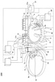
- FIG. 1 is a perspective view of the automatic analyzer of this embodiment.
- the automatic analyzer 1000 is a device for dispensing a sample and a reagent into a reaction vessel 2 and reacting them, and measuring the reacted liquid, which is a reaction disk 1, a reagent disk 9, and a sample.
- Reaction vessels 2 are lined up on the circumference of the reaction disk 1.
- a sample transport mechanism 17 for moving the rack 16 on which the sample container 15 is placed is installed near the reaction disk 1.
- a sample dispensing mechanism 11 that can rotate and move up and down is installed between the reaction disk 1 and the sample transport mechanism 17, and is provided with a sample probe 11a.
- a sample syringe 19 is connected to the sample probe 11a. The sample probe 11a moves while drawing an arc around the axis of rotation to dispense the sample from the sample container 15 to the reaction container 2.
- the reagent disk 9 has a structure in which a plurality of reagent bottles 10 containing reagents can be stored on the circumference. The details will be described later.
- This reagent disc 9 is kept cold and is covered with a cover provided with a suction port 111 (see FIG. 2).
- no device for example, RFID sensor or the like for obtaining information on the reagent in the reagent bottle 10 recorded on the RFID tag attached to the reagent bottle 10 is provided inside the reagent disk 9. It shall not be.
- a reagent dispensing mechanism 7 and 8 that can rotate and move up and down are installed between the reaction disk 1 and the reagent disk 9, and are equipped with reagent probes 7a and 8a, respectively.
- a reagent syringe 18 is connected to the reagent probes 7a and 8a. The reagent probes 7a and 8a move while drawing an arc around the axis of rotation, access the inside of the reagent disk 9 from the suction port 111, and dispense the reagent from the reagent bottle 10 to the reaction vessel 2.
- a cleaning mechanism 3, a light source 4a, a spectrophotometer 4, and stirring mechanisms 5 and 6 are further arranged around the reaction disk 1.
- a cleaning pump 20 is connected to the cleaning mechanism 3.
- Cleaning tanks 32, 33, 13, 30, and 31 are installed within the operating range of the reagent dispensing mechanism 7, 8, the sample dispensing mechanism 11, and the stirring mechanism 5, 6, respectively.
- the sample container 15 contains a sample, is placed on the rack 16, and is carried by the sample transport mechanism 17. Further, each mechanism is connected to the controller 21.
- the controller 21 is composed of a computer or the like, controls the operation of each mechanism in the automatic analyzer 1000, and performs arithmetic processing for obtaining the concentration of a predetermined component in the sample.
- the sample analysis process by the automatic analyzer 1000 as described above is generally executed in the following order.
- the sample in the sample container 15 placed on the rack 16 transported near the reaction disk 1 by the sample transfer mechanism 17 is subjected to the reaction container 2 on the reaction disk 1 by the sample probe 11a of the sample dispensing mechanism 11. Dispense into.
- the reagent used for analysis is dispensed from the reagent bottle 10 on the reagent disk 9 to the reaction vessel 2 into which the sample was previously dispensed by the reagent dispensing mechanisms 7 and 8.
- the stirring mechanism 5 stirs the mixed solution of the sample and the reagent in the reaction vessel 2.
- the light generated from the light source 4a is passed through the reaction vessel 2 containing the mixed solution after stirring, and the luminous intensity of the transmitted light is measured by the spectrophotometer 4.
- the luminous intensity measured by the spectrophotometer 4 is transmitted to the controller 21 via the A / D converter and the interface. Then, a calculation is performed by the controller 21, the concentration of a predetermined component in the sample is obtained, and the result is displayed on the display unit 21a or the like or stored in a storage unit (not shown).
- FIG. 2 is a diagram showing an outline of the autoloader mechanism 100.
- FIG. 3 is a schematic view of the gripper mechanism.
- FIG. 4 is a schematic view showing the relationship between the rib of the reagent disk or the reagent mounting portion and the reagent bottle.
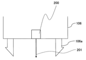
- FIG. 5 is a schematic view of a sensor provided in the gripper mechanism.
- a lid 112 is attached to the position of the reagent probe suction port of the reagent bottle 10 to seal the inside, and when the lid 112 is set in the automatic analyzer 1000, the lid 112 is removed and installed in the device. Is common.
- the autoloader mechanism 100 is arranged on the upper part of the reagent disc 9 and has a configuration as shown in FIG. In FIG. 2, the autoloader mechanism 100 includes a reagent loading unit 103, a reagent loading mechanism 102, a reagent transfer mechanism 101, a needle cleaning tank 108, a needle drying port 109, an RFID sensor 115, a support column 117, and a metal plate 118. Each of these mechanisms except the support column 117 is attached to one metal plate 118.
- the reagent loading unit 103 is a part for the operator to install the reagent bottle 10 when charging the reagent bottle 10 into the automatic analyzer 1000, and the reagent loading unit 103 is vertically oriented on FIG. 2 by the reagent loading mechanism 102. It works on.
- the operating range of the reagent loading unit 103 is set within the apparatus by fixing it on the metal plate 118 on which the autoloader mechanism 100 is arranged.
- the reagent loading unit 103 has a structure in which a plurality of reagent bottles 10 can be installed in a straight line, and is, for example, a tray having a plurality of reagent bottle slots for installing the reagent bottles 10.
- the reagent mounting unit 103 moves on the rail by the power of a motor or the like along a guide installed between the charging position of the reagent bottle 10 into the device and the standby position of the reagent mounting unit 103. It is configured to be able to.
- the reagent transfer mechanism 101 is a mechanism for transporting the reagent bottle 10 installed in the reagent loading unit 103 into the reagent disk 9, or installing the reagent bottle 10 in the reagent disk 9 in the reagent loading unit 103.
- the reagent transfer mechanism 101 includes a gripper mechanism 106 for gripping the reagent bottle 10, a lid opening mechanism 104 for making a notch-shaped hole in the lid 112 of the reagent bottle 10, and a vertical drive motor 132 for moving the lid opening mechanism 104 up and down. Further, the horizontal drive motor 131 for driving the gripper mechanism 106 and the lid opening mechanism 104 in the left-right direction on FIG. 2 is a component.
- the reagent transfer mechanism 101 operates in the left-right direction on FIG. 2 between the position of the reagent mounting portion 103 in FIG. 2 and the position of the opening / closing cover 113. That is, the reagent loading portion 103 moves in the vertical direction on FIG. 2, and the reagent transport mechanism 101 operates in the horizontal direction on FIG. 2, so that the operating directions are orthogonal to each other. Further, in the reagent transport mechanism 101, a position where the reagent bottle 10 is gripped by the gripper mechanism 106 and a position where the reagent bottle 10 is carried in and out of the reagent disk 9 are arranged linearly.
- the lid opening mechanism 104 is provided with a needle 105 for making a notch in the lid 112 of the reagent bottle 10.
- the needle 105 is washed after making a notch in the lid 112 in the needle washing tank 108 arranged parallel to the operating direction of the reagent transporting mechanism 101, and the reagent is transported in the next step.
- the washing water is removed by the needle drying port 109 arranged parallel to the operating direction of the mechanism 101.
- the needle cleaning tank 108 and the needle drying port 109 are arranged parallel to the operating direction of the reagent transport mechanism 101.
- the gripper mechanism 106 has a hooking claw 106a for gripping the reagent bottle 10, and the hooking claw 106a is hooked on the notch portion of the reagent bottle 10 to grip the reagent bottle 10. do.
- the opening / closing cover 113 is a cover for preventing the cold air inside the cooled reagent disk 9 from escaping, and is normally in a closed state.
- the opening / closing cover 113 opens, and operates so that the reagent bottle 10 can be carried in and out of the reagent disc 9.
- the RFID sensor 115 is arranged on the operation path of the reagent mounting unit 103, and obtains the information of the reagent in the reagent bottle 10 recorded on the RFID tag attached to the reagent bottle 10.
- the reagent information is information such as the type and filling amount of the reagent contained in the reagent bottle. Further, instead of the RFID sensor 115, a mechanism capable of reading a bar code and reading reagent information such as a bar code reader can be provided.
- the operator wants to carry the new reagent bottle 10 into the reagent disk 9 of the device, first press the button switch (not shown) of the device for the first time.
- the device recognizes that the first press of the button switch has been performed by the operator.
- the reagent loading mechanism 102 operates, the reagent loading unit 103 starts to move from the standby position, and moves to the front of the device (lower side in FIG. 2).
- the operator After the reagent loading unit 103 arrives in front of the device, the operator installs the reagent bottle 10 in the reagent loading unit 103. After installing the required number of reagent bottles 10 in the reagent loading unit 103, the operator presses the button switch again.
- the reagent information is read by the RFID sensor 115 mounted on the autoloader mechanism 100.
- the reagent information is read, it is displayed on the display unit 21a that the reagent information is provisionally registered.
- the reagent mounting unit 103 moves to the lower position of the lid opening mechanism 104.
- the lid opening mechanism 104 descends toward the lid 112 of the reagent bottle 10, and the needle 105 opens a notch in the lid 112 to the extent that the reagent probes 7a and 8a can be inserted.
- the lid opening mechanism 104 rises, and the reagent transfer mechanism 101 moves to the position of the needle cleaning tank 108 to wash the needle 105, and cleans the needle 105. After that, it moves to the needle drying port 109 and the needle 105 is dried.
- the reagent loading mechanism 102 operates the reagent loading unit 103 to move the notched reagent bottle 10 to the lower position of the gripper mechanism 106. After that, the gripper mechanism 106 is lowered to grab the reagent bottle 10, and then the open / close cover 113 is opened. After that, as the gripper mechanism 106 rises, it moves to the position of the open opening / closing cover 113, and carries in the reagent bottle 10 carried to the position of the empty reagent disk 9. After carrying in, the gripper mechanism 106 is returned to the position of the reagent mounting portion 103 again.
- the opening / closing cover 113 When the opening / closing cover 113 is normally closed, it is recognized that the reagent bottle 10 is normally installed on the reagent disk 9, and the registration of the reagent information is completed. At this time, the display unit 21a attached to the apparatus displays that the reagent information has been fully registered from the provisional registration state.
- the above is the reading of the reagent information from the installation of the reagent bottle 10 in the autoloader mechanism 100, the operation of drilling the lid 112 of the reagent bottle 10, the operation of carrying in the reagent disk 9, and the registration of the reagent information.
- the reagent bottle 10 is carried out according to the following flow.
- the carry-out timing of the reagent bottle 10 may be carried out even during the analysis after the completion of the final dispensing of the reagent dispensing mechanisms 7 and 8 or after the output of the analysis result.
- the controller 21 opens the open / close cover 113. Further, the reagent transfer mechanism 101 moves to the position of the open / close cover 113. Next, the empty reagent bottle 10 is gripped by the gripper mechanism 106. In parallel with this, the reagent loading unit 103 moves from the standby position, and the empty reagent bottle slot of the reagent mounting unit 103 stops at a position below the orbit of the gripper mechanism 106.
- the reagent transfer mechanism 101 moves to the position of the reagent loading mechanism 102 while holding the empty reagent bottle 10 by the gripper mechanism 106. In parallel with this, the opening / closing cover 113 is closed. At that time, it is determined that the reagent bottle 10 has been normally carried out, and the display unit 21a indicates that the registered reagent information has been deleted. After that, the empty reagent bottle 10 is placed in the empty reagent bottle slot of the reagent loading portion 103 by the gripper mechanism 106. After that, the reagent loading mechanism 102 returns to the standby position.
- the display unit 21a or the like notifies the operator that the empty reagent bottle 10 can be taken out.
- the operator Upon receiving this notification, the operator takes out the empty reagent bottle 10 out of the device.
- the reagent disk 9 is used. Provide one or several empty reagent slots for the number that can be installed. Then, the reagent bottle 10 installed in the reagent mounting section 103 is carried into the reagent disk 9 without making a cut in the lid 112, and the empty reagent bottle 10 is grasped by the gripper mechanism 106 and placed on the reagent mounting section 103. After that, the operator carries out the empty reagent bottle 10. After carrying out, the reagent bottle 10 without a notch installed in the reagent disk 9 can be returned to the empty reagent slot again. Similar operation is possible if an empty slot is provided in the reagent mounting portion 103.
- the reagent bottle 10 When the position of the reagent bottle 10 is displaced with respect to the gripper mechanism 106 in the operation of the reagent disk 9 and the reagent mounting portion 103, the reagent bottle 10 is gripped by the gripper mechanism 106 at a position different from the originally gripped portion. There is a pity that stable grip cannot be performed. In addition, when the deviation becomes large, in the worst case, it may not be possible to grasp it.
- the lid 112 is operated to open a notch to the extent that the reagent probes 7a and 8a can be inserted into the lid 112 with the needle 105.
- the notch is opened at a position deviated from the center position of the reagent, and there is a pity that an unnecessary load is applied to the reagent probes 7a and 8a at the time of suction.
- the notch cannot be opened, or the notch is made in an unnecessary part and the contact between the reagent and the outside air becomes large, so that the deterioration of the reagent may progress. There is.
- the reagent disk 9 is provided with a rib 300 for partitioning the reagent bottle 10 on the installation surface 500 of the reagent disk 9, and the reagent mounting portion 103 also partitions the reagent bottle 10 on the installation surface 600.
- Ribs 400 are provided.
- the gap 900 between the ribs 300, 400 and the reagent bottle 10 shown in FIG. 4 is set to 0.5 mm or less in consideration of the above-mentioned risk.
- the gripper mechanism is used when the positional relationship between the reagent disk 9 and the gripper mechanism 106 and the reagent mounting portion 103 and the gripper mechanism 106 is broken.
- the reagent bottle 10 may run on the rib 300. Further, there is a possibility that the reagent bottle 10 rides on the rib 400 in the same operation with respect to the reagent mounting portion 103.
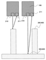
- a sensor (light source 210 + detector 211) is provided in the gripper mechanism 106, and the rib 300 provided in the reagent disk 9 or the reagent mounting portion 103 is provided.
- the idea was to detect the provided rib 400 and automatically adjust the positions of the reagent disk 9 and the gripper mechanism 106 or the reagent mounting portion 103 and the gripper mechanism 106.
- the reference member is not limited to the ribs 300 and 400, and a marker or a concave-convex shape for installing a reagent can be used, and the sensor is not limited to the reflective type, and a camera, a laser displacement meter, or the like can be used.
- the members and sensors that serve as the standard for the above, the idea was that any type other than the originally provided configuration could be used, either a stationary type or a removable type.
- the senor 200 is provided in the gripper mechanism 106 of the reagent transfer mechanism 101.
- the sensor 200 includes a light source 210 and a detector 211, and by using triangulation, the distance from the sensor 200 to the target surface can be grasped.
- the controller 21 adjusts the transfer parameters of the reagent transfer mechanism 101 based on the positions of the ribs 300 and ribs 400 detected by the reflection type sensor 200.
- the sensor 200 may be incorporated in the gripper mechanism 106 or may be removable.
- the removable structure is not particularly limited, and various known means can be adopted. This makes it very easy to apply the technique of the present invention to an existing device.
- the senor 200 is performed on the assumption that the optical axis 201 is located at the center of the gripper mechanism 106.
- the senor 200 may be located anywhere in the gripper mechanism 106, but in that case, it is necessary to further reflect the distance from the optical axis 201 of the sensor 200 to the center of the gripper mechanism 106 as a correction value in the following description. be.
- FIG. 6 is a schematic view showing the ribs of the reagent disk and the reagent mounting portion.
- FIG. 7 is a schematic view showing a cross-sectional view of the reagent disk and the gripper mechanism in the X direction, and
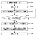
- FIG. 8 is a flowchart for automatically adjusting the position of the gripper mechanism (X direction) with respect to the reagent disk.
- FIG. 9 is a schematic view showing a cross-sectional view of the reagent disk and the gripper mechanism in the Y direction, and FIG.
- FIG. 10 is a flowchart for automatically adjusting the position of the reagent disk (in the ⁇ direction) with respect to the gripper mechanism.
- FIG. 11 is a schematic view showing a cross-sectional view of the reagent disk and the gripper mechanism in the Z direction
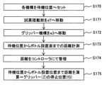
- FIG. 12 is a flowchart for automatically adjusting the position of the gripper mechanism (Z direction) with respect to the reagent disk.
- each configuration on the installation surface 500 of the reagent disk 9 and the installation surface 600 of the reagent mounting portion 103 will be described with reference to FIG.
- a plurality of reagent bottles 10 can be placed concentrically, and ribs 300a and 300b for setting installation positions from the inner peripheral side to the inner peripheral side in the radial direction.
- ribs 300c and 300d for setting the installation position on the outer peripheral side are provided.
- ribs 300e and 300f are provided on the inner peripheral side
- ribs 300g and 300h are provided on the outer peripheral side, respectively.
- the installation position on the outer peripheral side is set by 300c, 300g, 300d, and 300h.
- the reagent mounting unit 103 is configured so that five reagent bottles 10 can be mounted in FIG. 6, and ribs 400a, 400b, 400c, 400d, and 400e are provided from the lower middle side of FIG. A wall having a height higher than that of the rib is provided on the back side of the rib 400e. Ribs 400f and 400g are provided on the side surface sides of these ribs 400a, 400b, 400c, 400d and 400e.
- the moving direction of the reagent mounting portion 103 is the X direction
- the moving direction of the gripper mechanism 106 is the Y direction
- the vertical direction of the paper surface of FIG. 6 is the Z direction.
- the direction of the rotation component on the XY plane is the ⁇ direction.
- step S120 the reagent disc 9 and the gripper mechanism 106 are moved to the standby position to start the operation.
- step S121 open the open / close cover 113
- step S121 open the open / close cover 113
- step S121 open the open / close cover 113
- the gripper mechanism 106 is operated in the direction of the opening / closing cover 113.
- the horizontal drive motor 131 of the gripper mechanism 106 is a stepping motor
- the horizontal drive motor 131 is driven by one pulse (step S122), and after the movement, the sensor 200 is used to confirm the presence / absence of detection of the rib 300a. (Step S123).
- step S122 If it is not detected, the process is returned to step S122, and the horizontal drive motor 131 is driven by one pulse again.
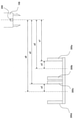
- the distance a1 from the standby position of the gripper mechanism 106 to the rib 300a is grasped and managed from the total number of pulses given when the controller 21 is detected (step S124).
- the drive motor When the drive motor is equipped with an encoder capable of grasping the rotation speed and the position, it is possible to grasp the above-mentioned distances a1 and a2 by operating the drive motor at a constant speed. Compared to stepping motors, it is possible to shorten the time required to grasp each distance.
- the center position between the rib 300a and the rib 300b and the center position a3 between the rib 300c and the rib 300d which are the installation positions of the reagent bottle 10, are fixed values and can be grasped from the processes of steps S120 to S124.
- the distance a5 obtained by adding the distance a3 to the distance a1 and the distance a6 obtained by adding the distance a3 to the distance a2 are the stop positions of the gripper mechanism 106 with respect to the reagent disk 9. Therefore, the controller 21 sets the stop positions a5 and a6 in the X direction with respect to the reagent disk 9 of the gripper mechanism 106 (step S125), and closes the open / close cover 113 (step S126).
- step S130 Immediately after the adjustment of the stop positions a5 and a6 described above is completed, or after a predetermined time has elapsed, the controller 21 again puts the reagent disk 9 and the gripper mechanism 106 into the standby position as shown in FIGS. 9 and 10. Move (step S130).
- step S131 the open / close cover 113 is opened (step S131).
- the gripper mechanism 106 is moved to the reagent bottle 10 installation position a5 on the inner peripheral side of the reagent disc 9 (step S132).
- the position to be moved at this time is the one set in step S125.
- the reagent disk drive motor (not shown) is driven by one pulse (step S133), and after rotation, the presence or absence of detection of the rib 300e is confirmed using the sensor 200 (step S134).
- the reagent disk 9 and the reagent disk drive motor are connected by a gear or a belt, but in consideration of backlash in the gear or the belt, the rotation direction of the reagent disk 9 and the reagent disk drive motor described above is the reagent disk. 9 and the direction of movement of the reagent disk drive motor to the standby position are the same.
- step S133 If the sensor 200 does not detect it, the process is returned to step S133, and the reagent disk drive motor is driven by one pulse.
- the distance b1 from the standby position of the reagent disk 9 to the rib 300e is grasped and managed from the total number of pulses given at the time of detection (step S135).
- steps S131 to S135 By applying the operations of steps S131 to S135 to the reagent bottle 10 installation position a6 on the outer peripheral side of the reagent disk 9, it is possible to grasp the distance b2 from the standby position of the reagent disk 9 to the rib 300 g.
- the drive motor When the drive motor is equipped with an encoder capable of grasping the rotation speed and the position, it is possible to grasp the above-mentioned distances b1 and b2 by operating the drive motor at a constant speed. Compared to stepping motors, it is possible to shorten the time required to grasp each distance.
- the center positions b3 between the ribs 300e and 300f and the center positions b3 between the ribs 300g and 300h, which are the installation positions of the reagent bottle 10, are fixed values.
- the distance b5 obtained by subtracting the distance b3 from the distance b1 and the distance b6 obtained by subtracting the distance b3 from the distance b2 are the stop positions of the reagent disk 9 with respect to the gripper mechanism 106. Therefore, the controller 21 sets the stop positions b5 and b6 in the ⁇ direction with respect to the reagent disk 9 of the gripper mechanism 106 (step S136). After that, the opening / closing cover 113 is closed (step S137).
- step S140 the reagent disc 9 and the gripper mechanism 106 are moved to the standby position, and the operation is started (step S140).
- step S141 the open / close cover 113 is opened (step S141).
- the gripper mechanism 106 is moved to the stop position a5 set in step S125 described above (step S142), and the reagent disk 9 is horizontally moved to the stop position b5 set in step S136 described above (step). S143).
- the stop position of the gripper mechanism 106 may be a6, and the stop position of the reagent disc 9 may be b6.
- step S144 the distance c1 from the standby position of the gripper mechanism 106 in the vertical direction to the reagent bottle installation surface 500 of the reagent disk 9 is grasped.
- the grasped distance is managed by the controller 21 (step S145).
- c2 is defined as the height obtained by adding the height of the reagent bottle 10 and the cushioning amount of the gripper mechanism 106 required for hooking the hooking claw 106a to the notch portion of the reagent bottle 10.
- the height c3 of the gripper mechanism 106 when installing the reagent bottle 10 on the disk 9 and when gripping the reagent bottle 10 from the reagent disk 9 is a value obtained by subtracting c2 from the distance c1 acquired from the above sensor, and c3 is the gripper mechanism.
- This is the stop position of 106 in the vertical direction. Therefore, the controller 21 sets the stop position c3 of the gripper mechanism 106 in the Z direction (step S146). After that, the opening / closing cover 113 is closed (step S147).
- FIG. 13 is a schematic view showing a cross-sectional view of the reagent mounting portion and the gripper mechanism in the Y direction
- FIG. 14 is a flowchart for automatically adjusting the position of the reagent mounting portion (Y direction) with respect to the gripper mechanism.
- FIG. 15 is a schematic view showing a cross-sectional view of the reagent mounting portion and the gripper mechanism in the X direction
- FIG. 16 is a flowchart for automatically adjusting the position of the gripper mechanism (X direction) with respect to the reagent mounting portion.
- FIG. 17 is a schematic view showing a cross-sectional view of the reagent mounting portion and the gripper mechanism in the Z direction
- FIG. 18 is a flowchart for automatically adjusting the position of the gripper mechanism (Z direction) with respect to the reagent mounting portion.
- step S150 the reagent mounting portion 103 and the gripper mechanism 106 are moved to the standby position, and the operation is started (step S150).
- the gripper mechanism 106 is operated in the direction of the opening / closing cover 113 and stopped on the orbit of the reagent mounting portion 103 (step S151).
- the stop position of the gripper mechanism 106 is a temporary position where the adjustment value is not reflected.
- step S152 when the drive motor 134 of the reagent mounting unit 103 is a stepping motor, the drive motor 134 is driven by one pulse to move the reagent mounting unit 103 toward the device (step S152), and after the movement, the sensor 200 is used. , Confirm the presence / absence of detection of the rib 400a (step S153).
- step S152 If the sensor 200 does not detect it, the process returns to step S152 and the drive motor 134 is driven by one pulse.
- the controller 21 grasps and manages the distance d1 from the standby position of the reagent mounting unit 103 to the rib 400a from the total number of pulses given at the time of detection (step S154).
- the drive motor When the drive motor is equipped with an encoder capable of grasping the rotation speed and the position, it is possible to grasp the above-mentioned distances d1 to d5 by operating the drive motor at a constant speed. Compared to stepping motors, it is possible to shorten the time required to grasp each distance.
- the center distance d6 between the rib 400a and the rib 400b which is the installation position of the reagent bottle 10, is a fixed value.
- the distance d7 obtained by adding the distance d6 to the distance d1 grasped from the above-mentioned operation is the stop position of the reagent mounting position of the reagent mounting unit 103 with respect to the gripper mechanism 106. Therefore, the controller 21 sets the stop position d7 in the Y direction of the reagent mounting unit 103 (step S155).
- step S160 After the adjustment of the stop position of the reagent mounting unit 103 in the Y direction is completed, the reagent mounting unit 103 and the gripper mechanism 106 are moved to the standby position as shown in FIGS. 15 and 16 (step S160).
- step S161 the reagent mounting position of the reagent loading unit 103 is moved to the above-mentioned stop position d7 (step S161).
- step S162 the horizontal drive motor 131 of the gripper mechanism 106 is driven by one pulse to move the gripper mechanism 106 toward the open / close cover 113 (step S162).
- step S163 After moving, the presence or absence of detection of the rib 400f is confirmed using the sensor 200 (step S163).
- step S162 If the sensor 200 does not detect it, the process returns to step S162 and the horizontal drive motor 131 is driven by one pulse.
- the controller 21 grasps and manages the distance e1 from the standby position of the gripper mechanism 106 to the rib 400f from the total number of pulses given at the time of detection (step S164).
- the drive motor When the drive motor is equipped with an encoder capable of grasping the rotation speed and the position, the distance e1 can be grasped by operating the drive motor at a constant speed, and the stepping motor can be grasped. It is possible to shorten the time required to grasp each distance.
- the center distance e2 between the rib 400f and 400 g which is the installation position of the reagent bottle 10, is a fixed value.
- the distance e3 obtained by adding the distance e2 to the distance e1 grasped from the above-mentioned operation is the stop position of the gripper mechanism 106 with respect to the reagent mounting portion 103. Therefore, the controller 21 defines the stop position e3 in the X direction with respect to the reagent mounting portion 103 of the gripper mechanism 106 (step S165).
- step S170 the reagent mounting portion 103 and the gripper mechanism 106 are moved to the standby position, and the operation is started (step S170).
- the reagent mounting unit 103 is moved to the stop position d7 set in step S155 described above (step S171), and the gripper mechanism 106 is horizontally moved to the stop position e3 set in step S165 described above (step). S172).
- step S173 the distance f1 from the standby position of the gripper mechanism 106 in the vertical direction to the reagent bottle mounting surface 600 of the reagent mounting unit 103 is grasped.
- the grasped distance is managed by the controller 21 (step S174).
- f2 is defined as the height obtained by adding the height of the reagent bottle 10 and the cushioning amount of the gripper mechanism 106 required for hooking the hooking claw 106a to the notch of the reagent bottle 10
- the height f3 of the gripper mechanism 106 when the reagent bottle 10 is installed on the mounting unit 103 and when the reagent bottle 10 is gripped from the reagent mounting unit 103 is a value obtained by subtracting f2 from the distance f1 acquired from the above sensor, and f3 is This is the stop position of the gripper mechanism 106 in the vertical direction. Therefore, the controller 21 sets the stop position f3 in the Z direction of the gripper mechanism 106 (step S175).
- the lid 112 attached to the reagent bottle 10, the needle cleaning tank 108, and the needle drying port 109 may be provided with a taper. Further, the needle 105 may also be provided with a taper.
- the horizontal direction of the needle cleaning tank 108 and the needle drying port 109 is not essential, but may be performed.
- the needle 105 may be provided with a cushioning material. Therefore, even if some misalignment of the lid 112, the needle cleaning tank 108, and the needle drying port 109 with respect to the needle 105 occurs in the vertical direction, it can be corrected.
- the position adjustment of the mechanism 104 is not essential, but may be performed.
- FIG. 19 is a schematic view showing a cross-sectional view of the reagent disk and the gripper mechanism in the Z direction
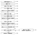
- FIG. 20 is a flowchart showing an operation of confirming the height and inclination of the reagent bottle mounting surface 500 of the reagent disk using the gripper mechanism. be.
- the reagent disc 9 also has the problems described below.
- the reagent disc 9 is generally manufactured by integral molding or by dividing parts, but since it has a large shape and the support point is only the center of rotation of the reagent disc 9, it is subject to gravity. As a result, it is conceivable that the reagent bottle installation surface of the reagent disk 9 will be distorted.
- Distortion of the reagent bottle mounting surface 500 of the reagent disk 9 shown in FIG. 19 may affect the reagent dispensing performance of the reagent probes 7a and 8a.
- the reagent probes 7a and 8a move while drawing an arc around the rotation axis, access the inside of the reagent disk 9 from the suction port 111, and dispense the reagent from the reagent bottle 10 to the reaction vessel 2. conduct.
- the distortion of the reagent disk 9 causes a variation in the height of each reagent bottle mounting surface 500, and even if the same reagent bottle 10 is used, the liquid level of each reagent bottle 10 as seen from the reagent probes 7a and 8a There is a difference in height, which may affect the reagent dispensing performance. Further, if the reagent bottle installation surface 500 is tilted, the reagent probes 7a and 8a cannot be inserted into the notch of the lid 112, which may lead to bending of the probe and stoppage of the device.
- the reagent disc 9 and the gripper mechanism 106 are moved to the standby position, and the adjustment is started (step S180).
- step S181 the open / close cover 113 is opened (step S181).
- the reagent disc 9 is moved to b5 (step S182), and the gripper mechanism 106 is moved to a7 (step S183).
- the sensor 200 is used to grasp the distance g1 from the gripper mechanism 106 to the reagent bottle installation surface 500 (step S184).
- the reagent disk 9 is moved from b5 to the position b7 (omitted for convenience of illustration) rotated by a very small amount (for example, one step) (step S185), and the gripper mechanism 106 is moved to a8 (step S186). ..
- the sensor 200 is used to grasp the distance g2 from the gripper mechanism 106 to the reagent bottle installation surface 500 (step S187).
- the reagent disk 9 is moved from b5 to the position b8 (omitted for convenience of illustration) rotated by a very small amount (for example, -1 step) (step S188).
- the sensor 200 is used to grasp the distance g3 from the gripper mechanism 106 to the reagent bottle installation surface 500 (step S189).
- the distances grasped in steps S184, S187, and S189 are managed by the controller 21, and the open / close cover 113 is closed (step S190).
- the reagent disk 9 does not have the reagent bottle 10 for the above-mentioned operation.
- the range is narrowed down to a place where the reagent bottle 10 is not installed, and the reagent bottle installation surface. It is possible to detect whether there is any abnormality in the height and inclination of the.
- the height and inclination of the reagent bottle installation surface 500 are grasped, and it is determined whether or not there is an abnormality in the height and inclination of the reagent bottle installation surface 500 (step). S191). For example, it is determined based on conditions such as whether or not the differences between the distances g1, g2, and g3 are all less than a predetermined value.
- step S192 when it is determined that there is no abnormality, the reagent bottle installation surface 500 is left usable (step S192), and the process is terminated.
- the data such as the horizontal position, the vertical position, and the height and inclination of the reagent bottle mounting surface of the reagent disk 9 with respect to the gripper mechanism 106 of the reagent transfer mechanism 101 with respect to the reagent disk 9 or the reagent mounting unit 103 obtained from the above are obtained from the controller 21. Manage at.
- the controller 21 determines whether or not there is an abnormality or a failure state of the reagent loading unit 103, the reagent disk 9, or the reagent transport mechanism 101 from the acquired data of the change with time of the distance, and when the controller 21 deviates from the reference range. If an abnormality is found, such as exceeding the threshold value, an alarm is issued.
- controller 21 predicts the time when the reagent loading unit 103, the reagent disk 9, or the reagent transport mechanism 101 is determined to be in an abnormal or failed state based on the change over time, and issues an alarm. can.
- the stop position of the reagent mounting unit 103, the reagent disk 9, and the reagent transfer mechanism 101 is expected to change due to deterioration over time, so the life of each component is predicted from the transition of the acquired position data. And an alarm can be issued.
- the device can be used as usual.
- an alarm is set to recommend replacement of the corresponding part, and the device can be used as usual.
- an alarm is set to stop the registration and deletion function of the reagent, and the function of the autoloader mechanism 100 is stopped.
- the controller 21 stops only the operation of the reagent transfer mechanism 101, and an alarm indicating that the transfer of the reagent bottle 10 by the reagent transfer mechanism 101 is stopped. Can be triggered. At this time, the other mechanisms can be operated as usual, and analysis is possible as long as the amount of the reagent in the installed reagent bottle 10 is not exhausted.
- the check function of each mechanism described above is an example, but by providing the check function described above, it is possible to detect an abnormality in the device and prevent an abnormal state such as a device stop during analysis.
- the reagent bottle 10 is basically installed only at the time of loading and unloading, no special consideration is required as compared with the reagent disk 9.
- the rib 300 provided on the reagent disk 9, the rib 400 provided on the reagent mounting portion 103, and the rib 300 provided on the reagent transport mechanism 101 Since it is provided with a reflection type sensor 200 for detecting 400 and a controller 21 for adjusting the transfer parameters of the reagent transfer mechanism 101 based on the positions of the ribs 300 and 400 detected by the reflection type sensor 200. It is possible to automatically grasp the relative positional relationship (horizontal / height) between the reagent disk 9 and the mechanism related to the loading / unloading of the reagent bottle on the device side, and reflect the adjustment value to each mechanism unit.
- the reagent bottle 10 can be normally installed on the reagent disc 9 more stably than in the conventional case.
- the reflection type sensor 200 can adjust the horizontal movement parameter of the reagent transfer mechanism 101 by measuring the distance from the standby position in the horizontal direction of the reagent transfer mechanism 101 to the ribs 300 and 400.
- the horizontal movement amount of the reagent transfer mechanism 101 based on the distance from the standby position to the ribs 300 and 400, the horizontal movement of the reagent transfer mechanism 101 without performing manual maintenance or the like is performed.
- the distance can be adjusted, and stable reagent bottle 10 can be transported.
- the reflection type sensor 200 can adjust the movement parameter of the reagent transfer mechanism 101 in the vertical direction by measuring the distance from the standby position of the reagent transfer mechanism 101 in the vertical direction to the ribs 300 and 400.
- the vertical movement of the reagent transfer mechanism 101 can be performed without performing manual maintenance or the like.
- the distance can be adjusted, and stable reagent bottle 10 can be transported.
- the position shift due to deterioration over time can be automatically grasped, and measures such as reflecting the shift amount in the adjustment value can be taken before a malfunction such as a failure occurs. Therefore, it is possible to suppress the abnormal stoppage of the device during the analysis as compared with the conventional case.
- the reagent loading unit 103, the reagent disk 9, or the reagent transport mechanism 101 is determined to be in an abnormal or failed state based on the change over time, and issuing an alarm, a failure or the like can be detected earlier. You can take measures before a problem occurs.
- the height and inclination of the installation surface 500 are obtained from the time course of the distance from the standby position to the rib 300 at a plurality of places, and the abnormality or failure state of the reagent disk 9 is determined from the inclination, so that the reagent disk 9 itself It is possible to automatically determine the presence or absence of aging deterioration.
- the reagent disk 9 itself becomes unusable by issuing an alarm by predicting the time when the reagent disk 9 is determined to be in an abnormal or failed state from the change over time. It will be easier to suppress than before.
- the reagent bottle 10 to the reagent discs 9 other than the reagent discs 9 determined to have an abnormality is added.
- the analysis is completely stopped only because the reagent disk 9 having an abnormality exists. It can be suppressed.
- an automatic analyzer provided with an autoloader mechanism 100 for automatically carrying the reagent bottle 10 into the reagent disk 9 has been described as an example, but the autoloader mechanism 100 is not necessarily in the form shown in FIG. It is not necessary to have the present invention, and the present invention can be applied as long as it has at least one location where the drive shafts intersect.
- the reagent disk 9 or the reagent mounting unit 103 is not the gripper mechanism 106 but the reagent disk 9 or the reagent mounting unit 103.
- a sensor 200 is provided on the side, and the transfer parameters of the reagent transfer mechanism 101 can be controlled based on the position of the reference member provided in the reagent transfer mechanism 101. Even in such an embodiment, the same effect as that of the above-described embodiment can be obtained.
- the reference member is the ribs 300 and 400 for partitioning the reagent bottle 10
- a marker provided on the reagent transfer mechanism 101, the reagent disk 9, or the reagent mounting portion 103 is described.
- at least one of the concave shape and the convex shape indicating the position where the reagent bottle 10 is installed can be used as the reference member, and the same effect can be obtained.
- the reference member is a marker, it can be made removable. If it is removable in this way, the present invention can be easily applied to existing devices, and it is only necessary to attach it when adjustment is required, so that it may interfere with the operation during normal analysis operation. It can be assumed that there is almost no sex.
- the reflection type sensor 200 in which the sensor is composed of the light source 210 and the detector 211 that detects the light emitted from the light source 210 and reflected by the reference member has been described.
- the sensor is a reflection type sensor 200. Instead, it can be at least one of a camera that captures an image of the reference member and a laser displacement meter that measures the distance to the reference member.
- Reagent transfer mechanism (reagent transfer unit) 102 ... Reagent mounting mechanism 103 ... Reagent mounting part 104 ... Lid opening mechanism 105 ... Needle 106 ... Gripper mechanism 106a ... Hooking claw 108 ... Needle cleaning tank 109 ... Needle drying port 111 ... Suction port 112 ... Lid 113 ... Opening / closing cover 115 ... RFID sensor 117 ... Support 118 ... Metal plate 131 ... Horizontal drive motor 132 ... Vertical drive motor 134 ... Drive motor 200 ... Sensor 201 ... Optical axis 210 ... Light source 211 ... Detector 300, 300a, 300b, 300c, 300d, 300e, 300f , 300g, 300hi ...
- Rib (reagent disc) 400, 400a, 400b, 400c, 400d, 400e, 400f, 400g ... Rib (reagent mounting part) 500 ... Reagent bottle installation surface (reagent disc) 600 . Reagent bottle installation surface (reagent mounting part) 900 ... Gap between rib and reagent bottle 1000 ... Automatic analyzer
Landscapes
- Chemical & Material Sciences (AREA)
- Health & Medical Sciences (AREA)
- Immunology (AREA)
- Pathology (AREA)
- Analytical Chemistry (AREA)
- Biochemistry (AREA)
- General Health & Medical Sciences (AREA)
- General Physics & Mathematics (AREA)
- Physics & Mathematics (AREA)
- Life Sciences & Earth Sciences (AREA)
- Engineering & Computer Science (AREA)
- Quality & Reliability (AREA)
- Medicinal Chemistry (AREA)
- Clinical Laboratory Science (AREA)
- Chemical Kinetics & Catalysis (AREA)
- Automatic Analysis And Handling Materials Therefor (AREA)
Abstract
Priority Applications (4)
| Application Number | Priority Date | Filing Date | Title |
|---|---|---|---|
| JP2022550334A JP7433459B2 (ja) | 2020-09-17 | 2021-03-08 | 自動分析装置 |
| CN202180056785.2A CN116034277B (zh) | 2020-09-17 | 2021-03-08 | 自动分析装置 |
| US18/020,197 US20230324426A1 (en) | 2020-09-17 | 2021-03-08 | Automatic Analyzer |
| EP21868919.8A EP4215921B1 (fr) | 2020-09-17 | 2021-03-08 | Dispositif d'analyse automatique |
Applications Claiming Priority (2)
| Application Number | Priority Date | Filing Date | Title |
|---|---|---|---|
| JP2020156008 | 2020-09-17 | ||
| JP2020-156008 | 2020-09-17 |
Publications (1)
| Publication Number | Publication Date |
|---|---|
| WO2022059231A1 true WO2022059231A1 (fr) | 2022-03-24 |
Family
ID=80776796
Family Applications (1)
| Application Number | Title | Priority Date | Filing Date |
|---|---|---|---|
| PCT/JP2021/009030 Ceased WO2022059231A1 (fr) | 2020-09-17 | 2021-03-08 | Dispositif d'analyse automatique |
Country Status (5)
| Country | Link |
|---|---|
| US (1) | US20230324426A1 (fr) |
| EP (1) | EP4215921B1 (fr) |
| JP (1) | JP7433459B2 (fr) |
| CN (1) | CN116034277B (fr) |
| WO (1) | WO2022059231A1 (fr) |
Families Citing this family (1)
| Publication number | Priority date | Publication date | Assignee | Title |
|---|---|---|---|---|
| CN119023987B (zh) * | 2024-10-29 | 2024-12-17 | 西安交通大学医学院第一附属医院 | 妇科分泌物自动检测设备 |
Citations (7)
| Publication number | Priority date | Publication date | Assignee | Title |
|---|---|---|---|---|
| JPS55140154A (en) * | 1979-04-19 | 1980-11-01 | Olympus Optical Co Ltd | Reagent distribution device |
| JPH0510948A (ja) * | 1991-07-08 | 1993-01-19 | Omron Corp | 自動尿検査装置 |
| JP2005037171A (ja) | 2003-07-17 | 2005-02-10 | Hitachi High-Technologies Corp | 自動分析装置 |
| JP2006308560A (ja) * | 2005-03-28 | 2006-11-09 | Sysmex Corp | 搬送装置および搬送システム |
| JP2014095709A (ja) * | 2012-11-12 | 2014-05-22 | Siemens Healthcare Diagnostics Products Gmbh | 自動分析装置用試薬ステーション |
| JP2015517675A (ja) * | 2012-05-24 | 2015-06-22 | シーメンス・ヘルスケア・ダイアグノスティックス・インコーポレーテッドSiemens Healthcare Diagnostics Inc. | 知能オートメーションパック用非接触光エンコーディングスキーム |
| WO2019031451A1 (fr) * | 2017-08-09 | 2019-02-14 | 株式会社日立ハイテクノロジーズ | Appareil d'analyse automatisé |
Family Cites Families (7)
| Publication number | Priority date | Publication date | Assignee | Title |
|---|---|---|---|---|
| JP3192766B2 (ja) * | 1992-08-31 | 2001-07-30 | 株式会社東芝 | マニピュレータ |
| JP2001278409A (ja) * | 2000-03-31 | 2001-10-10 | Nippon Shooter Ltd | 検体搬送車およびこれを用いた検体搬送システム |
| US6846455B1 (en) * | 2001-01-26 | 2005-01-25 | Ta Instruments-Waters, Llc | Automatic sampling device |
| WO2016143478A1 (fr) * | 2015-03-10 | 2016-09-15 | 株式会社日立ハイテクノロジーズ | Dispositif d'analyse automatisé |
| CN108291919B (zh) * | 2015-08-28 | 2021-09-14 | 株式会社日立高新技术 | 自动分析装置及试剂瓶的搬入方法 |
| JP6886837B2 (ja) | 2017-02-22 | 2021-06-16 | 株式会社日立ハイテク | 自動分析装置 |
| JP6865887B2 (ja) * | 2018-02-28 | 2021-04-28 | 株式会社日立ハイテク | 自動分析装置 |
-
2021
- 2021-03-08 WO PCT/JP2021/009030 patent/WO2022059231A1/fr not_active Ceased
- 2021-03-08 EP EP21868919.8A patent/EP4215921B1/fr active Active
- 2021-03-08 US US18/020,197 patent/US20230324426A1/en active Pending
- 2021-03-08 JP JP2022550334A patent/JP7433459B2/ja active Active
- 2021-03-08 CN CN202180056785.2A patent/CN116034277B/zh active Active
Patent Citations (7)
| Publication number | Priority date | Publication date | Assignee | Title |
|---|---|---|---|---|
| JPS55140154A (en) * | 1979-04-19 | 1980-11-01 | Olympus Optical Co Ltd | Reagent distribution device |
| JPH0510948A (ja) * | 1991-07-08 | 1993-01-19 | Omron Corp | 自動尿検査装置 |
| JP2005037171A (ja) | 2003-07-17 | 2005-02-10 | Hitachi High-Technologies Corp | 自動分析装置 |
| JP2006308560A (ja) * | 2005-03-28 | 2006-11-09 | Sysmex Corp | 搬送装置および搬送システム |
| JP2015517675A (ja) * | 2012-05-24 | 2015-06-22 | シーメンス・ヘルスケア・ダイアグノスティックス・インコーポレーテッドSiemens Healthcare Diagnostics Inc. | 知能オートメーションパック用非接触光エンコーディングスキーム |
| JP2014095709A (ja) * | 2012-11-12 | 2014-05-22 | Siemens Healthcare Diagnostics Products Gmbh | 自動分析装置用試薬ステーション |
| WO2019031451A1 (fr) * | 2017-08-09 | 2019-02-14 | 株式会社日立ハイテクノロジーズ | Appareil d'analyse automatisé |
Non-Patent Citations (1)
| Title |
|---|
| See also references of EP4215921A4 |
Also Published As
| Publication number | Publication date |
|---|---|
| CN116034277B (zh) | 2026-01-02 |
| EP4215921A4 (fr) | 2024-11-13 |
| JP7433459B2 (ja) | 2024-02-19 |
| US20230324426A1 (en) | 2023-10-12 |
| EP4215921A1 (fr) | 2023-07-26 |
| CN116034277A (zh) | 2023-04-28 |
| JPWO2022059231A1 (fr) | 2022-03-24 |
| EP4215921B1 (fr) | 2026-02-11 |
Similar Documents
| Publication | Publication Date | Title |
|---|---|---|
| JP6602367B2 (ja) | 自動分析装置 | |
| AU644278B2 (en) | Incubator port closure for automated assay system | |
| JP5178830B2 (ja) | 自動分析装置 | |
| JP2018077230A (ja) | 自動分析装置 | |
| JP6886837B2 (ja) | 自動分析装置 | |
| CN113785205B (zh) | 自动分析装置 | |
| JP7080391B2 (ja) | 自動分析装置 | |
| WO2018155300A1 (fr) | Dispositif d'analyse automatique et mécanisme de nettoyage dans un dispositif d'analyse automatique | |
| WO2022176556A1 (fr) | Dispositif d'analyse automatique et procédé d'aspiration d'échantillon dans un dispositif d'analyse automatique | |
| EP3171180B1 (fr) | Dispositif d'analyse automatique | |
| WO2022059231A1 (fr) | Dispositif d'analyse automatique | |
| JP2010091469A (ja) | 検体分注装置、検体分注方法及び分析装置 | |
| JP5839987B2 (ja) | 自動分析装置 | |
| US20190369130A1 (en) | Automatic Analyzer | |
| JP2815433B2 (ja) | 自動分析装置 | |
| JP4110082B2 (ja) | 自動分析装置 | |
| JP2018138908A (ja) | 自動分析装置 | |
| JP2007322394A (ja) | 分注装置および自動分析装置 | |
| JP2025144280A (ja) | 自動分析装置 | |
| WO2024252820A1 (fr) | Dispositif d'analyse automatique | |
| WO2024190021A1 (fr) | Dispositif de préhension et dispositif d'analyse automatique | |
| CN120507531A (zh) | 试剂容器以及自动分析装置 | |
| WO2022070459A1 (fr) | Analyseur automatisé | |
| JP2018146255A (ja) | 自動分析装置 |
Legal Events
| Date | Code | Title | Description |
|---|---|---|---|
| 121 | Ep: the epo has been informed by wipo that ep was designated in this application |
Ref document number: 21868919 Country of ref document: EP Kind code of ref document: A1 |
|
| ENP | Entry into the national phase |
Ref document number: 2022550334 Country of ref document: JP Kind code of ref document: A |
|
| NENP | Non-entry into the national phase |
Ref country code: DE |
|
| ENP | Entry into the national phase |
Ref document number: 2021868919 Country of ref document: EP Effective date: 20230417 |
|
| WWG | Wipo information: grant in national office |
Ref document number: 2021868919 Country of ref document: EP |