WO2022071432A1 - Appareil d'éclairage pour véhicule - Google Patents
Appareil d'éclairage pour véhicule Download PDFInfo
- Publication number
- WO2022071432A1 WO2022071432A1 PCT/JP2021/035962 JP2021035962W WO2022071432A1 WO 2022071432 A1 WO2022071432 A1 WO 2022071432A1 JP 2021035962 W JP2021035962 W JP 2021035962W WO 2022071432 A1 WO2022071432 A1 WO 2022071432A1
- Authority
- WO
- WIPO (PCT)
- Prior art keywords
- heat
- light source
- fin
- socket
- heat radiating
- Prior art date
- Legal status (The legal status is an assumption and is not a legal conclusion. Google has not performed a legal analysis and makes no representation as to the accuracy of the status listed.)
- Ceased
Links
Images




Classifications
-
- F—MECHANICAL ENGINEERING; LIGHTING; HEATING; WEAPONS; BLASTING
- F21—LIGHTING
- F21S—NON-PORTABLE LIGHTING DEVICES; SYSTEMS THEREOF; VEHICLE LIGHTING DEVICES SPECIALLY ADAPTED FOR VEHICLE EXTERIORS
- F21S45/00—Arrangements within vehicle lighting devices specially adapted for vehicle exteriors, for purposes other than emission or distribution of light
- F21S45/40—Cooling of lighting devices
- F21S45/47—Passive cooling, e.g. using fins, thermal conductive elements or openings
- F21S45/48—Passive cooling, e.g. using fins, thermal conductive elements or openings with means for conducting heat from the inside to the outside of the lighting devices, e.g. with fins on the outer surface of the lighting device
-
- F—MECHANICAL ENGINEERING; LIGHTING; HEATING; WEAPONS; BLASTING
- F21—LIGHTING
- F21S—NON-PORTABLE LIGHTING DEVICES; SYSTEMS THEREOF; VEHICLE LIGHTING DEVICES SPECIALLY ADAPTED FOR VEHICLE EXTERIORS
- F21S41/00—Illuminating devices specially adapted for vehicle exteriors, e.g. headlamps
- F21S41/10—Illuminating devices specially adapted for vehicle exteriors, e.g. headlamps characterised by the light source
- F21S41/14—Illuminating devices specially adapted for vehicle exteriors, e.g. headlamps characterised by the light source characterised by the type of light source
- F21S41/141—Light emitting diodes [LED]
- F21S41/143—Light emitting diodes [LED] the main emission direction of the LED being parallel to the optical axis of the illuminating device
-
- F—MECHANICAL ENGINEERING; LIGHTING; HEATING; WEAPONS; BLASTING
- F21—LIGHTING
- F21S—NON-PORTABLE LIGHTING DEVICES; SYSTEMS THEREOF; VEHICLE LIGHTING DEVICES SPECIALLY ADAPTED FOR VEHICLE EXTERIORS
- F21S41/00—Illuminating devices specially adapted for vehicle exteriors, e.g. headlamps
- F21S41/10—Illuminating devices specially adapted for vehicle exteriors, e.g. headlamps characterised by the light source
- F21S41/19—Attachment of light sources or lamp holders
- F21S41/192—Details of lamp holders, terminals or connectors
-
- F—MECHANICAL ENGINEERING; LIGHTING; HEATING; WEAPONS; BLASTING
- F21—LIGHTING
- F21S—NON-PORTABLE LIGHTING DEVICES; SYSTEMS THEREOF; VEHICLE LIGHTING DEVICES SPECIALLY ADAPTED FOR VEHICLE EXTERIORS
- F21S45/00—Arrangements within vehicle lighting devices specially adapted for vehicle exteriors, for purposes other than emission or distribution of light
- F21S45/40—Cooling of lighting devices
- F21S45/49—Attachment of the cooling means
Definitions
- This disclosure relates to vehicle lighting equipment.
- Vehicle lamps are required to use a high-output, high-brightness light source. For this reason, vehicle lamps are considered to efficiently release heat from a light source (see, for example, Patent Document 1 and the like).
- a plurality of fins are provided on a heat radiating member to which a substrate on which a light source is mounted is attached, and a connector portion (socket) is combined with the radiating member by insert molding so as to fill the space between the fins. .. Therefore, in the vehicle lamp, each fin and the connector portion can be appropriately joined, and heat from the light source can be efficiently released from the heat radiating member through the connector portion.
- the above-mentioned vehicle lamp is supported from the side where each fin is provided in the mold in order to arrange the heat radiating member provided with a plurality of fins at an appropriate position in the mold at the time of insert molding. It is necessary to provide a support member. Therefore, in the above-mentioned vehicle lamp, a through hole leading to the outside from the side where each fin of the heat radiating member is provided is formed in the trace where the support member is pulled out in the connector portion.
- the substrate that is, the light source in the connector portion is arranged on the outside through the heat radiating member (around the periphery) including each fin (light source). It becomes an air passage with the side). Then, there is a possibility that moisture may enter the light source side, that is, the space provided with the light source or the like through the through hole in the above-mentioned vehicle lamp, and there is room for improvement.
- an object of the present invention is to provide a vehicle lamp capable of efficiently dissipating heat from a light source while suppressing moisture from entering the light source side. ..
- the vehicle lamp of the present disclosure includes a light source, a heat radiating member to which the light source is directed to an installation surface to dissipate heat from the light source, and a socket to which the heat radiating member is attached.
- the socket has a heat radiating fin portion protruding from the heat radiating surface opposite to the installation surface and a heat radiating side positioning portion provided on the heat radiating surface, and the socket has a mounting surface facing the heat radiating surface.
- the present invention is characterized by having a fin groove portion into which the heat radiating fin portion is fitted, and a socket side positioning portion that cooperates with the heat radiating side positioning portion to determine a positional relationship between the heat radiating member and the socket.
- heat from the light source can be efficiently dissipated while suppressing moisture from entering the light source side.
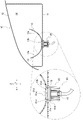
- the vehicle lamp 10 of the first embodiment is used as a lighting tool for a vehicle such as an automobile, and is used, for example, for a head lamp, a fog lamp, a daytime running lamp, a clearance lamp, or the like.
- the traveling direction of the vehicle when traveling straight and the direction of irradiating light is the optical axis direction (Z in the drawing, and the irradiating side is the front side), and the light is mounted on the vehicle.
- the vertical direction is the vertical direction (referred to as Y in the drawing)
- the direction orthogonal to the optical axis direction and the vertical direction is defined as the width direction (referred to as X in the drawing).
- the vehicle lamp 10 includes a lamp housing 11, a lamp lens 12, a reflector 13, and a light source unit 20.
- the lamp housing 11 is formed of a light-impermeable member such as a colored or painted resin material, and has a hollow shape with an opening at the front and a closure at the rear.
- the lamp housing 11 is provided with a mounting hole 11a that penetrates the closed rear end. A plurality of notches and stoppers are provided at substantially equal intervals on the edge of the mounting hole 11a.
- the lamp lens 12 is made of a light-transmitting member such as a transparent resin portion material or a glass member, and has a shape capable of covering the open front end of the lamp housing 11.
- the lamp lens 12 is fixed in a sealed state in the opening of the lamp housing 11 to ensure watertightness.
- the lamp housing 11 and the lamp lens 12 are partitioned to form a lamp chamber 14.
- the reflector 13 is a light distribution control unit that controls the light distribution of the light emitted from the light source unit 20, and is fixed to the lamp housing 11 or the like and arranged in the light chamber 14.
- the reflector 13 has a curved shape having a focal point in the vicinity of the light source 21 (see FIG. 2 and the like) of the light source unit 20, the inner surface is a reflecting surface 13a that reflects light, and a mounting hole 13b is provided at the bottom. There is.
- the mounting holes 13b have a positional relationship of communicating with the mounting holes 11a of the lamp housing 11 in a state where the reflector 13 is arranged in the lamp chamber 14.
- the reflector 13 is formed as a member different from the lamp housing 11, but an integrated configuration, that is, the inner surface of the lamp housing 11 may be used as a reflecting surface, or another configuration may be used. It is not limited to the configuration of Example 1. Further, instead of the reflector (reflecting surface), a light guide member may be provided on the front side of the light source unit 20 in the optical axis direction to emit light at a position different from that of the light source 21 or in a region having a different size. The configuration is not limited to the first embodiment. Even when the light guide member is provided in this way, the vehicle lamp 10 can be used as, for example, a headlamp, a fog lamp, a daytime running lamp, a clearance lamp, or the like.
- a light source unit 20 is arranged in the lamp chamber 14 through a mounting hole 11a of the lamp housing 11 and a mounting hole 13b of the reflector 13.
- the light source unit 20 is detachably attached to the mounting hole 11a with a sealing member (O-ring) 15 interposed between the light source unit 20 and the lamp housing 11.
- the light source unit 20 may be provided in the light chamber 14 via a vertical optical axis adjusting mechanism or a horizontal optical axis adjusting mechanism.
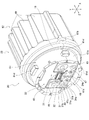
- the light source unit 20 includes a light source 21, a heat radiating member 22, a socket 23, and a feeding member 24.
- the light source 21 is formed as a submount type light emitting element in which a light emitting chip 32 is provided on a submount substrate 31.
- the mounting surface 31a of the submount board 31 has a substantially rectangular shape when viewed from the front side in the optical axis direction, and the light emitting chip 32 is mounted on the upper half when the front view of FIG. 2 is viewed.
- the connection terminals 31b are provided in pairs with each other. In the light source 21, the light emitting chip 32 and both connection terminals 31b are electrically connected via a submount substrate 31 (its electric circuit), and when power is supplied between both connection terminals 31b, the light emitting chip 32 is turned on. Let me.
- the light emitting chip 32 is a self-luminous semiconductor type light source such as an LED (Light Emitting Diode), an EL (organic EL) LD chip (laser diode chip), and is referred to as an LED chip in the first embodiment.
- the light emitting chip 32 is located near the focal point of the reflector 13 with the light source unit 20 assembled.
- the heat radiating member 22 is a heat sink member that transfers (escapes) the heat generated by the light source 21 to the socket 23, and is made of a metal material or a resin material having high thermal conductivity. It is formed by die casting. As shown in FIGS. 3 and 4, the heat radiating member 22 has a base portion 41 and a radiating fin portion 42.
- the base portion 41 has a plate shape orthogonal to the optical axis direction, the front side in the optical axis direction is the installation surface 43, and the opposite side (rear side in the optical axis direction) is continuous with the heat radiation fin portion 42. It is said to be the surface 44.
- the installation surface 43 is provided with a convex surface portion 43a that protrudes relatively to the front side in the optical axis direction and a concave surface portion 43b that is relatively recessed to the rear side in the optical axis direction.
- the convex surface portion 43a has a T-shape including the central region of the installation surface 43, and the light source 21 is installed in the central region thereof.
- the light source 21 is attached to the convex surface portion 43a (the central region thereof) via the adhesive layer 33 having thermal conductivity.
- the adhesive layer 33 attaches the light source 21 (its submount substrate 31) to the convex surface portion 43a, and is made of a material such as an epoxy resin adhesive, a silicon resin adhesive, or an acrylic resin adhesive, and is in a liquid form and flows. It is in the form of a shape, a tape, or the like.
- the concave surface portion 43b has a U-shape surrounding the portion of the convex surface portion 43a to which the light source 21 is attached, and is provided with a pair of caulking protrusions 45 and a pair of terminal holes 46.
- the protrusions 45 for both caulking are formed in a columnar shape protruding from the concave surface portion 43b in the optical axis direction, and are provided in pairs so as to sandwich the light source 21 in the width direction.
- Each of the caulking protrusions 45 is provided on the same straight line as the connecting fin 52 described later in the optical axis direction (see FIG. 6).
- the holes 46 for both terminals are through holes that penetrate the base portion 41, and are capable of passing the pin terminals 24a of the power feeding member 24.
- a circuit board 47 is provided on the concave surface portion 43b.
- the circuit board 47 transmits a control signal from a control circuit mounted on the vehicle to the light source 21, and is appropriately provided with a plurality of elements such as a capacitor.
- the circuit board 47 has a shape that fits into the concave surface portion 43b, that is, a U-shaped plate member that surrounds a portion of the convex surface portion 43a to which the light source 21 is attached, and is provided on the concave surface portion 43b in the optical axis direction. The height position is almost equal to 43a.
- the circuit board 47 is provided with a pair of caulking holes 47a, a pair of terminal connection holes 47b, and a pair of connection terminals 47c.
- the caulking holes 47a are through holes that penetrate the circuit board 47 in the optical axis direction, and are paired so as to sandwich the light source 21 in the width direction.
- Each caulking hole 47a is provided at a position corresponding to a pair of caulking projections 45 provided on the concave surface portion 43b of the heat radiating member 22, and the corresponding caulking projections 45 can be passed therethrough. ..
- Each terminal connection hole 47b is a through hole that penetrates the circuit board 47 in the optical axis direction, and is provided at a position corresponding to a pair of terminal holes 46 provided in the concave surface portion 43b of the heat dissipation member 22 to supply power. It is possible to pass the pin terminal 24a of the member 24.
- Each terminal connection hole 47b is electrically connected to the control circuit in the circuit board 47, and is electrically connected to the power feeding member 24 by fixing the corresponding pin terminal 24a with solder or the like.
- Both connection terminals 47c are provided at positions corresponding to the connection terminals 31b on the mounting surface 31a of the submount board 31, and are electrically connected to the control circuit formed on the circuit board 47.
- This circuit board 47 is attached to the concave surface portion 43b via the adhesive sheet 48.
- the adhesive sheet 48 is provided with a pair of caulking notches 48a and a pair of terminal connection notches 48b.
- the notch 48a for both caulking is provided corresponding to the hole 47a for both caulking, that is, the projection 45 for both caulking, and the corresponding projection 45 for caulking can be passed through.
- Both terminal connection notches 48b are provided corresponding to both terminal connection holes 47b, that is, both pin terminals 24a, and are capable of passing the corresponding pin terminals 24a.
- the circuit board 47 is electrically connected to the light source 21 by a pair of bonding wires 49 provided by wire bonding.
- the bonding wire 49 is paired so as to bridge the connection terminals 31b of the submount board 31 of the light source 21 attached to the convex surface portion 43a and the connection terminals 47c of the circuit board 47 attached to the concave surface portion 43b. It is provided for the purpose of.
- each bonding wire 49 is electrically connected to the connection terminal 31b at one end and to the connection terminal 47c at the other end by wire bonding using ultrasonic waves.
- the light source 21 (the submount substrate 31 thereof) and the circuit board 47 may be electrically connected, and are not limited to the configuration of the first embodiment.
- the heat radiation fin portion 42 has a plurality of parallel fins 51 projecting rearward in the optical axis direction from the heat radiation surface 44 of the base portion 41.
- Each parallel fin 51 has a flat plate shape orthogonal to the vertical direction on the heat radiation surface 44 of the base portion 41, and is provided side by side (in parallel) at a predetermined interval in the vertical direction. That is, each of the parallel fins 51 has a flat outer surface on each of the upper and lower surfaces due to the flat plate shape, and the outer surfaces of the parallel fins 51 are arranged in parallel with each other facing each other.
- the thickness of the number of parallel fins 51 may be appropriately set, and is set to 4 in the first embodiment, and is in the shape of a thick plate (up and down with respect to the size on a plane orthogonal to the parallel fins 51A in the second embodiment in the vertical direction). The ratio of dimensions in the direction is large).
- the heat radiation fin portion 42 of the first embodiment is provided with a connecting fin 52.
- the connecting fins 52 bridge each parallel fin 51 in the parallel direction thereof, and two connecting fins 52 are provided in the first embodiment.
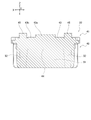
- the two connecting fins 52 are located on the same straight line as the caulking protrusion 45 provided on the concave portion 43b of the installation surface 43 in the optical axis direction (see FIG. 6).
- the two connecting fins 52 span the vicinity of the widthwise end of each parallel fin 51 up and down, that is, the parallel fin 51 on the lowermost side is passed through the two parallel fins 51 in the middle from the parallel fin 51 on the uppermost side. It is supposed to lead to.
- the double caulking protrusion 45 of the first embodiment has a position where the parallel fin 51 overlaps with the parallel fin 51, that is, a position where the parallel fin 51 and the connecting fin 52 intersect and a position on the same straight line in the optical axis direction. (See FIG. 6).
- a pair of terminal holes 46 penetrate the base portion 41, so that the holes 46 for both terminals are positioned below the bottom parallel fin 51 on the heat radiating surface 44.
- the heat radiating member 22 is provided with a pair of positioning protrusions 53 on the heat radiating surface 44 of the base portion 41.
- Each positioning protrusion 53 is located on the heat radiating surface 44 outside the pair of terminal holes 46 in the width direction, and has a columnar shape protruding rearward in the optical axis direction from the heat radiating surface 44.
- the socket 23 is made of a material having thermal conductivity, and in Example 1, it is made of a resin member.
- the socket 23 has a socket main body portion 61 and a socket heat radiating portion 62, and has a function of releasing heat transmitted from the heat radiating member 22 to the outside (mainly the socket heat radiating portion 62).
- the front side of the socket main body 61 in the optical axis direction is a mounting surface 63, and the opposite side (rear side in the optical axis direction) is a heat dissipation surface 64 continuous with the socket heat dissipation portion 62.
- the mounting surface 63 has a cylindrical peripheral wall 61a whose outer diameter is slightly smaller than the inner diameter of the mounting hole 11a of the lamp housing 11, and a flange wall 61b protruding outward along a surface orthogonal to the optical axis direction from the peripheral wall 61a.
- a bottom wall 61c that closes the rear side of the 61a in the optical axis direction is provided.
- the socket main body 61 is divided into a mounting surface 63 side and a heat radiating surface 64 side by a bottom wall 61c.
- the socket main body 61 is provided with four mounting projections 61d that project outward from the peripheral wall 61a in a direction orthogonal to the optical axis direction.
- the four mounting protrusions 61d are provided at substantially equal intervals in the circumferential direction of the peripheral wall 61a, and can pass through a notch provided at the edge of the mounting hole 11a of the lamp housing 11. After passing through the above-mentioned notch, each mounting projection 61d is addressed to the stopper portion by changing the rotational posture of the socket main body portion 61 with respect to the lamp housing 11, so that the peripheral edge of the mounting hole 11a is formed between the mounting projection 61d and the flange wall 61b.
- the portion and the sealing member 15 can be sandwiched (see FIG. 1). Thereby, each mounting projection 61d can detachably mount the socket 23, that is, the light source unit 20 to the lamp housing 11 via the sealing member 15 in cooperation with the flange wall 61b.
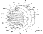
- a fin groove 66 In the socket main body 61, a fin groove 66, an installation hole 67, and a positioning hole 68 are provided inside the peripheral wall 61a on the mounting surface 63.
- the fin groove portion 66 can be fitted with the heat radiation fin portion 42, and has a shape in which the heat radiation fin portion 42 is inverted. That is, in the fin groove portion 66, the parallel groove 66a that fits the four parallel fins 51 and the connecting groove 66b that fits the two connecting fins 52 are combined in a grid pattern. Therefore, the fin groove portion 66 can receive the heat radiation fin portion 42 so as to appropriately mesh with the heat radiation fin portion 42.
- the installation hole 67 is a place where the power feeding member 24 (see FIG. 3) is installed, and penetrates the bottom wall 61c in the optical axis direction.
- the power feeding member 24 has a connector 16 on the power supply side (see FIG. 1) connected mechanically and detachably and electrically intermittently, and supplies power from the connector 16 to the light source unit 20. do.
- the power feeding member 24 has a pair of pin terminals 24a, and the pin terminals 24a are electrically connected to the terminal connection holes 47b so that electric power can be supplied to the circuit board 47.
- the installation hole 67 has a shape that imitates the outer shape of the feeding member 24, and the insulating property of the feeding member 24 is ensured by fitting the feeding member 24 through an insulating material.
- the installation hole 67 communicates with a mounting location (inside thereof) provided on the heat radiating surface 64.
- a mounting location inside thereof
- the connecting terminal on the rear side in the optical axis direction is exposed in the mounting location, and the connector 16 on the power supply side (see FIG. 1) is mounted at the mounting location.
- the connecting terminal is electrically connected to the connecting terminal of the connector 16.
- the positioning holes 68 are paired corresponding to the pair of positioning protrusions 53 of the heat radiating member 22, and are holes into which the respective positioning protrusions 53 can be inserted.
- Each positioning hole 68 is located outside the installation hole 67 in the width direction on the mounting surface 63, and is a hole extending to the rear side in the optical axis direction.
- Each positioning hole 68 is inserted with a corresponding positioning protrusion 53 to determine a relative position between the heat radiating member 22 and the socket 23. Therefore, in the first embodiment, the pair of positioning protrusions 53 of the heat radiating member 22 serve as the heat radiating side positioning portion, and the pair of positioning holes 68 of the socket 23 serve as the socket side positioning portion.
- the heat dissipation side positioning portion and the socket side positioning portion determine the relative positions of the heat dissipation member 22 and the socket 23, the positions and numbers may be appropriately set, and the protrusions and holes may be exchanged.
- the configuration may be other than that of the first embodiment.
- the socket heat radiating unit 62 releases (radiates) the heat transmitted from the heat radiating member 22 to the outside, and has a plurality of fins 69.
- Each fin 69 has a plate shape along a plane orthogonal to the width direction, and is arranged in parallel in the width direction while projecting to the rear side in the optical axis direction from the heat radiation surface 64.
- On the heat radiating surface 64 as shown in FIG. 1, a mounting portion into which the connector 16 on the power supply side is inserted is provided at a location where each fin 69 is not provided.
- the connector 16 is mechanically detachably attached, and when the connector 16 is attached, the connection terminal is attached to the connection terminal of the power feeding member 24 (see FIG. 3 and the like) provided in the installation hole 67. Connect electrically.
- This light source unit 20 is assembled as follows. First, as shown in FIG. 3, the power feeding member 24 is fitted into the installation hole 67 of the mounting surface 63 of the socket 23 via the insulating material. Further, on the installation surface 43 of the base portion 41 of the heat radiation member 22, the light source 21 is attached to the central region of the convex surface portion 43a via the adhesive layer 33, and the circuit board 47 is attached to the concave surface portion 43b via the adhesive sheet 48. Be done. At this time, in the adhesive sheet 48 and the circuit board 47, the pair of caulking protrusions 45 of the concave surface portion 43b are passed through the corresponding caulking notch 48a and the caulking hole 47a, and the pair of terminal holes 46 of the concave surface portion 43b.
- the terminal connection hole 47b and the terminal connection notch 48b corresponding to the above are overlapped with each other. After that, the tips of both caulking protrusions 45 are crushed and plastically deformed, that is, caulked, so that the circuit board 47 is firmly fixed by the concave surface portion 43b.
- the pair of bonding wires 49 are arranged so as to bridge the connection terminals 31b of the submount board 31 of the light source 21 and the connection terminals 47c of the circuit board 47. Then, both ends of each bonding wire 49 addressed to each connection terminal 31b and each connection terminal 47c are electrically connected by wire bonding using ultrasonic waves.
- the heat conductor 71 is provided in the fin groove portion 66 of the mounting surface 63 of the socket body portion 61 of the socket 23. The heat conductor 71 is provided to enhance heat transfer between the heat dissipation fin portion 42 of the heat dissipation member 22 and the fin groove portion 66 of the socket 23, and in the first embodiment, heat conduction grease is used.
- each positioning protrusion 53 is inserted into the corresponding positioning hole 68, the heat radiating surface 64 is addressed to the mounting surface 63, and the heat radiating member 22 is press-fitted into the socket 23.
- ultrasonic waves can be appropriately used, that is, ultrasonic waves may or may not be used.
- the heat radiation fin portion 42 of the heat radiation surface 64 is fitted into the fin groove portion 66 of the mounting surface 63, and is provided in the installation hole 67 of the socket 23.
- Each pin terminal 24a of the power feeding member 24 is passed through the corresponding terminal connection hole 47b of the circuit board 47 through the corresponding terminal hole 46 of the socket main body 61.
- the light source unit 20 can be assembled by electrically connecting each pin terminal 24a to the terminal connection hole 47b using solder or the like.
- the light source unit 20 is inserted into the mounting hole 11a of the lamp housing 11 from the light source 21 side in a state where the sealing member 15 is provided toward the flange wall 61b while surrounding the peripheral wall 61a, and each of the sockets 23 thereof.
- the mounting projection 61d is passed through a notch provided at the edge of the mounting hole 11a.
- the light source unit 20 changes the rotational posture of the socket main body 61 with respect to the lamp housing 11 so that the mounting projections 61d are addressed to the corresponding stoppers, so that the flange wall 61b and the peripheral edge of the mounting hole 11a are brought into contact with each other. It is attached to the lamp housing 11 with the sealing member 15 sandwiched between them.
- the lamp fixture 10 for a vehicle By attaching the reflector 13 and the lamp lens 12 to the lamp housing 11, the lamp fixture 10 for a vehicle is assembled.
- the light source 21 and the circuit board 47 in the light source unit 20 are inside the lighting chamber 14 through the mounting holes 11a of the lamp housing 11 and the mounting holes 13b of the reflector 13, and are on the reflecting surface 13a side of the reflector 13. Is located in.
- the vehicle lamp 10 has a connector 16 on the power supply side (see FIG. 1) attached to a socket 23 of the light source unit 20 attached to the lamp housing 11 to supply electric power to the circuit board 47 via the power feeding member 24.
- the light source 21 can be turned on and off as appropriate.
- the heat dissipation fin portion 42 of the heat dissipation member 22 is fitted into the fin groove portion 66 of the socket 23, the heat generated by the light source 21 can be efficiently transferred from the heat dissipation member 22 to the socket 23. , The heat can be released from the socket 23 to the outside. Therefore, the vehicle lamp 10 can appropriately cool the light source 21 and can appropriately turn on the light source 21.
- the vehicle lamp 10 is also provided with the socket heat radiating portion 62 (each fin 69) in the socket 23, the heat transferred from the heat radiating member 22 to the socket 23 can be efficiently radiated, and the heat radiating member can be radiated. The heat dissipation of 22 can be promoted.
- a plurality of fins are provided in the heat radiating member, and a connector portion (corresponding to the socket 23 of the present disclosure) is combined with the heat radiating member by insert molding so as to fill the space between the fins.
- a heat dissipation member provided with a plurality of fins is appropriate in the mold. Need to keep in position.
- the vehicle lamp 10 is provided with a fin groove 66 for fitting the heat radiation fin portion 42 of the heat radiation member 22 and a pair of positioning holes 68 on the mounting surface 63 of the socket 23, and the heat radiation member.
- a pair of positioning protrusions 53 are provided on the heat radiating surface 44 of the 22. Therefore, the vehicle lamp 10 is positioned by the positioning holes 68 and the positioning protrusions 53, and the heat radiating member 22 and the socket 23 are attached so that the heat radiating fin portion 42 is fitted into the fin groove portion 66. be able to.
- the vehicle lamp 10 since the vehicle lamp 10 is not insert-molded, it is possible to prevent a through hole from being formed in the socket 23, and the fin groove portion 66 and the heat radiation fin portion 42 are engaged with each other to engage the heat radiation member 22 and the socket 23. Can be assembled with. Therefore, the vehicle lamp 10 can prevent moisture from entering the periphery of the light source 21 and the circuit board 47, and can efficiently release the heat generated by the light source 21 from the heat radiating member 22.
- the vehicle lamp 10 is provided with a plurality of parallel fins 51 and a plurality of connecting fins 52 in the heat radiation fin portion 42. Therefore, the vehicle lamp 10 can suppress the deformation of the heat radiating fin portion 42 when the tip of both caulking protrusions 45 is caulked to fix the circuit board 47 to the concave surface portion 43b in the heat radiating member 22. This is due to the following.
- the heat radiating member 22 when crimping the tip of the caulking protrusion 45, pressure is applied between the heat radiating fin portion 42 on the opposite side of the tip, so that the radiating fin portion 42 has only a plurality of parallel fins 51. If the above, each parallel fin 51 may be deformed so as to fall or bend.
- each parallel fin 51 is bridged in the parallel direction of each parallel fin 51 to provide a plurality of connecting fins 52.
- the connecting fins 52 prevent the spacing of the parallel fins 51 from changing. Therefore, in the vehicle lamp 10, even if the tips of both caulking protrusions 45 are caulked, the heat radiation fin portion 42 can be prevented from being deformed.
- the vehicle lamp 10 is provided with two connecting fins 52 on the same straight line as the caulking protrusion 45 in the optical axis direction.
- both the caulking protrusions 45 project in the optical axis direction
- the pressure applied between the heat radiating fin portion 42 when the tip is crimped also follows the optical axis direction. Therefore, the vehicle lamp 10 can receive the pressure applied when crimping the tip of each caulking protrusion 45 by each connecting fin 52 on the same straight line as each caulking protrusion 45, and each connecting fin thereof. It is possible to effectively suppress the deformation of the heat radiation fin portion 42 including the 52.
- both caulking protrusions 45 of the first embodiment are located on the same straight line in the optical axis direction as the positions where the parallel fins 51 and the connecting fins 52 intersect, the tips of the caulking protrusions 45 are crimped. It is possible to more effectively suppress the deformation of the heat radiating fin portion 42 due to the pressure applied during the operation.
- the circuit board 47 is firmly fixed by the concave surface portion 43b by caulking the two caulking protrusions 45. Therefore, in the vehicle lamp 10, both ends of the pair of bonding wires 49 are electrically connected to each connection terminal 31b of the light source 21 and each connection terminal 47c of the circuit board 47 by wire bonding using ultrasonic waves. be able to. This is because if the circuit board 47 is attached to the concave portion 43b only by the adhesive sheet 48, there is a possibility that the circuit board 47 may fall off from the concave portion 43b or be displaced during wire bonding using ultrasonic waves. Due to something.
- the vehicle lamp 10 can electrically connect the light source 21 and the circuit board 47 at an appropriate position, and can irradiate desired light.
- the vehicle lamp 10 has each parallel fin 51 in the shape of a thick plate. Therefore, as compared with the case where the vehicle lamp 10 has a thin plate shape (parallel fins 51A of the second embodiment), the strength of the heat radiation fin portion 42 can be increased and the heat capacity can be secured. Moreover, the vehicle lamp 10 is provided with the connecting fins 52 by straddling the plate-shaped parallel fins 51. Therefore, the vehicle lamp 10 can increase the surface area of the heat radiating fin portion 42 as compared with the case where only the parallel fins 51 are provided, and the heat generated by the light source 21 is released more efficiently from the heat radiating member 22. be able to.
- the vehicle lamp 10 of the first embodiment can obtain each of the following effects.
- the heat dissipation member 22 has a heat dissipation fin portion 42 and a heat dissipation side positioning portion (positioning protrusion 53), and the socket 23 has a fin groove portion 66 and a socket side positioning portion (positioning hole 68). Therefore, the vehicle lamp 10 is positioned by the heat radiating side positioning portion and the socket side positioning portion, and the heat radiating member 22 and the socket 23 are attached so that the heat radiating fin portion 42 is fitted into the fin groove portion 66. be able to. As a result, since the vehicle lamp 10 is not insert-molded, it is possible to prevent the socket 23 from forming a through hole, and it is possible to prevent moisture from entering the periphery of the light source 21 and the circuit board 47. The heat generated by the light source 21 can be efficiently dissipated from the heat radiating member 22.
- the vehicle lamp 10 is provided with a heat conductor 71 between the heat radiation fin portion 42 and the fin groove portion 66. Therefore, the vehicle lamp 10 can suppress the formation of a gap between the fitted fin groove portion 66 and the heat radiation fin portion 42, and can more efficiently release the heat generated by the light source 21 from the heat radiation member 22. ..
- the vehicle lamp 10 has a plurality of parallel fins 51 in which the heat radiating fin portion 42 is formed into a flat plate shape and the flat outer surfaces thereof are opposed to each other and arranged in parallel. Therefore, the vehicle lamp 10 can secure a surface area in the heat radiating fin portion 42 while having a simple shape, and heat generated by the light source 21 can be easily fitted into the fin groove portion 66 from the heat radiating member 22. It can be escaped more efficiently.
- the vehicle lamp 10 has a connecting fin 52 in which the heat radiating fin portion 42 projects from the heat radiating surface 44 while being bridged in the parallel direction of the plurality of parallel fins 51. Therefore, the vehicle lamp 10 can increase the surface area of the heat radiating fin portion 42 as compared with the case where only the parallel fins 51 are provided while ensuring the strength of the heat radiating fin portion 42.
- the vehicle lamp 10 is provided with a caulking hole 47a in the substrate (circuit board 47) and a caulking protrusion 45 protruding from the installation surface 43 in the heat radiating member 22. Therefore, in the vehicle lighting fixture 10, the substrate is firmly fixed to the installation surface 43 of the heat dissipation member 22 by caulking the tip of the caulking projection 45 in a state where the caulking projection 45 is passed through the caulking hole 47a. can.
- the vehicle lamp 10 is provided with the caulking protrusion 45 on the same straight line as the connecting fin 52 in the direction orthogonal to the substrate (circuit board 47). Therefore, the vehicle lamp 10 can prevent the heat radiation fin portion 42 from being deformed when the tip of the caulking protrusion 45 is crimped.
- the vehicle lamp 10 of the first embodiment as the vehicle lamp according to the present disclosure can efficiently release the heat from the light source 21 while suppressing the entry of moisture into the light source 21 side.
- the vehicle lamp 10A of the second embodiment which is an embodiment of the present disclosure, will be described with reference to FIGS. 7 to 10.
- the vehicle lamp 10A is a modification of the configuration of the light source unit 20 in the vehicle lamp 10 of the first embodiment. Since the vehicle lighting fixture 10A has the same basic concept and configuration as the vehicle lighting fixture 10 of the first embodiment, the same reference numerals are given to the parts having the same configuration, and detailed description thereof will be omitted.
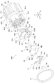
- the vehicle lamp 10A of the second embodiment has the light source unit 20A shown in FIGS. 7 and 8.
- the light source unit 20A is different from the light source unit 20 in the configuration of the heat radiating member 22A and the socket 23A.
- the convex surface portion 43aA on the installation surface 43A of the base portion 41A has an area substantially equal to that of the light source 21 when viewed from the front side in the optical axis direction. That is, unlike the convex surface portion 43a of the first embodiment, the convex surface portion 43aA is not intended to extend above the portion where the light source 21 is installed. Therefore, the concave surface portion 43bA has a shape that surrounds the convex surface portion 43aA.
- the installation surface 43A of the heat dissipation member 22A has the same configuration as the installation surface 43 of the heat dissipation member 22 of the first embodiment, and the light source 21, the circuit board 47, and both bonding wires 49 are included in the first embodiment. It can be installed in the same way as.
- the configuration of the heat radiating fin portion 42A on the radiating surface 44A is different from that of the radiating fin portion 42 of the first embodiment.
- the heat radiating fin portion 42A has a plurality of parallel fins 51A protruding rearward in the optical axis direction from the heat radiating surface 44A, but the heat radiating fin portion 42A is not provided with the one corresponding to the connecting fin 52 of the first embodiment.
- the parallel fins 51A have a flat plate shape orthogonal to the vertical direction on the heat radiating surface 44A, and are provided side by side (in parallel) at predetermined intervals in the vertical direction.
- each of the parallel fins 51A has a flat outer surface on each of the upper and lower surfaces due to the flat plate shape, and the outer surfaces of the parallel fins 51A are arranged in parallel with each other facing each other.
- the number of parallel fins 51A is 6 in Example 1, which is thinner (thin plate shape) than the connecting fins 52 in Example 1.
- the fin groove portion 66A on the mounting surface 63A of the socket main body portion 61A has a shape in which the heat radiation fin portion 42A is inverted. That is, in the fin groove portion 66A, parallel grooves 66aA compatible with the six parallel fins 51 are arranged in parallel in the vertical direction. Therefore, the fin groove portion 66A can receive the heat radiation fin portion 42A so that the heat radiation fin portion 42A properly meshes with the heat radiation fin portion 42A.
- the vehicle lamp 10A can be assembled in the same manner as the vehicle lamp 10 of the first embodiment. Similar to the vehicle lamp 10 of the first embodiment, the vehicle lamp 10A has the heat radiation fin portion 42A of the heat radiation member 22A fitted into the fin groove portion 66A of the socket 23A without performing insert molding. Therefore, the vehicle lamp 10A can prevent moisture from entering the periphery of the light source 21 and the circuit board 47, and efficiently release the heat generated by the light source 21 from the heat radiating member 22A to the external socket 23A. Can be done.
- the vehicle lamp 10A of the second embodiment can obtain the following effects. Since the vehicle lamp 10A basically has the same configuration as the vehicle lamp 10 of the first embodiment, the same effect as that of the first embodiment can be obtained.
- the vehicle lamp 10A has, in the light source unit 20A, a plurality of parallel fins 51A in which the heat radiation fin portion 42A projects rearward in the optical axis direction from the heat radiation surface 44A. Therefore, in the vehicle lighting tool 10A, the shapes of the heat radiating fin portion 42A and the fin groove portion 66A can be simplified as compared with the vehicle lighting tool 10 of the first embodiment, the manufacturing cost can be suppressed, and the heat radiating fin portion 42A can be reduced. The fitting into the fin groove portion 66A can be made more reliable. Further, in the vehicle lamp 10A, in the light source unit 20A, each parallel fin 51A has a thin plate shape, so that the surface area can be increased as compared with each of the thick plate-shaped parallel fins 51 as in the first embodiment. ..
- the vehicle lamp 10A of the second embodiment as the vehicle lamp according to the present disclosure can efficiently release the heat from the light source 21 while suppressing the entry of moisture into the light source 21 side.
- vehicle lamps of the present disclosure have been described based on each embodiment, the specific configuration is not limited to each embodiment and does not deviate from the gist of the invention according to each claim. As long as the design is changed or added, it is permissible.
- the heat conductor 71 is provided between the heat radiation fin portions 42, 42A and the fin groove portions 66, 66A.
- the thermal conductor 71 may not be provided and is not limited to the configuration of each embodiment.
- the submount type light source 21 is used and is electrically connected to the circuit board 47 by a pair of bonding wires 49 provided by wire bonding.
- the light source may be any as long as it is attached to the heat radiating members 22 and 22A and is appropriately turned on and off by supplying electric power from the connector 16 on the power supply side attached to the sockets 23 and 23A. Not limited.
- the heat radiation fin portions 42 and 42A have the above configuration.
- the heat radiating fin portion may have a so-called fin shape that expands the surface area in order to enhance the heat radiating property of the heat radiating members 22 and 22A, and is not limited to the configuration of each embodiment.
- the fin groove portions 66 and 66A have the above configuration.
- the fin groove portion may be of a shape that allows the heat radiation fin portion to be fitted, that is, has a shape in which the heat radiation fin portion is inverted, and is not limited to the configuration of each embodiment.
Landscapes
- Engineering & Computer Science (AREA)
- General Engineering & Computer Science (AREA)
- Physics & Mathematics (AREA)
- Microelectronics & Electronic Packaging (AREA)
- Optics & Photonics (AREA)
- Non-Portable Lighting Devices Or Systems Thereof (AREA)
- Arrangement Of Elements, Cooling, Sealing, Or The Like Of Lighting Devices (AREA)
Abstract
Priority Applications (3)
| Application Number | Priority Date | Filing Date | Title |
|---|---|---|---|
| US18/247,202 US12492799B2 (en) | 2020-09-30 | 2021-09-29 | Lighting fixture for vehicle |
| CN202180067109.5A CN116235003A (zh) | 2020-09-30 | 2021-09-29 | 车辆用灯具 |
| EP21875729.2A EP4224059B1 (fr) | 2020-09-30 | 2021-09-29 | Appareil d'éclairage pour véhicule |
Applications Claiming Priority (2)
| Application Number | Priority Date | Filing Date | Title |
|---|---|---|---|
| JP2020-165627 | 2020-09-30 | ||
| JP2020165627A JP7608766B2 (ja) | 2020-09-30 | 2020-09-30 | 車両用灯具 |
Publications (1)
| Publication Number | Publication Date |
|---|---|
| WO2022071432A1 true WO2022071432A1 (fr) | 2022-04-07 |
Family
ID=80950650
Family Applications (1)
| Application Number | Title | Priority Date | Filing Date |
|---|---|---|---|
| PCT/JP2021/035962 Ceased WO2022071432A1 (fr) | 2020-09-30 | 2021-09-29 | Appareil d'éclairage pour véhicule |
Country Status (5)
| Country | Link |
|---|---|
| US (1) | US12492799B2 (fr) |
| EP (1) | EP4224059B1 (fr) |
| JP (1) | JP7608766B2 (fr) |
| CN (1) | CN116235003A (fr) |
| WO (1) | WO2022071432A1 (fr) |
Cited By (1)
| Publication number | Priority date | Publication date | Assignee | Title |
|---|---|---|---|---|
| EP4425044A4 (fr) * | 2021-10-29 | 2025-10-01 | Ichikoh Industries Ltd | Lampe de véhicule |
Families Citing this family (1)
| Publication number | Priority date | Publication date | Assignee | Title |
|---|---|---|---|---|
| JP7673418B2 (ja) | 2021-02-08 | 2025-05-09 | 市光工業株式会社 | 車両用灯具 |
Citations (7)
| Publication number | Priority date | Publication date | Assignee | Title |
|---|---|---|---|---|
| JP2009146706A (ja) * | 2007-12-13 | 2009-07-02 | Harison Toshiba Lighting Corp | 車両用灯具 |
| JP2011171277A (ja) * | 2010-01-19 | 2011-09-01 | Ichikoh Ind Ltd | 車両用灯具の半導体型光源の光源ユニット、車両用灯具 |
| JP2011253774A (ja) | 2010-06-03 | 2011-12-15 | Ichikoh Ind Ltd | 車両用灯具の半導体型光源の光源ユニット、車両用灯具 |
| JP2013219289A (ja) * | 2012-04-11 | 2013-10-24 | Harison Toshiba Lighting Corp | 光半導体光源及び車両用照明装置 |
| JP2016048607A (ja) * | 2014-08-27 | 2016-04-07 | 東芝ライテック株式会社 | ソケットおよび照明装置 |
| JP2017152285A (ja) * | 2016-02-26 | 2017-08-31 | 株式会社小糸製作所 | 車両用灯具 |
| JP2018067451A (ja) * | 2016-10-19 | 2018-04-26 | スタンレー電気株式会社 | 車両用灯具用光源モジュール及び車両用灯具 |
Family Cites Families (6)
| Publication number | Priority date | Publication date | Assignee | Title |
|---|---|---|---|---|
| CN101646898B (zh) * | 2007-04-03 | 2013-07-17 | 奥斯兰姆有限公司 | 半导体灯模块 |
| US7922364B2 (en) | 2009-03-10 | 2011-04-12 | Osram Sylvania, Inc. | LED lamp assembly |
| JP2012084280A (ja) * | 2010-10-07 | 2012-04-26 | Ichikoh Ind Ltd | 車両用灯具の半導体型光源の光源ユニット、車両用灯具 |
| AT510454B1 (de) | 2010-10-14 | 2013-04-15 | Zizala Lichtsysteme Gmbh | Led-fahrzeugscheinwerfer |
| CN105042468B (zh) * | 2011-06-13 | 2018-10-12 | 株式会社小糸制作所 | 车辆用前照灯、散热机构、发光装置及光源固定部件 |
| WO2013153938A1 (fr) | 2012-04-11 | 2013-10-17 | 東芝ライテック株式会社 | Source lumineuse à semi-conducteurs optiques, et appareil d'éclairage pour véhicule |
-
2020
- 2020-09-30 JP JP2020165627A patent/JP7608766B2/ja active Active
-
2021
- 2021-09-29 US US18/247,202 patent/US12492799B2/en active Active
- 2021-09-29 WO PCT/JP2021/035962 patent/WO2022071432A1/fr not_active Ceased
- 2021-09-29 CN CN202180067109.5A patent/CN116235003A/zh active Pending
- 2021-09-29 EP EP21875729.2A patent/EP4224059B1/fr active Active
Patent Citations (7)
| Publication number | Priority date | Publication date | Assignee | Title |
|---|---|---|---|---|
| JP2009146706A (ja) * | 2007-12-13 | 2009-07-02 | Harison Toshiba Lighting Corp | 車両用灯具 |
| JP2011171277A (ja) * | 2010-01-19 | 2011-09-01 | Ichikoh Ind Ltd | 車両用灯具の半導体型光源の光源ユニット、車両用灯具 |
| JP2011253774A (ja) | 2010-06-03 | 2011-12-15 | Ichikoh Ind Ltd | 車両用灯具の半導体型光源の光源ユニット、車両用灯具 |
| JP2013219289A (ja) * | 2012-04-11 | 2013-10-24 | Harison Toshiba Lighting Corp | 光半導体光源及び車両用照明装置 |
| JP2016048607A (ja) * | 2014-08-27 | 2016-04-07 | 東芝ライテック株式会社 | ソケットおよび照明装置 |
| JP2017152285A (ja) * | 2016-02-26 | 2017-08-31 | 株式会社小糸製作所 | 車両用灯具 |
| JP2018067451A (ja) * | 2016-10-19 | 2018-04-26 | スタンレー電気株式会社 | 車両用灯具用光源モジュール及び車両用灯具 |
Non-Patent Citations (1)
| Title |
|---|
| See also references of EP4224059A4 |
Cited By (1)
| Publication number | Priority date | Publication date | Assignee | Title |
|---|---|---|---|---|
| EP4425044A4 (fr) * | 2021-10-29 | 2025-10-01 | Ichikoh Industries Ltd | Lampe de véhicule |
Also Published As
| Publication number | Publication date |
|---|---|
| JP7608766B2 (ja) | 2025-01-07 |
| EP4224059A1 (fr) | 2023-08-09 |
| EP4224059B1 (fr) | 2026-03-25 |
| US20230383922A1 (en) | 2023-11-30 |
| JP2022057394A (ja) | 2022-04-11 |
| CN116235003A (zh) | 2023-06-06 |
| EP4224059A4 (fr) | 2024-08-21 |
| US12492799B2 (en) | 2025-12-09 |
Similar Documents
| Publication | Publication Date | Title |
|---|---|---|
| JP5287547B2 (ja) | 発光素子ランプ及び照明器具 | |
| CN100532920C (zh) | 车用灯具和光源组件 | |
| US8803409B1 (en) | Lamp device, light-emitting device and luminaire | |
| JP4406854B2 (ja) | 発光素子ランプ及び照明器具 | |
| JP2013077493A (ja) | Led照明装置 | |
| JP7094182B2 (ja) | 灯具ユニット | |
| JP2015220034A (ja) | Ledモジュール及びこれを備えた車両用灯具 | |
| WO2022092256A1 (fr) | Lampe de véhicule | |
| WO2022071432A1 (fr) | Appareil d'éclairage pour véhicule | |
| JP5534215B2 (ja) | ランプ装置および照明装置 | |
| JP7585741B2 (ja) | 車両用灯具 | |
| US12025284B2 (en) | Vehicle lighting unit | |
| US20250012421A1 (en) | Vehicular lamp | |
| JP7735799B2 (ja) | 車両用灯具 | |
| JP7121574B2 (ja) | 灯具 | |
| JP5534216B2 (ja) | ランプ装置および照明装置 | |
| US12123564B2 (en) | Vehicle lamp with light emitting portion-side terminal | |
| JP2019106263A (ja) | 車両用照明装置、および車両用灯具 | |
| KR20150014602A (ko) | 조명 장치 |
Legal Events
| Date | Code | Title | Description |
|---|---|---|---|
| 121 | Ep: the epo has been informed by wipo that ep was designated in this application |
Ref document number: 21875729 Country of ref document: EP Kind code of ref document: A1 |
|
| WWE | Wipo information: entry into national phase |
Ref document number: 18247202 Country of ref document: US |
|
| NENP | Non-entry into the national phase |
Ref country code: DE |
|
| ENP | Entry into the national phase |
Ref document number: 2021875729 Country of ref document: EP Effective date: 20230502 |
|
| WWG | Wipo information: grant in national office |
Ref document number: 2021875729 Country of ref document: EP |